

Page 1

8211-3028-04
STIGA VILLA
102M
Page 2
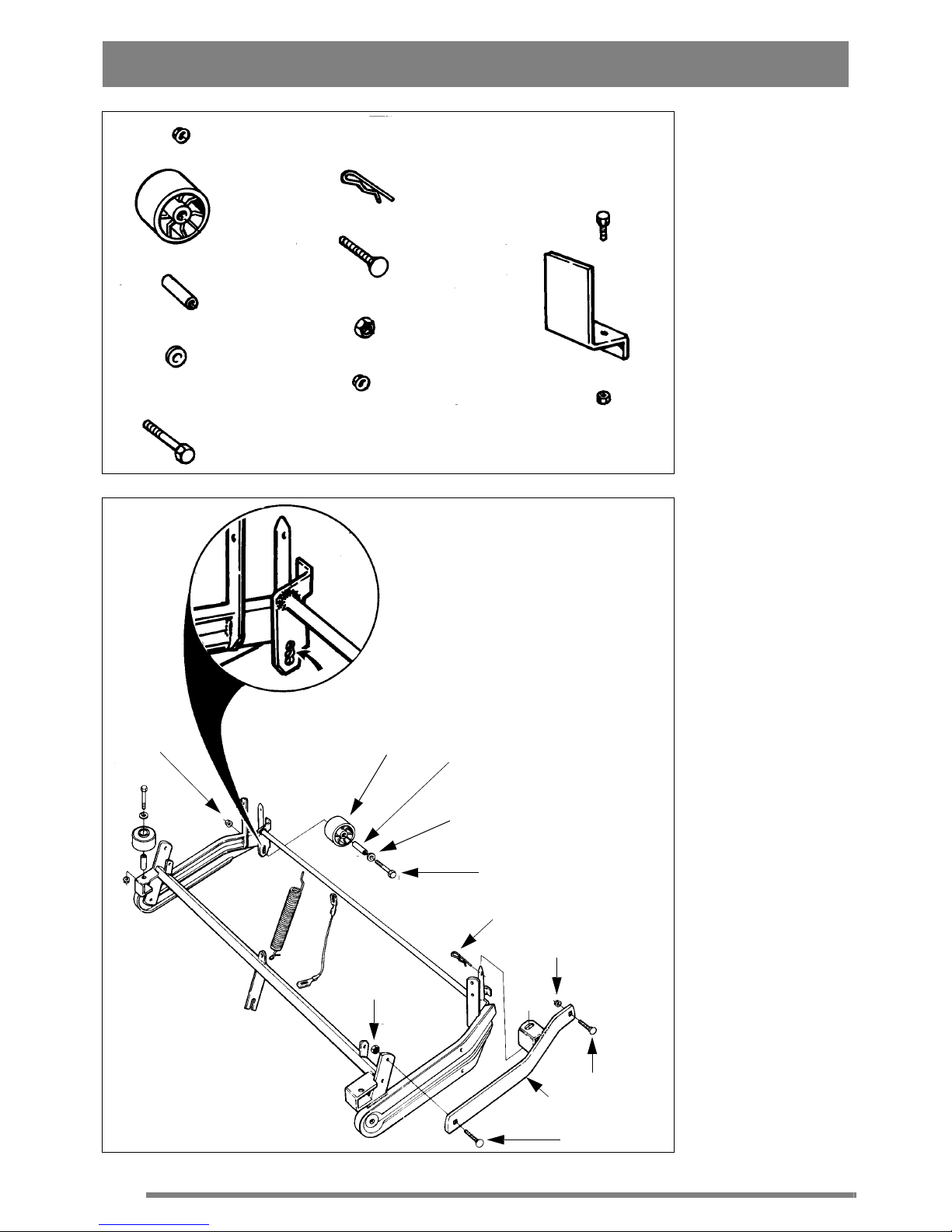
O (x4)
M (x4)
N (x4)
P (x4)
Q (x4)
J (x2)
S (x4)
U (x2)
T (x2)
X (x2)
V (x2)
Y (x2)
O
M
N
P
Q
J
T
U
S
R
S
1.
2.
Page 3
B
C
D
C
F
G
3.
4.
5.
6.
7.
8.
9.
10.
Page 4

Z
X
Y
V
W
11.
15.
16.
12.
13.
17.
14.
18.
Page 5

ENGLISH
GB
SYMBOLS
The following symbols are displayed on the machine in order to remind you about the safety precautions and attention necessary when using the
machine.
The symbols mean:
Warning!
Read the instr uction book and safety manual before using the machine.
Warning!
Do not put hands or feet under the mower
deck casing when the machine is running.
Warning!
Bewareof objects being flung out. Keep
spectators away.
Warning!
Beforestartingany repairwork,removethe
spark plug cable from the spark plug.
ASSEMBL Y - BASE MACHINE
Supplied with the mower deck is a plastic bag containing assembly components (see fig 1 and 3):
Install the mower deck brackets on the base machine:
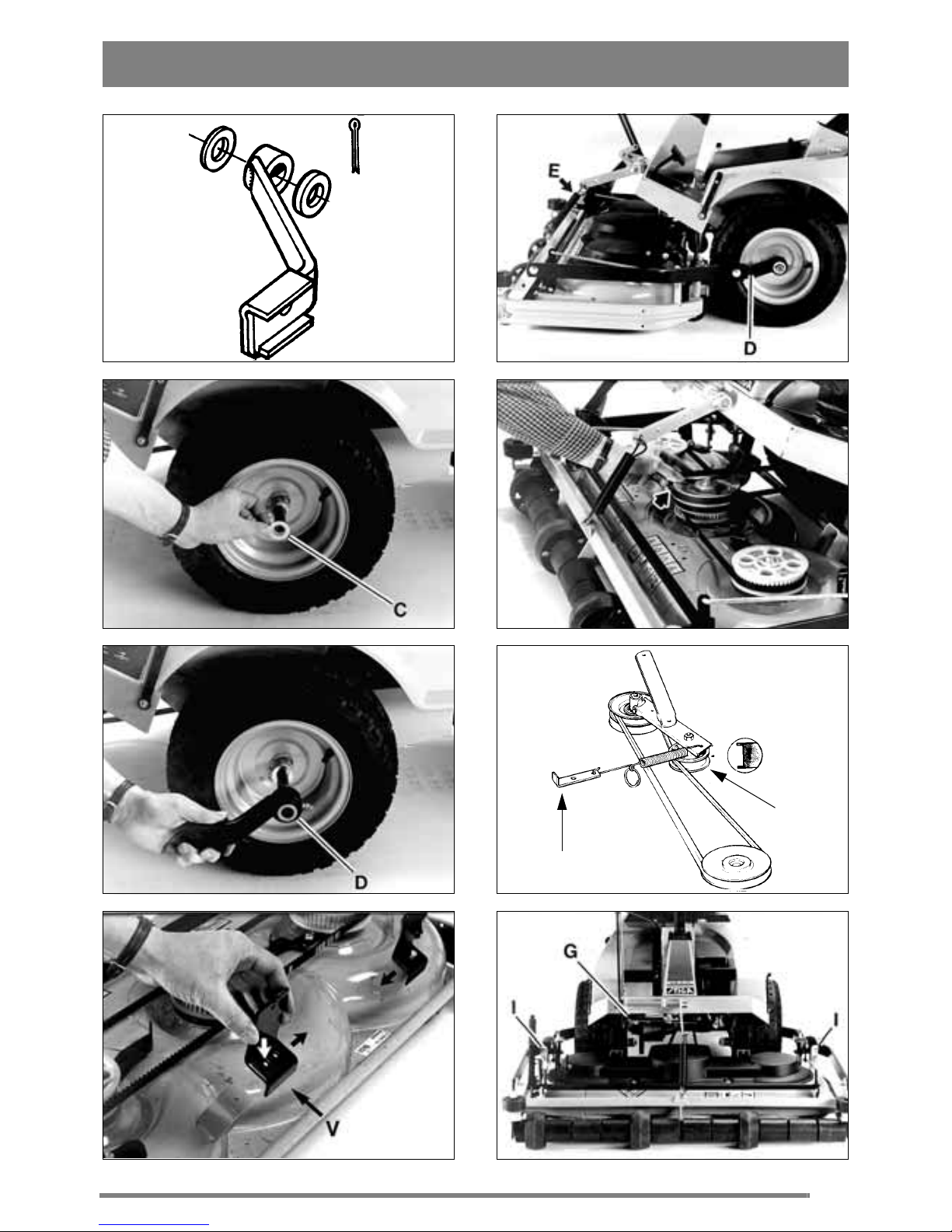
1. Place a washer C on the front wheel stub axle
(fig 4).
2. Then fit a mower deck bracket D (fig 5).
3. Place a second washer C on the outside of the
bracket.
4. Secure in position with a split pin B.
Repeat on the other side of the machine.
The mowerdeck bracketsboth have grease nipples
(see fig 5).
Lubricate these after every 25 hours' service (or at
least once a season) using universal grease.
ASSEMBL Y - MOWER DECK
MOWERDECKSTOPS
Bolt both mower deck stops V onto the deck using
the bolts X and nuts Y (fig 6).
SUPPORT ROLLERS
Fit the four supportrollers M onto the mower deck
frame (fig 2).
The rear supportrollers should normally be placed
in the centre hole.
SUPPORT ARMS
1. Boltthe support armsR securelyonto themower
deckframe by meansof the boltsS and lock nuts U
(fig 2). Do not tighten too hard. It shouldbepossible
to move the support arms up and down.
2. Secure the support arms at the rear by means of
the pins J.
3. Fit the mower deck into the machine's mower
deck bracketsD with the help of the screws S and
the nuts T (fig 7).
4. Hook the mower deck's lifting spring E into the
attachment lift (fig 7).
V-BELT
1. Set the height adjusting lever to position "5".
2. Remove the trans missioncover.
3. Fit the v-belt over the mower deck pulley (fig 8).
4. Check that the tension roller F is resting on the
outside of the v-belt (fig 9).
5. Hook the end of the spring onto bracket G
(fig 9 - 10).
SETTING
For the attachment to mow evenly and cleanly it
needs to be adjusted correctly:
1. Make sure the tyre pressure is correct:
Front:0,4 bar (6 psi).
Rear: 1,2 bar (18 psi).
2. Place the machine on a flat surface. Loosen the
screws I (fig 10).
3.Adjustthe mowerdeck sothat therearend of
the casing is 10 mm higher than the front on
both sides.
Page 6

ENGLISH
GB
4. Tighten the screws.
USE
MOWING HEIGHT
The mower deck has 17 fixed mowing heights,
from 30 mm to 80 mm.
N.B. The stated mowing heights apply when the
machine is standing on firm ground.
Before driving up onto a ramp, trailer
or the like, first adjust the mowing
height to the lowest position.
Otherwise there is a risk that the mower deck will
bedamaged when themower deck stops strikesthe
underside of the base machine.
MOWING HINTS
For the best "Multiclip" effect follow this advice:
- mow regularly.
- use full throttle on the engine.
- keep the underside of the mower deck clean.
- use sharp blades.
- do not mow wet grass.
- mow twice (using different mowing heights)
if the grass is long.
SERVICE AND MAINTENANCE
PREPARATIONS
Unless otherwise stated, all service and maintenance must be performed on a machine that is
standing still where the engine has been switched
off.
Preventthe machinefrom rolling,by always applying the parking brake.
Prevent involuntary engine start by always stopping the engine,looseningthe
spark plug cable from the sparking
plugand earthing it. Remove them inus
(-) cable from the battery.
MAINTENANCE TIPS
The mower deck can easily be raised to facilitate
cleaning and maintenance:
1. Set the height adjusting lever to position "5".
2. Unhook the mower deck lifting spring E from
the attachment lift.
3. Remove the transmission cover.
4. Prise off the v-belt from the mower deck pulley.
5. Remove the two pins J (fig 11).
6. Grasp hold of the mower deck frame (fig 12).
7. Fold up the mower deck until it is standing upright on the two rear support brackets (fig 13).
When refitting for use: Make sure the tension roller F rests on the outside of the v-belt (fig 9).
CLEANING
After use the underside of the mower deck should
be hosed down.
If grass cuttings have dried on to the mower deck,
scrape the underside clean.
If necessary touch-up the underside using a suitable paint to prevent corrosion.
Do not spray with high pressure water
against the bearing housings on top of
the mower deck when the transmission
cover is removed (fig 14). Otherwise
water may penetrate the bearings.
DRIVE BELTS
If any of the blades have hit a solid object (e.g. a
stone) thebelt tension can change. This means that
the drive belt can, "miss-mesh" which in the long
term can damage the blades.
If necessary adjust the drive belt:
1. Dismantle the transmission casing.
2. Loosen the tension arm K (fig 15).
3. Loosen the bearing box's fixing bolts L (fig 16).
4. Tension the drive belt by pressing the tension
arm backwards.
5. Tighten the tension arm's fixing bolts.
6. Tighten the bearing box's fixing bolts.
7. Carry out the same procedure for the other drive
belt.
When changing the drive belts, make
sure that the outer blades are always at
90° to the centre blade (see fig 17).
If you fit the drive belts incorrectly the blades will
collide as they overlap each other.
Page 7

ENGLISH
GB
Always check the position of the blades after
changing the drive belt or adjusting the tension.
CHANGING BLADES
Use protective gloves to prevent cuts
when changing blades/blade tips.
Make sure the blades are always sharp. This gives
the best mowing results.
Always check the blades after an impact. If the
bladesystem has been damaged thedefective parts
must be changed.
Always use original spare parts. Using
non-original spare parts can result in
the risk of damage even if they fit in the
machine.
The cutting system consists of three blade bars,
each with two interchangeable blade tips Y (fig
18). Both blade tips should be replaced at thesame
time to avoid any imbalance.
Fit the new blade tips.Tighten the screws Vand W
fully. Tightening torque: V - 9.8 Nm, W - 24 Nm.
And heavy impact can result in the blade tip being
folded aside. Loosen the locking nut Xand turn the
blade tip back to its correct position. Mount a new
shear bolt V. Tighten the lock nuts X and Z.
SPARE PARTS
STIGA original spare parts and accessories are
constructed exclusively for STIGA machines.
Note that non original spare parts and accessories
have not been checked or approved by STIGA.
Usage of such parts and accessories can
influence the machines operability and
safety. STIGA cannot be held responsible for injuries caused by these products.
STIGA reserves the right to modify the product without
prior notice.
 Loading...