

Stiga STS 520, T8525 Owner's Manual

TABLE TENNIS TABLE
MODEL NO.
T8525
OWNER'S MANUAL
1. Read this manual carefully before starting assembly. Read each step completely before beginning
each step.
2. Some smaller parts may be shipped inside larger parts. Check inside all parts and cartons
before assembling or ordering parts.
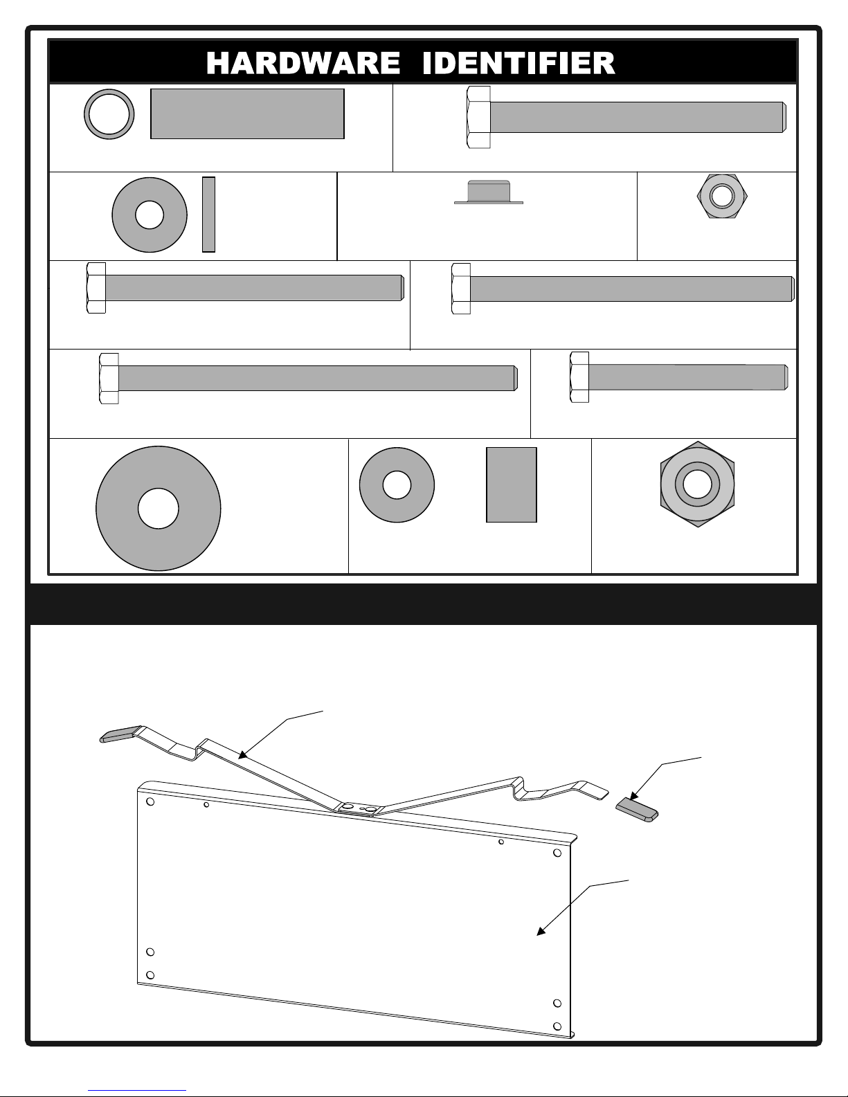
3.To make assembly easier, use the Hardware Identifier on page 2 to identify and sort all
fasteners. Check all cartons for kits. All hardware may not be located in one kit.
4.Do not tighten hardware until instructed to do so. If hardware is tightened too soon, mounting holes
may not align and parts may not easily fit together. Leave locknuts slightly loose until you are instructed to
tighten them.
5. Tools required for assembly: Phillips Screwdriver, Two 9/16” Wrenches, One 7/16” Wrench.
Note: Adjustable wrenches can be substituted for wrenches.
6. Save this instruction manual and your proof of purchase (receipt) in the event that the
manufacturer has to be contacted for replacement parts.
Please Do Not Return This Product To The Store!
Contact Escalade® Sports customer service department at:
Phone:1-866-873-3528Toll – Free !
Fax:1-866-873-3533Toll – Free !
E-mail:tabletennis@escaladesports.com
Mailing Address (correspondence only):
Escalade Sports
PO Box 889
Evansville, IN 47706
Please visit our World Wide Web site at: www.escaladesports.com
ON-LINE TROUBLE SHOOTINGTECHNICAL ASSISTANCE
ON-LINE PARTS REQUESTSFREQUENTLY ASKED QUESTIONS
®
ADDITIONAL ESCALADE
SPORTS PRODUCT INFORMATION
2L-4140-04
Escalade® Sports products may be manufactured and/or licensed under the following patents.
6120397, 5816957, 5769744, 5119741, 4911085, 4717157, D460140, D420563, 8414431
Additional patents may be pending. One or more of the listed patents and/or pending patents may cover specific product.
2013 Escalade Sports
19
25
20
27
22
23
Spacer Bushing (Qty. 4)
Spacer
(Qty. 8)
1/4-20 X 3 Hex Head Bolt
(Qty. 4)
1/4-20 X 4 Hex Head Bolt
(Qty. 4)
3/8” Washer
(Qty. 4)
17
3/8 Push Nut
(Qty. 4)
29
Nylon Spacer
(Qty. 8)
5/16-18 x 3 Hex Head Bolt
(Qty. 4)
28
1/4-20 Locknut
(Qty. 20)
1/4-20 X 3 1/4 Hex Head Bolt
(Qty. 4)
26
1/4-20 X 2 Hex Head Bolt
(Qty. 8)
33
18
M12 Hex Nut
(Qty. 4)
ATTACHING RUBBER PAD
1.
Attach Lock Lever Cap #21 to Lock Levers on the Name Panel # 8 as
shown.
Lock
Lever
21
8
2
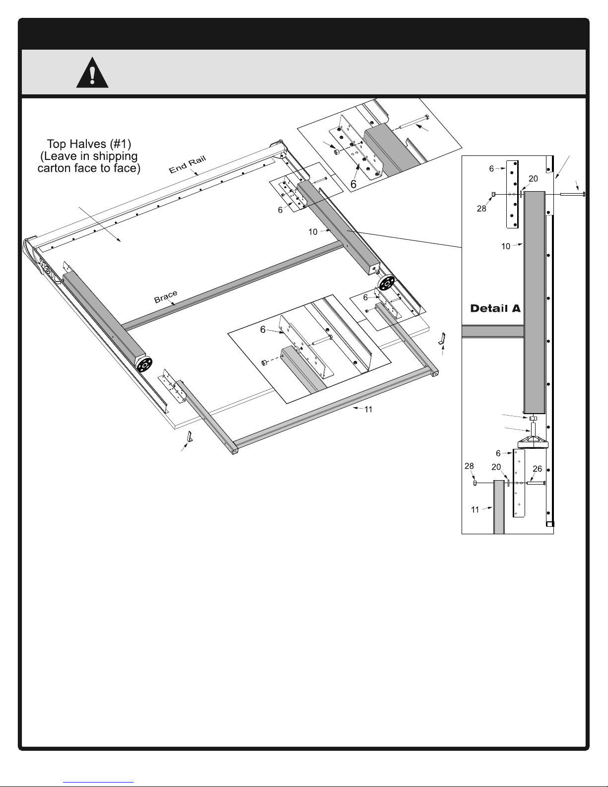
ATTACHING LEGS TO TABLE TOPS
CAUTION
1
AT LEAST TWO ADULTS ARE NEEDED TO
COMPLETE THE FOLLOWING STEPS!
B
etail
D
r M
m
wa
id
o
le
d
y fro
f th
h
e
29
o
m
ta
le
th
e
.
le
b
U
se
osest
cl
Low
er
t
o
t
M
t
he t
e
ddl
i
he bott
abl
28
e
p
Up
Use
st a
e
rth
fu
tto
o
b
e
hol
of
om
e.
Rail not
shown for
clarity.
29
31
2. Leave top halves #1 in shipping carton as shown
above or lay them on a carpeted floor (to protect
them from damage and scratches ).
3. Attach leg assembly #10 to brackets #6 located on
the bottom of the first top half #1. (See above).
Use bolts #29, spacers #20 and locknuts #28.
(See Detail A and Detail B).
NOTE: Be sure brace on leg assembly #10 is against
table (See above). Tighten these locknuts snug but
DO NOT OVERTIGHTEN THEM.
JOINT MUST MOVE!
4. Screw Nuts #33 onto leg levelers # 9 and Put
Levelers #9 on bottom end of leg assembly #10.
(See Detail A)
30
ail C
et
D
33
9
5. Attach upright assembly #11 to remaining brackets
#6 on the bottom of the first top half #1. (See above).
Use bolts #26, spacers #20, and locknuts #28.
(See Detail A and C). Tighten locknuts snug but DO
NOT OVERTIGHTEN them. JOINT MUST MOVE!
6. If not already installed, slide Right # 30 and Left
#31 Rail caps onto the end of the rails as shown.
7. With a helper , set the first top half #1 on its side
against a wall. ( Be sure to put a piece of cardboard,
cloth, or carpeting on the floor first to protect the
top's edges). Turn the second top half #1 over and
repeat steps 3-6 to assemble it.
3
 Loading...