

Stiga T8742, ST4000 Owner's Manual

TABLE TENNIS TABLE
MODEL NO.
T8742 (ST4000)
O W N E R ' S M A N U A L
1. Read this manual carefully before starting assembly. Read each step completely before beginning
each step.
2. Some smaller parts may be shipped inside larger parts. Check inside all parts and cartons
before assembling or ordering parts.
3. To make assembly easier, use the Hardware Identifier on page 2 to identify and sort all
fasteners. Check all cartons for kits. All hardware may not be located in one kit.
4. Do not tighten hardware until instructed to do so. If hardware is tightened too soon, mounting holes
may not align and parts may not easily fit together. Leave locknuts slightly loose until you are instructed to
tighten them.
5. Tools required for assembly: Phillips Screwdriver, Two 9/16” Wrenches, Two 7/16” Wrenches.
Note: Adjustable wrenches can be substituted for wrenches.
6. Save this instruction manual and your proof of purchase (receipt) in the event that the
manufacturer has to be contacted for replacement parts.
Please Do Not Return This Product To The Store!
Contact Escalade® Sports customer service department at:
Phone: 1-800-467-1245 Toll – Free !
Fax: 1-866-873-3533 Toll – Free !
E-mail: tabletennis@escaladesports.com
Mailing Address (correspondence only):
Escalade Sports
PO Box 889
Evansville, IN 47706
Please visit our World Wide Web site at: www.escaladesports.com
ON-LINE TROUBLE SHOOTING TECHNICAL ASSISTANCE
ON-LINE PARTS REQUESTS FREQUENTLY ASKED QUESTIONS
®
ADDITIONAL ESCALADE
SPORTS PRODUCT INFORMATION
2L-5048-00
Escalade® Sports products may be manufactured and/or licensed under the following patents.
6120397, 5816957, 5769744, 5119741, 4911085, 4717157, D460140, D420563
Additional patents may be pending. One or more of the listed patents and/or pending patents may cover specific product.
ÓÓ
2011 Escalade Sports
ÒÒ
SPORTS PRODUCT INFORMATION
2L-5048-00
ÓÓ
ÒÒ
TABLE TENNIS TABLE
MODEL NO.
T8742 (ST4000)
2011 Escalade Sports
2
28
29
30
31
33
34
35
36
37
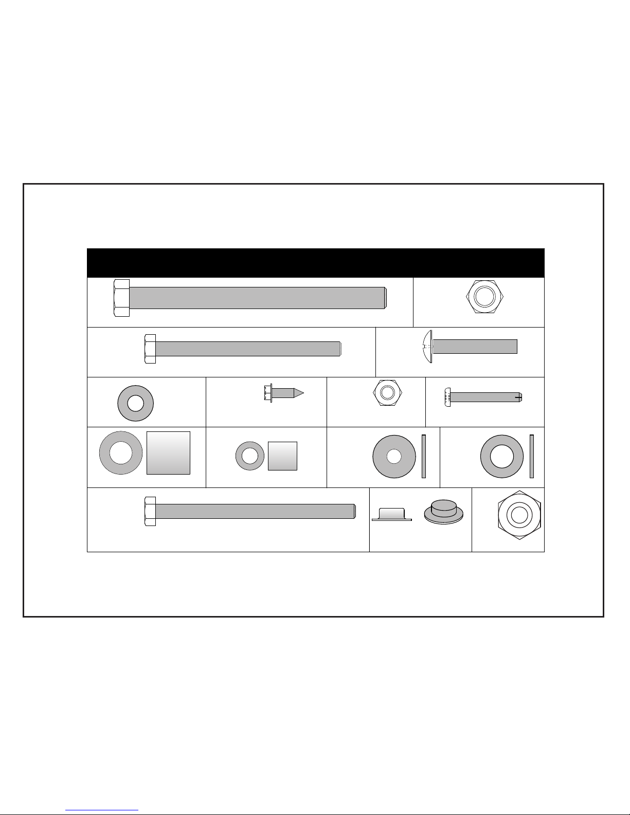
3/8-16 Nyloc Locknut
1/4-20 X 3 1/4 Hex Head Bolt
#8 X 9/16
Sheet Metal Screw
#8-32 X 1 1/4
Sheet Metal Screw
1/2" Long Spacer
3/4" Long Spacer
11
39
1/4"
Plastic
Washer
Washer
Plastic
3/8"
1/4" Nyloc
Locknut
1/4-20 x 1 1/2
Philips Truss Head Screw
1/4"
Flat
Washer
32
1/4-20 X 3 1/2 Hex Head Bolt
3/8" Push Nut
HARDWARE IDENTIFIER
27
3/8-16 x 4 1/2 Hex Head Bolt
38
46
M12 Hex Nut
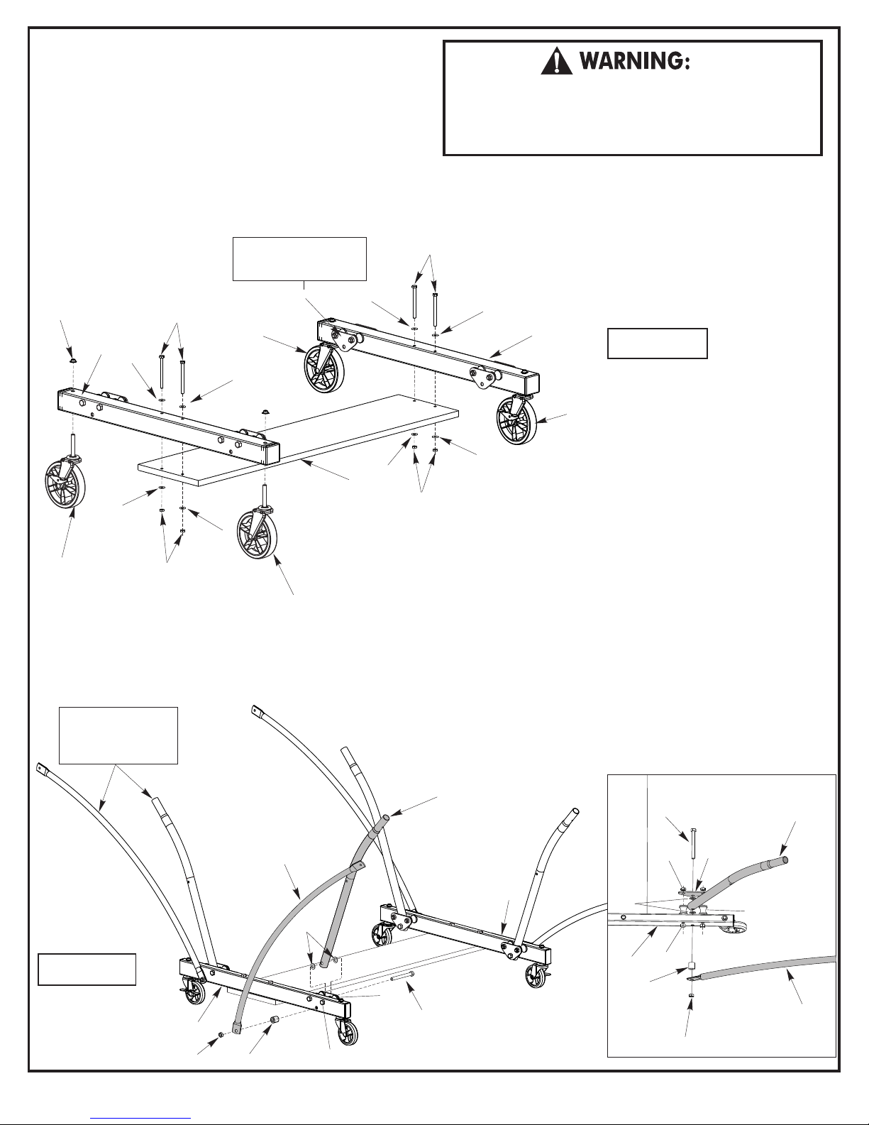
1. Attach Caster Wheels (#9 & #10) to Caster Beam Assembly.
Slide a Caster Wheel with Lock (#10) through Caster Beam
Assembly (#7) and secure it with a Push Nut (#11) as shown
in figure 1. Gently tap the Push Nut (#11) with a hammer
to secure it in place. On the other end of the Caster Beam
attach a Caster Wheel without Lock (#9). Make sure you
have one caster wheel with lock and a caster wheel without
lock for each Caster Beam Assembly.
Repeat this step to attach the Casters to the second Caster
Beam Assembly.
Note: Support Plate (#43)
must be on inside of Caster
Beam (#7) as shown.
11
43
29
7
31
31
Caster
without
Lock
31
31
9
31
31
15
34
3. Attach Strut Tubes (#17) and Linkages (#16) to Caster Beam Assemblies
(#7) as shown in figure 2.
10
Caster
with
Lock
34
9
Caster
without
Lock
a) Loosen Bolts (#13) and Nuts (#28) so that Strut Tube (#17) can fit
between Inner Support Plate (#43) and Caster Beam (#7) as shown in the
Top View and figure 2.
b) Slide one Hex Bolt (#27) through inner Support Plate (#43), followed
by one Plastic Washer (#39), Strut Tube (#17), one Plastic Washer (#39),
pass through Caster Beam (#7), one Spacer (#36), one Linkage (#16),
and Lock Nut (#28).
c) Repeat on other end of Caster Beam (#7) and on second Caster Beam.
Note: Linkages & Strut
tubes must be turned as
shown or table will not
operate correctly.
d) Tighten Bolts (#13) and Nuts (#28) securely.
e) Tighten Nuts (#28) on Bolts (#27) securely.
NOTE: Tighten nuts so that end of Bolt (#27) in even with the edge of nut.
READ AND FOLLOW ALL ASSEMBLY, OPERATING, AND
SAFETY INSTRUCTIONS CAREFULLY. AT LEAST TWO (2)
ADULTS ARE NEEDED TO PUT THIS TABLE TOGETHER!
2. Attach Wood Bottom Board (#15) to Caster Beam
Assemblies (#7) as shown in figure 1. Turn Caster
Beams as shown and attach board with four Hex
Head Bolts (#29), eight Flat Washers (#31) and
29
four Locknuts (#34) Tighten nuts securely.
31
7
Figure 1
Caster
with
10
Lock
31
16
Figure 2
7
28
36
39
13
43
27
27
28
13
28
Top View
(Inner Plate)
43
12
17
16
17
7
39
7
36
3
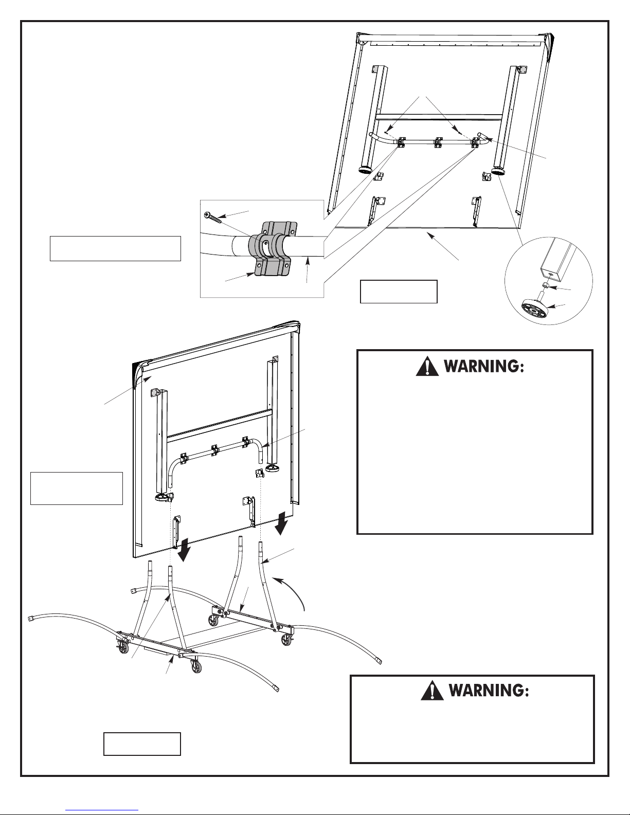
4. Rotate U-support (#21) that is on bottom of Table
Top Assembly until you see the screw holes in the
slots of U-clips (#22). Slide U-support (#21) side
to side if necessary to see holes. See figure 3.
5. Insert Screw (#35) through slot in U-clip (#22)
and into U-support (#21). See figure 3. Thread
screw all the way into U-support until it touches the
back of the tube. There should be about 3/8” of
screw (#35) left sticking out. Repeat for other
screw as shown in figure 3.
6. Attach nut (#46) to leveler (#26) and screw all the
way into leg as shown in Detail 1.
7. Repeat steps 3 and 6 on other
35
table top assembly.
Note: Slide U-Support back and forth
until you see the hole if necessary.
22
21
Figure 3
35
21
U-Support
Table Top
Assembly
46
26
Detail 1
Table Top
Assembly
With at least 2 adults,
slide Table Top Assembly
onto Strut Tubes
Strut Tube
17
AT LEAST TWO (2) ADULTS ARE NEEDED TO
COMPLETE THE REST OF THIS ASSEMBLY! WHEN
21
U-Support
17
Strut Tube
ASSEMBLING TOPS TO BASE, HANDLE TOP
ASSEMBLIES BY GRASPING ONLY THE TOPS
THEMSELVES. DO NOT GRASP METAL LEGS, USUPPORT, LINKAGE, OR HINGES. THESE PARTS
CAN MOVE AND COULD PINCH FINGERS OR
HANDS CAUSING SERIOUS INJURY! ASSEMBLE
AS SHOWN WITH LEGS FULLY CLOSED AND
TOPS IN A VERTICAL POSITION. DO NOT OPEN
LEGS AND TRY TO ASSEMBLE. TABLE TOPS ARE
HEAVY - DO NO T ATTEMPT TO ASSEMBLE
ALONE!
8. Attach Table Top Assembly to Base Assembly (that
PIVOT STRUT
7
TUBES UP
you put together in steps 1 & 2), as shown in
figure 4. Pivot Strut Tubes (#17) up as shown;
then, with at least one adult on each side of Table
Top, lift top and align ends of U-support tube (#21)
with tops of Strut Tubes (#17) on Caster Beams
(#7) as shown in figure 4. Slide tubes together.
7
Figure 4
DO NOT OPEN THE TABLE TO PLAYING POSITION
UNTIL BOTH TOPS ARE INSTALLED! DO NOT LEAVE
TABLE STANDING UNATTENDED. IT COULD BE
KNOCKED OVER CAUSING SERIOUS BODILY INJURY
OR PROPERTY DAMAGE.
4
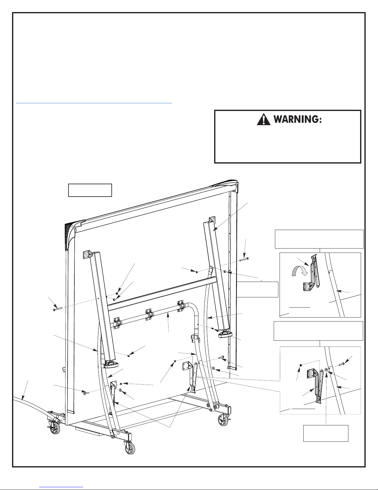
9. Screw U-support tube (#21) to Strut Tubes (#17) with two Screws
(#33) as shown in figure 5. Align holes in U-support with holes in
Strut Tubes and thread screw (#33) into hole in Strut Tube (#17)
tighten screws all the way but be careful not to over tighten. You
could strip threads on screws if you over tighten.
Note:
Due to shipping requirements the hinge (#18) may be positioned as
shown in Detail A, you will have to rotate the hinge to the position shown
in Detail B. DO NOT unscrew the hinge, you can rotate the hinge
without unscrewing it from the table.
If you want to see a video on how to position hinge (#18) go to:
http://www.escaladesports.com/customer-service/videos.html
10. Attach Hinges (#18) to Strut Tubes (#17) as shown in figure 5,
Detail B. With hinge positioned as shown, align hole in hinge with
hole in Strut Tube and attach with ¼” Screw (#30), Plastic Washer
(#38) and Locknut (#34). Plastic Washer (#38) goes between Strut
Tube and Hinge. Tighten nut securely. Repeat for other Hinge.
CAUTION: Hinges must be positioned exactly as shown or
table will not operate correctly and could be damaged.
DO NOT take hinges off.
Figure 5
11. Attach Linkages (#16) to Leg (#19) as shown in
figure 5. Pivot one Linkage (#16) up and pivot
Leg out from top and align hole in Linkage with
hole in Leg (#19). Attach Linkage (#16) to Leg
(#19) using Hex Head Bolt (#32), Spacer (#37)
and Locknut (#34). Spacer (#37) goes between
Linkage and Leg. Attach other Linkage to Leg the
same way. Tighten nuts securely.
12. With at least two adults, repeat steps 6
through 9 for other table top assembly..
DO NOT OPEN THE TABLE TO PLAYING POSITION
UNTIL BOTH TOPS ARE INSTALLED! DO NOT LEAVE
TABLE STANDING UNATTENDED. IT COULD BE
KNOCKED OVER CAUSING SERIOUS BODILY INJURY
OR PROPERTY DAMAGE.
19
16
32
16
30
17
34
37
38
33
34
21
17
34
32
Spacer goes between
Linkage Arm (#16)
and Leg (#19)
5
16
33
30
38
ATTENTION: If hinge is positioned as
shown below (Detail A), Rotate the hinge as
shown in Detail B. Do not take hinge off.
18
37
Shipping position
of hinge
CAUTION: Position Hinges exactly as
shown in Detail B or table will not operate
correctly and could be damaged.
Detail B
34
18
Assembly
position of hinge
Detail A
17
30
38
17
18
Hinge Assembly
Plastic Washer goes
between Strut Tube
(#17) and Hinge (#18)
5

 Loading...