

Page 1
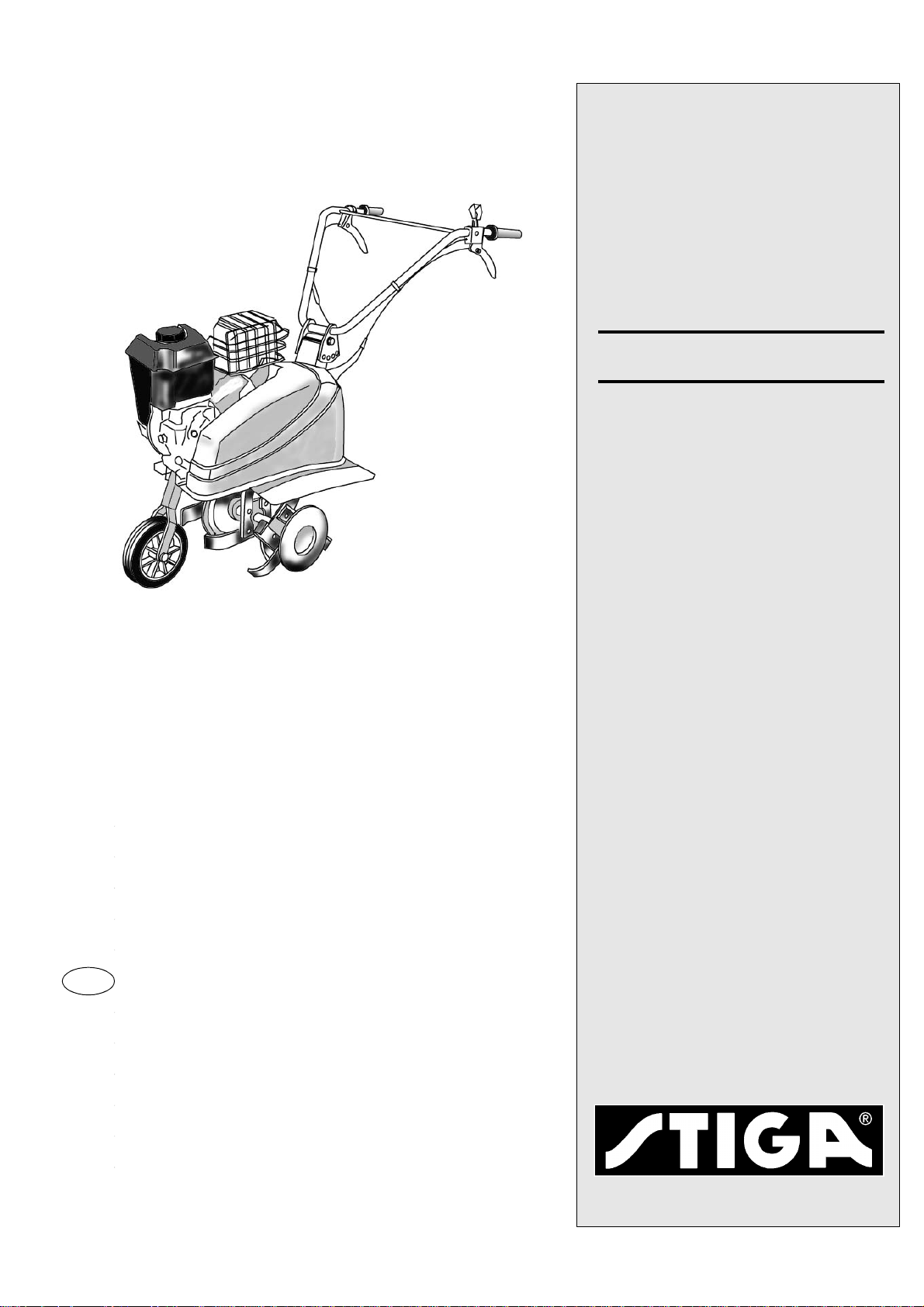
JB 55
EN OPERATOR´S MANUAL
PL
CS
8214-2227-01
,16758.&-½2%6¥8*,
192'
Page 2

Page 3

EN
ENGLISH
1 SYMBOLS, SEE FIG. 1
The following symbols can be found on the tiller. Their purpose it to remind you of the care and attention required when
using it. If any symbol is mis sing, damaged or u nreadable, i t
should be immediately replaced with a new one. The symbols mean:
1. Warning! Read the instructions.
2. Warning for rotating blades.
3. Reverse gear.
4. Clutch handle. Handle out, left fig. = disengaged. Handle
pressed in, right fig. = engaged.
5. Throttle control, a=fast, b=slow and c=stop.
6. Read the instructions and remove the spark plug lead before doing any work. Wear protective gloves.
2 SAFETY INSTRUCTIONS
2.1 GENERAL
• Read through this instruction book carefully and make
sure you understand the contents before using the tiller.
• The tiller must only be used for gardening purpos es.
• Keep children away from the tiller.
• Do not allow children or persons who have not read the
instructions to handle the tiller.
• The tiller is manufactured in accordance with current
standards, and must not be modified or rebuilt.
• All the symbols on the tiller should be kept intact.
• The user is liable for damages incurred by a third party.
WARNING for petrol. Petrol is highly inflammable: Petrol must be stored in the requisite contai-
ners.
• Always fill-up outdoors and with the engine switched off.
• Do not smoke when filling-up.
• There must be no n aked flames or oth er sources of heat in
the vicinity of the petrol.
• Do not start the engine if petrol has spilled out. Move the
machine and allow the petrol to evaporate before starting
the machine.
• Screw on the filler cap correctly after filling up.
• Set the throttle control in the "Stop" position, and close
the petrol cock when the machine has been stopped.
• Switch off the engine before transporting the machine.
Never lift the machine by yourself. The machine is lifted
by two persons, one on each side holding the steering and
the rotor axle. W ear protective gloves and hold the machine upright whe n lifting.
• When the machine is loaded on a trailer or tailboard it
should be run up on a ramp by using its wheel.
2.2 PREPARATIONS
• Before starting work, remove all foreign objects such as
stones, glass, cables, metal objects and other loose objects.
• Toys, hoses and other objects can be damaged.
• Check that the tiller is in good condition before using it.
• Check that all nuts and bolts are tightened.
2.3 OPERATING
• Always operate the machine at low speed when working
on stony ground.
• Do not change the engine's speed setting. Th e engine
must not be overspeeded.
• The work area should be well illuminated during the
work.
• The tiller must not be used when ot her persons, especially
children, are in the vicinity.
• The tiller must not be used without the splashguards or
protective cover.
• The tiller must not be used if the operator is ill, has taken
medicine, or is under the influence of other substances
which reduce one's reactions.
• The tiller must not be used on terrain which slopes more
than 20°.
• The user is responsible to ensure that all risks in the terrain are taken into consideration, and th at procedu res are
taken to prevent accidents. This particularly applies to
sloping, slippery or loose terrain.
• Start the engine carefully, according to the instructions in
this manual. No parts of the body must come in contact
with the rotors.
• The engine must never be started in an enclosed area.
• The carbon monoxide in the engine's exhaust fumes is
poisonous and can cause death.
• Wear tightly fitting clothes and heavy-duty shoes which
completely cover the feet.
• The tank should only be half full when operating on slopes. Petrol can leak out.
• The engine must be stopped in the following circumstances:
• When the machine is left unattended
• Before the machine is filled up with petrol
• Always make sure y ou have a g ood footing, especially on
slopes.
• Check that no one is in front of you or beside you when
starting the blades. Keep a steady grip on the steering.
The machine will lift when the rotors are started. Use extra caution when backing.
Page 4

ENGLISH
• Always keep at a safe distance to the rotors when working.
• Holding the steering correctly ensures a safe distance.
• No person must come closer than 20 m to the machine
when working on slopes. The user must hold the steerin g
firmly with both hands all the time.
• W orking on stony or hard ground demands extra attent ion
from the operator. The machine becomes more unstable.
• Never touch the engine when operating the machine, or
just afterwards. Risk for burn injuries.
2.4 AFTER OPERATING
• Allow the engine to cool before putting th e mach ine in a
storeroom. Fire risk!
• Remove dirt and foreign material before putting the machine in a storeroom. The area round the petrol tank and
muffler must be kept clean from leaves, oil, petrol or
other foreign materials. Fire risk!
• If the petrol tank is to be emptied, do this outdoors and
when the engine is cold. Fire risk!
• The machine should be stored in a dry place. The machine must not stored with fuel in the tank in rooms where
there are naked flames, sp arks or ot her st ro ng s ou rces of
heat.
2.5 MAINTENANCE
• Carry out maintenance regularly. All nuts and bolts
should always be tight.
• Only use genuine spare parts wh ich are in good condition. Spare parts must not be rep aired. They must be replaced if they are defective. Poor quality spare parts can lead
to personal injury. If the muffler is damaged it must be replaced.
• The engine must be stopped an d the spark plug lead disconnected in the following circumstances:
When adjusting the rotors.
When the machine is to be cleaned or repaired. When
checking after a collision with a solid hard object. Carry
out the necessary repairs before continuing to work.
If the machine begins to vibrate abnormally. Carry out
the necessary repairs before continuing to work.
• Wear protective gloves when working with the rotors.
3 DELIVERY
The tiller is delivered in a box with the steering and side plates dismantled. All the wires are fitted and adjusted.
WARNING! There is no oil in the engine on
delivery.
EN
4 DESCRIPTION, SEE FIG. 2
The tiller is driven by a four-stroke engine and consists of the
following parts:
1. Clutch control, activation of the blades
2. Gear control, forward/reverse
3. Steering adjuster
4. Air filter
5. Manual start
6. Splashguard
7. Tail brake
8. Data plate
9. Side roller
10. Throttle control
11. Fuel tank
12. Oil filler
13. Oil plug
14. Support wheel
15. Rotors, 4, the outer rotors can be removed. The working
width then becomes 340 mm
16. Cover
17. Cover f o r muffler
18. Exhaust
19. Handle
The data plate (8) contains the following information.
See fig. 3.
A Nominal power
B Weight in kg
C Serial number
D Year of manufacture
E Type F Manufacturer
G CE-mark
H Max. engine speed
5 ASSEMBLY
5.1 STEERING, SEE FIG. 4
Fit the steering (1) according to the figure with the bolt (2),
washer (3), nut (4), bolt (5), washer (6) and nut (7). Choose
a suitable hole for the bolt (5) for comfortable adjustment of
the steering (1).
5.2 SPLASHGUARD, SEE FIG. 2
Fit the splashguards (6) on both sides with the en clos ed nuts
and bolts.
Page 5

EN
ENGLISH
5.3 SUPPORT WHEEL, SEE FIG. 5
Fit the support wheel according to the figure. Do not tighten
the nut (5) too hard. It will not be possible to fold the wheel
arm up.
5.4 FILLING THE OIL, SEE FIG. 2
Remove the plug (12) and fill up with 0.7 L of oil, SAE
10W40. Screw the plug back on.
5.5 ROTORS AND SIDE ROLLERS, SEE FIG. 6
The first rotor (1) is pushed on the axle shaft (2) and locked
with the cotter (3). After which the second rotor (4) is inserted in the first and locked with the cotter (3). Max. 3 rotors
can be fitted in this way on each side. Finally, fit the side rollers in the same way.
WARNING! Check that the cotters are locked,
i.e. that the springs are locked round the shaft.
6 OPERATING
See also section 2.3.
WARNING! Check the engine's oil level. See section 8.4.
6.1 FILLING THE FUEL, SEE FIG. 7
See the safety instructions in section 2.1. Fill up with 2.8 L
of unleaded petrol, and screw on the filler cap.
NOTE! Remember that standard unleaded petrol is perishable. Do not buy more petrol than what can be consumed in 30
days. Environmentally adapt ed petr ol (acr ylic petrol) can be
used to advantage. This petrol is more environmentally-friendly.
6.2 ST ART
See the safety instructions in section 2.3. A cold engine is
started as follows:
1. Open the petrol cock. See fig. 8.
2. Set the choke lever in the choke position. See fig. 11b.
3. Set the throttle control to idle. See fig. 10.
4. Pull the starter handle, first gently until the pawls grip,
and then with a strong tug until the engine starts. See (5)
in fig 2.
NOTE! Do not let go of the cord when the engine has
started, but follow it back slowly with your hand!
5. Set the throttle control in mid position.
6. Set the choke in position "Ru n". See fig 9. A warm engine
is started in the same way as above, but without steps 2
and 6.
6.3 FORWARD OPERATION, SEE FIG. 2.
Forward gear is selected when the left handle, the gear control (2), is not pushed in. The tiller starts forward when the
clutch handle (1) is pulled in. Go forwards as follows:
1. Set the throttle control (10) in the required position.
2. Pull in the clutch handle (1). The tiller stops moving forward when the clutch handle (1) is released.
6.4 BACKWARD OPERATION, SEE FIG. 2
WARNING! The gear control (2) must only be pulled in when the clutch handle (1) is not pulled in.
Go backwards as follows:
1. Set the throttle control (10) in the required position.
2. Pull in the gear control (2).
3. Pull in the clutch handle (1). The tiller stops moving
backwards when both handles are released.
6.5 STOPPING, SEE FIG. 11
Stop the tiller as follows: 1 Set the throttle control in stop position. See fig. 11a 2 Set the choke lever in choke position.
See fig. 11b. 3 Close the petrol cock. See fig. 11c.
6.6 OPERATING TIPS
The rotors drive the machine fo rward. The speed of the rotors
is regulated with the throttle control.
WARNING! Keep hands and feet away from the
rotors.
Adjust the number of rotors on each side to the required working width. See section 5.5.
When the machine is braked with the help of the tail brake,
the rotors dig down into the earth. The working depth depends upon how much the tail brake is forced down into the
ground while working. The correct working depth determ ines how easily the work is done. The optim al working depth
varies with the ground conditions. Try it and see.
Never use the machine in wet soil. Lumps form, which are
then difficult to crush. Hard and dry soil necessitates making
a second run, at right angles to the first.
WARNING! Never overload a new machine. Run
the machine carefully the first 5 hours.
7 STORAGE
The tiller should be stored in a dry place.
See also section
2.4.
After the petrol has been drain ed off, start the engine and allow it to run until all the remaining petrol is used up.
Page 6

ENGLISH
8 MAINTENANCE
WARNING! Repairs must be carried out by the
dealer. Otherwise the warranty is not valid.
WARNING! The spark plug lead should be disconnected before carrying out repairs or maintenance.
8.1 PERIODIC MAINTENANCE
8.1.1 Before using the machine
• Check the oil level in the engine. Top up if necessary.
• Check that there is no oil leakage.
• Check that all the bolts are tightened.
8.1.2 After using the machine
• Clean the tiller.
• Check that there is no oil leakage.
8.1.3 Every 20 working hours
• Check, and clean or replace the air filter.
• Check that all nuts and bolts are tightened.
8.1.3 Change the oil in the engine every year.
8.2 TO DRAIN OFF THE PETROL
see section 2.4.
8.3 AIR FILTER, SEE FIG. 12
Clean/change the air filter regularly. Unscrew the screw (A)
to remove the air filter.
WARNING! Never use inflammable liquids when
cleaning.
Clean the air filter by brushing it clean with a soft brush.
EN
8.5 CLEANING
See section 2.4. First brus h off all the loose dirt. Then wipe
the tiller with a damp cloth. The frame can be flushed clean
with water.
8.6 REPLACEMENT OF DRIVE BELT, SEE FIG 13
1. Remove the cover (16) in fig. 2.
2. Lift the tensioning pulley (2) and work off the belt.
3. Work off the belt from the two pulleys. The clamp (A)
over the small pulley should not be removed.
4. Fit the new belt in the reverse order.
5. Adjust the clutch wire. See below.
6. Fit the cover.
8.7 ADJUSTING THE CLUTCH WIRE
1. Remove the cover (16) in fig. 2.
2. Adjust the clutch wire with the tensioning sleeve (A) in
fig. 14.
3. The clutch wire is correctly adjusted when the spring (B)
in fig. 15 extends approx. 1 cm when the handle is pressed in.
4. Lock the tensioning sleeve and fit the cover after adjusting.
8.8 ADJUSTING THE GEAR WIRE
1. Adjust the gear wire with the tensioning sleeve (C) in
fig. 16.
2. The gear wire is correctly adjusted when the play in the
end of the handle is approx. 5 mm. See fig. 17.
NOTE! Do not tighten the gear wire too hard. This can re-
duce its lifetime.
3. Lock the tensioning sleeve after adjusting.
8.4 CHANGING/CHECKING THE OIL, SEE FIG. 2
The engine oil should be changed every year . Change the oil
as follows:
1. Run the engine warm. W ARN ING! The engine oil is hot.
Risk for burn injuries.
2. Tilt the machine forward and remove the plug (13).
Drain off the oil into a suitable container. Fit the plug
when the oil is drained off.
3. Put the machine horizontal.
4. Remove the plug (12) and fill up with 0.7 L of oil, SAE
10W40. Screw the plug back on.
5. The oil level should be level with the bottom edge of the
hole for the plug (12) when the machine is horizontal.
8.9 TROUBLE SHOOTING
8.9.1 Fault: Difficult to start.
Reason: The fuel is too old.
Procedure: Drain the tank and fill up with new petrol.
Reason: Fault on spark plug.
Procedure: Replace spark plug.
8.9.2 Fault: The engine does not run smoothly.
Reason: Dirt in the fuel.
Procedure: Clean the petrol tank and carburettor.
Reason: Fault on spark plug.
Procedure: Replace spark plug.
8.9.3 Fault: The engine has no power, will not run at full
throttle.
Reason: Blocked air filter.
Procedure: Clean or replace air filter.
Page 7

EN
8.9.4 Fault: Slips when moving forward.
Reason: The belt is too slack.
Procedure: Adjust the belt.
8.9.5 Fault: Slip s when moving bac kward.
Reason: The gear control is incorrectly adjusted.
Procedure: Adjust the gear control.
8.9.6 Fault: Stops under operation.
Reason: Run out of fuel.
Procedure: Fill up with petrol.
ENGLISH
9 TECHNICAL DATA
Weight: 46 kg
Type of engine: 4-stroke, Briggs & Stratton
Spark plug: Champion QC12YC or the equivalent.
Power: 4 kW (5.5 hp)
Engine speed: 3400 rpm
Sound pressure
level: 77 dB(A)
Vibration level: 2.9 m/s
Transmission: Belt gear with gearbox
Fuel tank, capacity: 2.8 litres
Fuel: 95 octane, unleaded petrol
Steering handles: Vertically adjustable.
Blade diameter: 320 mm
Working width: 590 mm (84 0 mm with 6 rotors and
Rotation of blades
forward: 135 rpm
Rotation of blades
backward: 58 rpm
2
340 mm with 2 rotor s )
10 CE CERTIFICATE
Ets PUBERT SA Z.I. de Pierre-Brune, 85110 CHANTONNAY, France warrants that tiller JB 55 complies with the essential health and safety requirements in the directives 89/
392 CEE and 98/37/CE. To guarantee correct application of
the safety and health requirements stipulated in the EEC Directive, the following standards and/or technical specifications have been consulted: EN 292-1, EN 292-2, EN 25349
(1993) and NFU 02-025 .
Chantonnay 01 01 99
M. Jean-Pierre PUBERT
Chairman and CEO
Page 8

Fig. 1
123 4
5a
5b
5c
6
Fig. 2
10
211 6
1
2
3
4
5
11
12
13
12
13
1
3
16
6
10
19
2
6
7
7
8
915
14
15
9
Fig. 3.
Fig. 4.
Page 9

Fig. 5.
Fig. 6.
Fig. 8.
4
2
1
CHOKE
RUN
3
Fig. 9.
Fig. 7.
Fig. 11a.
Fig. 10.
CHOKE
RUN
Fig. 11b. Fig. 11c.
Page 10

A
+1 cm
5 m m
1
Fig. 12.
A
Fig. 13.
Fig. 15.
C
Fig. 16.
Fig. 14.
A
Fig. 17.
Page 11

 Loading...