


STIEBEL ELTRON WWS 20 Operation And Installation
BEDIENUNG UND INSTALLATION
OPERATION AND INSTALLATION
UTILISATION ET INSTALLATION
Warmwasser-Wärmepumpe in Splitbauweise | DHW heat pump in a split design |
Chauffe-eau thermodynamique de conception split
» WWS 20
1:1

CONTENTS | SPECIAL INFORMATION
CONTENTS
SPECIAL INFORMATION
OPERATION
1. General information ��������������������������������������� 38
1.1 Safety instructions ����������������������������������������������38
1.2 Other symbols in this documentation ���������������������� 38
1.3 Information on the appliance ��������������������������������39
1.4 Units of measurement ����������������������������������������� 39
1.5 Standardised output data ������������������������������������� 39
2. Safety �������������������������������������������������������� 39
2.1 Intended use ����������������������������������������������������� 39
2.2 Incorrect use ����������������������������������������������������� 39
2.3 General safety instructions �����������������������������������39
2.4 Test symbols �����������������������������������������������������40
3. Appliance description ������������������������������������� 40
3.1 Heating the DHW cylinder ������������������������������������ 40
3.2 Appliance operation outside the application limits ������ 41
3.3 Frost protection (air as heat source) ������������������������ 41
3.4 Display and control elements �������������������������������� 41
4. Menu structure ��������������������������������������������� 42
4.1 Switching on heat pump �������������������������������������� 43
4.2 Standard display ������������������������������������������������ 43
4.3 DHW heating ����������������������������������������������������� 43
4.4 Fan mode ���������������������������������������������������������44
4.5 Heat pump mode selection ����������������������������������� 45
4.6 Operation with external signal transmitter ��������������� 45
4.7 Electric heater rod ���������������������������������������������� 46
4.8 Setting the time ������������������������������������������������� 46
4.9 Parameter level �������������������������������������������������46
5. Cleaning, care and maintenance ������������������������� 47
6. Troubleshooting �������������������������������������������� 47
INSTALLATION
7. Safety �������������������������������������������������������� 49
7.1 General safety instructions ����������������������������������� 49
7.2 Instructions, standards and regulations ������������������� 49
8. Appliance description ������������������������������������� 49
8.1 Standard delivery ����������������������������������������������� 49
8.2 Accessories ������������������������������������������������������� 49
8.3 Incorrect use ����������������������������������������������������� 49
9. Preparations ������������������������������������������������ 49
9.1 Transport ��������������������������������������������������������� 49
9.2 Storage ������������������������������������������������������������50
9.3 Installation site �������������������������������������������������� 50
9.4 Heat source (air draw-off point) ����������������������������� 51
10. Installation �������������������������������������������������� 51
10.1 Wall mounting bracket installation ������������������������� 51
10.2 Siting the appliance �������������������������������������������� 52
10.3 Water connection ����������������������������������������������� 52
10.4 Condensate drain ����������������������������������������������� 54
10.5 Power supply ���������������������������������������������������� 54
10.6 Temperature sensor �������������������������������������������� 55
11. Commissioning ��������������������������������������������� 55
11.1 Initial start-up ��������������������������������������������������� 55
11.2 Recommissioning ����������������������������������������������� 56
12. Appliance shutdown ��������������������������������������� 56
13. Maintenance and cleaning �������������������������������� 56
13.1 Removing the casing ������������������������������������������� 56
13.2 Removing casing components separately ����������������� 57
13.3 Cleaning the evaporator ��������������������������������������� 57
13.4 Water treatment�������������������������������������������������57
13.5 Descaling the appliance ��������������������������������������� 57
14. Specification ������������������������������������������������ 58
14.1 Dimensions and connections ��������������������������������� 58
14.2 Hydraulic connection diagram ������������������������������� 59
14.3 Wiring diagrams ������������������������������������������������ 61
14.4 Heating output �������������������������������������������������� 65
14.5 Power consumption �������������������������������������������� 65
GUARANTEE
ENVIRONMENT AND RECYCLING
14.6 Data table �������������������������������������������������������� 66
SPECIAL INFORMATION
- The appliance may be used by children aged8
and up and persons with reduced physical, sensory or mental capabilities or a lack of experience
and know-how, provided that they are supervised
or they have been instructed on how to use the
appliance safely and have understood the resulting risks. Children must never play with the appliance. Children must never clean the appliance
or perform user maintenance unless they are
supervised.
- Observe all applicable national and regional regulations and instructions during installation.
- The appliance is not approved for outdoor
installation.
- Observe the minimum clearances (see chapter "Installation/ Preparations/ Siting the
appliance").
- Observe the requirements concerning the installation room (see chapter "Installation/ Preparations/ Installation site").
ENGLISH
www.stiebel-eltron.com WWS 20 | 37
SPECIAL INFORMATION | OPERATION
General information
- In the case of a permanent connection, the appliance must be able to be separated from the
power supply by an isolator that disconnects all
poles with at least 3mm contact separation. Contactors, mains isolators or fuses can be used for
this.
- Observe the safety measures to prevent contact
with dangerous 'live' currents.
- Observe the MCB/fuse protection required for
the appliance (see chapter "Specification/ Data
table").
- In the event of damage to the power cable this
must always be replaced by a qualified contractor
authorised by the manufacturer, using original
spare parts.
- The appliance is pressurised. During the heat-up
process, expansion water will drip from the safety
valve.
- Install a type-tested safety valve in the cold water
supply line.
- The maximum pressure in the cold water supply
line must be at least 20% below the response
pressure of the safety valve. If the maximum
pressure in the cold water supply line is higher,
install a pressure reducing valve.
- Size the drain so that water can drain off unimpeded when the safety valve is fully opened.
OPERATION
1. General information
The chapters "Special information" and "Operation" are intended
for both users and qualified contractors.
The chapter "Installation" is intended for qualified contractors.
Note
Read these instructions carefully before using the appliance and retain them for future reference.
Pass on the instructions to a new user if required.
1.1 Safety instructions
1.1.1 Structure of safety instructions
KEYWORD Type of risk
!
Here, possible consequences are listed that may result
from failure to observe the safety instructions.
Steps to prevent the risk are listed.
1.1.2 Symbols, type of risk
Symbol Type of risk
!
Injury
Electrocution
Burns
(burns, scalding)
- Fit the discharge pipe of the safety valve with
a constant downward slope and in a room free
from the risk of frost.
- The safety valve discharge aperture must remain
open to atmosphere.
1.1.3 Keywords
KEYWORD Meaning
DANGER Failure to observe this information will result in serious
WARNING Failure to observe this information may result in serious
CAUTION Failure to observe this information may result in non-seri-
injury or death.
injury or death.
ous or minor injury.
1.2 Other symbols in this documentation
Note
General information is identified by the adjacent symbol.
Read these passages carefully.
Symbol Meaning
!
Material losses
(appliance damage, consequential losses and environmental pollution)
Appliance disposal
38 | WWS 20 www.stiebel-eltron.com

OPERATION
Safety
This symbol indicates that you have to do something. The ac-
tion you need to take is described step by step.
1.3 Information on the appliance
Symbol Meaning
Never cover the appliance
1.4 Units of measurement
Note
All measurements are given in mm unless stated otherwise.
1.5 Standardised output data
Explanations to determine and interpret the specified standardised
output data
Standard: EN 16147
The output data specifically mentioned in text, diagrams and
technical datasheets has been calculated according to the test
conditions of the standard shown in the heading of this section.
Generally, these standardised test conditions will not fully meet
the conditions found at the installation site of the system user.
Depending on the chosen test method and the extent to which this
method deviates from the conditions defined in the norm shown in
the heading of this section, any deviations can have a considerable
impact. Additional factors that have an influence on the test values
are the measuring equipment, the system configuration, the age
of the system and the flow rates.
A confirmation of the specified output data can only be obtained
if the conditions applicable to the relevant test match those of the
standard shown in the heading of this chapter.
2. Safety
2.1 Intended use
The appliance is intended for DHW heating within the application
limits detailed in chapter "Specification/ Data table".
The appliance is intended for domestic use. It can be used safely
by untrained persons. The appliance can also be used in non-domestic environments, e.g. in small businesses, as long as it is
used in the same way.
Any other use beyond that described shall be deemed inappropriate. Observation of these instructions and of instructions for any
accessories used is also part of the correct use of this appliance.
2.2 Incorrect use
The following are not permitted:
- Heating liquids other than DHW
- Operating the appliance with an empty DHW cylinder
- Operating the appliance outside the application limits (see
chapter "Specification")
- Interrupting the power supply
2.3 General safety instructions
Only qualified contractors should carry out the electrical work and
installation of this appliance. Qualified contractors are responsible
for adherence to all applicable regulations.
The appliance should only be operated once it is fully installed
and all safety equipment has been fitted.
WARNING Injury
!
The appliance may be used by children aged 8 and up and
persons with reduced physical, sensory or mental capabilities or a lack of experience and know-how, provided
that they are supervised or they have been instructed on
how to use the appliance safely and have understood
the resulting risks. Children must never play with the
appliance. Children must never clean the appliance or
perform user maintenance unless they are supervised.
WARNING Electrocution
Contact with live components presents a threat to life.
Damage to the insulation or to individual components
may result in a threat to life.
If there is damage to the insulation, switch off the
power supply and arrange a repair.
All work on the electrical installation must be carried
out by a qualified contractor.
WARNING Burns
The water in the DHW cylinder can be heated to temperatures in excess of 60°C. There is a risk of scalding at
outlet temperatures above 43°C.
Ensure you do not come into contact with the water
when discharged.
WARNING Burns
Touching hot components can lead to burns.
When working on hot components, always wear protective working clothing and safety gloves.
The pipework connected to the DHW outlet of the appliance can reach temperatures in excess of 60°C.
WARNING Burns
The appliance is filled with refrigerant at the factory.
In the event of refrigerant escaping due to a leak, avoid
coming into contact with the refrigerant or inhaling the
released vapours. Ventilate the rooms affected.
CAUTION Injury
!
Never place any objects on top of the appliance. If objects
are left on the appliance, noise emissions may increase
due to resulting vibrations, and the objects could fall
and cause injury.
Material losses
!
If you disconnect the appliance from the power supply,
the operating status of the primary pump can no longer
be guaranteed.
Never interrupt the power supply to the appliance.
ENGLISH
www.stiebel-eltron.com WWS 20 | 39
OPERATION
Appliance description
Material losses
!
Never cover the appliance. Covering the air intake or air
discharge leads to a reduced air supply. If the air supply
is restricted, the operational reliability of the appliance
cannot be guaranteed.
Material losses
!
Only operate the appliance when the DHW cylinder has
been filled.
Material losses
!
Keep the appliance installation site and the air draw-off
point free from air contaminated with oil or salt and from
explosive or corrosive substances (e.g. chlorine, sulphur,
ammonia).
2.4 Test symbols
See type plate. The type plate is located on the side of the appliance.
3. Appliance description
The appliance is a fully wired DHW heat pump in a hydraulic split
design. When combined with an externally connected DHW cylinder, the appliance supplies DHW heating from several draw-off
points using renewable energy. Subject to the power supply and
user draw-off behaviour, the DHW cylinder is heated automatically
to the selected set temperature.
The appliance extracts heat from the ambient air at the air drawoff point. This heat is used to heat up the water in the DHW cylinder
with added electric power. The amount of electrical energy and
time required to heat-up the DHW depend on the temperature of
the air drawn in.
Note
As the heat is drawn off from the supply air, the appliance
operates with a defined cooling capacity on the exhaust
air stream. In recirculation air mode, this can then cause
a temporary cooling of the installation room.
When selecting the type and size of installation
room, ensure that energy use is compensated over a
period of 24hours and the lower application limit of
the appliance is not undershot. Please also observe
the following factors:
- Expected appliance runtime per day
- The resulting cooling energy
- Existing heat sources in the installation room
(e.g.freezer, tumble dryer, central heating)
- Heat flux from adjoining rooms
The appliance is designed for indoor installation. It can be installed
as a recirculation air appliance and thus use the existing waste
heat from other heat sources in the installation room (e.g. washing machine, freezer). Alternatively the appliance allows you to
connect an air duct to route the supply air from another room or
to remove the exhaust air from the installation room. For times
when there is no DHW demand (compressor inactive), the fan
speed can be set separately.
Note
In heat pump mode (compressor active), the fan always
operates at a fixed rated speed set at the factory (see
chapter "Specification/ Data table"), irrespective of the
fan speed set for operating without a compressor.
The appliance also extracts moisture from the ambient air, which
turns into condensate. The condensate is removed from the appliance via the condensate drain.
The appliance features an electronic control unit with LCD for setting functions and operating modes.
Depending on which hydraulic cylinder connection is selected, an
immersion heater can be connected to the appliance control unit
and controlled from there.
External signal transmitters can be integrated via the built-in
switching input, for example a photovoltaic system to increase
the percentage of on-site power or an off-peak tariff signal.
Heat pump operating principle
A closed circuit within the appliance contains refrigerant (see
chapter "Specification/ Data table"). This refrigerant evaporates
at low temperatures.
In the evaporator, which extracts heat from the air drawn in, the
refrigerant changes from a liquid into a gaseous state. A compressor draws in the gaseous refrigerant and compresses it. This
increase in pressure raises the refrigerant temperature.
That requires electrical energy. The energy (motor heat) is not lost,
but reaches the downstream condenser together with the compressed refrigerant (plate heat exchanger). There, the refrigerant
indirectly transfers heat to the passing DHW. An expansion valve
then reduces the still prevalent pressure and the cycle starts again.
The appliance is fitted with a DHW primary pump at the factory.
Material losses
!
The internal primary pump should be started periodically
(every 20hours for 3seconds) to prevent it seizing up.
Never interrupt the power supply to the appliance.
To switch off the appliance (standby mode), keep the
power button pressed for approx. 2seconds.
Note
When the intake air temperature drops, the appliance
output is reduced and the heat-up time is extended.
40 | WWS 20 www.stiebel-eltron.com
3.1 Heating the DHW cylinder
A temperature sensor captures the amount of heat in the DHW
cylinder. The water in the DHW cylinder is heated up if the amount
of heat is lower than that required to achieve the set temperature.
OPERATION
Appliance description
3.2 Appliance operation outside the application
limits
3.2.1 Ambient temperatures below the application limit
At temperatures below the lower application limit, hoar frost may
form on the evaporator depending on the air humidity and water
temperature.
Temperature sensor F3 captures and monitors the evaporator
temperature. If the evaporator temperature falls below 0°C for
longer than 120minutes, the evaporator will defrost. This defrosting raises the evaporator temperature again.
Defrosting is registered as successful if the evaporator temperature rises to >6°C within 20minutes. If defrosting is unsuccessful,
two more attempts will be made. If these attempts are still unsuccessful, the heat pump will be switched off and the error message
Er47 will appear on the display.
To guarantee fault-free operation of the appliance, make sure
you operate the appliance within its application limits (see
chapter "Specification/ Data table").
Note
Heat-up times are longer while the evaporator is defrosting.
3.4 Display and control elements
The appliance is equipped with an integral digital controller. You
can use the controller display and control elements to call up and
set the appliance data.
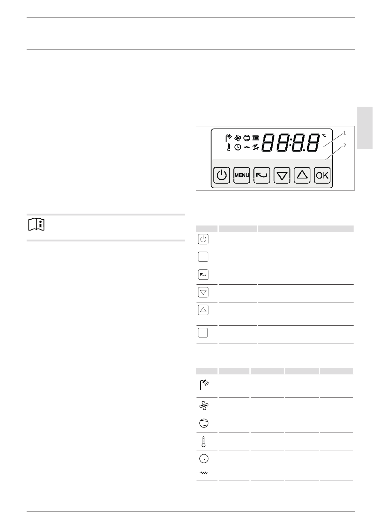
3.4.1 Display
The display consists of a display and programming unit.
1
2
1 Display unit
2 Programming unit
Keys
Button Designation Description
Power button Put the appliance into standby mode or restart
it
ENGLISH
D0000045887
3.2.2 Ambient temperatures above the application limit
The safety equipment switches the appliance off if the upper application limit is exceeded. Following a cooling time of several
minutes the appliance is switched back on automatically. The appliance is switched off again if the intake air temperature rises
back above the permissible temperature value.
To guarantee fault-free operation of the appliance, make sure
you operate the appliance within its application limits (see
chapter "Specification/ Data table").
3.3 Frost protection (air as heat source)
If the intake air temperature is too low, the error message Er57
will appear on the display.
If an immersion heater is installed in the DHW cylinder, it can
continue DHW heating while the fault remains. This requires heat
pump mode to be disabled.
MENU
OK
Menu key
Back button
Down button Scroll through the menu, adjust values,
Up button
OK button
Calling up the controller menu
Return to the previous menu
display the set DHW value
Scroll through the menu, adjust values,
display the optional temperature sensor in the
DHW cylinder (only when display sensor F2 is
connected)
Save settings,
select submenus,
acknowledge error messages
Symbols
Symbol Meaning bright dimmed flashes
DHW heating
Fan mode Fan mode active Fan mode
Compressor Compressor
Setting the
temperature
DHW heating
active
active
Setting the temperature
DHW heating according to time
program
switched off -
Compressor
switched off
-
Pasteurisation
function active
Maintenance
(every 2500
hours run)
-
Electric heater
Setting the
time
rod
Setting the time -
Immersion
heater active
Immersion heater switched off
Time needs resetting
-
www.stiebel-eltron.com WWS 20 | 41
OPERATION
Menu structure
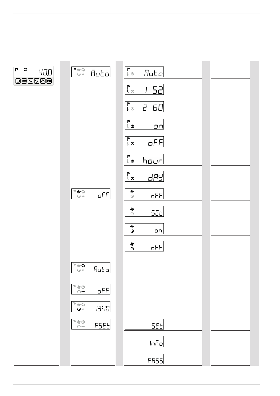
4. Menu structure
Standard display (chapter 4.2)
DHW heating (chapter 4.3)
MENU
▲Fan mode (chapter 4.4)
DHW mode selection (chapter 4.3.1)
OK
Set DHW value (chapter 4.3.2)
▲
Set pasteurisation value (chapter 4.3.3)
▲
DHW start time (chapter 4.3.1)
▲
DHW stop time (chapter 4.3.1)
▲
Pasteurisation function start time (chapter 4.3.3)
▲
Pasteurisation function time interval (chapter 4.3.3)
▲
Fan mode selection (chapter 4.4)
OK
Auto* = Automatic mode
OK
FASt = Quick heat-up
0...60
OK
(52*)
0...60*
OK
00:00*...23:59
OK
00:00...23:59*
OK
00:00*...23:59
OK
0*...14
OK
(0 = Pasteurisation function disabled)
oFF* = Fan switched off
OK
on = Continuous mode
Auto = Automatic mode
▲▼
▲▼
▲▼
▲▼
▲▼
▲▼
▲▼
▲▼
Heat pump mode selection
▲
(chapter 4.5)
Immersion heater mode se-
▲
lection (chapter 4.7)
Time (chapter 4.8)
▲
▲Parameter level (chapter 4.9)
Fan speed (chapter 4.4)
▲
Fan start time (chapter 4.4)
▲
Fan stop time (chapter 4.4)
▲
OK
OK
OK
Parameter setting (chapter 4.9.1)
OK
Call up operating data (chapter 4.9.2)
▲
→
→
→
1...9*
OK
00:00*...23:59
OK
00:00...23:59*
OK
oFF = Compressor
switched off
Auto* = Automatic mode
dEFr = Manual defrosting
oFF* = Immersion heater
switched off
Auto = Automatic mode
00:00...23:59
▲▼
▲▼
▲▼
▲▼
▲▼
▲▼
▲Enter password
11 /34
* Factory setting
42 | WWS 20 www.stiebel-eltron.com
OPERATION
Menu structure
MENU Menu key
OK OK button
▲ Up button
▼ Down button
Press the Back button to go from one menu level to the high-
er menu level.
4.1 Switching on heat pump
Keep the power button pressed for 2seconds.
The standard display appears.
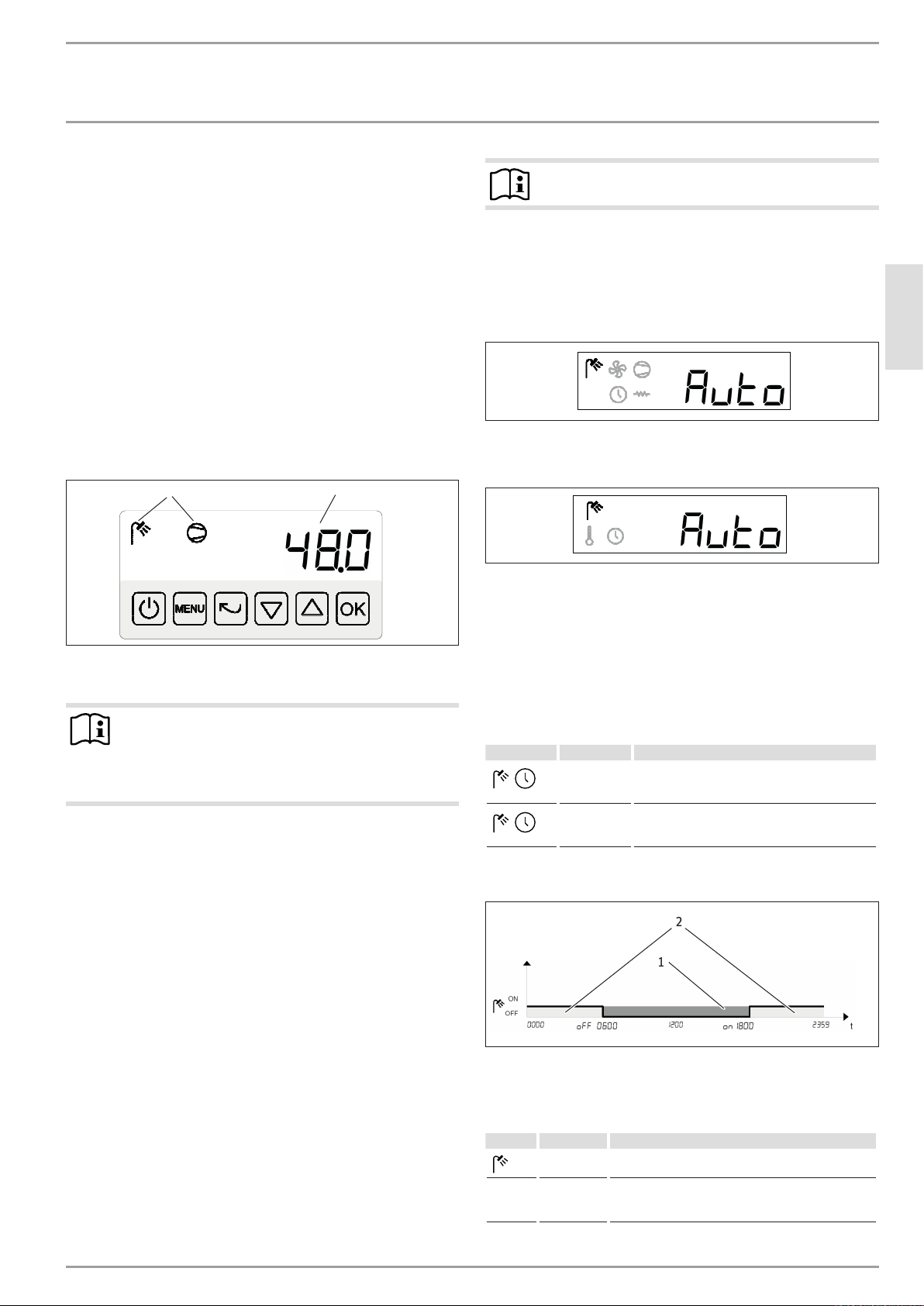
4.2 Standard display
When you are not navigating through the menu structure, the
standard display will be shown. The standard display shows the
actual temperature inside the DHW cylinder (control sensor F1)
and the current operating state of the appliance.
1
1 Operating state
2 Temperature inside the DHW cylinder
2
Note
Automatic mode is the default factory setting.
DHW heating mode setting
You are in the standard display.
Press the Menu button.
The DHW heating submenu appears.
Press the OK button.
The DHW mode selection submenu appears.
Press the OK button.
The operating mode flashes.
Set the required operating mode using the Up/Down buttons.
D0000045843
Confirm your entry with the OK button.
Keep pressing the Back button to return to the standard
display.
ENGLISH
D0000045844
D0000045845
Note
While you are in the standard display, the Up and Down
buttons function like short-cut buttons to call up the current set DHW value and, if display sensorF2 is connected,
the current actual temperature in the DHW cylinder.
4.3 DHW heating
The water in the DHW cylinder is heated up if:
- There is a current demand for domestic hot water
- DHW heating is not blocked by the time program
There is a current demand for domestic hot water when the water
temperature in the DHW cylinder is 5K lower than the selected
set DHW value.
4.3.1 DHW mode selection
The appliance features two different operating modes for DHW
heating:
- Automatic mode
- Quick heat-up
In automatic mode, DHW heating is controlled via an individually
adjustable time program. The DHW is heated using all the heat
sources which are enabled for automatic mode (see chapter "Parameter level/ Parameter setting").
In quick heat-up mode, the water is heated immediately to the
selected set DHW value, irrespective of automatic mode. Once the
selected set DHW value has been reached, the appliance switches
back to automatic mode.
Automatic mode time program setting
Symbol Parameter Description
on
off
DHW start time:
The time when DHW heating is enabled (factory
setting = 00:00)
DHW stop time:
The time when DHW heating is blocked (factory
setting = 23:59)
Example: DHW heating is blocked between 06:00-18:00
2
1
1 DHW heating enabled
2 DHW heating blocked
Quick heat-up activation and setting
Symbol Parameter Description
FASt Once-only quick heat-up starts as soon as "FASt" is
PSEt
└ SEt
b03
set.
Select the heat source for quick heat-up
0 = Heat pump only (factory setting)
1 = Heat pump and immersion heater
D0000045896
www.stiebel-eltron.com WWS 20 | 43
OPERATION
Menu structure
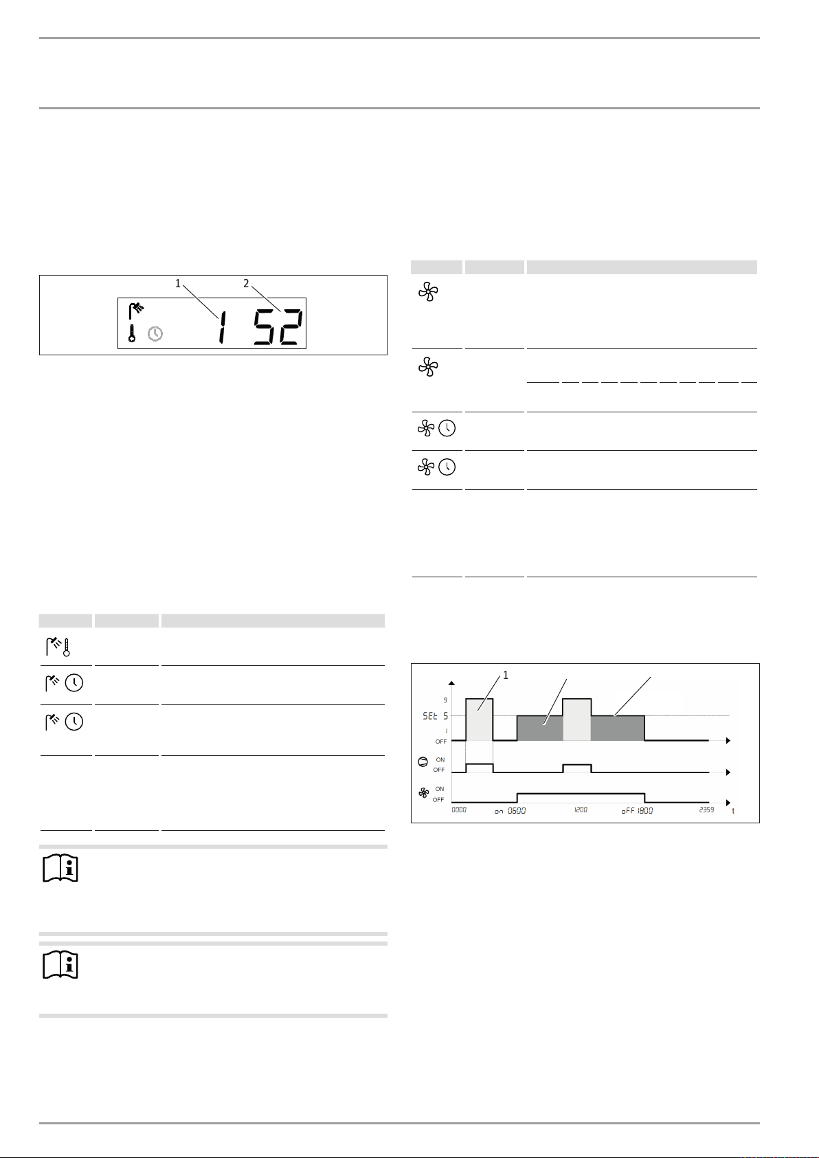
4.3.2 DHW value setting
You are in the standard display.
Press the Menu button.
The DHW heating submenu appears.
Press the Up button.
The set DHW value submenu appears.
1 2
1 Set DHW value display (set value1)
2 Current set DHW value
Press the OK button to confirm your selection.
The set DHW value flashes.
Set the required DHW value using the Up/Down buttons.
Confirm your entry with the OK button.
Keep pressing the Back button to return to the standard
display.
4.3.3 Pasteurisation function
The pasteurisation function is used to meet hygiene requirements. It is implemented using the heat pump and other active
heat sources. The DHW cylinder is heated periodically to the set
pasteurisation value (set value2).
Symbol Parameter Description
2 60
hour
Set pasteurisation value: Set temperature in the
DHW cylinder for the pasteurisation function (factory setting = 60°C)
Pasteurisation function start time
(factory setting = 00:00)
4.4 Fan mode
The fan can be switched on irrespective of the heat pump mode.
For this fan mode, you can set the fan speed and a time program.
Alternatively, the fan can be switched on and off via an external
switching input.
Fan mode setting
Symbol Parameter Description
D0000045846
(factory setting = 9)
PSEt
└ SEt
* The fan stage data is based on a freely blowing appliance
Example switching diagram:
Auto
SEt
on
oFF
A04
Fan mode selection
oFF = Fan switched off (factory setting)
on = Fan operating at rated speed, compressor
active
Auto = Automatic mode (fan operating via separate
time program)
Fan speed (automatic mode)
Stage* 0 1 2 3 4 5 6 7 8 9
% 0 45 60 71 81 89 94 98 99 100
Fan start time (automatic mode)
(factory setting = 00:00)
Fan stop time (automatic mode)
(factory setting = 23:59)
Function of switching input E3
0 = No function (factory setting)
3 = External fan control:
K3 open = Fan switched off, no DHW demand
K3 closed = Fan operates at set speed
with no external air routing lines.
1 3
2
PSEt
└ SEt
dAY
b02
Pasteurisation function time interval: The time
interval during which the pasteurisation function
is periodically implemented
(factory setting = 0)
Maximum pasteurisation function heat-up time: If
the set pasteurisation value is not achieved within
the time set here, the heat-up process is terminated (see chapter "Parameter level/ Parameter
setting").
(factory setting = 4.0h)
Note
The pasteurisation function may be influenced by the
DHW heating time program.
Set the pasteurisation function start time in the peri-
od where DHW heating is enabled.
Note
If the power supply has been interrupted, e.g. following a
power failure, the selected heat-up time can be extended
up to 6hours.
D0000045897
1 Compressor active (light grey)
2 Fan operating at rated speed
3 Compressor switched off (dark grey)
4 Fan in automatic mode, independently of compressor
5 Fan stage curve
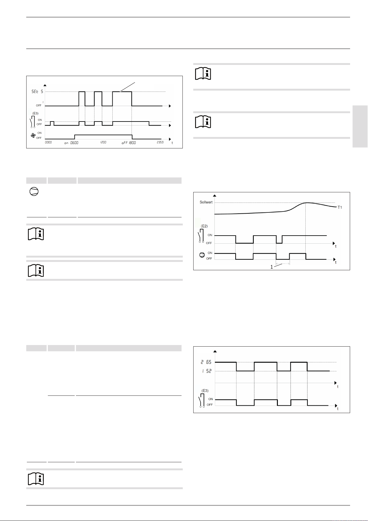
4.4.1 External fan control
Alternatively, the fan can be switched on and off from an external
control unit via switching input E3 (see chapter "Junction box").
To do this, fan mode selection must be set to "Auto". The time
program for fan mode takes priority over the external fan control,
so switching inputE3 is active only while fan mode is enabled.
44 | WWS 20 www.stiebel-eltron.com
OPERATION
Menu structure
Example switching diagram:
1 Fan speed curve
4.5 Heat pump mode selection
Symbol Parameter Description
Auto
Heat pump mode selection
oFF = Compressor switched off
Auto = Automatic mode (according to the period
DHW heating is enabled)
defr = Manual defrosting of the compressor
(factory setting = Auto)
Note
When the heat pump compressor is switched off, the fan
operates in automatic mode. The heat pump does not
provide any DHW heating.
Note
1
An external shutdown takes priority over increasing the
set value.
4.6.1 Power supply utility shutdown
Note
Shutting down the heat pump power supply utility has
no effect on ventilation.
D0000045898
The heat pump shuts down automatically when:
ENGLISH
- Switching input E2 is open
- The set value for DHW temperature has been reached
The display shows the word StOP.
Example switching diagram:
Note
The heat pump is set to automatic mode at the factory.
4.6 Operation with external signal transmitter
You can switch off the heat pump or set it to a higher set value
using floating switching inputsE2 and E3 (see chapter "Junction
box").
You can configure E2 and E3 via the "Parameter setting" submenu
as follows:
Symbol Parameter Description
PSEt
└ SEt
A03
A04
Function of switching input E2
0 = No function (factory setting)
1 = Power supply utility shutdown:
K2 open = Heat pump (and immersion heater)
switched off
K2 closed = Heat pump is running
Function of switching input E3
0 = No function (factory setting)
1 = Power supply utility shutdown:
K2 open = Heat pump (and immersion heater)
switched off
K2 closed = Heat pump is running
2 = Smart Grid function:
K3 open = DHW set value is delivered
K3 closed = Pasteurisation set value is delivered
1
T1 Temperature in the DHW cylinder (sensor F1)
1 Minimum compressor idle time (20min)
4.6.2 Set value increase
If you have your own photovoltaic system, you can increase the
delivered set value via switching input E3 when you have a low
electricity tariff. This will then deliver the pasteurisation set value
(2) instead of the DHW set value (1).
Example switching diagram:
D0000045900
D0000045901
Note
The compressor has a minimum idle time of 20minutes.
www.stiebel-eltron.com WWS 20 | 45