

STIEBEL ELTRON WWK 222, WWK 222 H, WWK 302, WWK 302 H Operation And Installation Manual
OPERATION AND INSTALLATION
DHW heat pump
» WWK222
» WWK222H
» WWK302
» WWK302H

2 | WWK222-302 H www.stiebel-eltron.com
CONTENTS
SPECIAL INFORMATION
OPERATION
1. General information �����������������������������������������4
1.1 Safety instructions ����������������������������������������������� 4
1.2 Other symbols in this documentation ����������������������� 4
1.3 Units of measurement ������������������������������������������ 4
2. Safety ���������������������������������������������������������� 4
2.1 Intended use ������������������������������������������������������ 4
2.2 General safety instructions ������������������������������������ 4
2.3 Test symbols ������������������������������������������������������ 5
3. Appliance description ���������������������������������������5
3.1 Heat pump operating principle ������������������������������� 6
3.2 DHW heating ������������������������������������������������������ 6
3.3 Appliance operation outside the application limits ������� 6
3.4 Frost protection �������������������������������������������������� 6
3.5 Minimum runtime and minimum pause time �������������� 7
3.6 Connection of an external signal transmitter �������������� 7
4. Settings �������������������������������������������������������7
5. Cleaning, care and maintenance ���������������������������7
6. Troubleshooting ����������������������������������������������9
INSTALLATION
7. Safety �������������������������������������������������������� 10
7.1 General safety instructions ����������������������������������� 10
7.2 Instructions, standards and regulations ������������������� 10
8. Appliance description ������������������������������������� 10
8.1 Standard delivery ����������������������������������������������� 10
8.2 Required accessories ������������������������������������������10
8.3 Further accessories��������������������������������������������� 10
8.4 Incorrect use ����������������������������������������������������� 10
9. Preparations ������������������������������������������������ 10
9.1 Transport ��������������������������������������������������������� 10
9.2 Storage ������������������������������������������������������������ 11
9.3 Installation site �������������������������������������������������� 11
9.4 Siting the appliance �������������������������������������������� 12
10. Installation �������������������������������������������������� 13
10.1 Water connection ����������������������������������������������� 13
10.2 Condensate drain ����������������������������������������������� 14
10.3 Power supply ���������������������������������������������������� 14
10.4 Assembling the appliance ������������������������������������ 17
11. Commissioning ��������������������������������������������� 18
11.1 Initial start-up ��������������������������������������������������� 18
11.2 Recommissioning ����������������������������������������������� 18
12. Shutdown ��������������������������������������������������� 18
13. Troubleshooting �������������������������������������������� 19
13.1 Resetting the safety pressure limiter ����������������������� 19
13.2 Resetting the high limit safety cut-out (only WWKH) ��� 19
13.3 Motor overload relay ������������������������������������������� 19
14. Maintenance ������������������������������������������������ 20
14.1 Removing the appliance cover ������������������������������� 20
14.2 Removing the casing ring ������������������������������������� 20
14.3 Cleaning the evaporator ��������������������������������������� 20
14.4 Draining the cylinder ������������������������������������������ 21
14.5 Descaling the electric emergency/booster heater ������� 21
14.6 Valves ������������������������������������������������������������� 21
14.7 Condensate drain ����������������������������������������������� 21
14.8 Replacing the power cable ����������������������������������� 21
14.9 Fitting the casing ring ����������������������������������������� 21
14.10 Fitting the appliance cover ����������������������������������� 21
15. Specification ������������������������������������������������ 22
15.1 Dimensions and connections ��������������������������������� 22
15.2 Wiring diagram ������������������������������������������������� 24
15.3 Data table �������������������������������������������������������� 26
WARRANTY
ENVIRONMENT AND RECYCLING

ENGLISH
www.stiebel-eltron.com WWK222-302 H | 3
SPECIAL INFORMATION
SPECIAL INFORMATION
- The appliance may be used by children aged 8
and older and persons with reduced physical,
sensory or mental capabilities or a lack of experience and know-how, provided that they are
supervised or they have been instructed on how
to use the appliance safely and have understood
the resulting risks. Children must never play with
the appliance. Children must never clean the appliance or perform user maintenance unless they
are supervised.
- Observe all applicable national and regional regulations and instructions.
- Observe the minimum clearances (see chapter "Installation/ Preparations/ Siting the
appliance").
- Observe the requirements concerning the installation room (see "Specification/ Data table").
- The connection to the power supply must be
in the form of a permanent connection. Ensure
the appliance can be separated from the power
supply by an isolator that disconnects all poles
with at least 3mm contact separation. Contactors, circuit breakers or fuses can be used for
this. This type of isolator must be installed in the
fixed electrical installation according to the wiring
rules. For Australia: Ensure that the appliance can
be separated from the power supply by a suitable
isolator. Contactors, circuit breakers or fuses can
be used for this. This type of isolator must be installed in accordance with the wiring rules.
- Observe the safety measures to prevent contact
with dangerous 'live' currents.
- Observe the MCB/fuse protection required for
the appliance (see chapter "Specification/ Data
table").
- If the power cable is faulty, replace it with a new
one. The power cable must only be replaced (for
example if damaged) by a qualified contractor.
- The appliance is pressurised. During the heat-up
process, expansion water will drip from the safety
valve.
- Activate any valves at least once every 6months
to prevent blockages, e.g. by limescale deposits.
- Drain the appliance as described in "Installation/ Maintenance and cleaning/ Draining the
cylinder".
- A T&P valve or a safety valve (cold water expansion control valve) must be installed. Observe all
applicable national and regional regulations and
instructions.
- The maximum pressure in the cold water supply
line must be at least 20% below the response
pressure of the lowest pressure rated valve installed, otherwise a pressure reduction valve will
be required. If this is the case, install a pressure
reduction valve in the cold water feed. The pressure reducing valve must be set to 440kPa if a
safety valve is installed; otherwise to 550kPa.
- Fit the discharge pipe of the safety valve with
a constant downward slope and in a room free
from the risk of frost.
- Size the drain so that water can drain off unimpeded when the safety valve is fully opened.
- The safety valve discharge aperture must remain
open to atmosphere.
OPERATION
General information
4 | WWK222-302 H www.stiebel-eltron.com
OPERATION
1. General information
The chapters "Special Information" and "Operation" are intended
for both the user and qualified contractors.
The chapter "Installation" is intended for qualified contractors.
Note
Read these instructions carefully before using the appliance and retain them for future reference.
Pass on the instructions to any new user where appropriate.
1.1 Safety instructions
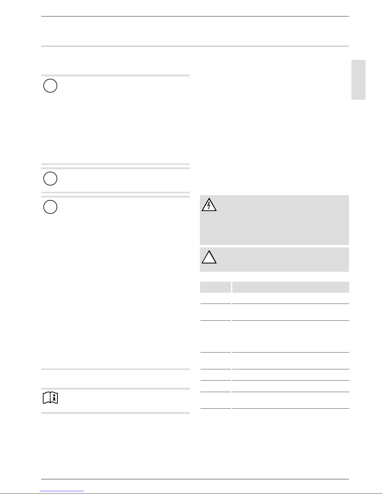
1.1.1 Structure of safety instructions
!
KEYWORD Type of risk
Here, possible consequences are listed that may result
from failure to observe the safety instructions.
Steps to prevent the risk are listed.
1.1.2 Symbols, type of risk
Symbol Type of risk
Injury
Electrocution
Burns
(burns, scalding)
1.1.3 Keywords
KEYWORD Meaning
DANGER Failure to observe this information will result in serious
injury or death.
WARNING Failure to observe this information may result in serious
injury or death.
CAUTION Failure to observe this information may result in non-seri-
ous or minor injury.
1.2 Other symbols in this documentation
Note
General information is identified by the adjacent symbol.
Read these texts carefully.
Symbol Meaning
Material losses
(appliance damage, consequential losses and environmental pollution)
Appliance disposal
This symbol indicates that you have to do something. The ac-
tion you need to take is described step by step.
1.3 Units of measurement
Note
All measurements are given in mm unless stated otherwise.
2. Safety
2.1 Intended use
The purpose of this appliance is to heat domestic hot water within
the application limits stated in the chapter "Specification / data
table".
This appliance is intended for domestic use. It can be used safely
by untrained persons. The appliance can also be used in a non-domestic environment, e.g.in a small business, as long as it is used
in the same way.
Any other use beyond that described shall be deemed inappropriate. Observation of these instructions and of instructions for any
accessories used is also part of the correct use of this appliance.
2.2 General safety instructions
Operate the appliance only when fully installed and with all safety
equipment fitted.
!
WARNING Injury
The appliance may be used by children aged 8 and older
and persons with reduced physical, sensory or mental
capabilities or a lack of experience and know-how, provided that they are supervised or they have been instructed on how to use the appliance safely and have
understood the resulting risks. Children must never play
with the appliance. Children must never clean the appliance or perform user maintenance unless they are
supervised.
WARNING Electrocution
Contact with live components presents a threat to life.
Damage to the cable insulation or to individual components may result in a risk to life.
If there is damage to the insulation, switch off the
power supply and arrange a repair.
All work on the electrical installation must be carried
out by a qualified contractor.
!
!
OPERATION
Appliance description
ENGLISH
www.stiebel-eltron.com WWK222-302 H | 5
WARNING Burns
The water in the DHW cylinder can be heated to temperatures in excess of 60°C. There is a risk of scalding at
outlet temperatures in excess of 43 °C.
Ensure you do not come into contact with the water
when discharged.
WARNING Burns
Touching hot components can lead to burns.
When working on hot components, always wear
protective working clothing and safety gloves.
The pipework connected to the DHW outlet of the appliance can reach temperatures in excess of 60°C.
WARNING Burns
The appliance is filled with refrigerant at the factory.
In the event of refrigerant escaping due to a leak, avoid
coming into contact with the refrigerant or inhaling the
released vapours. Ventilate the rooms affected.
WARNING Electrocution
Never operate the appliance when the casing is open or
without a cover.
!
CAUTION Injury
If objects are left on the appliance, noise emissions may
increase due to resulting vibrations, and the objects
could fall and cause injury.
Never place any objects on top of the appliance.
!
Material losses
At the factory, the appliance is fitted with rechargeable
batteries that ensure the power supply to the impressed
current anode in the case of a power failure.
To enable the impressed current anode to provide protection against corrosion, the power supply to the appliance must not be interrupted for more than 16 hours if
the DHW cylinder is filled with water and the anode is
not connected separately to a continuous power supply
source.
If regular interruptions to the power supply are not anticipated, the batteries will require no maintenance.
Every three years, you must replace the batteries for the
impressed current anode in the following cases:
- The impressed current anode is not connected separately to a continuous power supply source and
a switching contact regularly interrupts the power
supply to the appliance.
- The security of supply is inadequate.
Neglecting to do this puts the appliance at risk of damage.
Never use batteries that cannot be charged. Only nickel-metal hydride (Ni-MH) rechargeable batteries are
permissible.
Batteries may be damaged in the appliance. Without a
power supply, the impressed current anode and the cylinder would not be protected against corrosion.
!
Material losses
Ensure that the appliance, the water pipes and safety
valves are free from any risk of frost. If you disconnect the
appliance from the power supply, it is no longer protected
against frost.
!
Material losses
Never cover the appliance. Covering the air intake or air
discharge leads to a reduced air supply. If the air supply
is restricted, the operational reliability of the appliance
cannot be guaranteed.
!
Material losses
Only operate the appliance when the DHW cylinder has
been filled. If the DHW cylinder is empty, safety equipment switches off the appliance.
!
Material losses
Heating liquids other than potable water is not permitted.
!
Material losses
Keep the appliance installation site free from air contaminated with oil or salt (chloride) and corrosive or explosive substances. Avoid contaminating the installation site
with dust, hairspray or substances containing chlorine
or ammonia.
!
Material losses
Operating the appliance outside the application limits
(see "Specification/ Data table") is not permitted. The
appliance may be damaged if operated continuously outside the application limits.
Note
The appliance is pressurised. During the heat-up process,
expansion water will drip from the safety valve.
If water continues to drip when heating is complet-
ed, inform your qualified contractor.
2.3 Test symbols
See type plate on the appliance.
3. Appliance description
This appliance enables DHW to be supplied efficiently to several
draw-off points using renewable energy. The appliance extracts
heat from the ambient air. This heat is used to heat up the water
in the DHW cylinder with added electric power. The amount of
electrical energy and time required to heat up the DHW depend
on the temperature of the air drawn in. When the air inlet temperature drops, the appliance output is reduced and the heat-up
time is extended.
Subject to the power supply and user draw-off behaviour, the
water is heated automatically to the selected set temperature. The
appliance heats up the water to a temperature which is selected
at the factory.
OPERATION
Appliance description
6 | WWK222-302 H www.stiebel-eltron.com
In the case of indoor installation, the air inside the installation
room can be cooled by 1°C to 3°C through heat extraction. The
appliance also extracts moisture from the air, which turns into
condensate. The condensate is removed from the appliance via
the condensate drain.
When a hot water draw-off point is opened, the hot DHW is pushed
out of the appliance by the inflow of cold water.
The heat pump drive unit is located in the upper section of the
appliance. The DHW cylinder is located in the lower section of the
appliance. To protect against corrosion, the DHW cylinder is coated
internally with special enamel and is additionally equipped with
an impressed current anode.
3.1 Heat pump operating principle
A closed circuit within the appliance contains refrigerant (see
"Specification/ Data table"). This refrigerant evaporates at low
temperatures. In the evaporator, which extracts heat from the
air drawn in, the refrigerant changes from a liquid into a gaseous state. A compressor draws in the gaseous refrigerant and
compresses it. This increase in pressure raises the refrigerant
temperature. That requires electrical energy.
The energy (motor heat) is not lost, but reaches the downstream
condenser together with the compressed refrigerant. There, the
refrigerant transfers heat to the DHW cylinder. An expansion valve
then reduces the still prevalent pressure and the cyclical process
starts again.
3.2 DHW heating
2
1
D0000050335
1 Cylinder top sensor
2 Integral sensor
The appliance is equipped with two temperature sensors.
- The cylinder top sensor captures the water temperature in
the upper section of the cylinder.
- The integral sensor is a temperature sensor affixed over the
entire cylinder height. The integral sensor determines the
average cylinder temperature.
The appliance control unit uses the average cylinder temperature
captured by the integral sensor. DHW heating is started when
the average cylinder temperature has fallen below the set temperature.
DHW is normally heated by the heat pump of the appliance (see
chapter "Specification/ Data table").
Note
If the appliance has been isolated from the power supply
during operation, the compressor will only restart after
the pressure inside the refrigerant circuit has been equalised. Pressure compensation can take several minutes.
WWK222H|WWK302H: Electric emergency/booster heater
When the temperature in the upper section of the DHW cylinder
drops 10K below the selected set temperature, the appliance
automatically switches on the electric emergency/booster heater.
When the temperature in the upper section of the DHW cylinder
rises 2K above the selected set temperature, the appliance switches off the electric emergency/booster heater.
3.3 Appliance operation outside the application
limits
3.3.1 Ambient temperatures below the application limit
Outside the application limits, the appliance disables the compressor operation. This could lead to reduced DHW convenience.
If the appliance has an electric emergency/booster heater, this
will be enabled if a demand for heating up the water exists and
the lower application limit is underrun.
Low ambient temperatures may result in the formation of hoar
frost on the evaporator depending on the air humidity and water
temperature.
Active defrost feature
The appliance is equipped with active hot gas defrosting, which
allows quick defrosting of the evaporator when needed. During
defrosting, the appliance fan is disabled and the compressor continues to run. A solenoid valve routes the hot gas directly to the
evaporator. While this is happening, the condenser is disabled by
another solenoid valve.
In contrast to conventional defrosting methods, the appliance
guarantees that defrosting takes place only when needed.
Note
Heat-up times are longer while the evaporator is defrosting.
3.3.2 Ambient temperatures above the application limit
Outside the application limits, the appliance disables the compressor operation. This could lead to reduced DHW convenience.
If the appliance has an electric emergency/booster heater, this
will be enabled if a demand for heating up the water exists and
the lower application limit is underrun.
3.4 Frost protection
The appliance activates the frost protection function if the integral
sensor in the DHW cylinder captures a temperature below 10°C.
The appliance then heats the water by means of the heat pump
and the electric emergency/booster heater. The heat pump and
electric emergency/booster heater switch off when the temperature captured by the integral sensor reaches 18°C.
OPERATION
Settings
ENGLISH
www.stiebel-eltron.com WWK222-302 H | 7
3.5 Minimum runtime and minimum pause time
!
Material losses
When operating with external switching devices that can
interrupt the power supply to the appliance, such as time
switches, energy management systems or home automation systems, observe the following conditions:
- The minimum ON time is 60 minutes.
- The minimum pause time following a shutdown is
20 minutes.
- The appliance should not be switched on/off more
than 10 times per day.
- The breaking capacity of the switching element must
meet the fuse rating requirements (see chapter
“Specification/ Data table”).
!
Material losses
If you disconnect the appliance from the power supply, it
is no longer protected against frost.
!
Material losses
At the factory, the appliance is fitted with rechargeable
batteries that ensure power supply to the impressed current anode in the case of a power failure.
To enable the impressed current anode to provide protection against corrosion, the power supply to the appliance must not be interrupted for more than 16 hours if
the DHW cylinder is filled with water and the annode is
not connected separately to a continuous power supply
source.
If regular interruptions to the power supply are not anticipated, the batteries will require no maintenance.
Every three years, you must replace the batteries for the
impressed current anode in the following cases:
- The impressed current anode is not connected separately to a continuous power supply source and
a switching contact regularly interrupts the power
supply to the appliance.
- The security of supply is inadequate.
Neglecting to do this puts the appliance at risk of damage.
Never use batteries that cannot be charged. Only nickel-metal hydride (Ni-MH) rechargeable batteries are
permissible.
Batteries may be damaged in the appliance. Without a
power supply, the impressed current anode and the cylinder would not be protected against corrosion.
3.6 Connection of an external signal transmitter
Note
This type of connection must only be carried out by a
qualified electrician.
External signal transmitters can be integrated via the built-in contact input, e.g. a PV system to make use of solar power generated
on site.
The appliance has a second set temperature preselected at the factory. This is activated in the event of an external switching signal.
Set temperature2 takes priority over the standard set temperature
while there is an external switching signal.
Following a one-off activation (signal is present for at least 1minute), set temperature2 applies for at least 20minutes and is ranked
higher than set temperature1.
The qualified contractor can use software to change set temperature2 with an accessory available from us.
4. Settings
Adjustments are not necessary. The DHW temperature has been
set at the factory.
Emergency shutdown
In the event of an emergency, carry out the following steps:
Disconnect the appliance from the mains at the MCB/fuse in
the fuse box.
Shut off the cold water supply.
5. Cleaning, care and maintenance
WARNING Electrocution
- Only clean the exterior of the appliance.
- Never open the appliance.
- Do not insert objects through the grills into the inte-
rior of the appliance.
- Never spray the appliance with water.
- Never spray water into the appliance.
!
WARNING Injury
Maintenance work, such as checking electrical safety,
must only be carried out by a qualified contractor.
Appliance
components
Care and maintenance t ips
Casing Use a damp cloth to clean the casing sections. Never use
abrasive or corrosive cleaning agents.
Air intake
grille/ air discharge grille
Clean the air intake grille and air discharge grille every six
months. Cobwebs or other kinds of contamination could obstruct the air supply to the appliance.
DHW cylinder
The DHW cylinder is equipped with a maintenance-free
impressed current anode to safeguard it against corrosion.
The power supply must not be interrupted for more than 16
hours while the DHW cylinder is filled with water to enable
the impressed current anode to provide protection against
corrosion.
Electric emergency/booster
heater
Have the electric emergency/booster heater descaled from
time to time. This will ex tend the service life of the electric
emergency/booster heater.
Safety equipment
Activate any valves at least once every 6months to prevent
blockages, e.g. by limescale deposits.
Evaporator Have the evaporator checked regularly by a qualified contrac-
tor.
Condensate
drain
Undo the condensate drain. Check that the condensate drain
is clear and remove any dirt from the condensate drain connection.
OPERATION
Cleaning, care and maintenance
8 | WWK222-302 H www.stiebel-eltron.com
Protective anode and battery replacement
The appliance is equipped with a maintenance-free, impressed
current anode that protects the tank from corrosion while it is
supplied with power. At the factory, the appliance is fitted with
rechargeable batteries that ensure the power supply to the impressed current anode in the case of a power failure. The power
supply may be interrupted for up to 16 hours.
If the power supply is regularly interrupted by a switching contact or the security of supply is inadequate, the batteries of the
impressed current anode must be replaced every three years. Neglecting to do this puts the appliance at risk of damage. If regular
interruptions in the power supply are not anticipated and there
is security of supply, no maintenance of the batteries is required
and the appliance is maintenance-free in this regard.
!
Material losses
Never use batteries that cannot be charged. Only rechargeable batteries are permissible.
Batteries may be damaged in the appliance. Without a
power supply, the impressed current anode and the cylinder would not be protected against corrosion.
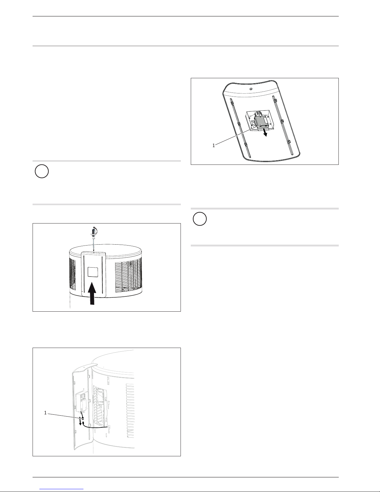
The rechargeable batteries are secured at the back of the fascia.
D0000040621
Undo the screw securing the fascia.
Carefully remove the fascia so that the cables running from
the batteries to the impressed current anode in the appliance
are not pulled out.
D0000051618
1
1 Plug-in connection
Undo the plug-in connection by pressing the connection lock
on both sides.
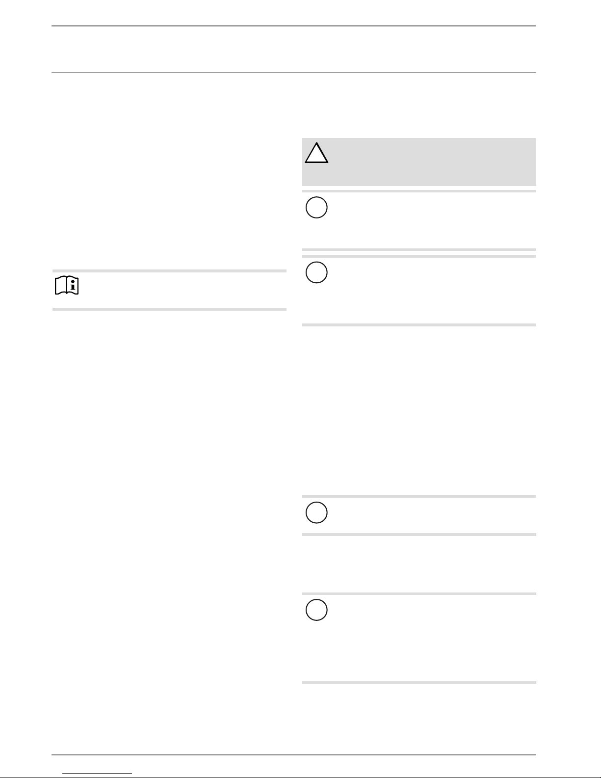
D0000051617
1
1 Battery compartment
Pull the battery compartment down to remove it from the
retainer.
Open the battery compartment using a screwdriver.
Replace the batteries (NiMH, type AAA, ≥800mAh).
!
Material losses
Make sure that the batteries are properly inserted the
right way round, because otherwise there will be no
corrosion protection in the event of interruptions in the
power supply.
Close the battery compartment using a screwdriver.
Push the battery compartment into the retainer.
Reconnect it to the appliance with the plug-in connection.
OPERATION
Troubleshooting
ENGLISH
www.stiebel-eltron.com WWK222-302 H | 9
6. Troubleshooting
Problem Cause
Remedy
No hot water
is available.
No power at the appliance. Check that the appliance is con-
nected to the power supply.
A fuse/MCB in the fuse box
has blown/responded.
Check whether the fuses/MCBs
in your fuse box have blown/
responded. Contact a qualified
contractor if the fuse blows or
the MCB responds again after
the appliance is connected to the
power supply.
The air intake or air discharge
of the appliance is blocked.
Check the air intake grille and
air discharge grille for contamination. Remove any contamination (see chapter "Maintenance
and care").
Outside the application limits, the appliance blocks the
compressor. This could lead to
reduced DHW convenience.
No action required. The appliance will then restart the compressor automatically.
The DHW cylinder is not completely full.
The appliance restarts automatically when the DHW cylinder has
been filled.
Due to a previous high demand for hot water, the unit
has not had the chance to
fully recover.
No action required. Allow the
unit to continue operating normally until the heating cycle is
completed.
The safety pressure limiter
has responded 5 times in
5hours.
Notify a qualified contractor who
will reset the safety pressure
limiter.
A safety valve
is dripping.
These units are under water
mains pressure. During the
heat-up process, expansion
water will drip from a safet y
valve.
If water continues to drip when
heating is completed, please inform your qualified contractor.
The condensate drain
drips.
The surface temperature of
the evaporator is lower than
the dew point temperature of
the ambient air. Condensate
forms.
This is expected and no action
is required. The amount of
condensate depends on the air
humidity level.
For indoor installations the
room temperature drops
too low.
Operation of the appliance can
cause the room temperature to
fall by 1 to 3°C. If the room temperature falls by more than 5°C,
check the room size (see chapter
"Specification/Data table").
Increasing the room size by
opening a door to another room
will remedy this.
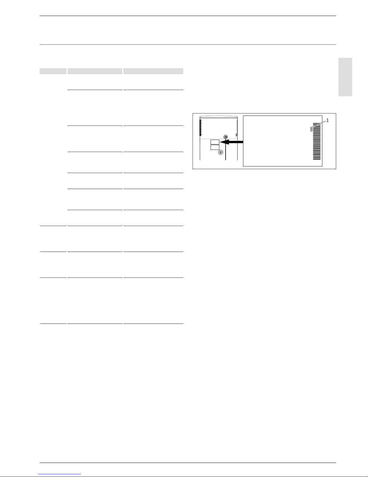
Notifying a qualified contractor
If you cannot remedy the fault, notify your qualified contractor. In
Australia direct notify us (1800153351). To facilitate and speed up
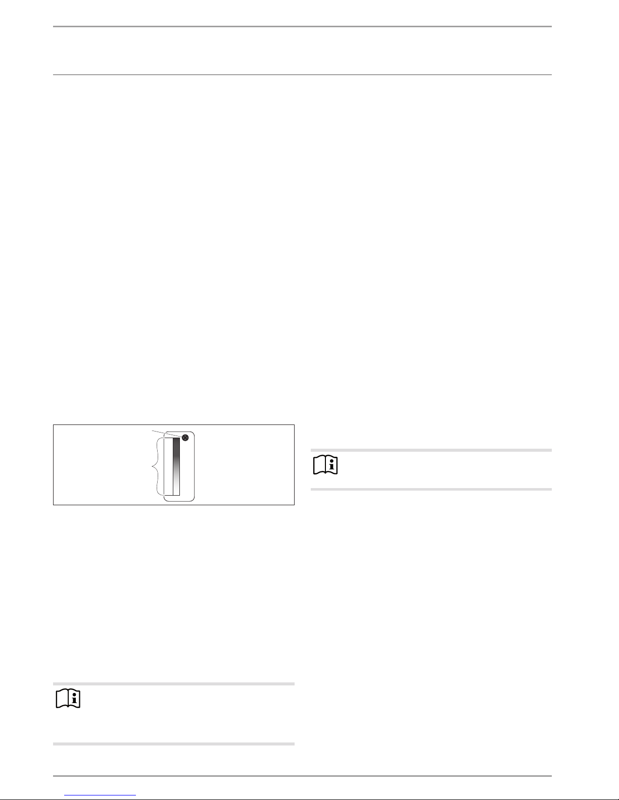
your request, provide the number from the type plate (0000000000-000000). The type plate can be found on the left, above the
DHW outlet connection.
Sample type plate
000000-0000-000000
D0000035352
1
1 Number on the type plate
10 | WWK222-302 H www.stiebel-eltron.com
INSTALLATION
Safety
INSTALLATION
7. Safety
Only a qualified contractor should carry out installation, commissioning, maintenance and repair of the appliance.
7.1 General safety instructions
We guarantee trouble-free function and operational reliability only
if original accessories and spare parts intended for the appliance
are used.
7.2 Instructions, standards and regulations
Note
Observe all applicable national and regional regulations
and instructions.
Take note of the appliance type plate and chapter "Specification".
8. Appliance description
The heat pump drive unit is located in the upper section of the
appliance. The DHW cylinder is located in the lower section of
the appliance.
8.1 Standard delivery
The following are delivered with the appliance:
- Condensate drain bend
- 2 straight pipe adapters G1 to G3/4 (use subject to type of
installation, see chapter "Preparations/ Siting the appliance/
Minimum clearances") comprising a flanged pipe, a gasket
and a union nut
- 2 135° pipe adapters G1 to G3/4 union nut (use subject to
type of installation, see chapter "Preparations/ Siting the appliance/ Minimum clearances")
8.2 Required accessories
Various safety assemblies are available that need to be selected
subject to the static pressure. These type-tested safety assemblies
protect the appliance against unacceptable excess pressure.
8.3 Further accessories
- Condensate pump (if the condensate cannot be drained off
with a naturally occurring fall)
8.4 Incorrect use
The following are not permitted:
- Operating the appliance when the casing is open
- Filling the appliance with a refrigerant other than the one
detailed in chapter "Specification/ Data table"
- Heating liquids other than potable water
Observe the list of requirements regarding the installation room
and non-permissible installation sites (see chapter "Installation
site").
9. Preparations
9.1 Transpor t
!
CAUTION Injury
Observe the weight of the appliance.
Use suitable transport aids (e.g. a pallet trolley) and
enough personnel for transportation.
!
Material losses
The appliance has a high centre of gravity and low overturning moment.
Safeguard the appliance against falling over.
Only set the appliance down on an even base.
!
Material losses
The appliance casing is not designed to withstand strong
forces. Incorrect handling can lead to material losses of
considerable extent.
Observe the information on the packaging.
Only remove the packaging shortly before the installation.
Where possible, do not unpack the appliance until it has arrived
in the installation room.
For transport and handling leave the appliance in its packaging
and on the pallet. This enables brief horizontal transport and provides places to hold on to during transport.
If the appliance has to be unpacked before transportation, we
recommend using a pallet trolley. Pad the contact surfaces to avoid
damaging the appliance. Secure the appliance to the pallet trolley
using a strap. Pad between the strap and the appliance and avoid
overtightening the strap. Where stair wells are narrow, you can
carry the appliance by the handles on the pallet trolley and the
foot of the appliance.
Vehicular transport
!
Material losses
The appliance must generally be stored and transported
vertically.
A transport lock fitted at the factory to the refrigerant circuit
area inside the appliance enables relatively short transportation
horizontally over a maximum distance of 160km of paved roads.
Strong shocks are not permissible.
!
Material losses
If transported horizontally, the appliance must always be
laid on the shaded side of the box.
The appliance must not remain in a horizontal position
for more than 24hours.
If the appliance was transported horizontally, leave it to
rest in a vertical position for at least one hour before
commissioning.
Observe the information on the packaging.
 Loading...