

STIEBEL ELTRON WWK 221 electronic, WWK 301 electronic, WWK 301 electronic SOL Operation And Installation
OPERATION AND INSTALLATION
DHW heat pump
» WWK 221 electronic
» WWK 301 electronic
» WWK 301 electronic SOL

CONTENTS | SPECIAL INFORMATION
SPECIAL INFORMATION
OPERATION
1. General information �����������������������������������������3
1.1 Safety instructions ����������������������������������������������� 3
1.2 Other symbols in this documentation ����������������������� 4
1.3 Units of measurement ������������������������������������������ 4
1.4 Standardised output data �������������������������������������� 4
2. Safety ���������������������������������������������������������� 4
2.1 Intended use ������������������������������������������������������ 4
2.2 General safety instructions ������������������������������������ 4
2.3 Test symbols ������������������������������������������������������ 5
3. Appliance description ���������������������������������������5
3.1 Heat pump operating principle ������������������������������� 5
3.2 DHW heating ������������������������������������������������������ 6
3.3 Appliance operation outside the application limits ������� 7
3.4 Defrosting ��������������������������������������������������������� 7
3.5 Frost protection �������������������������������������������������� 7
3.6 Minimum runtime and minimum pause time �������������� 7
3.7 Connection of an external signal transmitter �������������� 7
4. Settings �������������������������������������������������������8
4.1 Display and controls ��������������������������������������������� 8
4.2 Settings ������������������������������������������������������������ 9
4.3 "Quick heat-up" key ��������������������������������������������11
4.4 Emergency shutdown ������������������������������������������ 12
5. Maintenance and care ������������������������������������� 12
6. Troubleshooting �������������������������������������������� 12
12. Appliance shutdown ��������������������������������������� 26
13. Troubleshooting �������������������������������������������� 26
13.1 Resetting the high limit safety cut-out ��������������������� 27
13.2 Motor overload relay ������������������������������������������� 27
14. Maintenance and cleaning �������������������������������� 27
14.1 Removing the appliance cover ������������������������������� 27
14.2 Removing the casing ring ������������������������������������� 28
14.3 Cleaning the evaporator ��������������������������������������� 28
14.4 Drain cylinder ��������������������������������������������������� 28
14.5 Descaling the electric emergency/booster heater ������� 28
14.6 Protective anode ������������������������������������������������ 29
14.7 Valves ������������������������������������������������������������� 29
14.8 Condensate drain ����������������������������������������������� 29
14.9 Replacing the power cable ����������������������������������� 29
14.10 Fitting the casing ring �����������������������������������������29
14.11 Fitting the appliance cover ����������������������������������� 29
15. Specification ������������������������������������������������ 30
15.1 Dimensions and connections ��������������������������������� 30
15.2 Wiring diagram ������������������������������������������������� 32
15.3 Data table ��������������������������������������������������������34
GUARANTEE
ENVIRONMENT AND RECYCLING
INSTALLATION
7. Safety �������������������������������������������������������� 15
7.1 General safety instructions ����������������������������������� 15
7.2 Instructions, standards and regulations ������������������� 15
8. Appliance description ������������������������������������� 15
8.1 Standard delivery ����������������������������������������������� 15
8.2 Required accessories ������������������������������������������15
8.3 Additional accessories ����������������������������������������� 15
9. Preparations ������������������������������������������������ 15
9.1 Transport ��������������������������������������������������������� 15
9.2 Storage ������������������������������������������������������������ 16
9.3 Installation site and location of air extraction or air
intake�������������������������������������������������������������� 16
9.4 Siting the appliance �������������������������������������������� 17
10. Installation �������������������������������������������������� 18
10.1 Air duct (optional) ���������������������������������������������� 18
10.2 Water connection ����������������������������������������������� 20
10.3 WWK301 electronicSOL: Connection of an external
heat generator ��������������������������������������������������20
10.4 Condensate drain ����������������������������������������������� 21
10.5 Power supply ���������������������������������������������������� 21
10.6 Assembling the appliance ������������������������������������ 24
11. Commissioning ��������������������������������������������� 24
11.1 Initial start-up ��������������������������������������������������� 24
11.2 Recommissioning ����������������������������������������������� 26
SPECIAL INFORMATION
- The appliance may be used by children aged8
and older and persons with reduced physical,
sensory or mental capabilities or a lack of experience and know-how, provided that they are
supervised or they have been instructed on how
to use the appliance safely and have understood
the potential risks. Children must never play with
the appliance. Children must never clean the appliance or perform user maintenance unless they
are supervised.
- Observe all applicable national and regional regulations and instructions during installation.
- The appliance is not approved for outdoor
installation.
- Observe the minimum clearances (see chapter "Installation/ Preparations/ Siting the
appliance").
2 | WWK 221-301 electronic www.stiebel-eltron.com
SPECIAL INFORMATION | OPERATION
General information
- Observe the requirements concerning the installation room (see chapter "Specification/ Data
table").
- If the appliance is permanently connected to the
power supply, ensure that the appliance can be
separated from the power supply by an isolator
that disconnects all poles with at least 3mm
contact separation. Contactors, mains isolators or
fuses can be used for this.
- Observe the safety measures to prevent contact
with dangerous 'live' currents.
- Observe the MCB/fuse protection required for
the appliance (see chapter "Specification/ Data
table").
- The power cable must only be replaced (for example if damaged) with an original spare part by
a qualified contractor authorised by the manufacturer (connection typeX).
- The appliance's DHW cylinder is pressurised.
During the heat-up process, expansion water will
drip from the safety valve.
- Regularly activate the safety valve to prevent
it from becoming blocked, e.g. by limescale
deposits.
- Drain the appliance as described in chapter "Installation/ Maintenance and cleaning/ Draining
the cylinder".
OPERATION
1. General information
The chapters "Special information" and "Operation" are intended
for both users and qualified contractors.
The chapter "Installation" is intended for qualified contractors.
Note
Read these instructions carefully before using the appliance and retain them for future reference.
Pass on the instructions to a new user if required.
1.1 Safety instructions
1.1.1 Structure of safety instructions
KEYWORD Type of risk
!
Here, possible consequences are listed that may result
from failure to observe the safety instructions.
Steps to prevent the risk are listed.
1.1.2 Symbols, type of risk
Symbol Type of risk
!
Injury
Electrocution
Burns
(burns, scalding)
ENGLISH
- Install a type-tested safety valve in the cold water
supply line.
- The maximum pressure in the cold water supply
line must be at least 20% below the response
pressure of the safety valve. If the maximum
pressure in the cold water supply line is higher,
install a pressure reducing valve.
- Size the drain so that water can drain off unimpeded when the safety valve is fully opened.
- Fit the discharge pipe of the safety valve with
a constant downward slope and in a room free
from the risk of frost.
- The safety valve discharge aperture must remain
open to atmosphere.
1.1.3 Keywords
KEYWORD Meaning
DANGER Failure to observe this information will result in serious
injury or death.
WARNING Failure to observe this information may result in serious
injury or death.
CAUTION Failure to observe this information may result in non-seri-
ous or minor injury.
www.stiebel-eltron.com WWK 221-301 electronic | 3
OPERATION
Safety
1.2 Other symbols in this documentation
Note
General information is identified by the adjacent symbol.
Read these texts carefully.
Symbol Meaning
!
This symbol indicates that you have to do something. The ac-
tion you need to take is described step by step.
These symbols show you the software menu level (in
this example level3).
Material losses
(appliance damage, consequential losses and environmental pollution)
Appliance disposal
1.3 Units of measurement
Note
All measurements are given in mm unless stated otherwise.
1.4 Standardised output data
Explanations to determine and interpret the specified standardised
output data
Standard: EN 16147
The output data specifically mentioned in text, diagrams and
technical datasheets has been calculated according to the test
conditions of the standard shown in the heading of this section.
Generally, these standardised test conditions will not fully meet
the conditions found at the installation site of the system user.
Depending on the chosen test method and the extent to which this
method deviates from the conditions defined in the norm shown in
the heading of this section, any deviations can have a considerable
impact. Additional factors that have an influence on the test values
are the measuring equipment, the system configuration, the age
of the system and the flow rates.
A confirmation of the specified output data can only be obtained
if the conditions applicable to the relevant test match those of the
standard shown in the heading of this chapter.
Any other use beyond that described shall be deemed inappropriate. Observation of these instructions and of the instructions
for any accessories used is also part of the correct use of this
appliance.
2.2 General safety instructions
The appliance should only be operated once it is fully installed
and all safety equipment has been fitted.
WARNING Injury
!
The appliance may be used by children aged8 and older
and persons with reduced physical, sensory or mental
capabilities or a lack of experience and know-how, provided that they are supervised or they have been instructed on how to use the appliance safely and have
understood the potential risks. Children must never play
with the appliance. Children must never clean the appliance or perform user maintenance unless they are
supervised.
WARNING Electrocution
Contact with live components presents a threat to life.
Damage to the insulation or to individual components
may result in a threat to life.
If there is damage to the insulation, switch off the
power supply and arrange a repair.
All work on the electrical installation must be carried
out by a qualified contractor.
WARNING Burns
The water in the DHW cylinder can be heated to temperatures in excess of 60°C. There is a risk of scalding at
outlet temperatures in excess of 43 °C.
Ensure you do not come into contact with the water
when discharged.
WARNING Burns
Touching hot components can lead to burns.
When working on hot components, always wear
protective working clothing and safety gloves.
The pipework connected to the DHW outlet of the appliance can reach temperatures in excess of 60°C.
WARNING Burns
The appliance is filled with refrigerant at the factory.
In the event of refrigerant escaping due to a leak, avoid
coming into contact with the refrigerant or inhaling the
released vapours. Ventilate the rooms affected.
2. Safety
WARNING Electrocution
Never operate the appliance when the casing is open,
without a cover, or without side air connectors.
2.1 Intended use
The purpose of this appliance is to heat domestic hot water within
the application limits stated in the chapter "Specification / data
table".
The appliance is intended for domestic use. It can be used safely
by untrained persons. The appliance can also be used in non-domestic environments, e.g. in small businesses, as long as it is
used in the same way.
4 | WWK 221-301 electronic www.stiebel-eltron.com
CAUTION Injury
!
If objects are left on the appliance, noise emissions may
increase due to resulting vibrations, and the objects
could fall and cause injury.
Never place any objects on top of the appliance.
OPERATION
Appliance description
Material losses
!
Ensure that the appliance, water pipes and safety valves
are free from the risk of frost. If you disconnect the appliance from the power supply, it is no longer protected
against frost or corrosion.
Never interrupt the power supply to the appliance.
Material losses
!
Keep the appliance installation site free from air contaminated with oil or salt (chloride) and corrosive or explosive substances. Avoid contaminating the installation site
with dust, hairspray or substances containing chlorine
or ammonia.
Material losses
!
Covering the air intake or air discharge leads to a reduced
air supply. If the air supply is restricted, the operational
reliability of the appliance cannot be guaranteed.
Never cover the appliance.
Material losses
!
Only operate the appliance when the DHW cylinder has
been filled. If the DHW cylinder is empty, safety equipment switches off the appliance.
Material losses
!
Heating liquids other than potable water is not permitted.
The ambient air can be cooled down by between 1°C and 3°C as a
result of heat extraction in the installation room or the room from
which the air is drawn. The appliance also extracts moisture from
the air, which turns into condensate. The condensate is removed
from the appliance via the condensate drain.
The appliance has an electronic control unit with LC display. You
can select the available amount of mixed water at a temperature
of 40 °C, for example. The electronic control unit makes energy
saving adjustments easier. Subject to the power supply and user
draw-off patterns, the water is heated automatically to the selected set temperature.
When the air intake temperature drops, the appliance output is
reduced and the heat-up time is extended. If the value falls below
the heat pump's lower application limit, e.g. where outdoor air is
drawn in, the electric emergency/booster heater takes over DHW
heating.
External signal transmitters can be integrated via the built-in contact input, e.g. a photovoltaic system to make use of solar power
generated on site.
When a hot water draw-off point is opened, the hot DHW is pushed
out of the appliance by the inflow of cold water.
The heat pump drive unit is fitted in the upper section of the appliance. The DHW cylinder is located in the lower section of the
appliance. To protect against corrosion, the DHW cylinder is coated
internally with special enamel and is additionally equipped with
an impressed current anode.
ENGLISH
Note
The appliance's DHW cylinder is pressurised. During the
heat-up process, expansion water will drip from the safety valve.
If water continues to drip when heating is complet-
ed, please inform your qualified contractor.
2.3 Test symbols
See type plate on the appliance.
3. Appliance description
The fully wired appliance enables DHW to be supplied efficiently
to several draw-off points using renewable energy. The appliance
extracts heat from the intake air. This heat is used to heat up the
water in the DHW cylinder with added electric power. The amount
of electric energy and time required to heat up the DHW depend
on the temperature of the air drawn in. When the air intake temperature drops, the appliance output is reduced and the heat-up
time is extended.
The appliance is designed for indoor installation. The choice of
air intake and discharge on the side or top offers flexibility with
regard to possible installation sites. Accessories are required for
the vertical air intake and/or air discharge.
The appliance can be installed as a recirculation air appliance, thus
making efficient use of any available waste heat from freezers or
other heat sources, for example. Alternatively, air ducts can be
connected to use outdoor air as a heat source or to draw in air
from another room.
Material losses
!
If you disconnect the appliance from the power supply, it
is no longer protected against frost or corrosion.
Never interrupt the power supply to the appliance.
Material losses
!
If outdoor air is used as a heat source when outside temperatures are low, condensate may form on the appliance
if the relative humidity is unusually high, i.e. in excess
of 75% and with a room temperature of 22°C. Such
high relative humidity levels will damage the fabric of the
building and must be prevented by ventilation.
3.1 Heat pump operating principle
A closed circuit within the appliance contains refrigerant (see
"Specification/Data table"). This refrigerant evaporates at low
temperatures.
In the evaporator, which extracts heat from the air drawn in, the
refrigerant changes from a liquid into a gaseous state. A compressor draws in the gaseous refrigerant and compresses it. This
increase in pressure raises the refrigerant temperature. That requires electrical energy. The energy (motor heat) is not lost, but
reaches the downstream condenser together with the compressed
refrigerant. There, the refrigerant indirectly transfers heat to the
DHW cylinder. An expansion valve then reduces the still prevalent
pressure and the cycle starts again.
If a compressor is required, the appliance does not start the
compressor immediately; only once the fan's initial runtime has
elapsed. During the fan's initial runtime the appliance checks if all
the conditions required to start the compressor have been met.
www.stiebel-eltron.com WWK 221-301 electronic | 5
OPERATION
1
Appliance description
Note
Following an interruption of the power supply, the
compressor operation remains blocked for at least one
minute. The PCB delays electronic starting by a minute,
during which the appliance goes through its initialising
process.
If the compressor subsequently fails to start, it may be
locked out by additional safety devices (motor overload
relay or high pressure switch). This block should lift after
1 to 10 minutes.
After the power supply has been re-established, the appliance continues to operate with the parameters that
were selected before the power supply was interrupted.
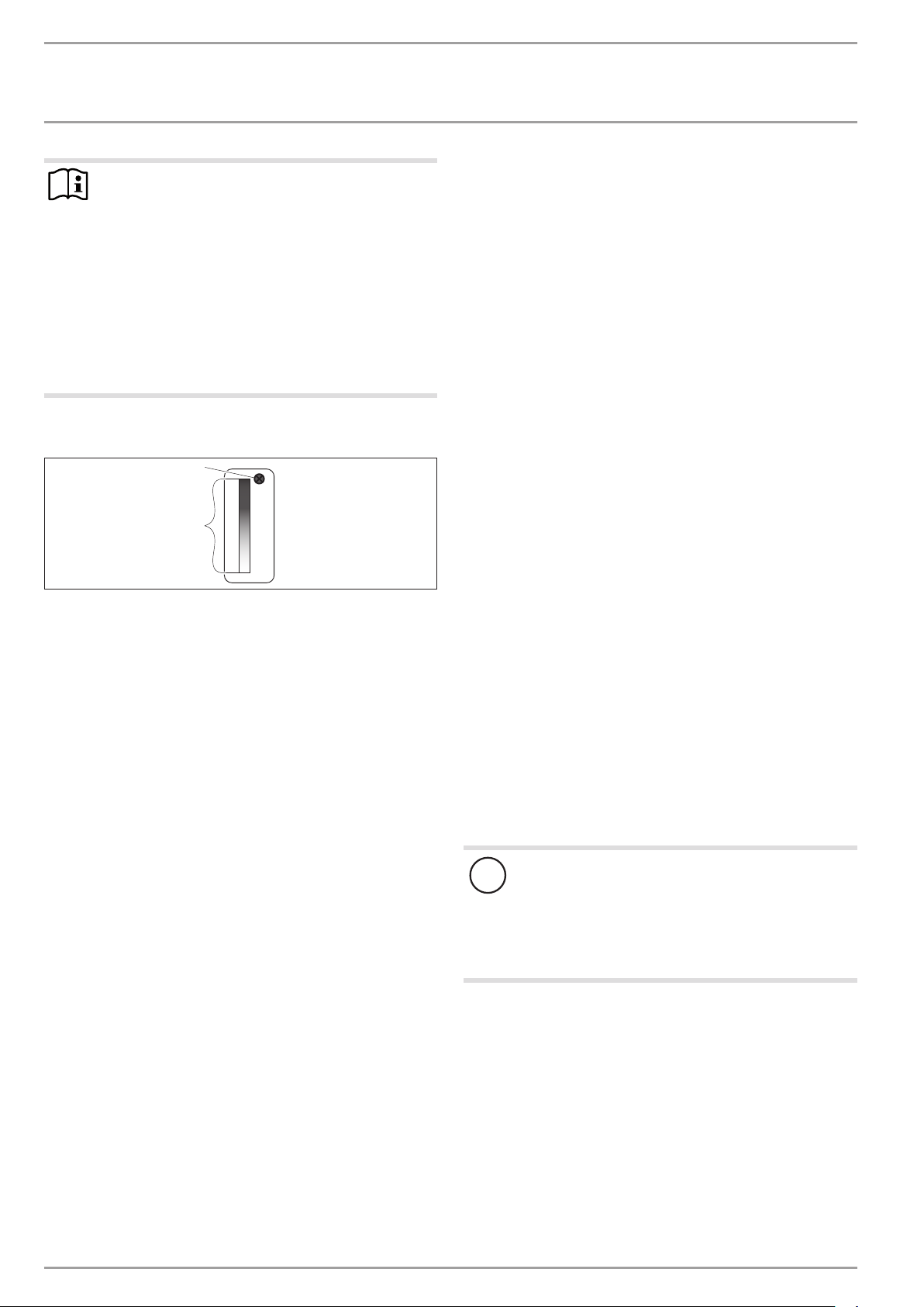
3.2 DHW heating
2
1 Cylinder top sensor
2 Integral sensor
The appliance is equipped with two temperature sensors.
- The cylinder top sensor captures the water temperature in
the upper section of the cylinder.
- The integral sensor is a temperature sensor affixed over the
entire cylinder height. The integral sensor determines the
average cylinder temperature.
The appliance display indicates the temperature in the upper section of the cylinder, which is captured by the cylinder top sensor.
The appliance control unit uses the average cylinder temperature
captured by the integral sensor.
DHW heating is started when the average cylinder temperature
has fallen and the cylinder holds only 40% of the thermal energy
it held when it was heated fully to the set temperature.
The temperature captured by the sensor at the cylinder top may
still correspond to the set temperature.
For information on the heat-up time, see chapter "Specification".
The calculation of the available amount of mixed water is based
on the average cylinder temperature. The amount of mixed water
is only calculated if the water temperature in the upper section of
the cylinder is higher than 40 °C.
DHW is normally heated by the heat pump of the appliance within
the application limits (see chapter "Specification/ Data table").
Electric emergency/booster heater
Heat pump operation will be interrupted if the application limits are exceeded or undershot in heat pump mode. The electric
emergency/booster heater takes over DHW heating to the selected
set temperature. Once the appliance is back within the application
limits, the electric emergency/booster heater switches off and
DHW heating continues with the heat pump.
In the event of an appliance fault, the electric emergency/booster
heater can be activated in emergency mode if the symbol “service/fault” is flashing. See chapter "Operation/'Rapid heat-up' key/
Emergency heating mode".
In the event of a higher hot water demand on a single occasion,
use the rapid heat-up key to activate the emergency/booster heater manually for one-off heat-up in addition to the heat pump. See
chapter "Operation/'Rapid heat-up' key/Rapid/comfort heating".
Set temperature adjustment subject to air temperature
If the temperature of the intake air is low, the maximum hot gas
temperature may be reached. In this case the appliance reduces
the set temperature on a temporary basis. Whilst the appliance
is operating at a reduced set temperature, the symbol for set
temperature adjustment is shown in the display.
Runtime-dependent rapid heat-up
The appliance offers runtime-dependent rapid heat-up for improved comfort. When this function is enabled, and the adjusted
set temperature is not reached by the heat pump after a user-defined period, the appliance switches on the electric emergency/
booster heater in parallel. As a factory default, this function is
disabled.
D0000050335
When the air intake temperature drops, the heat pump's heating
output is reduced and the heat-up time is extended. In the case
of installation with outdoor air intake, we recommend enabling
"runtime-dependent rapid heat-up" during the winter months and
as required in spring/autumn when outside temperatures are low.
Note that DHW heating with the electric emergency/booster heater
uses more power than just using the heat pump.
To prevent excessive power consumption, disable the function in
summer and in spring/autumn if at all possible. When the function
is activated, we recommend only reducing the factory preset of 8
hours if absolutely necessary for the same reason.
WWK301electronicSOL: Connection of an external heat
generator
Material losses
!
Even if an external heat generator is connected, do not
disconnect the appliance from the power supply as otherwise it is not protected against frost and corrosion. The
power supply must not be interrupted even in winter,
when it is possible that DHW heating is only being provided via the external heat generator.
The appliance is equipped with an integral smooth tube heat exchanger to which an external heat generator can be connected
(e.g. a solar thermal system or central heating system). The DHW
cylinder has sensor wells available for this in various positions.
Once during commissioning, the qualified contractor must match
the controls between the appliance and the external heat generator.
6 | WWK 221-301 electronic www.stiebel-eltron.com
OPERATION
Appliance description
3.3 Appliance operation outside the application
limits
To guarantee fault-free operation of the appliance, make sure
you operate the appliance within its application limits (see
chapter "Specification/ Data table").
3.3.1 Application limits for heat pump operation
Air intake temperature lower than the application limit
If the air intake temperature falls below the lower application
limit, the appliance blocks the compressor. The compressor symbol flashes. This means the compressor receives a DHW demand,
but the compressor is blocked by the control unit. Heating operation is now only possible with the electric /emergency booster
heater.
After one hour, the appliance starts the fan for two minutes and
checks whether the conditions for restarting the compressor have
been fulfilled. If the air temperature is higher by the hysteresis
value than the lower application limit, the compressor is released
for operation.
The electric emergency/booster heater remains operational until
the set DHW temperature is reached or until the lower application
limit is exceeded by the hysteresis value (approx. 1 K).
Air intake temperature higher than the application limit
If the air intake temperature exceeds the higher application limit,
the appliance blocks the compressor. Heating operation is now
only possible with the electric /emergency booster heater. After
one hour, the appliance starts the fan for two minutes and checks
whether the conditions for restarting the compressor have been
fulfilled. If the air temperature is lower by the hysteresis value
than the higher application limit, the compressor is released for
operation.
The electric emergency/booster heater remains operational until
the set DHW temperature is reached or until the temperature falls
below the higher application limit by the hysteresis value (approx.1 K).
3.4 Defrosting
Low air intake temperatures may result in the formation of hoar
frost on the evaporator, subject to relative humidity and DHW
temperature. The appliance is equipped with an electronic defrost monitor. DHW heating is interrupted during the defrosting
process. The appliance switches off the fan during the defrosting
process. The compressor continues to run. The defrosting process
is shown on the appliance display.
A maximum defrost time is stored in the appliance. If the maximum defrost time is exceeded, the appliance stops the defrosting
process and releases the electric emergency/booster heater.
3.5 Frost protection
The appliance activates the frost protection function if the integral
sensor in the DHW cylinder captures a temperature below 10°C.
The appliance then heats the water by means of the heat pump
and the electric emergency/booster heater. The heat pump and
electric emergency/booster heater switch off when the temperature captured by the integral sensor reaches 18°C.
3.6 Minimum runtime and minimum pause time
Material losses
!
When operating with external switching devices that can
interrupt the power supply to the appliance, such as time
switches, energy management systems or home automation systems, observe the following conditions:
- The minimum ON time is 60 minutes.
- The minimum pause time following a shutdown is
20 minutes.
- The appliance should not be switched on/off more
than 10 times per day.
- The breaking capacity of the switching actuator
must meet the protection requirements (see chapter
"Specification / Data table").
3.7 Connection of an external signal transmitter
Note
This type of connection must only be carried out by a
qualified electrician.
External signal transmitters can be integrated via the built-in contact input, e.g. a PV system to make use of solar power generated
on site.
The appliance has a second set temperature preselected at the
factory. This is activated in the event of an external switching
signal. Set temperature2 is higher ranking than the standard set
temperature while there is an external switching signal. Following
a one-off activation (signal is present for at least 1 minute), set
temperature2 applies for at least 20minutes and is ranked higher
than set temperature1.
You can change set temperature 2 on the appliance (see chapter
"Settings/Settings/Set temperature 2").
ENGLISH
Note
Heat-up times are longer while the evaporator is defrosting.
Note
The appliance starts the defrosting process as soon as
the compressor runtime reaches the "Defrost required"
time span stored in the appliance.
www.stiebel-eltron.com WWK 221-301 electronic | 7
OPERATION
Settings
4. Settings
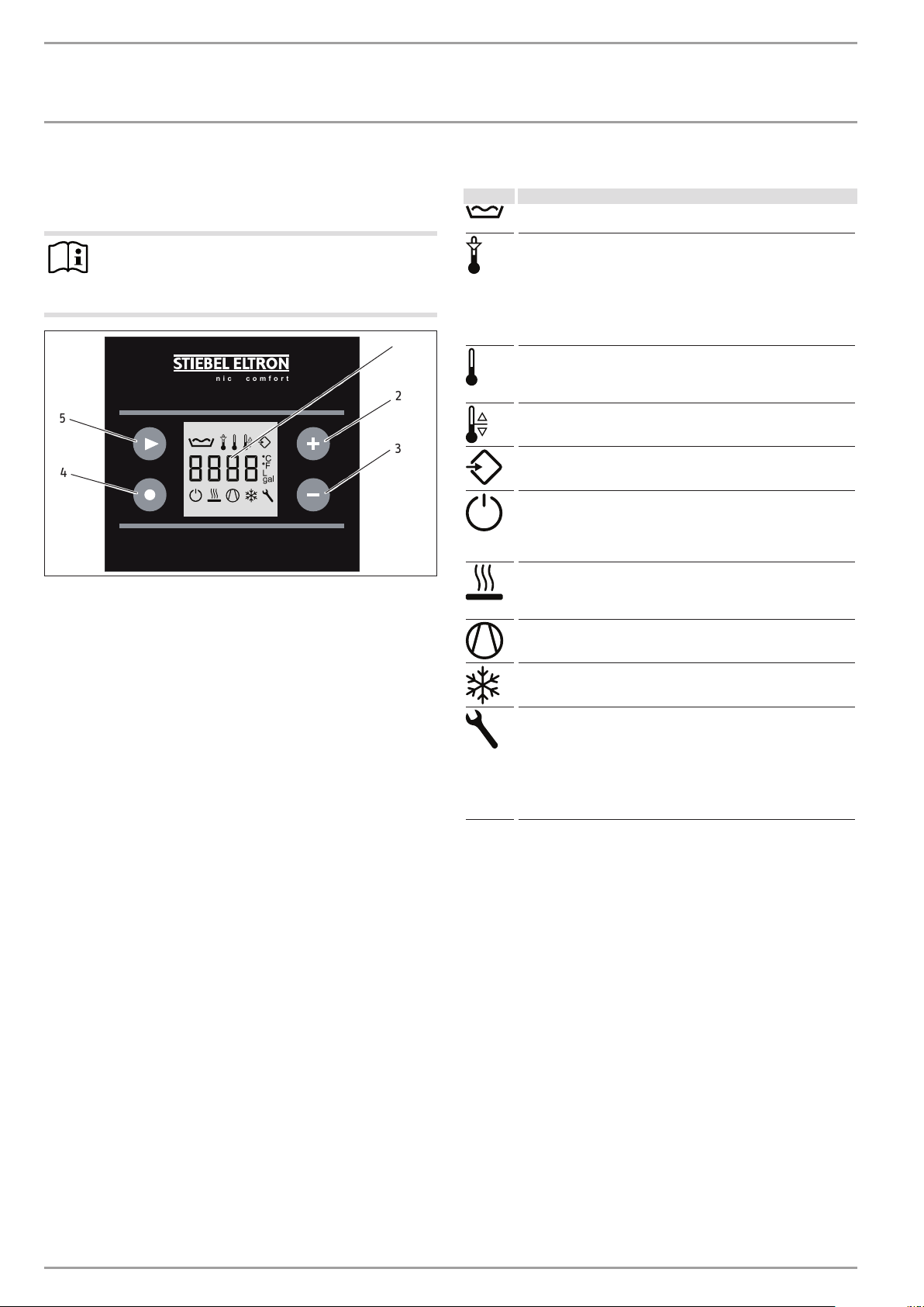
4.1 Display and controls
Note
15seconds after every operation, the appliance automatically reverts to the default display (amount of mixed
water) and saves the set value.
electronic comfort
5
4
1 "Mixed water volume" display (l|40°C)/
"Actual temperature upper cylinder section" display/
"Set temperature1" display/
“Set temperature2” display/
"Fault code" display
2 "Plus" key
3 "Minus" key
4 "Quick heat-up" key
5 "Menu" key
4.1.1 Symbols
Symbol Description
Mixed water volume: The currently available amount of mixed
1
2
3
D0000059162
water at 40°C and at 15°C cold water temperature is shown.
Set temperature adjustment: Subject to intake temperature and
hot gas temperature, the appliance may temporarily reduce the set
temperature to the actual value captured by the integral sensor.
The appliance displays the "set temperature adjustment" symbol
and blocks DHW heating until the actual temperature captured by
the integral sensor is 6K below the temporary set temperature.
DHW heating is then re-enabled and the originally selected set
temperature is again applied.
Actual temperature: The current actual temperature is shown. The
actual temperature indicates the temperature in the upper section
of the DHW cylinder and therefore largely corresponds to the outlet
temperature.
Set temperature
External signal transmitter: Set temperature2 is the DHW temperature to which the appliance regulates if an external signal transmitter is connected and active.
Standby: The symbol flashes, if the appliance PCB and load (compressor) are separately supplied with voltage. This connection
option is required, if the appliance is to be operated via switchable
sockets in an energy management system (see "Electrical connection" chapter) for example.
electric emergency/booster heater: This symbol indicates the presence of a demand on this component. This symbol being displayed
does not necessarily mean that the electric emergency/booster
heater is in operation.
Heat pump: This symbol indicates the presence of a demand on
this component. This symbol being displayed does not necessarily
mean that the compressor is running.
Defrost active
Service/fault: If the "service/fault" symbol appears on the display,
inform your qualified contractor. Continuous illumination of the
symbol indicates that the fault is not preventing appliance operation. A flashing "Service/fault" symbol indicates that water is
not being heated and that it is essential you notify your qualified
contractor. Switching the appliance to emergency mode is a special
case. The electric emergency/booster heater will then heat the
water despite the flashing "Service/fault" symbol.
The symbols for electric emergency/booster heater and heat pump
are displayed when there is a demand for these appliance components. These symbols being displayed does not necessarily mean
that the electric emergency/booster heater and the heat pump
are running.
Example: The appliance is in rapid/comfort heat-up mode. The
electric emergency/booster heater switches off when the temperature in the upper cylinder section has reached 65°C. The heat
pump has not yet heated the lower section to 65°C and the rapid/
comfort heat-up function has therefore not been terminated yet.
The "electric emergency/booster heater" symbol is displayed until
the rapid/comfort heating has terminated.
8 | WWK 221-301 electronic www.stiebel-eltron.com
OPERATION
Settings
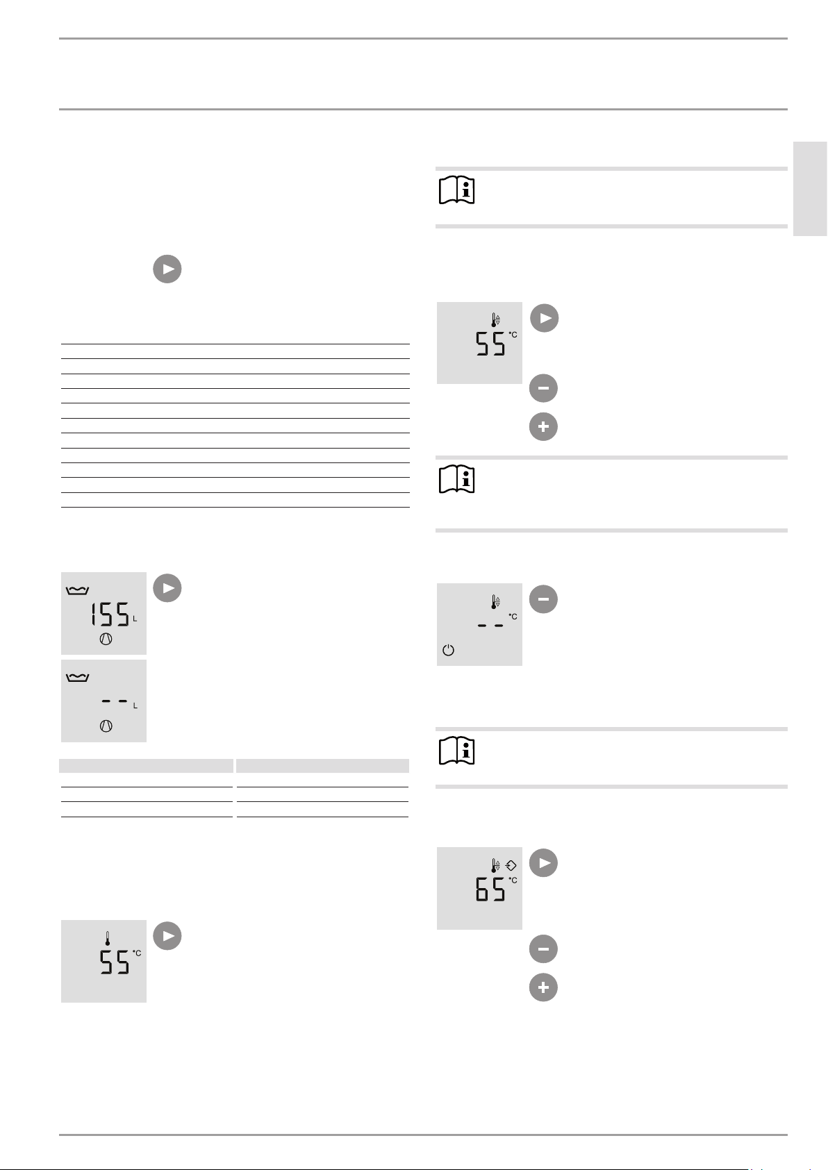
4.2 Settings
Menu
In default display mode, the display shows the amount of mixed
water.
The "Menu" key allows you to call up all
information and adjustment options in
sequence. The relevant symbol appears.
Menu
"Mixed water volume" display
"Actual temperature" display
Set temperature 1
Set temperature 2
Fan speed
"Air intake temperature" display
Enabilng the "runtime-dependent rapid heat-up" function
Time input for the "runtime-dependent rapid heat-up" function
Changing units
Fault code
E fault code
"Mixed water volume" display
The currently available amount of mixed
water at 40°C and at 15°C cold water
temperature is shown.
Set temperature 1
Note
For hygiene reasons, never set the DHW temperature
below 50°C.
Set temperature1 is the DHW temperature to which the appliance
regulates if no external signal transmitter is connected and active.
Set temperature1 is factory-set to 55°C.
In the "Actual temperature" menu, press
"Menu" once to access the "Set temperature 1" menu.
The "set temperature1" symbol appears.
Adjust set temperature1 from 20°C to
65°C using the “Plus” and “Minus” keys.
Note
Another way to adjust set temperature1 is to press the
"Plus" or "Minus" keys from within the default display
(mixed water volume).
Frost protection
Only frost protection remains active if
you set the set temperature to below
20°C using the "Minus" key. The display
shows "--°C".
ENGLISH
DHW demand for Mixed water volume at 40°C
Bath 120-150 l
Shower 30-50 l
Washing hands 2-5 l
The amount of mixed water that can be achieved depends on the
cylinder capacity and the set temperature selected.
"Actual temperature" display
"--L" is shown if less than 10l mixed
water is available.
In the "Mixed water volume" menu, press
"Menu" once to access the "Actual temperature" menu.
The "Actual temperature" symbol appears.
The current actual temperature is shown.
The actual temperature indicates the
temperature in the upper section of the
DHW cylinder and largely corresponds to
the outlet temperature.
Set temperature 2
Note
For hygiene reasons, never set the DHW temperature
below 50°C.
Set temperature2 is the DHW temperature to which the appliance
regulates if an external signal transmitter is connected and active.
In the "Set temperature1" menu, press
"Menu" once to access the "Set temperature2" menu.
The "External signal transmitter" symbol
appears.
Adjust set temperature2 from 20°C to
65°C using "Plus" and "Minus".
www.stiebel-eltron.com WWK 221-301 electronic | 9
OPERATION
A
0 5 10 15 20 25 30 35 40 45 50 55 60 65 70 75 t [min]
Settings
Operation with external signal transmitter
Material losses
!
See "Permissible voltage range for external signal transmitters" in the "Specification/data table" chapter.
As standard, the appliances feature the ability to assign a specific, individual set DHW temperature ("set temperature2") to a
connected external signal transmitter, such as a PV system or a
low tariff transmitter.
This set temperature 2 is activated if the terminal connected to
the external signal transmitter receives a signal (see "Electrical
connection/external signal transmitter connection option" chapter). While activated, set temperature2 replaces the standard set
DHW temperature (set temperature1).
If set temperature2 is activated by the external signal transmitter,
this set temperature will then be active for at least 20minutes.
If the external signal remains active after these 20minutes have
passed, the compressor will run until the external signal drops
out. If not, the selected set temperature1 is re-enabled.
When the relevant DHW set temperature has been reached, the
compressor switches off and remains off for a minimum idle time
of 20minutes.
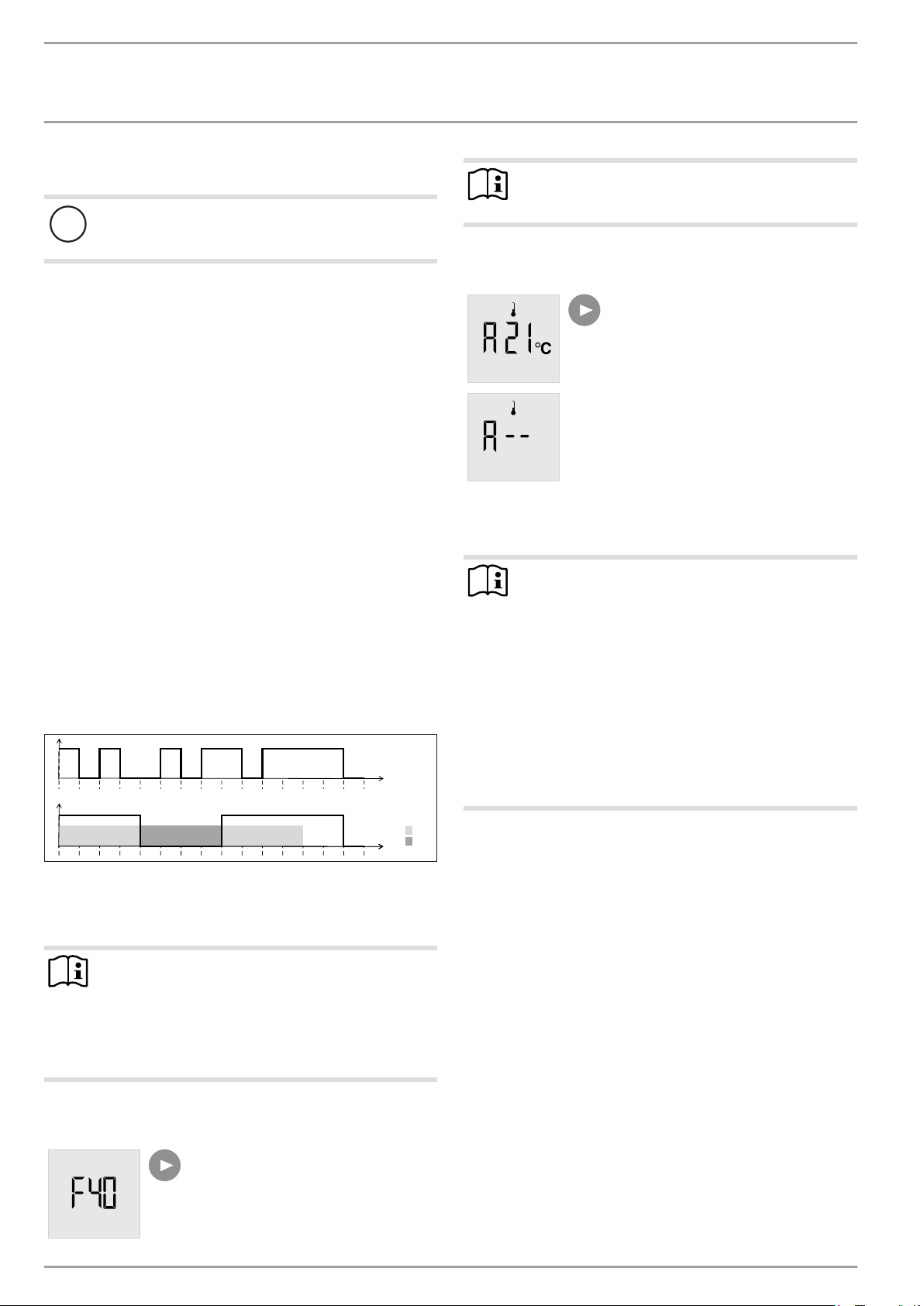
The following diagram illustrates the connections by means of a
sample signal sequence from an external signal transmitter.
Example:
- Water temperature = 55°C
- Set temperature 1 = 50°C
- Set temperature 2 = 65°C
1
0
0 5 10 15 20 25 30 35 40 45 50 55 60 65 70 75 t [min]
B
1
0 2
A External signal
B Compressor
1 20 min. minimum runtime, set temperature2
2 20 min. minimum compressor idle time
Note
An external signal must be present for at least 60seconds before the control unit responds to it. This will for
example prevent a brief burst of sunshine from triggering
a heat-up process, which due to a lack of further insolation can then not be supplied with PV power generated
on site.
Fan speed
The current set fan output appears, identified by a preceding F.
Note
Do not change the fan output. Your qualified contractor
has set this value during commissioning.
Air intake temperature display
An "A" appears as the intake temperature
symbol.
The current air intake temperature is
displayed.
The air intake temperature is only displayed while the appliance fan is running. If it is not possible to establish an
air intake temperature, two dashes are
shown.
Enabilng the "runtime-dependent rapid heat-up" function
Note
Only use runtime-dependent rapid heat-up when required, and only at low intake temperatures, e.g. with
outdoor air operation in winter and in spring/autumn if
appropriate. Avoid using runtime-dependent rapid heatup at intake temperatures for which heating without the
electric emergency/booster heater normally covers the
prevailing demand. In such cases, selecting too short a
runtime leads to unnecessary electricity bills. The factory-preset runtime is 8hours and should not be less than
this with the function activated continuously.
To prevent excessive power consumption, disable the
function in summer and in spring/autumn if at all possible.
1
For improved comfort, the appliance offers runtime-dependent
D0000034613
rapid heat-up. If the selected set temperature is not reached by the
heat pump after a user-defined period, the appliance switches on
the electric emergency/booster heater in parallel to back up the
heat pump (subject to this function being enabled). Once the set
value has been reached, the electric emergency/booster heater
remains inactive until the set time has elapsed again following a
heat demand. As a factory default, this function is disabled.
In the case of installation with outdoor air intake, we recommend
enabling "runtime-dependent rapid heat-up" during the winter
months and as required in spring/autumn when outside temperatures are low. This prevents any loss of comfort if, say, the heat
pump output falls as a result of the outside temperature dropping
when taking in outdoor air, and the heat-up time is thus extended.
The period after which the electric emergency/booster heater
provides automatic back-up needs to be selected individually by
the user based on local conditions. DHW consumption and the
expected intake temperatures need to be considered.
This function is set in two stages. First enable the function and set
the runtime in the second parameter.
10 | WWK 221-301 electronic www.stiebel-eltron.com
OPERATION
Settings
The tHE0 setting disables the "runtime-dependent rapid heat-up" function.
This function is enabled via setting tHE1.
The function is disabled at the factory.
Switch between the tHE0 and tHE1 set-
tings using the "Plus" and "Minus" keys.
The tHE1 setting allows the electric
emergency/booster heater to cut in if
the set temperature is not reached after
expiry of the runtime selected below.
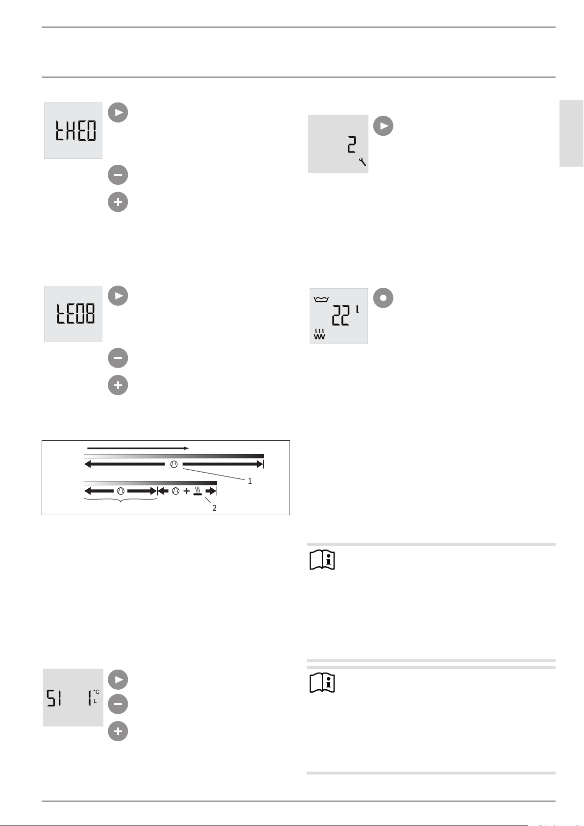
Time input for the "runtime-dependent rapid heat-up"
function
Set the runtime using the "Plus" and
"Minus" keys. After the set number of
hours, the appliance checks whether the
set temperature has been reached. If this
is not the case, the appliance switches on
the electric emergency/booster heater.
The factory default is 8hours.
t
thE0
thE1
tE08
1 Heat pump symbol
2 Electric emergency/booster heater symbol
tHE0 Runtime-dependent rapid heat-up disabled
tHE1 Runtime-dependent rapid heat-up enabled
tE08 Adjustable number of hours (e.g. 8 in this case) during
which heating is only provided by the heat pump
Changing units
You can select whether the temperatures and the volume details
are displayed in SI units or US units. If you select 1, the values are
displayed in degrees Celsius and litres. If you select 0, the values
are displayed in degrees Fahrenheit and gallons.
2
1
Fault code
If the "Service/fault" symbol illuminates
or flashes, you can query the fault code
using the "Menu" key. This menu remains
disabled if no fault has arisen.
See chapter "Troubleshooting/ Fault codes".
E fault code
A fault code preceded by E appears if the fault relates to the refrigerant circuit. Notify a qualified contractor.
4.3 "Quick heat-up" key
4.3.1 Quick/comfort heat-up
Normally, the "Rapid heat-up" key is used to enable rapid/comfort
heating, which enables you to cover unexpectedly high DHW demands without changing any of the appliance's standard settings.
If quick/comfort heat-up is activated manually by pressing the
relevant key, the heat pump and the electric emergency/booster heater will start in parallel, irrespective of the selected set
temperature, and will remain active until the DHW temperature
in the cylinder has reached 65°C. To save energy, the electric
emergency/booster heater switches off early, as soon as a temperature of 65°C has been achieved in the upper cylinder section
(quick heat-up). The rapid/comfort heating function remains active
D0000052266
until a temperature of 65°C has been achieved throughout the
DHW cylinder (comfort heating). The appliance then automatically
switches back to the previously set parameters.
Note
The "electric emergency/booster heater" and "heat pump"
symbols are displayed until the rapid/comfort heating
terminates.
During rapid/comfort heating, the "electric emergency/
booster heater" symbol is displayed until the heat pump
has heated the entire cylinder content to 65°C and the
function terminates. The electric emergency/booster
heater already switches off when the 65°C has been
achieved in the upper cylinder section.
Press the "Quick heat-up" key.
The "heat pump" and "electric emergency/booster heater" symbols appear.
ENGLISH
Press the "Menu" key until "SI" appears
in the display.
Using the "Plus" and "Minus" keys, set
whether the display should use SI units
(1) or US units (0).
www.stiebel-eltron.com WWK 221-301 electronic | 11
Note
If the quick/comfort heat-up has been activated unintentionally, you can cancel the function by lowering the
set temperature.
Hold down the "Minus" key, until you hear a clicking
noise caused by the heat pump and emergency/
booster heater switching off. At the same time, the
set temperature also reverts to the value that was
selected before quick/comfort heat-up was enabled.
 Loading...