

STIEBEL ELTRON WWK 220 electronic, WWK 300 electronic, WWK 300 electronic SOL Operation And Installation
OPERATION AND INSTALLATION
OBSŁUGA I INSTALACJA
DHW heat pump | Pompa ciepła do pogrzewania wody użytkowej
» WWK 220 electronic
» WWK 300 electronic
» WWK 300 electronic SOL

CONTENTS
SPECIAL INFORMATION
OPERATION
1. General information �����������������������������������������4
1.1 Safety instructions ����������������������������������������������� 4
1.2 Other symbols in this documentation ����������������������� 4
1.3 Units of measurement ������������������������������������������ 4
1.4 Standardised output data �������������������������������������� 4
2. Safety ���������������������������������������������������������� 4
2.1 Intended use ������������������������������������������������������ 4
2.2 Incorrect use ������������������������������������������������������ 5
2.3 General safety instructions ������������������������������������ 5
2.4 CE designation ��������������������������������������������������� 5
2.5 Test symbols ������������������������������������������������������ 5
3. Appliance description ���������������������������������������6
3.1 Heating the DHW cylinder ������������������������������������� 6
3.2 Appliance operation outside the application limits ������� 7
3.3 Frost protection �������������������������������������������������� 7
4. Settings �������������������������������������������������������7
4.1 Display and controls ��������������������������������������������� 7
4.2 Settings ������������������������������������������������������������ 8
4.3 Calling up fault codes ������������������������������������������� 9
4.4 Rapid heating key ����������������������������������������������� 9
4.5 Emergency shutdown ������������������������������������������ 10
5. Maintenance and care ������������������������������������� 10
6. Troubleshooting �������������������������������������������� 11
12. Shutdown ��������������������������������������������������� 19
13. Troubleshooting �������������������������������������������� 20
13.1 Fault table �������������������������������������������������������� 20
13.2 Resetting the safety pressure limiter ����������������������� 20
13.3 Resetting the high limit safety cut-out ��������������������� 20
13.4 Motor overload relay �������������������������������������������20
14. Maintenance and cleaning �������������������������������� 21
14.1 Removing the appliance cover ������������������������������� 21
14.2 Removing the casing ring ������������������������������������� 21
14.3 Cleaning the evaporator ��������������������������������������� 22
14.4 Draining the cylinder ������������������������������������������ 22
14.5 Descaling the electric emergency/booster heater ������� 22
14.6 Protective anode ������������������������������������������������ 22
14.7 Valves ������������������������������������������������������������� 22
14.8 Replacing the power cable ����������������������������������� 23
14.9 Fitting the casing ring �����������������������������������������23
14.10 Fitting the appliance cover ����������������������������������� 23
15. Specification ������������������������������������������������ 24
15.1 Dimensions and connections ��������������������������������� 24
15.2 Wiring diagram ������������������������������������������������� 27
15.3 Data table �������������������������������������������������������� 28
GUARANTEE
ENVIRONMENT AND RECYCLING
INSTALLATION
7. Safety �������������������������������������������������������� 13
7.1 General safety instructions ����������������������������������� 13
7.2 Instructions, standards and regulations ������������������� 13
8. Appliance description ������������������������������������� 13
8.1 Standard delivery ����������������������������������������������� 13
8.2 Required accessories ������������������������������������������13
8.3 Further accessories���������������������������������������������13
8.4 Incorrect use ����������������������������������������������������� 13
9. Preparations ������������������������������������������������ 13
9.1 Transport ��������������������������������������������������������� 13
9.2 Storage ������������������������������������������������������������ 14
9.3 Installation site �������������������������������������������������� 14
9.4 Siting the appliance �������������������������������������������� 15
10. Installation �������������������������������������������������� 16
10.1 Water connection ����������������������������������������������� 16
10.2 Connection of an external heat generator (only
WWK300electronicSOL) ������������������������������������� 16
10.3 Condensate drain ����������������������������������������������� 17
10.4 Power supply ���������������������������������������������������� 17
10.5 Assembling the appliance ������������������������������������ 18
11. Commissioning ��������������������������������������������� 19
11.1 Initial start-up ��������������������������������������������������� 19
11.2 Recommissioning ����������������������������������������������� 19
2 | WWK 220-300 electronic www.stiebel-eltron.com

SPECIAL INFORMATION
SPECIAL INFORMATION
- The appliance may be used by children aged8
and up and persons with reduced physical, sensory or mental capabilities or a lack of experience
and know-how, provided that they are supervised
or they have been instructed on how to use the
appliance safely and have understood the resulting risks. Children must never play with the appliance. Children must never clean the appliance
or perform user maintenance unless they are
supervised.
- Observe all applicable national and regional regulations and instructions during installation.
- The appliance is not approved for outdoor
installation.
- Observe the minimum clearances (see chapter "Installation/ Preparations/ Siting the
appliance").
- Drain the appliance as described in chapter "Installation/ Maintenance and cleaning/ Draining
the cylinder".
- Install a type-tested safety valve in the cold water
supply line.
- The maximum pressure in the cold water supply
line must be at least 20% below the response
pressure of the safety valve. If the maximum
pressure in the cold water supply line is higher,
install a pressure reducing valve.
- Size the drain so that water can drain off unimpeded when the safety valve is fully opened.
- Fit the discharge pipe of the safety valve with
a constant downward slope and in a room free
from the risk of frost.
- The safety valve discharge aperture must remain
open to atmosphere.
ENGLISH
- Observe the requirements concerning the installation room (see chapter "Specification/ Data
table").
- If the appliance is permanently connected to the
power supply, ensure that the appliance can be
separated from the power supply by an isolator
that disconnects omnipolar with at least 3mm
contact separation. Contactors, mains isolators or
fuses can be used for this.
- Observe the safety measures to prevent contact
with dangerous 'live' currents.
- Observe the MCB/fuse protection required for
the appliance (see chapter "Specification/ Data
table").
- The power cable must only be replaced (for example if damaged) with an original spare part by
a qualified contractor authorised by the manufacturer (connection typeX).
- The appliance is pressurised. During the heat-up
process, expansion water will drip from the safety
valve.
- Regularly activate the safety valve to prevent
it from becoming blocked, e.g. by limescale
deposits.
www.stiebel-eltron.com WWK 220-300 electronic | 3
OPERATION
General information
OPERATION
1. General information
The chapters "Special Information" and "Operation" are intended
for both the user and qualified contractors.
The chapter "Installation" is intended for qualified contractors.
Note
Read these instructions carefully before using the appliance and retain them for future reference.
Pass on the instructions to any new user where appropriate.
Symbol Meaning
!
This symbol indicates that you have to do something. The ac-
tion you need to take is described step by step.
Material losses
(appliance damage, consequential losses and environmental pollution)
Appliance disposal
1.3 Units of measurement
Note
All measurements are given in mm unless stated otherwise.
1.1 Safety instructions
1.1.1 Layout of safety instructions
KEYWORD Type of risk
!
Here, possible consequences are listed that may result
from failure to observe the safety instructions.
Steps to prevent the risk are listed.
1.1.2 Symbols, type of risk
Symbol Type of risk
!
1.1.3 Keywords
KEYWORD Meaning
DANGER Failure to observe this information will result in serious
WARNING Failure to observe this information may result in serious
CAUTION Failure to observe this information may result in non-seri-
Injury
Electrocution
Burns
(burns, scalding)
injury or death.
injury or death.
ous or minor injury.
1.2 Other symbols in this documentation
Note
General information is identified by the adjacent symbol.
Read these texts carefully.
1.4 Standardised output data
Explanations to determine and interpret the specified standardised
output data
Standard: EN 16147
The output data specifically mentioned in text, diagrams and
technical datasheets has been determined in line with the test
conditions described in the standard shown in the heading of
this chapter.
Generally, these standardised test conditions will not fully meet
the conditions found at the installation site of the system user.
Depending on the chosen test method and the extent to which
the selected method deviates from the conditions described in the
standard shown in the heading of this chapter, any deviations can
have a considerable impact. Further factors that have an influence
on the test values are the measuring equipment, the system configuration, the age of the system and the flow rates.
A confirmation of the specified output data can only be obtained
if the conditions applicable to the relevant test match those of the
standard shown in the heading of this chapter.
2. Safety
2.1 Intended use
The appliance is intended for DHW heating within the application
limits detailed in chapter "Specification/ Data table".
The appliance is intended for domestic use, i.e. it can be used
safely by untrained persons. The appliance can also be used in a
non-domestic environment, e.g. in a small business, as long as it
is used in the same way.
Any other use beyond that described shall be deemed inappropriate. Observation of these instructions and of instructions for any
accessories used is also part of the correct use of this appliance.
4 | WWK 220-300 electronic www.stiebel-eltron.com

OPERATION
Safety
2.2 Incorrect use
The following are not permitted:
- Heating liquids other than potable water
- Operating the appliance with an empty DHW cylinder
- Operating the appliance outside the application limits (see
chapter "Specification")
- Interrupting the power supply, as without power supply the
appliance is not protected against corrosion
2.3 General safety instructions
Only qualified contractors should carry out the electrical work and
installation of this appliance. Qualified contractors are responsible
for adherence to all applicable regulations.
Operate the appliance only when fully installed and with all safety
equipment fitted.
WARNING Injury
!
The appliance may be used by children aged 8 and up and
persons with reduced physical, sensory or mental capabilities or a lack of experience and know-how, provided
that they are supervised or they have been instructed on
how to use the appliance safely and have understood
the resulting risks. Children must never play with the
appliance. Children must never clean the appliance or
perform user maintenance unless they are supervised.
CAUTION Injury
!
Never place any objects on top of the appliance. If objects
are left on the appliance, noise emissions may increase
due to resulting vibrations, and the objects could fall
and cause injury.
Material losses
!
If you disconnect the appliance from the power supply, it
is no longer protected against frost or corrosion.
Do not interrupt the power supply to the appliance.
Material losses
!
Never cover the appliance. Covering the air intake or air
discharge leads to a reduced air supply. If the air supply
is restricted, the operational reliability of the appliance
cannot be guaranteed.
Material losses
!
Only operate the appliance when the DHW cylinder has
been filled.
Material losses
!
Keep the appliance installation room free from air contaminated with oil or salt and corrosive or explosive substances.
ENGLISH
WARNING Electrocution
Contact with live components presents a threat to life.
Damage to the insulation or to individual components
may result in a threat to life.
If there is damage to the insulation, disconnect the
power supply and arrange a repair.
All work on the electrical installation must be carried
out by a qualified contractor.
WARNING Burns
The water in the DHW cylinder can be heated to temperatures in excess of 60°C. There is a risk of scalding at
outlet temperatures in excess of 43 °C.
Ensure you do not come into contact with the water
when discharged.
WARNING Burns
Touching hot components can lead to burns.
When working on hot components, always wear protective working clothing and safety gloves.
The pipework connected to the DHW outlet of the appliance can reach temperatures in excess of 60°C.
WARNING BURNS
The appliance is filled with refrigerant at the factory.
In the event of refrigerant escaping due to a leak, avoid
coming into contact with the refrigerant or inhaling the
released vapours. Ventilate the rooms affected.
2.4 CE designation
The CE designation shows that the appliance meets all essential
requirements according to the:
- Electromagnetic Compatibility Directive
- Low Voltage Directive
2.5 Test symbols
See type plate on the appliance.
www.stiebel-eltron.com WWK 220-300 electronic | 5
OPERATION
1
Appliance description
3. Appliance description
The appliance is designed for indoor installation. The appliance
operates in recirculation air mode and does not require outdoor
air. The appliance extracts heat from the ambient air. This heat is
used to heat up the water in the DHW cylinder with added electric
power. The amount of electric energy and time required to heat-up
the DHW depend on the temperature of the induced air.
This heat extraction results in a drop in the ambient temperature inside the installation room by between 1°Cand3°C. The
appliance also extracts moisture from the air, which turns into
condensate. The condensate is removed from the appliance via
the condensate drain.
When a hot water draw-off point is opened, the hot DHW is pushed
out of the appliance by the inflow of cold water.
To protect against corrosion, the DHW cylinder is coated internally with special enamel and is additionally equipped with an
impressed current anode.
The electronic control unit makes energy saving adjustments easier. Subject to the power supply and your usage pattern, the water
is heated up automatically to the set temperature.
Heat pump operating principle
A closed circuit within the appliance contains refrigerant (see
"Specification/ Data table"). This refrigerant evaporates at low
temperatures.
In the evaporator, which extracts heat from the air, the refrigerant
changes from a liquid into a gaseous state. A compressor draws
in the gaseous refrigerant and compresses it. This increase in
pressure raises the refrigerant temperature.
That requires electrical energy. The energy (motor heat) is not
lost, but reaches the downstream condenser together with the
compressed refrigerant. There, the refrigerant indirectly transfers
heat to the DHW cylinder. An expansion valve then reduces the
still prevalent pressure and the cycle starts again.
Material losses
!
If you disconnect the appliance from the power supply, it
is no longer protected against frost or corrosion.
Do not interrupt the power supply to the appliance.
Note
Following an interruption of the power supply, the
compressor operation remains blocked for at least one
minute. The PCB delays electronic starting by a minute,
during which the appliance goes through its initialising
process.
If the compressor subsequently fails to start, it may be
blocked by additional safety devices (Klixon and high
pressure switch). This block should lift after 1 to 10minutes.
After the power supply has been re-established, the appliance continues to operate with the parameters that
were selected before the power supply was interrupted.
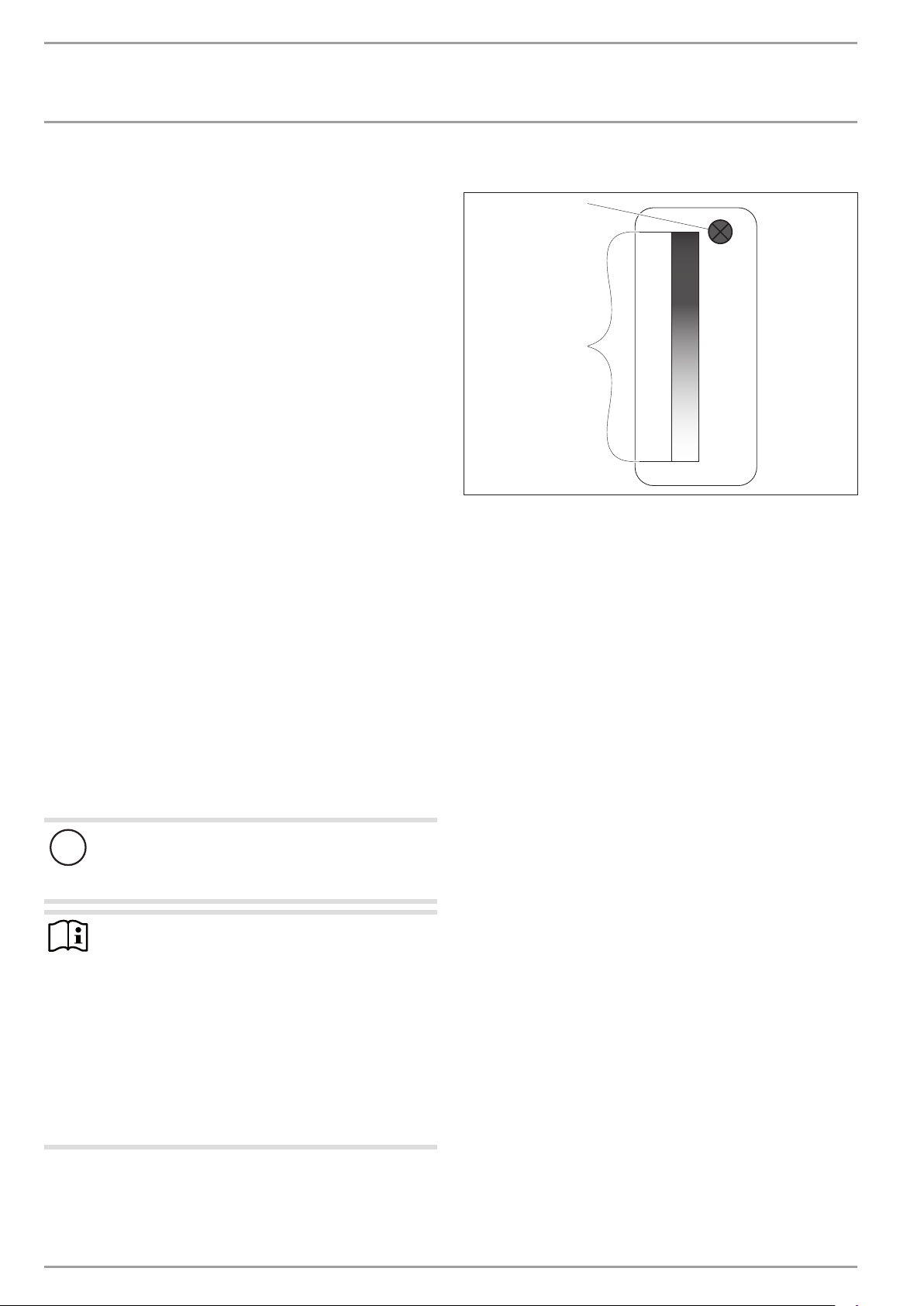
3.1 Heating the DHW cylinder
2
D0000050335
1 Domed sensor
2 Integral sensor
The appliance is equipped with two temperature sensors.
- The domed sensor captures the water temperature in the
upper section of the cylinder.
- The integral sensor is a temperature sensor affixed over the
entire cylinder height. The integral sensor determines the
average cylinder temperature.
The appliance display indicates the temperature in the upper section of the cylinder. The appliance control unit operates with the
average cylinder temperature.
The appliance may well start to heat even though the display
would indicate that it has reached the set temperature. In this
case the deviation of the average cylinder temperature from the
set value is greater than the start hysteresis.
For information on the heat-up time, see chapter "Specification".
The calculation of the available amount of mixed water is based
on the average cylinder temperature. The amount of mixed water
is only calculated if the water temperature in the upper section of
the cylinder is higher than 40 °C.
DHW is normally heated by the heat pump of the appliance within
the application limits (see chapter "Specification/ Data table").
Electric emergency/booster heater
Heat pump operation will be interrupted if the application limits are exceeded or undershot in heat pump mode. The electric
emergency/booster heater takes over the DHW heating with the
selected set temperature. Once the appliance is back within the
application limits, the electric emergency/booster heater switches
off and DHW heating continues with the heat pump.
In emergencies you can start the electric emergency/booster heater should the appliance have developed a fault and the fault code
is higher than 256. See chapter "Operation/ Rapid heating key/
Emergency heating mode".
In the event of an unexpectedly high hot water demand, the emergency/booster heater can be activated with the rapid heating key
in addition to the heat pump. See chapter "Operation/ Rapid
heating key/ Rapid/comfort heating".
6 | WWK 220-300 electronic www.stiebel-eltron.com
OPERATION
Settings
WWK300electronicSOL: Connection of an external heat
generator
Material losses
!
Even if an external heat generator is connected, do not
disconnect the appliance from the power supply as otherwise it is not protected against frost and corrosion. The
power supply must not be interrupted even in winter,
when it is possible that DHW heating is only being provided via the external heat generator.
The appliance is equipped with an integral smooth tube heat exchanger to which an external heat generator can be connected
(e.g. a solar thermal system or central heating system). The DHW
cylinder has sensor wells available for this in various positions.
Once during commissioning, the qualified contractor must match
the controls between the appliance and the external heat generator.
3.2 Appliance operation outside the application
limits
3.2.1 Ambient temperatures below the application limit
At temperatures below the lower application limit hoar frost may
form on the evaporator depending on the air humidity and water
temperature. If hoar frost forms on the evaporator, the hoar frost
temperature monitor switches the heat pump compressor off. The
compressor switches on automatically once the evaporator has
defrosted.
To guarantee fault-free operation of the appliance, make sure
you operate the appliance within its application limits (see
chapter "Specification/ Data table").
Note
Heat-up times are longer while the evaporator is defrosting.
3.2.2 Ambient temperatures above the application limit
The safety equipment switches the appliance off if the upper application limit is exceeded. Following a cooling time of several
minutes the appliance is switched back on automatically. The
appliance is switched off again if the ambient temperature rises
above the permissible temperature value again.
To guarantee fault-free operation of the appliance, make sure
you operate the appliance within its application limits (see
chapter "Specification/ Data table").
3.3 Frost protection
The appliance activates the frost protection function if the integral
sensor in the DHW cylinder captures a temperature below 10°C.
The appliance then heats the water by means of the heat pump
and the electric emergency/booster heater. The heat pump and
electric emergency/booster heater switch off when the temperature captured by the integral sensor reaches 18°C.
4. Settings
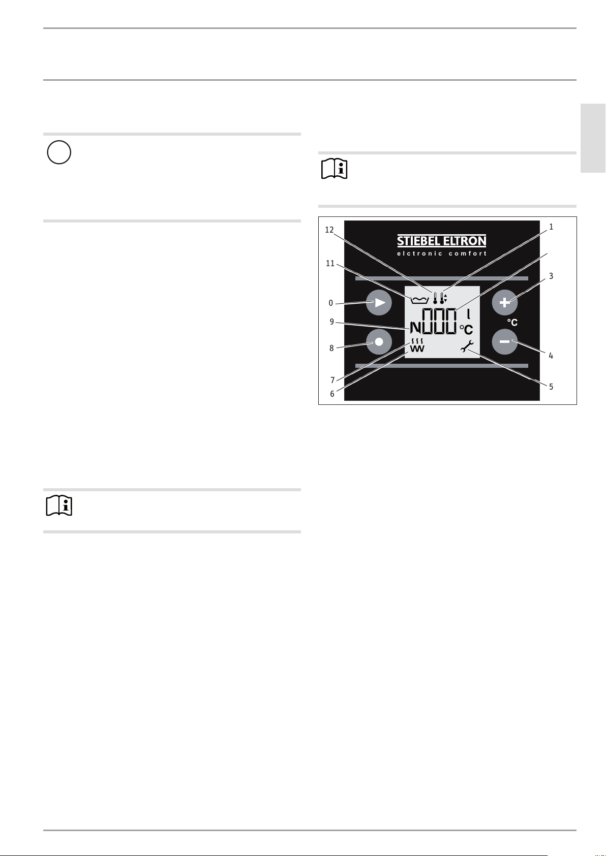
4.1 Display and controls
Note
15seconds after every adjustment, the appliance automatically reverts to the standard display (amount of
mixed water) and saves the set value.
12
elctronic comfort
11
10
9
8
7
6
1 Set temperature symbol
2 Amount of amount of mixed waterdisplay (l|40°C)/
Actual temperature display, upper cylinder section/
Set temperature1display
Display, set temperature 2 /
Fault code display
3 Plus key
4 Minus key
5 Service/fault symbol
6 Electric emergency/booster heater symbol
7 Heat pump symbol
8 Rapid heating key
9 Set temperature2 symbol
10 Menu key
11 Amount of amount of mixed watersymbol
12 Actual temperature symbol
The "electric emergency/booster heater" and "heat pump" symbols are displayed when there is a demand for these appliance
components. The display of these symbols does not necessarily
mean that the electric emergency/booster heater and the heat
pump are running.
Example: The appliance is in rapid/comfort heating mode. The
electric emergency/booster heater switches off when the temperature in the upper cylinder section has reached 65°C. The heat
pump has not yet heated the lower section to 65°C and the rapid/
comfort heating function has therefore not been terminated yet.
The electric emergency/booster heater symbol is displayed until
the rapid/comfort heating function has been terminated.
1
2
3
4
5
ENGLISH
26�03�13�0006�
www.stiebel-eltron.com WWK 220-300 electronic | 7
OPERATION
Settings
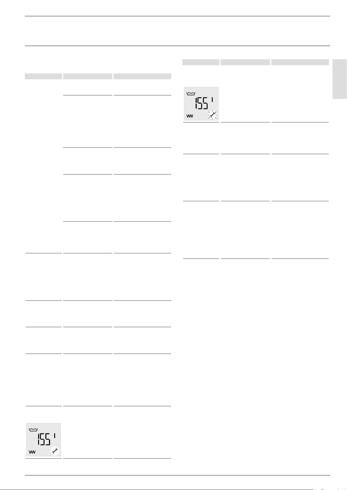
Service/fault symbol
Note
Notify your contractor if the service/fault symbol appears
on the display. Continuous illumination of the symbol
indicates that the fault is not preventing appliance operation.
A flashing service/fault symbol indicates that the water is
not being heated and that it is essential you notify your
contractor.
Switching the appliance to emergency mode is a special
case. The heat pump and the electric emergency/booster heater will then heat the water despite the flashing
service/fault symbol.
4.2 Settings
In standard display mode, the display shows amount of mixed
water.
Note
15seconds after every adjustment, the appliance automatically switches back to standard display and saves
the set value.
With the menu key, you call up all information and setting options in sequence.
The relevant symbol appears.
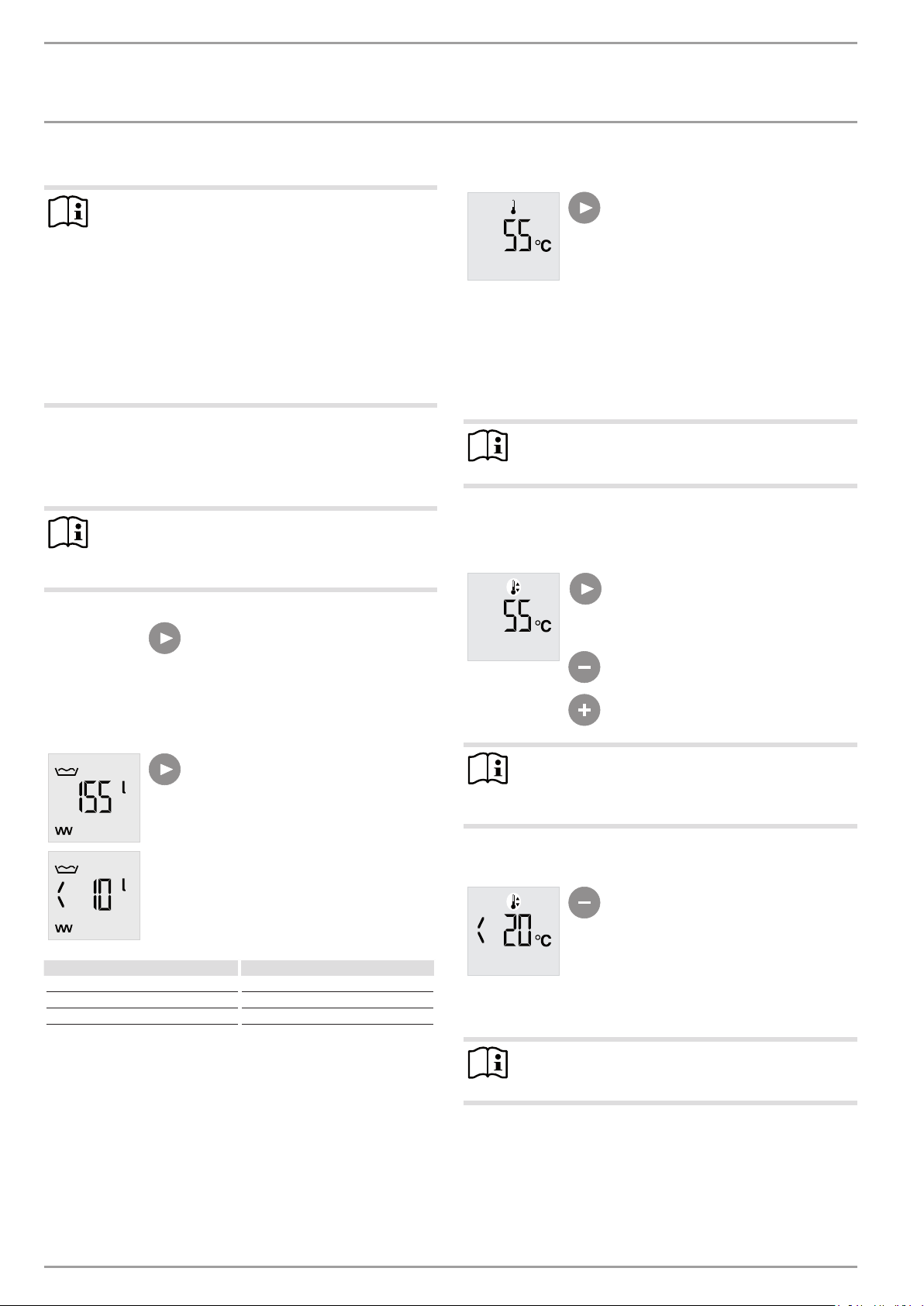
4.2.2 Actual temperature display
4.2.3 Set temperature1
Note
For reasons of hygiene, never set the DHW temperature
lower than 50°C.
The set temperature1 is the DHW temperature to which the appliance regulates if no external signal transmitter is connected and
active. Set temperature1 is set to 55°C at the factory.
In the mixed water menu, press the
menu key once to get to the actual temperature menu.
The actual temperature symbol appears.
The current actual temperature is shown.
The actual temperature indicates the
temperature in the upper section of the
DHW cylinder and therefore largely corresponds to the outlet temperature.
In the actual temperature menu, press
the menu key once to get to the menu
for set temperature1.
The set temperature1 symbol appears.
Adjust set temperature1 from 20 to 65°C
using the plus and minus keys.
4.2.1 Amount of mixed water display (standard display)
DHW demand for Mixed water volume at 40°C
Bath 120-150 l
Shower 30-50 l
Hand washing 2-5 l
The amount of mixed water that can be achieved depends on the
cylinder size and the selected set temperature.
The currently available amount of mixed
water at 40°C and at 15°C cold water
temperature is shown.
If there is currently less than 10l mixed
water available, "<10l" is shown.
Note
Another way to adjust set temperature1 is to press the
plus or minus key when in standard display (amount of
mixed water).
Frost protection
Only frost protection remains active if
you set the set temperature with the
minus key to less than 20°C.
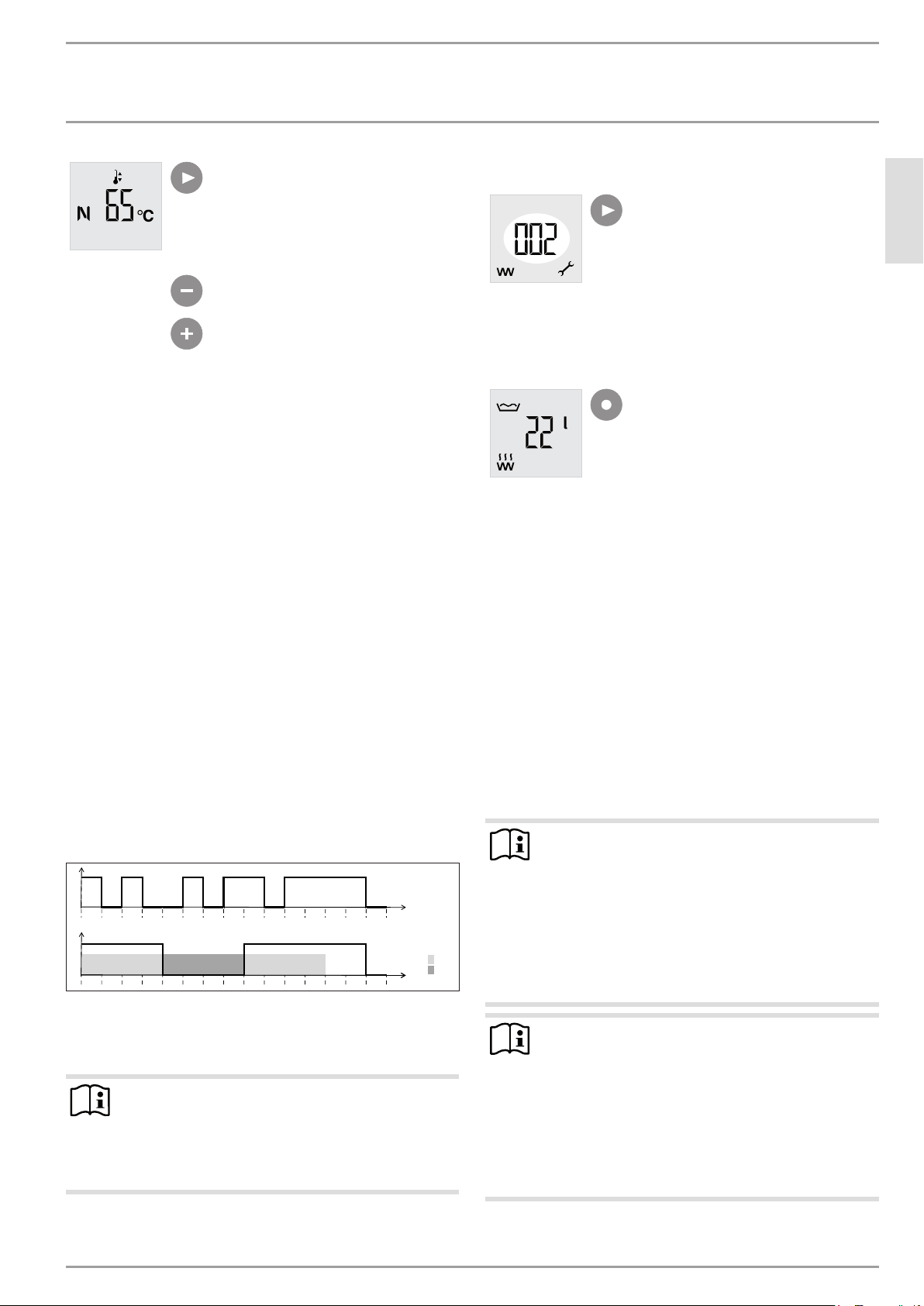
4.2.4 Solltemperatur2
Note
For reasons of hygiene, never set the DHW temperature
lower than 50°C.
Set temperature2 is the DHW temperature to which the appliance
regulates if an external signal transmitter is connected and active.
8 | WWK 220-300 electronic www.stiebel-eltron.com
OPERATION
A
0 5 10 15 20 25 30 35 40 45 50 55 60 65 70 75 t [min]
Settings
In the set temperature1 menu, press the
menu key once to get to the menu for set
temperature2.
The "set temperature2" symbol appears.
The display of set temperature2 is denoted with an "N".
Adjust set temperature2 to between 20
and 65°C using the plus and minus keys.
4.3 Calling up fault codes
In the set temperature2 menu, press the
menu key once to get to the fault code
menu. A fault code will appear if a fault
has occurred. This menu remains inactive if no fault has occurred.
See chapter "Troubleshooting/ Fault codes".
ENGLISH
4.4 Rapid heating key
Operation with external signal transmitter (230 V input)
As standard, the appliances feature the ability to allocate a specific, individual set DHW temperature (set temperature2) to a
connected external signal transmitter, such as a PV system or a
low tariff transmitter.
This set temperature2 is activated when a phase (LF signal) is
present at terminal X0/2 (see chapter "Connection types"). While
activated, set temperature2 replaces the standard set DHW temperature ("set temperature1").
If set temperature2 has been activated by the external signal
transmitter, this set temperature will then be active for at least
20minutes. If the signal remains active after those 20minutes
have passed, the compressor will run until the LF signal ends. If
not, the selected set temperature1 is activated again.
When the relevant set DHW temperature has been reached, the
compressor switches off and remains off for a minimum idle time
of 20minutes.
The following diagram illustrates the connections by means of a
sample signal sequence of an external signal transmitter.
Example:
- DHW temperature = 55°C
- Set temperature 1 = 50°C
- Set temperature 2 = 65°C
1
0
0 5 10 15 20 25 30 35 40 45 50 55 60 65 70 75 t [min]
B
1
0 2
A LF signal
B Compressor
1 20 min. minimum runtime, set temperature 2
2 20 min. minimum compressor idle time
Note
An LF signal must be active for at least 60seconds, before the control unit responds to it. This will for example
prevent a brief burst of sunshine from triggering a heatup process, which due to a lack of further insolation can
then not be supplied with PV power generated on site.
1
4.4.1 Rapid/comfort heating
Normally, the rapid heating key is used to activate the rapid/comfort heating function, which enables you to cover an unexpectedly high DHW demand without changing any of the appliance's
standard settings.
If rapid/comfort heating is activated manually by pressing the relevant key, the heat pump and the electric emergency/booster heater
will start in parallel, irrespective of the selected set temperature,
and will remain active until the DHW temperature in the cylinder
has reached 65°C. To save energy, the electric emergency/booster
heater switches off early, as soon as a temperature of 65°C has
been achieved in the upper cylinder section (rapid heating).
The rapid/comfort heating function remains active until a temperature of 65°C has been achieved in the entire DHW cylinder
(comfort heating). The appliance then automatically switches back
to the previously set parameters.
Note
The electric emergency/booster heater and heat pump
symbols are displayed until the rapid/comfort heating
function has terminated.
During rapid/comfort heating, the electric emergency/
booster heater symbol is displayed until the heat pump
has heated the entire cylinder to 65°C and the function
is terminated. The electric emergency/booster heater al-
D0000034613
ready switches off when the 65°C has been achieved in
the upper cylinder section.
Note
If the rapid/comfort heating has been activated unintentionally, you can cancel the function by lowering the set
temperature.
Hold down the minus key, until you hear a clicking
noise caused by the heat pump and emergency/
booster heater switching off. At the same time, the
set temperature also jumps back to the value that
was selected before rapid/comfort heating was activated.
Press the rapid heating key.
The heat pump and electric emergency/
booster heater symbols appear.
www.stiebel-eltron.com WWK 220-300 electronic | 9
OPERATION
Maintenance and care
4.4.2 Emergency mode
If the appliance is faulty, you can use the emergency mode to
activate the electric emergency/booster heater.
The compressor shuts down if, following a DHW demand, no temperature increase is captured for 6 hours (24 intervals of 15minutes each, during which the temperature increase is <0.25°C respectively). The fault key flashes on the display and a fault code
indicates that the appliance is not heating the water.
In such an event you can activate emergency mode by pressing the rapid heating key. After the rapid heating key has been
pressed, the indicated fault code increases by a value of 256, as
the fault codes are added together (see fault code table in chapter
"Troubleshooting"). The fault key continues to flash. The electric
emergency/booster heater is activated.
The current set temperature (set temperature1 or set temperature2) is ignored. In emergency mode, the appliance operates
with a fixed set temperature of 40°C. Following a one-off activation of the function via the rapid heating key, this function remains
active for 7days.
Following 7days of emergency operation the electric emergency/
booster heater is deactivated. The fault code shown on the display
decreases by 256.
If you press the rapid heating key again within the 7days of emergency operation, the 7-day runtime for emergency mode will start
afresh from that point.
If the 7-day runtime for emergency mode has passed, you can
restart emergency operation for a further 7days by pressing the
rapid heating key.
Pressing the rapid heating key only activates emergency mode if
a fault with fault code8 occurred previously. In standard mode
pressing the rapid heating key only triggers a one-off heating of
the DHW cylinder.
Emergency mode is no longer active after an interruption of the
power supply. The appliance tries to heat with the heat pump
again. Fault code8 is only set after 6hours. Only then can emergency mode be manually activated again via the rapid heating key.
4.5 Emergency shutdown
In the event of an emergency, carry out the following steps:
Interrupt the power supply by unplugging the appliance from
the mains or by tripping the MCB.
Shut off the cold water supply.
Immediately notify a qualified contractor, as the appliance
is not protected against corrosion while the power supply is
interrupted.
5. Maintenance and care
WARNING Electrocution
Only clean the exterior of the appliance.
Never open the appliance.
Do not insert objects through the grille into the interior
of the appliance.
Never spray the appliance with water.
Never spray water into the appliance.
WARNING Injury
!
Maintenance work, such as checking the electrical safety, must only be carried out by a qualified contractor.
Appliance components
Casing Use a damp cloth to clean the casing sections. Never
Air intake grille / air
discharge grille
DHW cylinder
Electric emergency/
booster heater
Appliance Have the safety assembly and the evaporator checked
Condensate drain Undo the condensate drain. Check that the condensate
Care and maintenance t ips
use abrasive or corrosive cleaning agents.
Clean the air intake grille and air discharge grille
every six months. Cobwebs or other kinds of contamination can restrict the air supply to the appliance.
The DHW cylinder is equipped with a maintenance-free impressed current anode to safeguard
it against corrosion. The power supply must not be
interrupted while the appliance is filled with water to
enable the impressed current anode to provide protection. Otherwise there is a risk of corrosion.
Have the electric emergency/booster heater descaled
from time to time. This will extend the service life of
the electric emergency/booster heater.
regularly by a qualified contractor.
drain is clear and remove any dirt from the condensate drain connection of the appliance.
10 | WWK 220-300 electronic www.stiebel-eltron.com
OPERATION
Troubleshooting
6. Troubleshooting
Problem Cause Remedy
No hot water is
available.
The appliance is
not heating the
DHW cylinder
although the heat
pump symbol is
illuminated.
The safety valve
of the cold water
supply line is dripping.
The condensate
drain drips.
The room temperature drops too
low.
Service/fault symbol is continuously
illuminated.
No power at the appliance.
A fuse/MCB in the fuse
box has blown/responded.
The air intake or air discharge of the appliance is
blocked.
The ambient temperature
exceeds the upper application limit (see chapter
"Specification/ Data
table"). The appliance
safety equipment has
responded and the appliance has switched off
automatically.
The ambient temperature
falls below the lower application limit (see chapter "Specification/ Data
table"). The evaporator is
currently being defrosted.
The blocking time for
compressor has not
yet elapsed. Once the
compressor has been
switched off, it will only
be switched back on
again after the 20minute
compressor blocking time
has elapsed.
These units are under
water mains pressure.
During the heat-up process, expansion water will
drip from the safety valve.
The surface temperature
of the evaporator is lower
than the dew point temperature of the ambient
air. Condensate forms.
See chapter "Fault codes".
Check that the appliance
is connected to the power
supply.
Check whether the fuses/
MCBs in your fuse box have
blown/responded. If required,
disconnect the appliance from
the power supply and replace
the fuses/reset the MCBs.
Contact your contractor if the
fuse blows again after the
appliance is connected to the
power supply.
Check the air intake grille
and air discharge grille for
contamination. Remove any
contamination (see chapter
"Maintenance and care").
Wait for the appliance to cool
down. Call a qualified contractor if the appliance does
not switch back on automatically.
Wait until the appliance
switches back on automatically.
Notify a qualified contractor if
water continues to drip when
heating is completed.
The amount of condensate
depends on the air humidity
level.
Operation of the appliance can
cause the room temperature
to fall by 1 to 3°C. If the room
temperature falls by more
than 5°C, check the room size
(see chapter "Specification/
Data table"). Increasing the
room size by opening a door
to another room will remedy
this.
Notify a qualified contractor.
Problem Cause Remedy
Service/fault symbol flashes and
the water does not
heat up.
The "heat pump"
symbol is illuminated but the
compressor is not
running. The fan is
running.
The "heat pump"
symbol is flashing.
The "electric emergency/booster
heater" symbol is
flashing.
See chapter "Fault codes".
The appliance is in defrost
mode.
There is a heat demand,
but the compressor is
blocked.
A temperature controller has switched off the
"electric emergency/
booster heater" during
quick heat-up.
It is imperative that you notify
a qualified contractor.
No action required.
No action required. The
compressor switches itself
on automatically after the
compressor blocking time
has elapsed. The compressor
blocking time lasts 20minutes
once the compressor has been
switched off. The symbol stops
flashing automatically.
No action required. The appliance continues the quick
heat-up process using the
heat pump. The symbol stops
flashing when the controller
releases the "electric emergency/booster heater". The
symbol goes out when the
temperature throughout the
DHW cylinder reaches the set
temperature of 65°C.
ENGLISH
www.stiebel-eltron.com WWK 220-300 electronic | 11

OPERATION
Troubleshooting
Fault code
If the service/fault symbol is flashing or continuously illuminated
on the display, you can call up a fault code.
Repeatedly press the menu key until the
fault code is shown following set temperature2.
Fault code appears
Fault
code
0 No fault
2
4
6
8
16
32
128
256
Service/
fault
symbol
continuously illuminated
continuously illuminated
flashes Dome sensor and integral
flashes
continuously illuminated
flashes
continuously illuminated
flashes Manually activated emergency
Fault description Remedy
Dome sensor faulty. The actual
temperature display switches
over to the integral sensor. The
appliance continues to deliver
heat. The amount of mixed
water shown is always less
than 10 litres.
Integral sensor faulty. In the
event of a faulty integral sensor, the integral sensor is set
to the dome sensor value and
amount of mixed water is calculated using this value. The
appliance continues to deliver
heat.
sensor faulty. The appliance no
longer delivers heat.
The appliance has ascertained
that the DHW cylinder has not
been heated for 13 hours, despite there being a demand.
Short circuit impressed current
anode / protective anode faulty
The appliance is operating with
an empty cylinder or the appliance is not delivering heat.
The anode current is interrupted. The appliance does not
heat up.
No communication between
controller and programming
unit. The most recently selected
set values are active.
mode (only electric emergency/
booster heater active).
You can continue to
use the appliance by
activating emergency
mode. See chapter
"Emergency mode".
Immediately notify a
qualified contractor,
as the appliance is not
protected against corrosion if the impressed
current anode is faulty.
Fill the appliance. The
fault code disappears
and the appliance
starts.
The contractor needs
to check the impressed
current anode and the
wiring.
See chapter "Appliance
description/ Emergency mo de".
Application scenarios for emergency mode
If the appliance shows fault code8, you can manually activate
emergency mode. If a different fault occurred previously, but did
not cause the appliance to switch off, the display may show a fault
code that is the result of several faults added together.
Listed below are the fault codes which will allow you to activate
emergency mode.
Fault code displayed
8 8
10 Fault code 8 + fault code 2
12 8+4
24 8+16
26 8+2+16
28 8+4+16
138 8+2+128
140 8+4+128
152 8+16+1 28
154 8+2+16+128
156 8+4+16+128
When the appliance is operating in emergency mode, the fault
code shown is increased by 256.
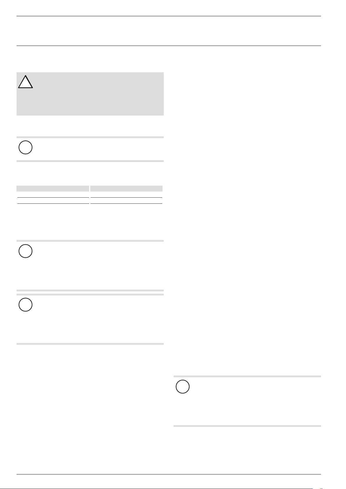
Notifying a qualified contractor
If you cannot remedy the fault, notify your qualified contractor. To
facilitate and speed up your request, provide the serial number
from the type plate (000000-0000-00000). The type plate can be
found on the left, above the "DHW outlet" connection.
Sample type plate
1
000000-0000-000000
D0000035352
1 Number on the type plate
If several faults occur, the fault codes are added up.
Example: If both the dome sensor and integral sensor are faulty,
the display shows fault code6(=2+4).
12 | WWK 220-300 electronic www.stiebel-eltron.com
INSTALLATION
Safety
INSTALLATION
7. Safety
Only a qualified contractor should carry out the installation, commissioning, maintenance and repair of the appliance.
7.1 General safety instructions
We guarantee trouble-free function and operational reliability only
if original accessories and spare parts intended for the appliance
are used.
7.2 Instructions, standards and regulations
Note
Observe all applicable national and regional regulations
and instructions.
Take note of the appliance type plate and chapter "Specification".
8. Appliance description
The heat pump drive unit is located in the upper section of the
appliance. The DHW cylinder is located in the lower section of
the appliance.
9. Preparations
9.1 Transport
CAUTION Injury
!
Take note of the weight of the appliance.
Use suitable transport aids (e.g. a sack truck) and
enough personnel for transportation.
Material losses
!
The appliance has a high centre of gravity and low overturning moment.
Safeguard the appliance against falling over.
Only set the appliance down on an even base.
Material losses
!
The appliance casing is not designed to withstand strong
forces. Incorrect handling can lead to material losses of
considerable extent.
Observe the information on the packaging.
Only remove the packaging shortly before the installation.
Do not unpack the appliance until it has arrived in the installation
room.
Leave the appliance in its packaging and on the pallet. This enables brief horizontal transport and provides places to hold onto
during transport.
ENGLISH
8.1 Standard delivery
The following are delivered with the appliance:
- Condensate drain bend
- 2 pipe connectors with plastic union nuts and gaskets for the
"cold water inlet" and "DHW outlet" connections.
8.2 Required accessories
Various safety assemblies are available that need to be selected
subject to the static pressure. These type-tested safety assemblies
protect the appliance against unacceptable excess pressure.
8.3 Further accessories
– Condensate pump (if the condensate cannot be drained off with
a naturally occurring fall)
8.4 Incorrect use
The following are not permitted:
- Operating the appliance when the casing is open
- Filling the appliance with a refrigerant other than the one
detailed in chapter "Specification/ Data table"
Observe the list of requirements regarding the installation room
and non-permissible installation sites (see chapter "Installation
site").
Vehicular transport
Material losses
!
The appliance must generally be stored and transported
vertically.
The appliance may be transported horizontally for brief periods,
over a maximum distance of 100miles and on made-up roads.
Strong shocks are not permissible.
Material losses
!
If transported horizontally, the appliance must always be
laid on the shaded side of the box.
The appliance must not remain in a horizontal position
for more than 24hours.
If the appliance was transported horizontally, leave it to
rest in a vertical position for at least one hour before
commissioning.
Observe the information on the packaging.
www.stiebel-eltron.com WWK 220-300 electronic | 13
INSTALLATION
Preparations
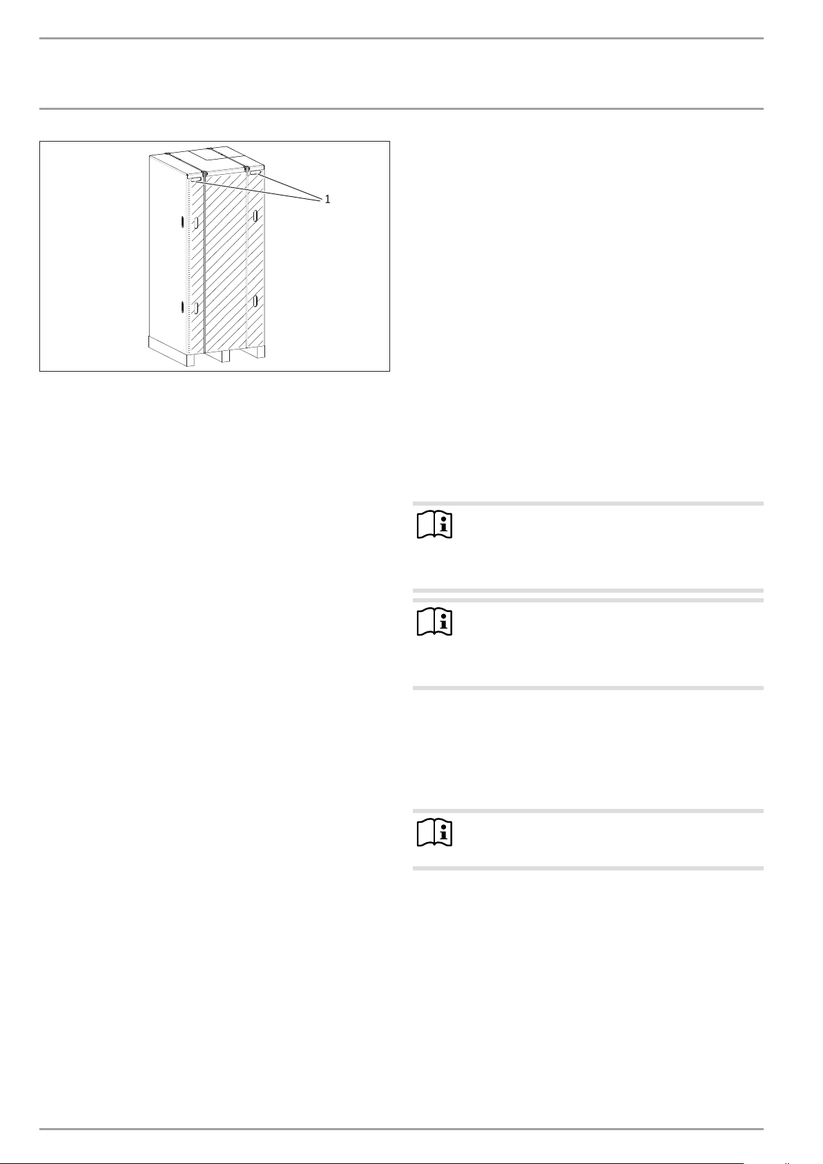
1
1 Recessed grips
Transport from vehicle to installation room
The cardboard box has reinforced recessed grips along the top.
You can use these recessed grips, as well as the pallet at the lower
end, to carry the appliance into the installation room. Take note
of the weight of the appliance and ensure a sufficient number of
personnel is available for handling the appliance.
9.2 Storage
If it is necessary to store the appliance for a prolonged period
before installation, observe the following information:
- Only store the appliance in a vertical position. Never store
the appliance horizontally.
- Store the appliance in a location that is dry and largely
dust-free.
- Protect the appliance from coming into contact with corrosive
substances.
- Ensure the appliance is not subjected to shocks or vibrations.
- Always leave sufficient space to provide access for installation, maintenance and cleaning. Observe the required
minimum clearances (see chapter "Preparations/ Siting the
appliance").
- Ensure the operation of other equipment in the installation
room is not impaired.
- To keep the duct lengths as short as possible, we recommend
installing the appliance close to the kitchen or bathroom.
- To prevent adverse effects from operating noise, never install
the appliance close to bedrooms.
The following installation sites are not permissible, due to risk of
appliance damage:
- Locations where the air is contaminated with oil or grease
D0000034797
- Saline environments
- Environments with thermal water
- Areas in proximity to high frequency machines
- Places where the air contains ammonia (e.g.sewage works)
- Places where the air contains chlorine (e.g.swimming pools)
- Generally places where the air is strongly contaminated, e.g.
due to dust, or contains aggressive substances
Note
The performance data indicated for this appliance has
been determined in line with the relevant standard, that
is at an intake temperature of 15°C. Below 15°C the
efficiency of the appliance decreases.
Note
You can improve the efficiency of the appliance by utilising the waste heat from other appliances to heat the DHW
cylinder, e.g. boilers, tumble dryers or freezers.
9.3 Installation site
The appliance is not approved for outdoor installation.
Further requirements regarding the installation room and appli-
ance positioning, to prevent appliance damage:
- The installation site must be free from flammable, highly
combustible gases and substances, as well as high levels of
dust.
- The installation room must be free from the risk of frost.
- The intake temperature of the appliance must be within the
permissible application limits (see chapter "Specification/
Data table").
- The floor of the installation room must be level and have
sufficient load bearing capacity. Take note of the weight of
the appliance with a full DHW cylinder (see "Specification/
Data table"). A floor with insufficient load bearing capacity is
in danger of collapse. If the appliance is not evenly balanced,
there may be a risk of appliance damage.
- The size of the installation room must correspond to the application limits of the appliance (see chapter "Specification/
Data table").
- Observe the safety clearances and protection zones.
Sound emissions
The sound emissions are louder on the air intake and air discharge
sides of the appliance than on the closed sides.
Never direct the air intake or air discharge towards
noise-sensitive rooms of the house, e.g. bedrooms.
Note
For details on sounds emissions, see chapter "Specification/ Data table".
14 | WWK 220-300 electronic www.stiebel-eltron.com
INSTALLATION
≥100
≥350
≥400
≥400
≥500
Preparations
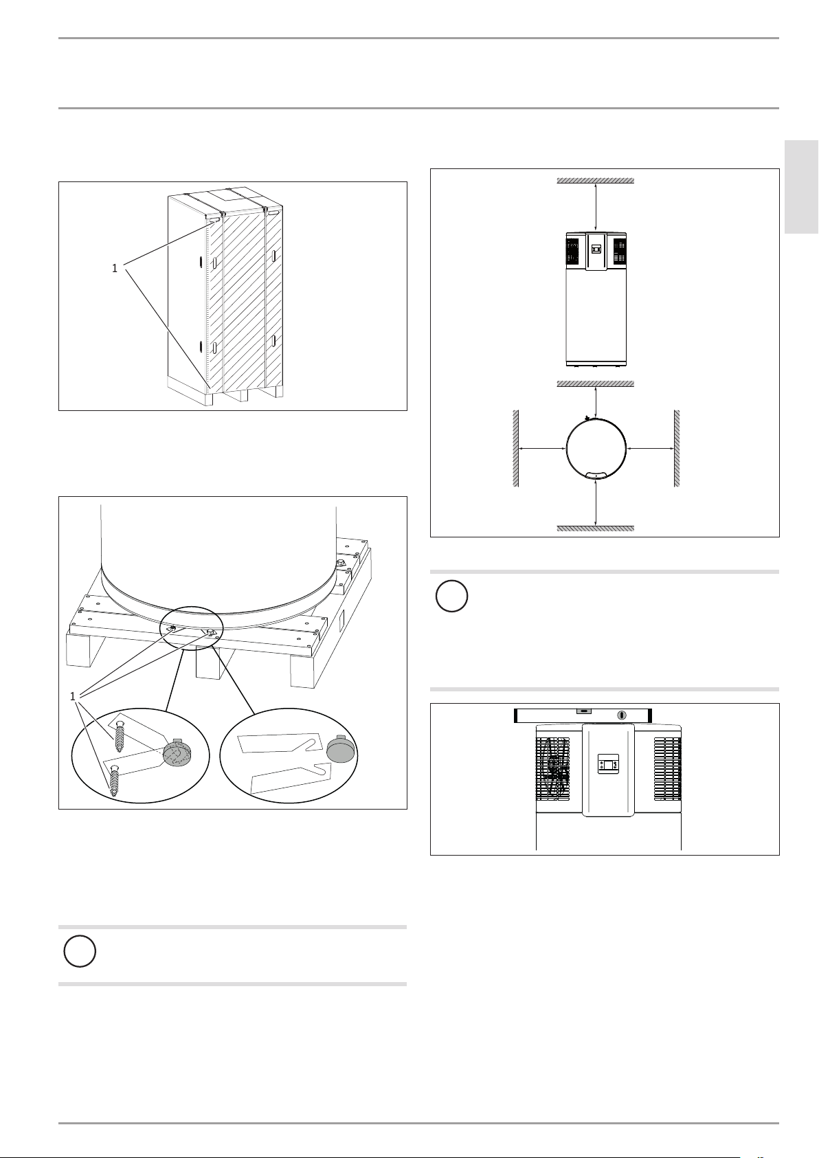
9.4 Siting the appliance
Carefully undo the cardboard packaging at the clips.
1
1 Cardboard packaging clips
The appliance is secured to the pallet with metal brackets and
screws. The metal brackets are hooked on to the feet underneath
the floor plate of the appliance.
Minimum clearances
ENGLISH
D0000034797
D0000020783
1
1.
1 Metal bracket fixing screw
Remove the fixing screws of the metal brackets from the
pallet.
Push the metal brackets a little towards the cylinder centre to
unhook them from the appliance feet.
Pull the metal brackets out from underneath the appliance.
Material losses
!
Take note of the appliance's weight and centre of gravity.
2.
Maintain the minimum clearances.
Material losses
!
The appliance must be positioned vertically to avoid
damage.
The feet under the floor plate of the appliance are
height-adjustable.
Level the appliance horizontally using the height-ad-
justable feet.
D0000034798
D0000034806
Slightly tip the appliance and carefully roll the appliance off
the pallet.
Position the appliance in the final installation site.
www.stiebel-eltron.com WWK 220-300 electronic | 15
INSTALLATION
Installation
10. Installation
WARNING Injury
!
Incorrect installation can lead to serious injury or material losses.
Before any work, ensure sufficient clearances for the
installation.
Handle sharp-edged components carefully.
10.1 Water connection
Material losses
!
Carry out all water connection and installation work in
accordance with regulations.
The following material combinations are approved for metal pipework installations:
Cold waterInlet DHW outlet
Copper pipe Copper pipe
Steel pipe Steel pipe or copper pipe
Thoroughly flush the pipework before connecting the ap-
pliance. Foreign bodies, such as welding pearls, rust, sand
or sealant can impair the operational reliability of the
appliance.
Safety valve
The appliance is a sealed unvented DHW cylinder. Provide the
appliance with a pressure relief valve.
Install a type-tested safety valve in the cold water supply
line. The response pressure of the safety valve must be below
or equal to the permissible operating pressure of the DHW
cylinder.
The safety valve protects the appliance against unacceptable excess pressure. The diameter of the cold water supply line must be
no greater than the diameter of the safety valve.
Ensure that the expansion water escaping from the safety
valve can drip into a drain, e.g. a tank or funnel.
Ensure the drain cannot be shut off.
Size the drain so that water can drain off unimpeded when
the safety valve is fully opened.
Ensure that the discharge pipe of the safety valve is open to
atmosphere.
Fit the discharge pipe of the safety valve with a constant
downward slope and in a room free from the risk of frost.
Pressure reducing valve
The maximum pressure in the cold water supply line must be at
least 20% below the response pressure of the safety valve. If the
maximum pressure in the cold water supply line is higher, install
a pressure reducing valve.
Material losses
!
To protect the connections against corrosion the water
connection must be made with flat gaskets. The use of
hemp on connections is not permissible.
The plastic union nuts included in the standard delivery
serve to prevent and insulate against cathodic scaling due
to highly conductive water.
Material losses
!
Too much torque can destroy the plastic union nuts. This
leads to a risk of appliance damage.
Never exceed a torque of 25Nm when using the gasket
supplied as standard. Keep to the permissible torque.
Using the gaskets and plastic union nuts provided, connect
the flanged copper pipes included in the standard delivery to
the "cold water inlet" and "DHW outlet" connections.
Check the gasket and plastic union nut for leaks.
Drain valve
Install a suitable drain valve at the lowest point in the cold
water inlet line.
DHW circulation
The heat losses incurred in the DHW circulation line and the electrical power consumption of the circulation pump reduce the efficiency of the system. The cooled water in the circulation line mixes
with the cylinder content. Where possible, avoid installing a DHW
circulation line. Where that is not possible, the DHW circulation
pump must be controlled thermally or by time switch.
Thermal insulation
Insulate the DHW line against heat loss in accordance with
locally applicable regulations.
10.2 Connection of an external heat generator (only
WWK300electronicSOL)
Material losses
!
Even if an external heat generator is connected, do not
disconnect the appliance from the power supply as otherwise it is not protected against frost and corrosion. The
power supply must not be interrupted even in winter,
when it is possible that DHW heating is only being provided via the external heat generator.
16 | WWK 220-300 electronic www.stiebel-eltron.com
INSTALLATION
Installation
Material losses
!
The integration of an external heat generator via the "heat
source flow" connection must not result in the application
limits being exceeded (see chapter "Specification/ Data
table").
The connected external heat generator cannot be controlled by the appliance. The external heat generator
must be controlled externally. The possibility of exceeding the maximum permissible DHW temperature in the
cylinder (as given in chapter "Specification/ Data table")
must be prevented.
Material losses
!
Carry out all installation work in accordance with regulations. In Germany, to comply with heating system regulations, an external heat generator must be connected with
a diaphragm expansion vessel and a safety valve between
the external heat generator and the DHW cylinder.
External heat generators may only be connected with DHW priority
control. As part of this, the cylinder temperature must be captured
with an electronic temperature sensor with safety low voltage.
The DHW cylinder of the appliance allows the temperature sensor
to be positioned at one of two different heights in the cylinder.
Using the sensor well in the upper third of the cylinder enables
later DHW heating through the external heat generator than the
lower sensor position.
10.4 Power supply
WARNING Electrocution
Carry out all electrical connection and installation work
in accordance with national and regional regulations.
WARNING Electrocution
If the appliance is permanently connected to the power
supply, ensure that the appliance can be separated from
the power supply by an isolator that disconnects omnipolar with at least 3mm contact separation. Contactors,
mains isolators or fuses can be used for this.
WARNING Electrocution
Observe the safety measures to prevent contact
with dangerous 'live' currents.
WARNING Electrocution
Coming into contact with 'live' components presents a
threat to life. Disconnect the appliance from the power
supply before carrying out work on the control panel.
Prevent the power supply from being switched on while
you are working on the system.
WARNING Electrocution
Insufficient earthing can lead to electrocution. Ensure
the appliance is earthed according to locally applicable
requirements.
ENGLISH
10.3 Condensate drain
Install a condensate drain hose in order to remove the condensate
which forms.
Connect the condensate drain bend included in the standard
delivery to the "condensate drain" connection.
Connect a condensate drain hose to the condensate drain
bend.
Material losses
!
Ensure condensate cannot back up.
Use a condensate drain hose with a diameter great-
er than the diameter of the condensate drain bend.
Ensure the condensate drain hose is not kinked.
Route the condensate drain hose with a continuous
fall.
The condensate drain must be open to atmosphere.
Use a suitable condensate pump if there is insufficient fall.
Observe the building characteristics.
WARNING Electrocution
The power cable must only be replaced (for example
if damaged) with an original spare part by a qualified
contractor authorised by the manufacturer (connection
typeX).
Material losses
!
The specified voltage must match the mains voltage. Observe the type plate.
Material losses
!
Never connect the appliance to the power supply before
the DHW cylinder is filled.
The appliance is delivered with a power cable with mains plug.
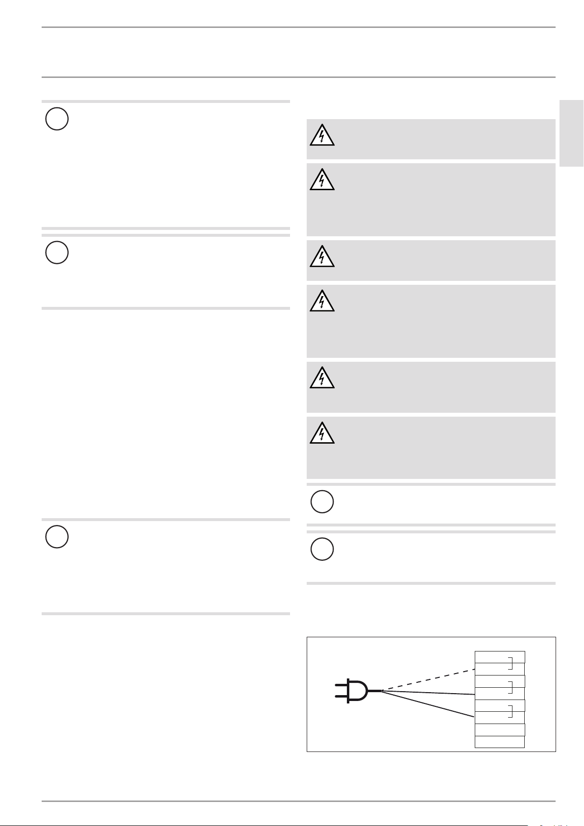
10.4.1 Standard connection without external signal transmitter
X0
PE
PE
N
N
L
L
2
1
D0000034487
www.stiebel-eltron.com WWK 220-300 electronic | 17
INSTALLATION
Installation
10.4.2 Connection with external signal transmitter
An external signal transmitter for switching a separate set DHW
temperature (set temperature2) can be connected to terminal
X0/2.
In the delivered condition, terminal X0/2 is not assigned. If this
terminal is connected to 230V, the appliance activates set temperature2.
Following a one-off activation (signal is present for at least one
minute), set temperature2 applies for at least 20minutes and is
ranked higher than set temperature1.
WARNING Electrocution
If the 230V signal of an external signal transmitter is
to be connected to terminal X0/2, do not connect the
appliance to the power supply with the factory fitted
power cable and standard plug.
Instead connect the appliance to the power supply permanently. Never interchange L1 and N.
Note
Never wire up terminal X0/1.
Example 1: Power-OFF signal with own 230V phase
X0
PE
PE
N
L1
PE
N
N
L
L
2
1
1
1 Inverter (floating contact)
The inverter power feed is located at a central distribution point
(e.g. in the main fuse box).
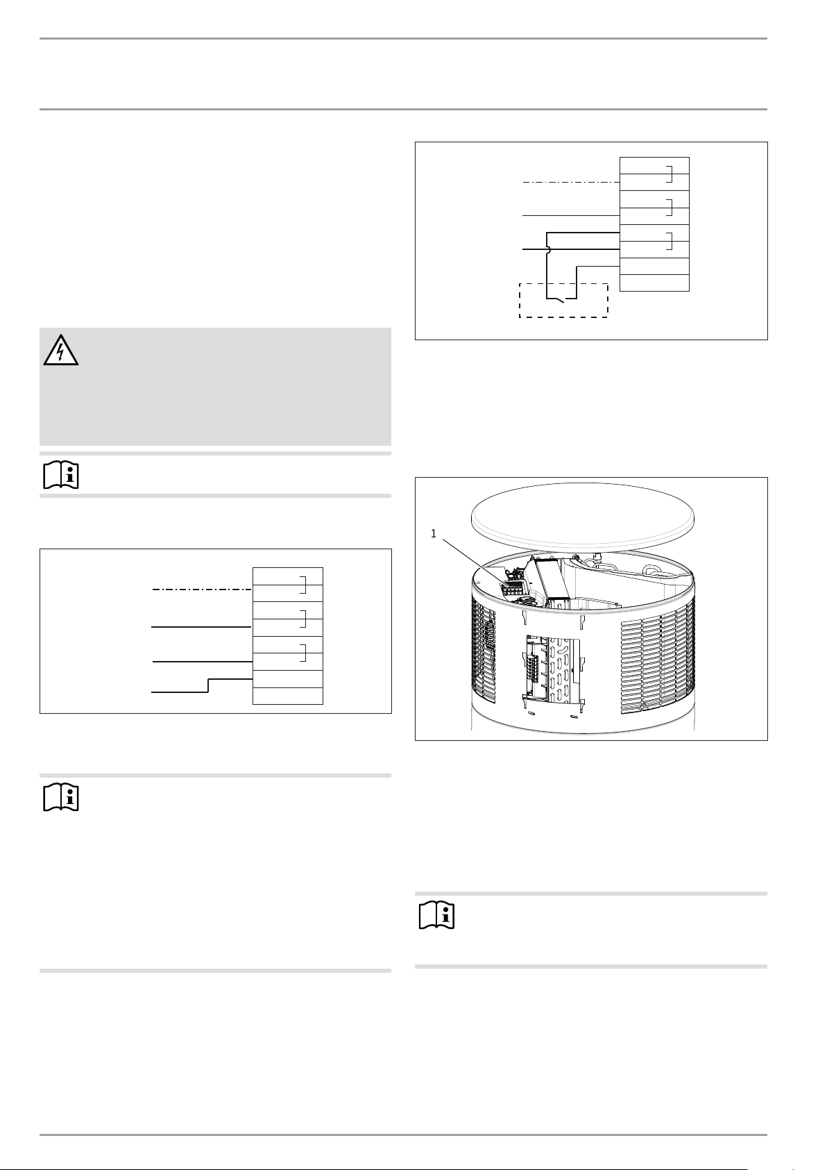
Connection to terminal block X0
Remove the appliance cover (see chapter "Cleaning and
maintenance/ Removing the appliance cover").
1
D0000034590
X0
PE
N
L1
L1, L2 oder L3
EVU:
Example 2: Photovoltaic signal via on-site relay and phase
routed outside the appliance
Note
The relay in the inverter must meet the following requirements:
- Potential-free relay (240VAC / 24VDC, 1A) with
N/O contact
- Adherence to safety regulations and standards for
safety extra low voltage
- The switching output must be programmed so that
the relay closes or opens if certain limits are exceeded or undershot (inverter output level).
If necessary, check with the inverter manufacturer whether the product meets the stated criteria.
PE
PE
N
N
L
L
2
1
D0000034589
1 Terminal X0
Prepare the leads for connection to X0 in such a manner, that
each lead terminating at X0 has a wire ferrule.
Route leads through the strain relief.
Connect the leads to X0 (see chapter "Connection with exter-
nal signal transmitter").
10.5 Assembling the appliance
Note
Refit the appliance cover after completing your work. See
chapter "Maintenance and cleaning/ Fitting the appliance
cover").
D0000034803
18 | WWK 220-300 electronic www.stiebel-eltron.com
 Loading...