

Page 1

1www.stiebel-eltron.CoM
Hot wat e r rene w a b les a i r c ondit ion i n g room He at i n g
»ISSUE 2009
TEchnIcal GUIdE
hEaT pUmpS
Page 2

Design/engineeRing anD installation
Issue March 2009
Reprinting or duplication, even partially, only with our express permission.
STIEBEL ELTRON, D-37601 Holzminden
Legal note:
In spite of the care taken in the production of this brochure, no guarantee can be given regarding the accuracy of its contents.
Information concerning equipment levels and specification are subject to modification. The equipment features described in this
brochure are not stated as agreed properties of our products. Due to our policy of ongoing improvement, some features may have
subsequently been changed or even removed. Our advisors will be happy to consult with you regarding the currently applicable
equipment features. Pictorial illustrations in this brochure only represent application examples. The illustrations also contain
installation components, accessories and special equipment, which is not part of the standard delivery.
Page 3

3WWW.STIEBEL-ELTRON.COM
Heat pumps protect our energy reserves 6
How does a heat pump work? 7
Energy sources for heat pumps 8
Heat pump operating modes 10
The right heat pump for every application 11
This is could be your solution 12
Energy Savings Order EnEV [Germany] 13
Cost calculation to VDI 2067 21
Terminology and descriptions 23
Summary of formulae 24
System design 25
Regulations and guidelines/directives 26
Heating load calculation 28
Flow temperatures of heating surfaces 29
Sizing of heat pumps 30
Power supply and tariffs 32
Integration into the heating system 33
Heat pumps with buffer cylinder 34
Heat pumps without buffer cylinder 35
DHW heating with heat pumps 36
Freshwater station 38
Modernisation of older buildings 39
Cooling with the heat pump system 40
Cooling load calculation 41
Heat sinks for cooling operation 43
Cooling capacity 44
Distribution system for cooling operation 45
Cooling capacity, underfloor heating system 46
Cooling capacity, fan convectors 47
Cooling capacity, cassettes 48
Passive cooling with the WPC cool heat pump 49
Passive cooling with the WPF...E heat pump 50
Passive cooling with the WPF heat pump 51
Active cooling with the WPC heat pump 52
Active cooling with the WPF heat pump 53
Active cooling with the WPL heat pump 54
Air | water heat pump; external installation 55
Condensate connection 58
Air | water heat pump - internal installation 59
Air routing 60
Condensate connection 61
Checklist 62
Air | water heat pumps 63
Air | water heat pump WPL 5 N 64
Connection WPL 5 N 66
Connection WPL 5 N 67
Air | water heat pump WPL 10 68
Output details WPL 10 70
External installation WPL 10 71
Internal installation WPL 10 72
Heating system connection WPL 10. 76
Power supply WPL 10. 77
Air | water heat pumps WPL 13/18/23 E/cool 78
Output details WPL 13/18/23 E/cool. 80
External installation WPL 13/18/23 E/cool 82
Internal installation WPL 13/18/23 E/cool 83
Air routing of WPL 13/18/23 E for internal installations 87
Heating system connection WPL 13/18/23 E/cool 88
Power supply WPL 13/18/23 E/cool 89
Air | water heat pump WPL 33 90
inDex
Page 4

4 WWW.STIEBEL-ELTRON.COM
inDex
Output details WPL 33 92
External installation WPL 33 93
Internal installation WPL 33 94
Heating system connection WPL 33. 95
Power supply WPL 33. 96
Air | water heat pump WPL 14 HT 98
Output details WPL 14 HT 100
Internal installation WPL 14 HT 102
Heating system connection WPL 14 HT 104
Power supply WPL 14 HT 105
Air | water heat pump WPL 20/26 AZ 106
Installation WPL 20/26 AZ 108
Connection WPL 20/26 AZ 109
Notes 110
Geothermal collector 111
Sizing tables, geothermal collectors 115
Geothermal probe 117
Sizing tables, geothermal probes 121
Heat transfer medium 122
Checklist 123
Brine | water heat pumps 125
Brine | water heat pumps WPC 5/7/10/13 (cool) 126
Output details WPC 5/7/10/13 128
Installation WPC 5/7/10/13 130
Heating system connection WPC 5/7/10/13 131
Brine | water heat pump WPF 5/7/10/13/16 E/cool 132
Output details WPF 5/7/10/13/16 E/cool 134
Installation WPF 5/7/10/13/16 E/cool 136
Heating system connection WPF 5/7/10/13/16 E/cool 137
Brine | water heat pumps WPF 5/7/10/13/16 138
Output details WPF 5/7/10/13/16 140
Installation WPF 5/7/10/13/16 142
Heating system connection WPF 5/7/10/13/16 143
Brine | water heat pumps WPF 10/13/16 M 144
Output details WPF 10/13/16 M 146
Installation WPF 10/13/16 M 148
Heating system connection WPF 10/13/16 M 149
Power supply WPF 10/13/16 M (SET) 151
Brine | water heat pumps WPF 20/27/40/52/66 152
Output details WPF 20/27/40/52/66 154
Internal installation WPF 20/27/40/52/66 156
External installation WPF 20/27/40/52/66 157
Heating system connection WPF 20/27/40/52/66 158
Power supply WPF 20/27/40/52/66 160
Well installation 161
Assessing the water quality 164
Well installation with brine | water heat pumps 165
Checklist 166
Water | water heat pumps 167
Water | water heat pumps WPW 7/10/13/18 168
Output details WPW 7/10/13/18 170
Installation WPW 7/10/13/18 172
Heating system connection WPW 7/10/13/18 173
Water | water heat pumps WPW 13/18/22 M 174
Output details WPW 13/18/22 M 176
Installation WPW 10/13/16 M 178
Heating system connection WPW 10/13/16 M 179
Power supply WPW 13/18/22 M (SET) 181
Accessories for heating heat pumps 183
Heat pump manager 184
Page 5

5WWW.STIEBEL-ELTRON.COM
Mixer, swimming pool module 186
Remote control unit and sensors 188
Communication 189
Heat meter 191
Underfloor heating control system 192
Low loss header 193
Buffer cylinder SBP 100 Komfort 194
Compact installation for SBP 100 Komfort 195
Buffer cylinder SBP 200 E, SBP 200 E cool 196
Buffer cylinder SBP 400 E, SBP 400 E cool 197
Buffer cylinder SBP 700 E, SBP 700 E SOL 198
Compact installations for SBP 200/400/700 199
Buffer cylinder SBP 1000 E, SBP 1000 E SOL, SBP 1000 E cool 200
Buffer cylinder SBP 1500 E, SBP 1500 E SOL, SBP 1500 E cool 201
Thermal insulation for SBP 1000/1500 E cool 202
Circulation pumps 203
Pump assemblies 206
Pressure hoses 207
Threaded immersion heater BGC 209
Brine kit 210
Brine circuit pumps 212
Brine manifold, heat transfer medium 213
Expansion vessel, antifreeze tester, brine pressure switch 214
Convector heater module LWM 250 215
Cooling module 217
Air hoses and connections 218
Duct silencer, silencer, condensate pump 219
DHW cylinder SBB 301/302 WP 220
DHW cylinder SBB 401/501 WP SOL 221
DHW cylinder SBB 751/1001 222
DHW cylinder SBB 751/1001 SOL 223
DHW cylinder SBS 800/1000/1500 224
DHW cylinder SBS 800/1000/1500 SOL 225
Thermal insulation; DHW cylinder 226
Freshwater station 227
Plate-type heat exchanger 228
Convector replacement 229
Standard circuits 230
DHW heat pumps 247
Hot water out of "thin air" 248
WWK 300 249
Special accessories WWK 300..SOL 252
Installation WWK 300..SOL 253
Installation WWK 300..SOL 254
WWP 300 255
Installation WWP 300 258
Installation WWP 300 259
inDex
Page 6
6 WWW.STIEBEL-ELTRON.COM
HEat pUmpS protEct oUr EnErgy rESErvES
Advanced heat pumps save energy
and reduce emissions
Heat is a fundamental human
need. Many people today not only
consider economy when they think
of heating, but also consider the
environmental impact. That both can
be combined effectively is shown by
the development of the heat pump.
This utilises the energy held in the
air, water and under ground. This it
converts into useful heating energy.
The positive aspect of this type of
"harvesting" available heat is that you
can draw deep without damaging the
environment.
The heat pump is regulated subject
to the outside temperature. This
control unit safeguards the selected
set temperature. As a result, the heat
pump achieves an excellent quotient
of "harvested" heat to expended
primary energy. To put it into figures:
Each kWh electrical energy spent
generates up to 5 kWh available
energy, subject to the respective heat
source, i.e. from the air, from the
groundwater and the ground of your
own property. The compact design
requires little space and ensures
an easy installation. The lowest
installation effort secures the air
|water heat pump the top prize for
easy installation. With internal and
external versions, it can yield heat
for domestic heating from outside
air down to a temperature of –20°C.
Future purchasing decisions will
increasingly favour products with
sound environmental credentials. Heat
pumps from STIEBEL ELTRON already
enable the basic premise of heating
an apartment or entire houses with
environmentally responsible and costeffective methods to be achieved.
Future-proof solutions from
STIEBEL ELTRON
Over the last 30 years, STIEBEL ELTRON
has invested a lot of time and energy
in the development of its heat pumps.
This has created a reliable, standard
technology that delivers every
conceivable convenience. Our range
of heat pumps satisfies the most
divers requirements in the heating
technology sector - conveniently and
economically. Our heat pumps are
part of the extensive range of systems
by STIEBEL ELTRON, the predominant
aim of which is to translate our high
quality standards into future-proof,
alternative technologies. As one of
the most important manufacturers of
products in the heating, ventilation,
air conditioning and domestic hot
water equipment sector, we feel a
great sense of responsibility for our
environment. For that reason will we
continue to adhere to our commitment
to this sector.
Exclusive technology -
hot water included.
Hot water and cosy ambience are
our business. You can safeguard
your domestic hot water supply with
DHW cylinders from STIEBEL ELTRON.
Or have you ever considered
separating your hot water heating
from your existing heating system?
For larger DHW demand you
could, for example in commercial
operations, use STIEBEL ELTRON
heat pumps exclusively for heating
your domestic hot water, irrespective
of whether you want to provide a
centralised or decentralised supply.
At STIEBEL ELTRON, a complete range
of energy-efficient electric appliances
awaits you.
26_0 3_01_0358
Page 7
7WWW.STIEBEL-ELTRON.COM
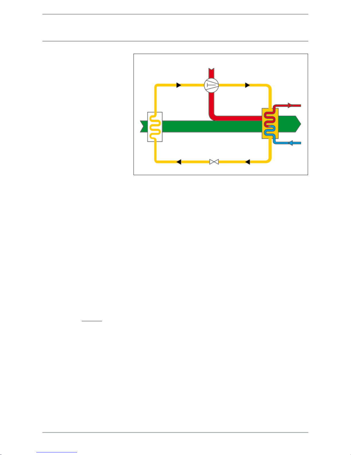
Heat pump principle
The most important contribution to
the heat pump function is made by
the refrigerant (in the following also
referred to as "process medium"). This
evaporates at the lowest temperatures.
If you route outside air or water to a
heat exchanger (evaporator), in which
the process medium circulates, then
that refrigerant extracts the required
evaporation heat from the heat source
and changes from a liquid into a
gaseous state. During this process,
the heat source cools down by a few
degrees. A compressor draws the
process medium in and compresses
it. The increase in pressure also raises
the temperature; in other words,
the process medium is "pumped"
to a higher temperature level. That
requires electrical energy. As the
compressor is of the suction gascooled design, the energy (motor
heat) is not lost, but reaches the
downstream condenser together with
the compressed process medium.
Here, the process medium transfers
its absorbed energy to the circulating
system of the hot water heating
system by being returned into the
liquid state again. An expansion valve
reduces the still prevalent pressure
and the circular process starts again.
Heat pump coefficient of performance
The coefficient of performance
ε
HP
is equal to the quotient of heating
output Q
HP
and electrical power
consumption P
HP
in accordance with
the following equation
It provides a factor, by which yield
exceeds expenditure. The coefficient
of performance is subject to the
temperature of the heat source
and that of the heat consumer. The
higher the heat source temperature
and the lower the heat consumer
temperature, the higher the coefficient
of performance. It relates, as current
value, always to a specific operating
condition.
How doES a HEat pUmp work?
ε
HP
=
Q
HP
P
HP
Main layout of a heat pump refrigeration circuit
Compressor
Inlet line
Gaseous process medium
low pressure
Pressure line
Gaseous process medium
high pressure
Liquid line
Liquid process medium
high pressure
Injection line
Liquid process medium
low pressure
Expansion valve
Flow
Return
Evaporator
Heating
energy
Environmental
energy
Page 8
8 WWW.STIEBEL-ELTRON.COM
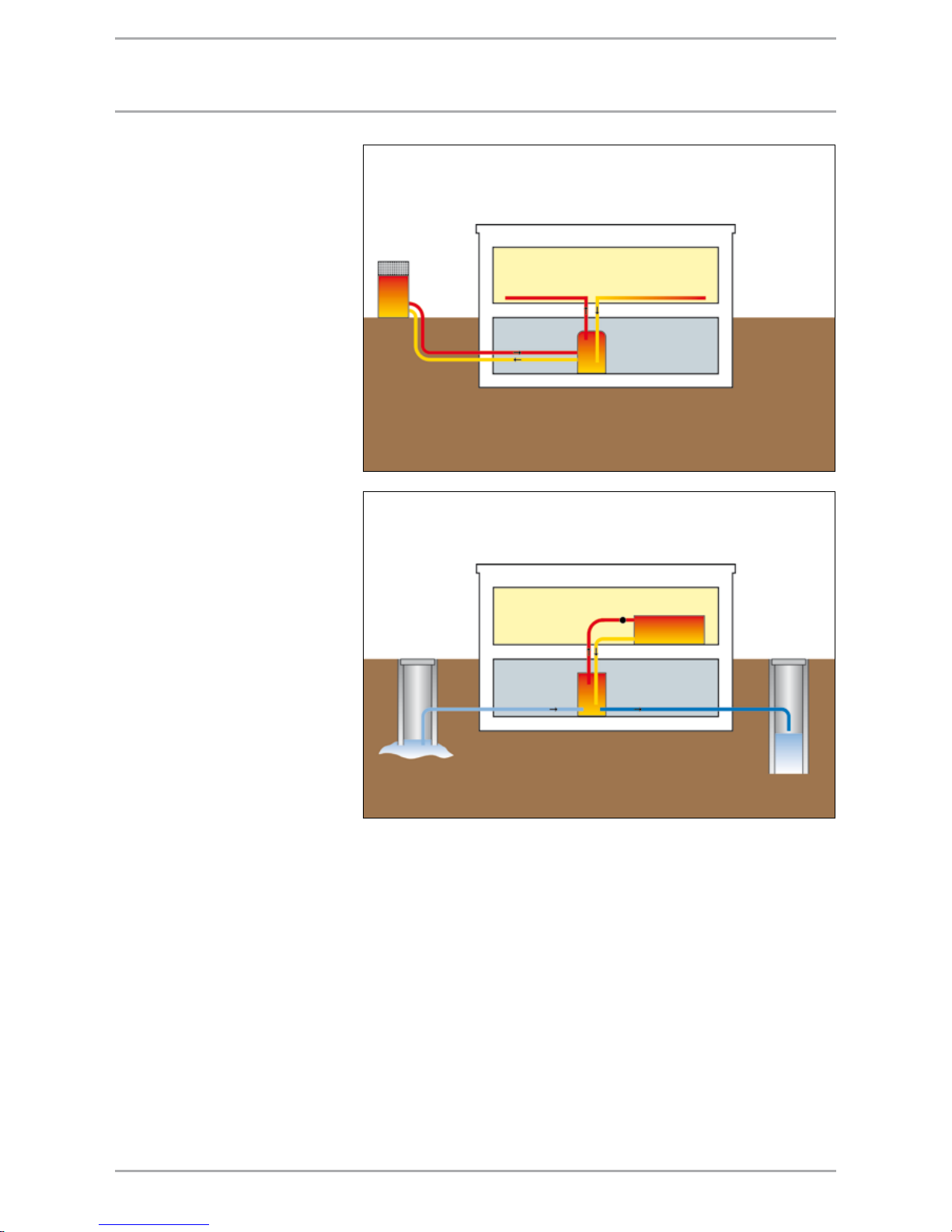
Heat source air
Air heated by the sun is universally
available. Even at temperatures as low
as –20 °C, heat pumps yield sufficient
heat from the outside air. However, air
as heat source has the disadvantage
that it is coldest when the highest
heat demand arises. Although it is
still possible to extract heat from air
as cold as –20 °C, the heat pump
coefficient of performance is, however,
regressive in line with the outside
temperature. It is for that reason,
that in most cases a combination
with a second heat source is required
that boosts the heating system,
particularly during the colder season.
One particular benefit is the ease of
installation of air|water heat pumps,
as no extensive ground work or well
drilling is required.
Heat source water
Groundwater is a good store of solar
energy. Even on the coldest days in
winter, temperatures of +7 °C to +12
°C are achieved - and this is where
its advantage lies. The near constant
temperature level of this heat source
enables the heat pump to achieve a
favourable coefficient of performance
all the year round. Regrettably,
groundwater of adequate quality is
not universally available. Where it is
available, its utilisation is certainly
worthwhile. The use of groundwater
requires the approval of your local
water board [check local regulations].
Utilising this heat source requires the
drilling of a delivery and return well.
Your local water board will advise you
about the possibility of utilising these
waterways.
EnErgy SoUrcES for HEat pUmpS
Main layout of an air source heat pump system
Main layout a groundwater heat pump system
Page 9
9WWW.STIEBEL-ELTRON.COM
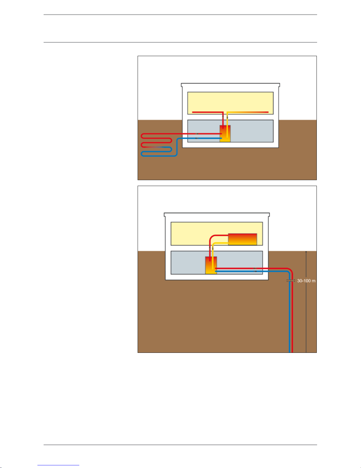
EnErgy SoUrcES for HEat pUmpS
Heat source ground with geothermal
collector
At a depth of 1.2 to 1.5 m, the ground
remains warm enough, even on
colder days, to enable an economical
heat pump operation. However, this
requires the availability of a property
large enough to accommodate a
pipe system for collecting the heat
from the ground. In dry, sandy soil,
the collector can extract between 10
and 15 W/m² and up to 40 W/m² in
ground that carries groundwater.
An environmentally-friendly brine
mixture that cannot freeze and which
transports the yielded energy to
the heat pump evaporator courses
through the pipes. As a rule of thumb,
you would need approximately
two to three times as much ground
area as area to be heated. If your
property is large enough, you have an
inexhaustible reserve of energy and
ideal conditions for a STIEBEL ELTRON
brine |water heat pump.
Heat source ground with geothermal
probe
Geothermal probes that are set up
to 100 metres deep into the ground
by specialist drilling contractors,
require less space. Geothermal probes
comprise a probe foot and endless,
vertical probe pipes made from
plastic. As with geothermal collectors,
a brine mixture that extracts heat from
the ground circulates through the
plastic pipework. The extraction rate is
subject to the ground characteristics,
and generally lies between 30 and
100 W per metre geothermal probe.
Subject to heat pump and ground
conditions, several geothermal probes
can be linked up in a single system.
These systems must be notified to and
possibly approved by your local water
board.
Main layout geothermal probe heat source system
Main layout geothermal collector heat pump system
Page 10
10 WWW.STIEBEL-ELTRON.COM
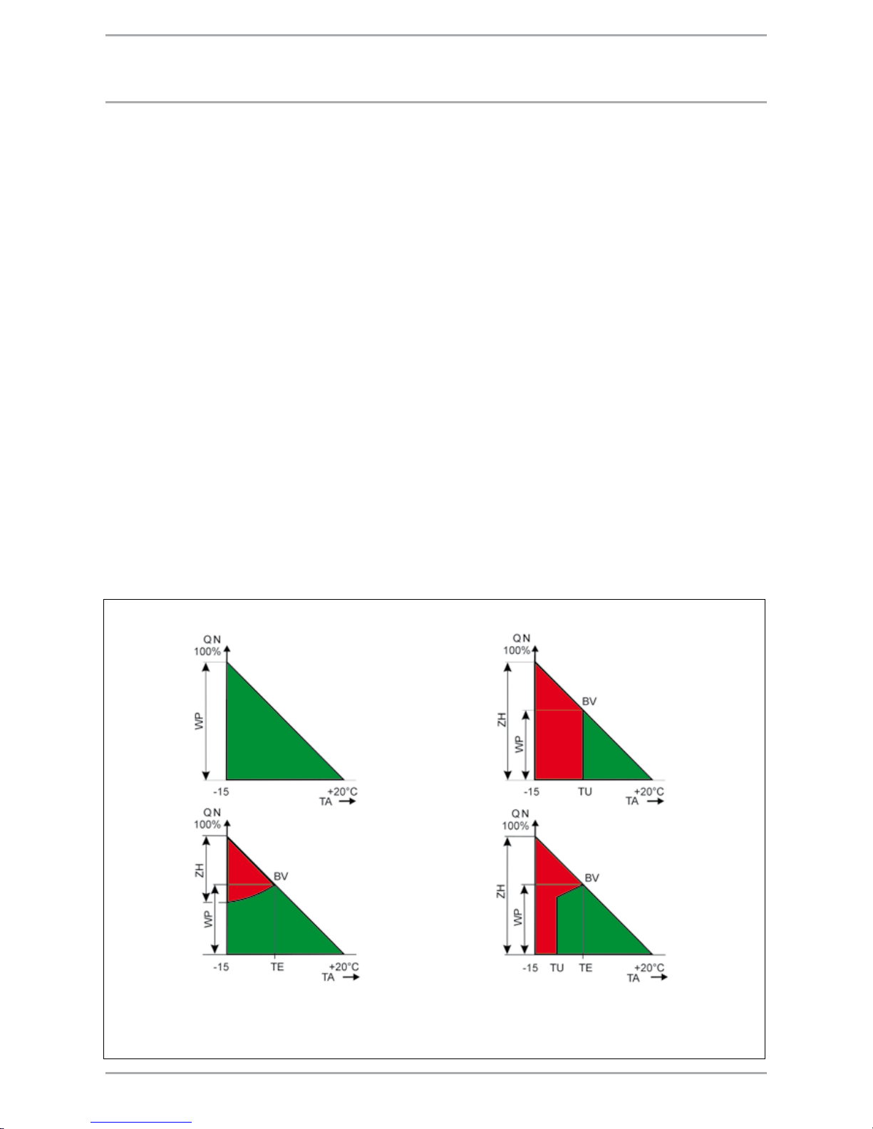
Operating modes
For the different types of heat pump
operation, the heating technology
world uses the following terminology:
Mono-mode
The heat pump is the sole provider
of heating in the building. This
operating mode is suitable for all
low temperature heating systems up
to +60 °C flow temperature.
Mono-energetic
The heating system uses no second
form of energy. The air | water heat
pump operates down to an outside air
temperature of –20 °C. Upon demand,
an electric booster heater is started at
very low outside air temperatures.
HEat pUmp opEratIng modES
Dual-mode - alternative
Down to a fixed outside temperature
(e.g. 0 °C), the heat pump delivers
the entire heating energy. When the
temperature falls below that value,
the heat pump switches itself OFF
and the second heat source takes over
the heating operation. This operating
mode is suitable for all heating
systems up to 90 °C.
Dual-mode - parallel
Down to a certain outside
temperature, the heat pump alone
delivers the required heating energy.
A second heat source starts at low
temperatures. However, contrary
to the dual-mode alternative
operation, the heat pump proportion
of the annual output is higher.
This operating mode is suitable
for underfloor heating systems
and radiators up to +60°C flow
temperature.
Dual-mode - partially parallel
Down to a certain outside
temperature, the heat pump alone
delivers the required heating energy.
The second heat source starts, if the
temperature falls below that value. The
heat pump is stopped if the heat pump
flow temperature is inadequate. The
second heat source supplies the entire
heating output. This operating mode is
suitable for all heating systems above
60 °C flow temperature.
Illustration of the possible operating modes of a heat pump system
mono-mode dual-mode -
alternative
dual-mode partially
parallel
dual-mode - parallel,
mono-energetic
Heat distribution system tv < 60 °C Heat distribution system tv > 60 °C
HP = Heat pump
QN = Heating load
TU = Changeover point
BV = Dual-mode point
ZH = Booster heater
TE = Booster heater start
Page 11

11WWW.STIEBEL-ELTRON.COM
tHE rIgHt HEat pUmp for EvEry applIcatIon
For the use of a water | water heat
pump, groundwater of sufficient
volume and quality must be
available at an economical depth.
You have ideal conditions for a
mono-mode operation, if this heat
source is available to you.
The utilisation of a brine | water
heat pump requires the availability
of property without buildings that
can be used for a geothermal
collector. The property should
be at least two to three times
the area to be heated. These
systems can be operated in monomode in conjunction with a low
temperature heating system.
We help before you start
Take an overview first; our table will
assist you in that. A good analysis,
from the building and heating
technology point of view is crucial.
In new build, generally all kinds of
heat sources can be utilised, i.e. air,
groundwater or ground. You judge
which is the optimum one for you
using the following criteria.
Using an air | water heat pump is
always possible, as the heat source
air is available anywhere. It is
suitable for dual-mode and monoenergetic operation.
Larger systems can be realised by
connecting several heat pumps
together. The electric and hydraulic
connection of brine | water or
water | water heat pumps is easily
achieved with the appropriate
accessories.
Central heating
Specific heat demand 50
W/m² living space, low
temperature heating
system, max. flow
temperature +60 °C
(desirable is +35 °C)
Heat source
Groundwater
exploration via a well
system
Operating mode
mono-mode
Heat pump size subject to
m
2
heated living space
up to 120 m2WPW 7
up to 180 m²
WPW 10
up to 220 m²
WPW 13
up to 300 m²
WPW 18
up to 420 m²
WPW 22 M
up to 440 m²
WPW 26 SET
up to 520 m²
WPW 31 SET
up to 600 m²
WPW 36 SET
up to 720 m²
WPW 40 SET
up to 840 m²
WPW 44 SET
Operating mode
mono-mode
Heat pump size subject to
m
2
heated living space
up to 100 m2WPF/C 5
up to 140 m²
WPF/C 7
up to 180 m²
WPF/C 10
up to 240 m²
WPF/C 13
up to 300 m²
WPF 16
up to 360 m²
WPF 20 SET
up to 420 m²
WPF 23 SET
up to 480 m²
WPF 26 SET
up to 540 m²
WPF 29 SET
up to 600 m²
WPF 32 SET
up to 380 m²
WPF 20
up to 500 m²
WPF 27
up to 800 m²
WPF 40
up t 950 m²
WPF 52
up to 1100 m²
WPF 66
Operating mode
mono-energetic dualmode point -5 °C outside
temperature
Heat pump size subject to
m
2
heated living space
up to 160 m2WPF/C 5
up to 200 m²
WPF/C 7
up to 280 m²
WPF/C 10
up to 340 m²
WPF/C 13
up to 420 m²
WPF 16
up to 520 m²
WPF 20 SET
up to 640 m²
WPF 23 SET
up to 700 m²
WPF 26 SET
up to 760 m²
WPF 29 SET
up to 840 m²
WPF 32 SET
up to 600 m²
WPF 20
up to 760 m²
WPF 27
up to 1200 m²
WPF 40
up to 1560 m²
WPF 52
up to 1880 m²
WPF 66
Operating mode
mono-energetic dualmode point -5 °C outside
temperature
Heat pump size subject to
m
2
heated living space
up to 80 m² WPL 5 N
up to 120 m2WPL 10
up to 180 m²
WPL 13
up to 220 m²
WPL 18
up to 300 m²
WPL 23
up to 360 m²
WPL 33
Operating mode
mono-mode
Heat pump size subject to
m
2
heated living space
up to 200 m2WPL 14 HT
Heat source
Ground
geothermal collectors -
geothermal probe
Heat source
Air
universally available
Page 12

12 WWW.STIEBEL-ELTRON.COM
tHIS coUld bE yoUr SolUtIon
General information
Naturally, all compact heat pumps
from STIEBEL ELTRON can be installed
in all new and existing heating
systems. In many cases, a monomode operation is feasible, so that
no additional, conventional heating
system and associated additional
investment is required, even on
those few exceptionally cold days
of the year. When deciding on the
potential Part of this is of a heat
pump, the heat distribution system
too, and in particular the required
flow temperature, must be given due
consideration. Generally speaking,
low temperature and conventional
heating systems (radiators) can
be supplied by heat pumps. When
developing new systems, allow for
low temperature heating systems with
max. flow temperatures of +55°C.
Existing systems with conventional
heat distribution too can generally be
combined with heat pumps without
requiring major changes. Generally,
such heating systems are designed for
maximum flow temperature of 90 °C.
However, most are oversized making
substantially lower flow temperatures
sufficient on account of subsequently
installed thermal insulation of the
building.
Heat pumps not only provide
heating but also produce hot water
economically.
All STIEBEL ELTRON heating heat
pumps also generate domestic hot
water, e.g. with special accessories,
such as the compact installation
and DHW cylinders. The heat pump
manager provides the automatic
changeover between central heating
and DHW heating operation.
Matching solutions for every
application
For many years, STIEBEL ELTRON
has been producing heat pumps
for all applications. Part of this is
an extensive installation accessory
range, e.g. buffer cylinders, pressure
hoses and control equipment. These
enable an easy and consequently
cost-effective installation. In the
following, two examples of heat pump
installations are shown. Naturally,
alternative installation options are
also feasible.
Design example 1
Water|water heat pump
Operating mode: mono-mode
Mono-mode operation is only feasible
in conjunction with a low temperature
heating system (maximum flow
temperature +60 °C). At a specific
heat demand of 50 Watt/m², suitable
heat pumps offer themselves from the
heating system sizes listed in the table
on page 11.
Important information:
A water analysis is part of the first
design phase.
Two results from that analysis are
relevant to the engineering of the
system: free chlorine and chloride.
Iron and manganese content.
Construct the heat pump system in
accordance with the regulations of
your local water board.
The system can be installed
subject to the availability of
groundwater of adequate quantity
and quality.
Design example 2
Air|water heat pump without
additional boiler
The mono-energetic air | water heat
pump WPL from STIEBEL ELTRON. As
the description suggest, the heating
system requires no second form of
energy. This heat pump operates with
outside air temperatures down to –20
°C where the outside air provides the
heat source. Between –5 °C and –20
°C, the heating water is additionally
heated by a small electric booster
heater integrated into the heat pump.
STIEBEL ELTRON offers the air | water
heat pump WPL in different versions,
from 10 to 30 kW heating output. This
produces adequate heating for small
to large houses with a living space of
up to approx. 500 m².
Installation information:
The unrestricted air flow through
the inlet and discharge apertures
must be assured at all times.
A thermal "short circuit" between
the inlet and discharge apertures
must be prevented. The direction
of the air flow should be in line
with the main wind direction,
where possible. An installation
in a corner is advisable when
selecting an internal installation.
Design the air ducts as directly and
as short as possible.
Maintain as small a clearance as
possible between heat pump and
house to keep pipe runs short.
Select the installation location so
that no noise pollution is caused,
even though these appliances are
extremely quiet.
The heat pump by necessity
creates condensate that must be
drained off in a suitable manner.
For internal installations via a
drain, possibly with a condensate
pump.
Page 13
13WWW.STIEBEL-ELTRON.COM
EnErgy SavIngS ordEr EnEv [gErmany]
Energy Savings Order
The EU Energy Performance of
Buildings Directive obliged Member
States to translate measures regarding
energy and CO
2
reductions by
2006 into their national laws. The
EnEV 2002/2004 already laid down
requirements for new buildings and
introduced the energy performance
certificate. Adhering to the required
limits meets the energy-technical
requirements for new residential
properties to obtain planning
permission [in Germany]. The
EnEV 2007 introduces the energy
performance certificate for existing
residential buildings as well as for
non-residential buildings. The energy
performance certificate details the
energy-technical quality of a building
and retains its validity for ten years.
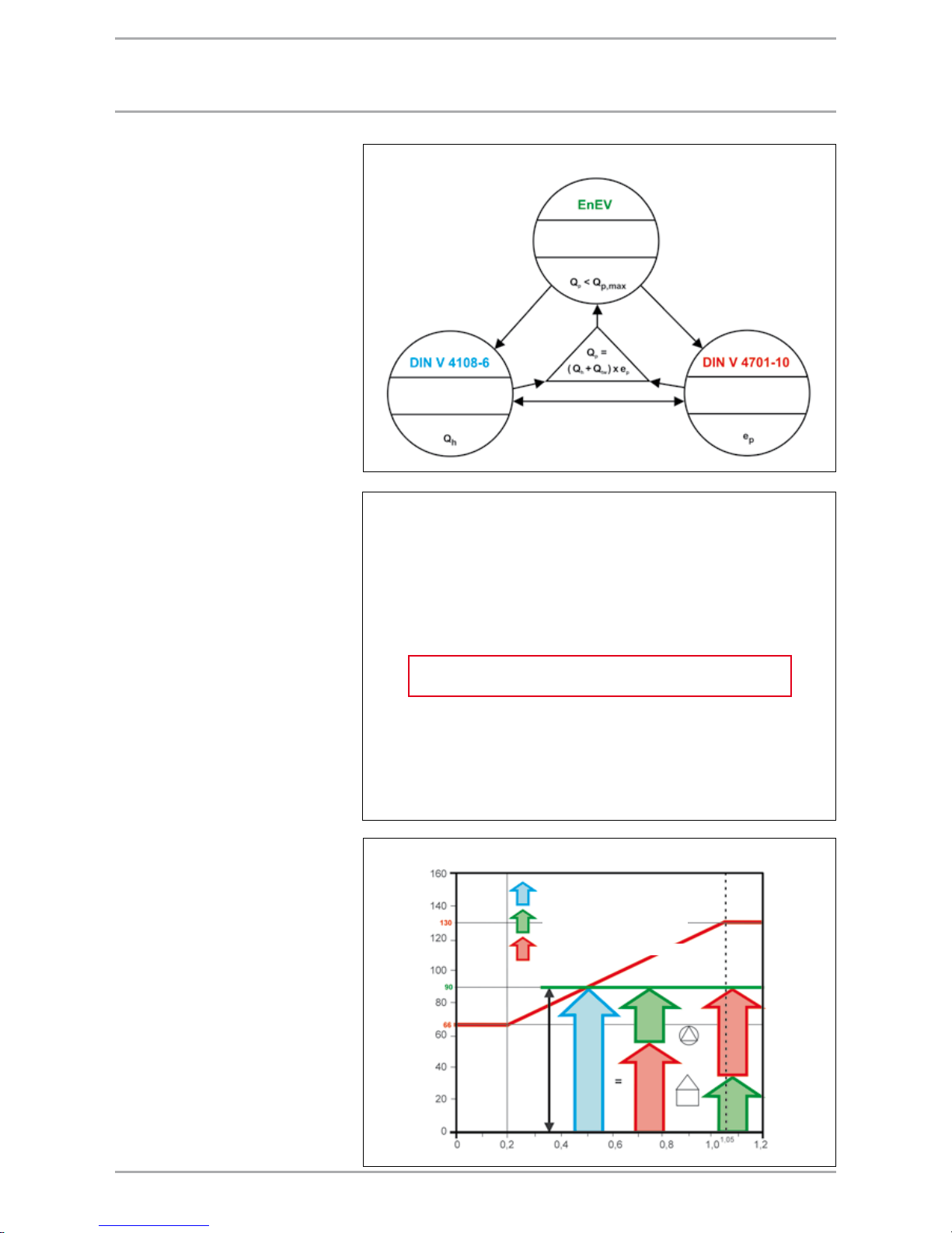
EnEV for residential properties
Calculation of the primary energy
demand Q
P
Energy requirements made of
residential buildings and the system
technology employed are considered in
unison. This global approach enables
an overall statement appertaining
the building envelope and the
system technology to be established
and is based on the primary energy
which allows losses during energy
generation and transmission to be
taken into consideration. To calculate
the annual primary energy demand Q
P
and the system expenditure of energy
value e
P
, the annual heat demand
Q
h
of the building and the available
surface area A
N
must be known. The
system expenditure of energy value
e
P
, which has no dimension and
which relates to the primary energy
for heating, ventilation and DHW,
enables the assessment of the entire
system technology. Furthermore,
this parameter forms the basis for
calculating the annual primary energy
demand Q
P
of a building, and describes
the system efficiency. The lower the
system expenditure of energy value,
the greater the scope for the building
envelope, i.e. the physical building
characteristics. This highlights the
importance of the cooperation between
all engineers and all those involved in
the process.
Calculation of the primary energy demand
Effects of standards
Optional compensations between the building and the system
Total energy demand
Energy efficient version
Energy inefficient version
Ratio external surface area / volume (1/m)
Q
p,max
= permissible annual energy demand (kWh/
(m² p.a.)) relative to the area of available space
Energy savings
calculation
System engineering
calculations
Calculating the structural
physical parameters
Max. annual energy demand
Annual heat demand
System expenditure of energy value
Primary energy
demand
Heating energy
demand
DHW
demand
System expenditure
of energy value
* (QtW fixed value 12.5 kWh/m² p.a. acc. to EnEV)
QP = ( Qh + QtW* ) x e
P
( )
= + x
Building
System
Page 14

14 WWW.STIEBEL-ELTRON.COM
EnErgy SavIngS ordEr EnEv [gErmany]
Outline DIN V 18599
Part 1 General statement procedure, terminology,
zoning and assessing fuel types
Part 2 Demand for useable energy for heating and cooling building zones
Part 3 Demand of useable energy for air treatment with energy
Part 4 Useable energy and net energy demand for lighting
Part 5 Net energy demand of heating systems
Part 6 Net energy demand of domestic ventilation systems
and air heating systems for residential buildings
Part 7 Net energy demand for air handling and air conditioning systems
for non-residential buildings
Part 8 Useable energy and net energy demand for DHW heating systems
Part 9 Net and primary energy demand of CHP systems
Part 10 Utilisation framework conditions, climate data
Supplement 1
Examples
System description - reference system technology
Central Low temperature boilers
heating Pressure-jet boilers
Natural gas
Installation outside the thermal envelope
System temperature 55/45 °C
Hydraulically balanced
Twin-pipe heating system
Distribution lines - unheated area
Riser and connection lines, internal
Dp constant
Pump sized in accordance with demand
WWB Common heat generation with the heating system
(central) Indirectly heated cylinder
Installation outside the thermal envelope
with DHW circulation
Dp constant
Pump sized in accordance with demand
Compensation options
The better the equipment performs,
the lower the requirement for thermal
insulation of the building envelope.
The EnEV opens up interesting
compensation options. The optimum
use of primary energy is ensured
by systems such as heat pumps or
domestic ventilation systems with heat
recovery.
System technology
It is generally recommended to
calculate the heat source expenditure
of energy value in accordance
with the detailed procedure in DIN
4701-10 applying manufacturer's
details. Subject to heat source,
performance factors are applied at
different operating conditions that
can sometimes vary significantly from
standard values. This also applies to
the expenditure as a result of losses
and auxiliary energy, for example
caused by components such as
cylinders and auxiliary drives. STIEBEL
ELTRON offers you a calculation
service or the calculation basics and
software free of charge on CD ROM.
EnEV for non-residential buildings
As part of the EnEV 2007 update,
applicable from the 1st October
2007, the EU Energy Performance of
Buildings Directive" for the statement
of non-residential buildings was
adopted in the form of the extensive
standard DIN V 18599 that determines
the calculations principles.
DIN V 18599 - Energy assessment of
buildings
Contrary to the calculation for
residential buildings to DIN 4108
part 6 and DIN 4701 part 10, the
DIN V 18599 provides a statement
not only for the energy demand for
heating, DHW heating and domestic
ventilation, but also for cooling and
lighting. It comprises 10 parts that
are linked through cross-references.
The essential difference when
considering non-residential buildings
is the assessment of the respective
utilisation profile. The primary energy
demands are no longer simply
dependent on the area and volume
covered by the building envelope,
but additionally relate to different
room temperatures, lighting, air
changes, times of utilisation, density
of occupation and the internal heating
loads. A further update of the EnEV
2007 (scheduled for 1 January 2009)
envisages replacement of the currently
applicable method of calculation for
residential buildings through that
specified in the DIN V 18599.
The reference building procedure
To determine the permissible annual
primary energy demand of a nonresidential building, a reference
building is determined that in
geometry, net floor area, orientation
and utilisation profile matches the
building to be assessed perfectly.
The energy quality of the building
envelope of the reference building
is specified in the EnEV via default
transmission heat transfer coefficient
HT ‘. System technology is also
specified for the reference building
covering heating, DHW heating, air
conditioning, air handling technology
and lighting. For this reference
building, in the first instance the
permissible annual primary energy
demand is determined. Then the
actual value is determined applying
the actual building characteristics
and system technology. To meet the
requirements of the EnEV the existing
annual primary energy demand must
be below the maximum permissible
value of the reference building. Heat
pumps are particularly suitable heat
sources for heating and DHW heating,
as they deliver a more favourable
primary energy statement than the
reference system technology. This
enables the EnEV requirements
to be met quite easily, given a
corresponding quality of the building
envelope.
Page 15

15WWW.STIEBEL-ELTRON.COM
The DIN V 18599 provides a
segregation of the overall building
into various zones, since diverse
areas within the building are used for
various purposes and these require
different conditioning. A zone includes
those rooms within a building that
demand similar parameters on
account of their use (temperature,
ventilation, illumination, internal
loads, daylight provision, technical
equipment) with similar framework
conditions. Every zone has one of
33 programmed utilisation profiles
applied to it (e.g. office, hotel room,
kitchen, toilet, transit areas). The
energy demand for heating and
cooling must be defined separately
for each conditioned zone. Up to
a proportion of 3% of the overall
available floor area, living space may
be appropriately assigned to different
zones than those to which they should
be designated, as long as the internal
loads are not substantially different.
To simplify the calculation process it is
permissible to determine the annual
primary energy demand in accordance
with a single zone model for the
following types of building: Schools,
kindergartens, office buildings, hotels
(without internal swimming pool),
pubs and commercial premises.
However, different framework
conditions must still be applied.
Main areas of use and passages must
account for at least one third of the
total area; the building must only be
equipped with a central system used
to provide DHW and central heating
and must not be cooled. Illumination
must largely correspond to the
reference lighting technology.
The calculations according to DIN V
18599 are extensive and can, because
of the interactions that occur can
only be resolved by iterative means,
only be done with computer-aided
support. STIEBEL ELTRON offers
software solutions for this calculation.
This enables complex calculations
to be carried out, and even includes
manufacturer's data. In this
connection, our specialist department
offers support in all areas concerning
the Energy Savings Order 2007.
EnErgy SavIngS ordEr EnEv [gErmany]
Primary energy demand for non-residential buildings
Primary energy
demand = heating + cooling + steam + DHW + light + auxiliary energy
QP = Q
P.h
+ Q
P.c +
Q
P.m
+ Q
P.w +
Q
P.l +
Q
P.aux
Page 16

16 WWW.STIEBEL-ELTRON.COM
ExpEndItUrE of EnErgy valUES of HEat pUmpS
EnEV – calculation to DIN V 4701-10
The EnEV provides three possible
certification processes:
Diagram process
Tabular process
Detailed process
For the detailed certification process,
verification can be provided using
standard values or manufacturer's
details. Generally, the certification
process with standard values is
sufficient for heat pumps, since their
high efficiency level allows results to
fall below the required expenditure of
energy value.
Where better expenditure of energy
values are demanded by more
stringent subsidy stipulations, e.g.
KFW 40 or KFW 60, these may possibly
be achieved with verification based on
the manufacturer's details.
IT programs or the calculation process
of the EnEV should be applied where
manufacturer's details are to be used.
For calculating the ep figure, STIEBEL
ELTRON offers the software "Energy
efficiency in residential buildings".
Where the certification utilises the
tabular process, draw the expenditure
of energy value eg from the
DIN V 4701-10 according to "Table
C3-4c expenditure of energy value eg
and drive auxiliary energy qg, HE for
heat pumps with electric drive".
Electrically operated heating heat pumps
The heat generation expenditure of energy value is calculated using the annual
performance factor in accordance with the following equation:
e
H,g
= 1 : β
HP
e
H,g
= Expenditure of energy value for the heat pump
β
HP
= Seasonal performance factor of the heat pump, calculated subject to
type of heat pump
Brine|water heat pumps
The seasonal performance factor of brine | water heat pumps is calculated in
accordance with the following equation:
β
HP
= εN x Fϑ x F
∆ϑ
βHP = Annual performance factor of heat pump
ε
N
= Coefficient of performance to EN 14511 at B0/W35
F
ϑ
= Correction factor to table 5.3.7
F
∆ϑ
= Correction factor to table 5.3.8
Water|water heat pumps
The annual performance factor of water|water heat pumps is calculated in
accordance with the following equation:
β
HP
= εN x Fϑ x F
∆ϑ
βHP = Annual performance factor of heat pump
ε
N
= Coefficient of performance to EN 14511 at W10/W35
F
ϑ
= Correction factor to table 5.3.7
F
∆ϑ
= Correction factor to table 5.3.8
Air|water heat pumps
The annual performance factor of air|water heat pumps is calculated in
accordance with the following equation:
βHP = (ε
N
(A-7/W35)
x Fϑ + ε
N
(A2/W35)
x F
ϑ2
+ ε
N
(A10/W35)
x F
ϑ10
) x F
∆ϑ
βHP = Annual performance factor of heat pump
ε
N
= Coefficient of performance to EN 14511 at A-7/W35
ε
N
= Coefficient of performance to EN 14511 at A2/W35
ε
N
= Coefficient of performance to EN 14511 at A10/W35
F
ϑ-7
= Correction factor to table 5.3.10
F
ϑ2
= Correction factor to table 5.3.10
F
ϑ10
= Correction factor to table 5.3.10
F
∆ϑ
= Correction factor to table 5.3.8
Page 17

17WWW.STIEBEL-ELTRON.COM
ExpEndItUrE of EnErgy valUES of HEat pUmpS
Table 5.3.8 - Correction factors FDϑ for deviating temperature differentials at the condenser
Operation
DϑB
(K)
Temperature differential at the test bed DϑM (K) DIN EN 255
3 4 5 6 7 8 9 10 11 12 13 14 15
3 1.000 0.990 0.980 0.969 0.959 0.949 0.939 0.928 0.918 0.908 0.898 0.887 0.877
4 1.010 1.000 0.990 0.980 0.969 0.959 0.949 0.939 0.928 0.918 0.908 0.898 0.887
5 1.020 1.010 1.000 0.990 0.980 0.969 0.959 0.949 0.939 0.928 0.918 0.908 0.898
6 1.031 1.020 1.010 1.000 0.990 0.980 0.969 0.959 0.949 0.939 0.928 0.918 0.908
7 1.041 1.031 1.020 1.010 1.000 0.990 0.980 0.969 0.959 0.949 0.939 0.928 0.918
8 1.051 1.041 1.031 1.020 1.010 1.000 0.990 0.980 0.969 0.959 0.949 0.939 0.928
9 1.061 1.051 1.041 1.031 1.020 1.010 1.000 0.990 0.980 0.969 0.959 0.949 0.939
10 1.072 1.061 1.051 1.041 1.031 1.020 1.100 1.000 0.990 0.980 0.969 0.959 0.949
Table 5.3.7 - Correction factor Fϑ for brine | water heat pumps
Minimum brine temperature at the
evaporator inlet (°C)
Heating circuit design temperature
35°C / 28°C 55 °C / 45 °C
2 1.113 0.917
1 1.100 0.904
0 1.087 0.890
–1 1.074 0.877
–2 1.062 0.864
–3 1.051 0.852
Table 5.3.9 - Correction factor Fϑ for water | water heat pumps
Minimum water temperature at the
evaporator inlet (°C)
Heating circuit design temperature
35°C / 28°C 55 °C / 45 °C
12 1.106 0.892
11 1.087 0.873
10 1.068 0.853
9 1.049 0.834
8 1.030 0.815
Table 5.3.10 - Correction factor Fϑ for air | water heat pumps
Outside air inlet (°C) Heating circuit design temperature
35°C / 28°C 55 °C / 45 °C
–7 0.103 0.080
+2 0.903 0.745
+10 0.061 0.053
Table C3-4c - Expenditure of energy value eg and auxiliary drive energy qgHE for electric heat pumps
Electric heat pump Heating circuit temperature Expenditure of energy value Auxiliary energy
e
g qgHE (kWh/m² p.a.)
Water/Water 55 °C / 45 °C 0.23
3.2 x A
N
-0.1
35°C / 28°C 0.19
Ground/Water 55 °C / 45 °C 0.27
1.9 x A
N
-0.1
35°C / 28°C 0.23
Air/Water 55 °C / 45 °C 0.37
0
35°C / 28°C 0.30
Page 18

18 WWW.STIEBEL-ELTRON.COM
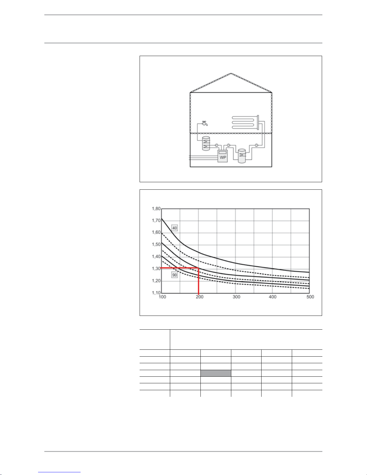
ExamplE 1: brInE | watEr HEat pUmp
Diagram system expenditure of energy value e
p
System description
Brine | water heat pump WPF with 100
litre buffer cylinder and 300 litre DHW
cylinder
DHW heating
Centralised provision; no DHW
circulation; distribution outside the
thermal envelope; indirectly heated
cylinder; installation outside the
thermal envelope; heating heat pump
brine|water powered by electricity.
Ventilation
No mechanical ventilation.
Central heating
Integral heating surface (e.g.
underfloor heating system); individual
room regulation with two-point
controller, switching differential
Xp=2 K; heating system design 35/28
°C; centralised system; horizontal
distribution outside the thermal
envelope, lines running internally;
regulated pump; buffer cylinder
installed; installation outside the
thermal envelope; heating heat pump
brine | water powered by electricity.
Example:
Annual heat demand
60 kWh/m² p.a.
Heated living space 200 m²
Result:
System expenditure of energy value =
1.04
System layout
Diagram system expenditure of energy value e
p
Annual
heating
demand
Heated available area in A
N
in m²
kWh/m² p.a. 100 200 300 400 500
40 1.42 1.17 1.08 1.04 1.01
50 1.31 1.09 1.02 0.98 0.96
60 1.22 1.04 0.98 0.95 0.92
70 1.16 1.00 0.94 0.93 0.90
80 1.11 0.96 0.91 0.89 0.87
90 1.07 0.94 0.89 0.87 0.86
Underfloor heating
system
Ground
Heated available area in AN in m²
System expenditure of energy value e
p
Page 19
19WWW.STIEBEL-ELTRON.COM
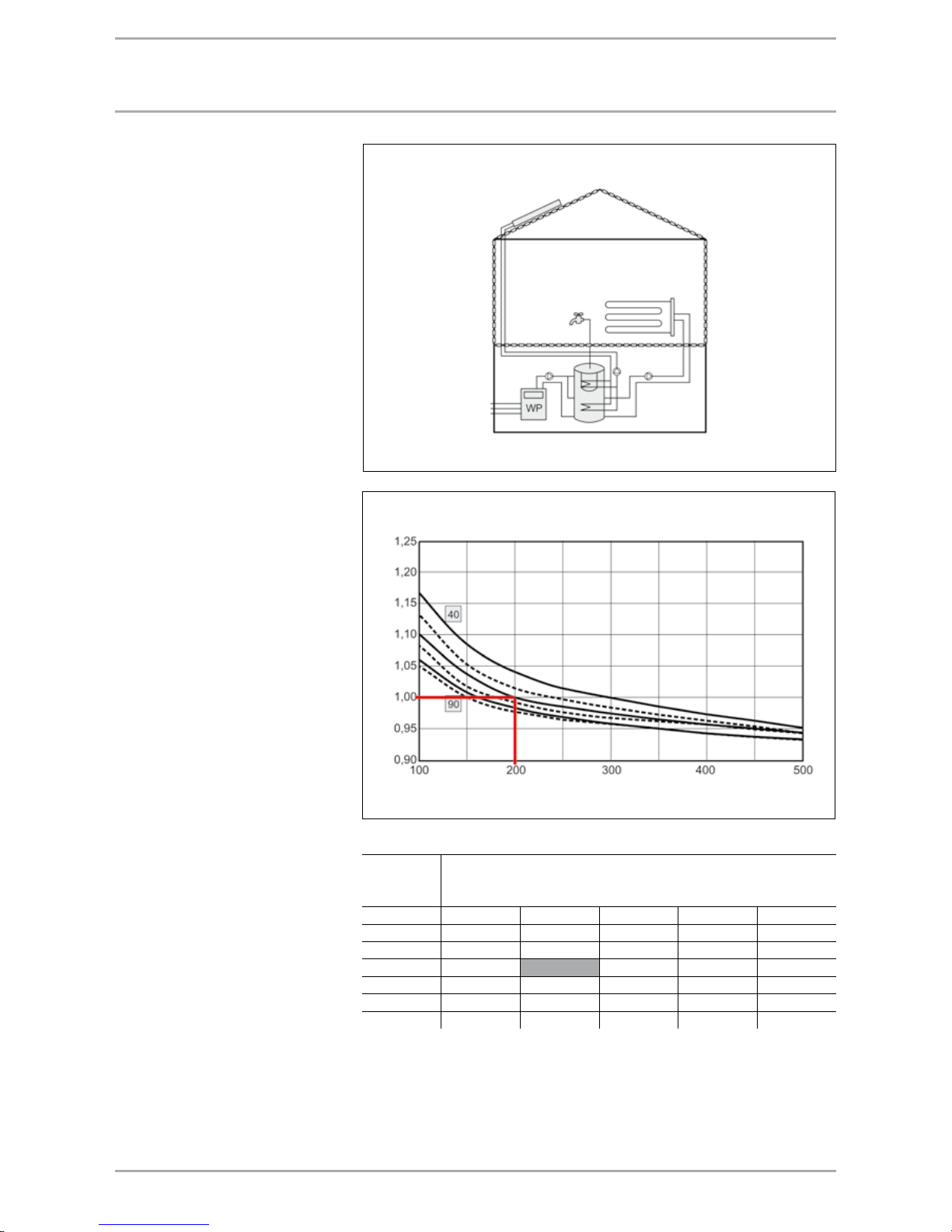
ExamplE 2: aIr | watEr HEat pUmp
Diagram system expenditure of energy value e
p
System description
Air | water heat pump WPL with 200
litre buffer cylinder and 300 litre DHW
cylinder
DHW heating
Centralised provision; no DHW
circulation; distribution outside the
thermal envelope; indirectly heated
cylinder; installation outside the
thermal envelope; heating heat pump
brine | water powered by electricity;
peak load: Electric heater rod.
Ventilation
No mechanical ventilation.
Central heating
Integral heating surface (e.g.
underfloor heating system);
individual room regulation with
two-point controller, switching
differential Xp=2 K; heating system
design 35/28°C; centralised system;
horizontal distribution outside the
thermal envelope, lines running
internally; regulated pump; buffer
cylinder installed; installation outside
the thermal envelope; heating
heat pump air | water powered by
electricity. Electric heater rod.
Example:
Annual heat demand
60 kWh/m² p.a.
Heated living space 200 m²
Result:
System expenditure of energy value =
1.31
System layout
Diagram system expenditure of energy value e
p
Annual
heating
demand
Heated available area in A
N
in m²
kWh/m² p.a. 100 200 300 400 500
40 1.72 1.44 1.35 1.30 1.27
50 1.60 1.37 1.29 1.25 0.23
60 1.52 1.31 1.25 1.23 1.20
70 1.46 1.28 1.22 1.20 1.17
80 1.41 1.25 1.20 1.18 1.16
90 1.37 1.23 1.18 1.16 1.14
Underfloor heating
system
Air
Heated available area in AN in m²
System expenditure of energy value e
p
Page 20
20 WWW.STIEBEL-ELTRON.COM
ExamplE 3: aIr | watEr HEat pUmp wItH Solar
Diagram system expenditure of energy value e
p
System description
Air | water heat pump WPL with 200
litre buffer cylinder and 300 litre DHW
cylinder
DHW heating
Centralised provision; no DHW
circulation; distribution outside the
thermal envelope; indirectly heated
dual-mode cylinder; installation
outside the thermal envelope; heating
heat pump air|water powered by
electricity; peak load: Electric heater
rod; with solar DHW heating.
Ventilation
No mechanical ventilation.
Central heating
Integral heating surface (e.g.
underfloor heating system);
individual room regulation with
two-point controller, switching
differential Xp=2 K; heating system
design 35/28°C; centralised system;
horizontal distribution outside the
thermal envelope, lines running
internally; regulated pump; buffer
cylinder installed; installation outside
the thermal envelope; heating
heat pump air | water powered by
electricity. Electric heater rod.
Example:
Annual heat demand
60 kWh/m² p.a.
Heated living space 200 m²
Result:
System expenditure of energy value =
1.00
System layout
Diagram system expenditure of energy value e
p
Annual
heating energy
demand
Heated available area in AN in m²
kWh/m² p.a. 100 200 300 400 500
40 1.17 1.04 1.00 0.97 0.95
50 1.13 1.02 0.98 0.96 0.94
60 1.10 1.00 0.97 0.95 0.94
70 1.08 0.99 0.97 0.95 0.94
80 1.06 0.98 0.96 0.94 0.93
90 1.05 0.98 0.96 0.94 0.93
Underfloor heating
system
Air
SOLAR
Heated available area in AN in m²
System expenditure of energy value e
p
Page 21

21WWW.STIEBEL-ELTRON.COM
coSt calcUlatIon to vdI 2067
Cost calculation
Calculation in accordance with VDI
2067
To establish the total costs, carry out
the following calculations.
Hours run at full utilisation
VDI 2067 sheet 1 to 6
The hours at full utilisation are
required for calculating the annual
heat demand. The calculation is based
on the number of heating days during
the heating season, the average
building temperature, the average
outside temperature and the lowest
outside temperature.
Energy costs
VDI 2067 sheet 1 to 6
The energy costs result from the
energy consumption, the energy price
and the standing charges.
Operating costs
VDI 2067 sheet 1, table A2
Costs for maintenance, cleaning and
chimney sweeping.
Capital costs
VDI 2067 sheet 1, table A8
Interest and repayments of system
costs.
Maintenance
VDI 2067 sheet 1, table A2
The maintenance costs are calculated
as a percentage of the system costs.
Annuity calculation
The VDI 2067 uses the annuity
method. Part 6 is responsible for
calculations in connection with
heat pumps. The annuity factor
determines the uniform payments in
connection with an investment that
are due annually. The annuity method
provides a dynamic investment
calculation that converts the payments
received and made into equal annual
contributions (annuities). Primarily,
the annuity method is used in the
investment and finance sector. In
addition, it is used in cost calculation
regarding long-term decisions, such
as the selection of processes or
whether to manufacture in-house or
use outside suppliers.
Amortisation calculation
An investment is viable if, with the
given interest rate, an average annual
surplus can be achieved that is greater
or equal to zero. Using the cash
value and the cash value factor the
amortisation can be calculated.
Cash value
The value of one or several capital
sums due in future within the
reference time. The cash value or
present value is the current value of
future receipts or payments resulting
from discounting. The cash value (K0)
is determined when regular equal
payments are made:
a = periodically due retroactive
payments (interest).
Cash value factor
The discounting total factor (cash
value factor, interest cash value
factor, discounting total factor,
capitalisation factor) is one of the
financial-mathematical factors. It
applies interest to the segments g of
a series of payments, taking the rate
of interest and compound interest
into consideration, and adds the cash
values together.
Page 22
22 WWW.STIEBEL-ELTRON.COM
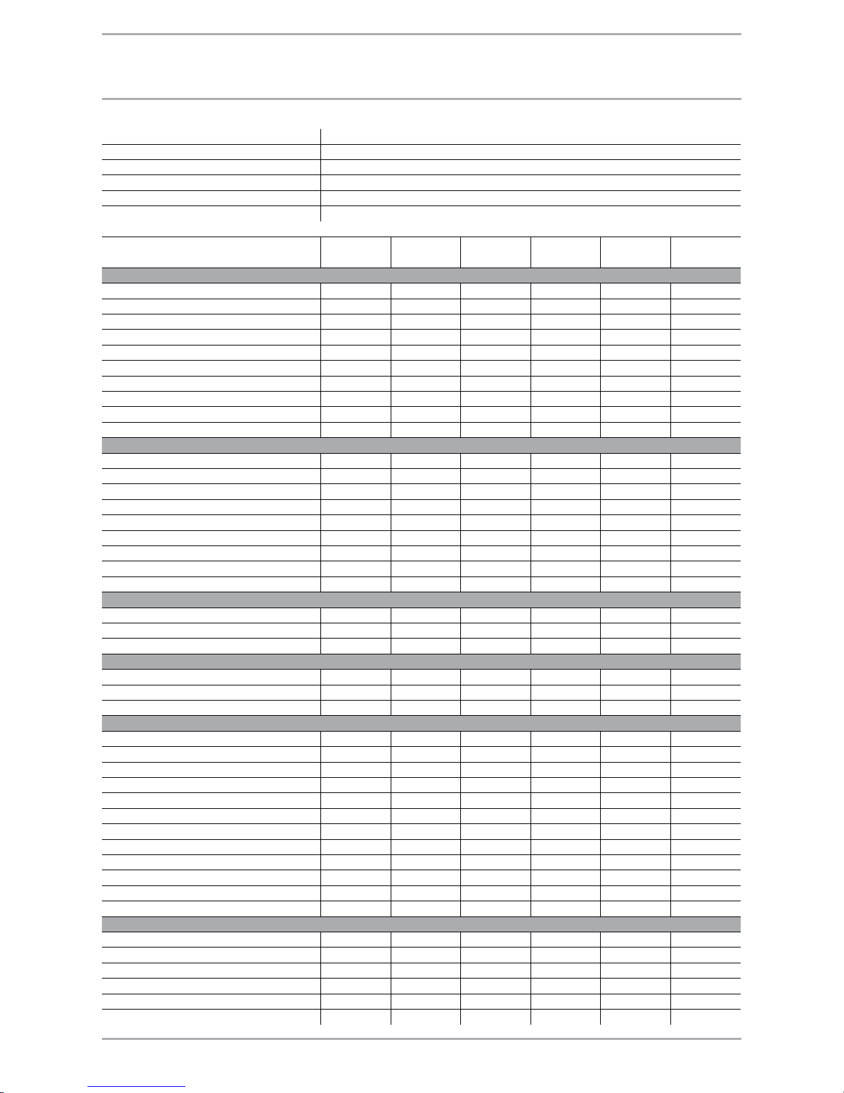
Building heating load 7.0 kW
Hours run at full utilisation 1744
Specific heat demand 50 W/m² (underfloor heating system 35/28 °C)
Number of occupants 4
Energy consumption DHW 2.00 kWh/person/day
Amortisation 0.0963 annuity table (depreciation 15 years with 5% interest)
Air | water heat
pump
Brine | water
heat pump
Water | water
heat pump
Oil heating with
solar
Gas condensing
with solar
Wood heating
(pellets)
1. System details
Energy price heating Ct/kWh 13.00 13.00 13.00 7.50 7.00 4.80
Domestic energy price Ct/kWh 18.00 18.00 18.00 18.00 18.00 18.00
Standing charge p.a. Euro 60.00 60.00 60.00 170.00
Efficiency distribution 0.98 0.98 0.98 0.98 0.98 0.98
Heat source efficiency 1.00 1.00 1.00 0.90 0.99 0.90
DHW efficiency 1.00 1.00 1.00 0.80 0.80 0.80
Annual performance factor 3.60 4.40 4.70
Heating coverage 0.98 1.00 1.00
DHW coverage 0.95 1.00 1.00
Coverage solar heating/DHW 5% 5%
2. Investment
Heat source complete Euro 10.000.00 9.000.00 7.200.00 3.000.00 4.000.00 10.000.00
Heating system with DHW Euro 4.800.00 4.800.00 4.800.00 4.800.00 4.800.00 4.800.00
Installation costs Euro 2.400.00 2.400.00 2.400.00 2.400.00 2.400.00 2.400.00
Electrical installation Euro 1.050.00 1.050.00 1.050.00 350.00 350.00 350.00
Solar thermal system Euro 4.600.00 4.600.00
Oil tank/storage room and gas connection
Euro 2.000.00 1.300.00
Chimney Euro 2.000.00 2.000.00 2.000.00
Heat source system Euro 7.000.00 5.000.00
Total Euro 18.250.00 24.250.00 20.450.00 19.150.00 19.450.00 21.550.00
3. Capital costs
Capital costs Euro 1.758.00 2.336.00 1.970.00 1.845.00 1.874.00 2.076.00
Maintenance Euro 183.00 243.00 205.00 192.00 195.00 216.00
Total Euro 1.941.00 2.579.00 2.175.00 2.037.00 2.069.00 2.292.00
4. Operational costs
Maintenance Euro 150.00 150.00 250.00
Chimney sweep Euro 70.00 70.00 70.00
Total Euro 220.00 220.00 320.00
5. Costs of consumption
Central heating
Annual energy demand kWh 12.208 12.208 12.208 12.208 12.208 12.208
Energy consumption, heating kWh 3.391 2.831 2.650 13.149 11.954 13.841
Energy consumption, booster heater
kWh 249
Annual auxiliary energy demand kWh 200 400 400 200 200 200
DHW
Annual energy demand kWh 2.920 2.920 2.920 2.920 2.920 2.920
Energy consumption DHW kWh 771 664 621 1.825 1.825 3.650
Energy consumption, booster heater
kWh 146
SOLAR
Energy yield kWh 2.070 2.070
Energy consumption solar kWh 160 160
Results
Total energy consumption kWh/p.a. 4.757 3.895 3.672 15.334 14.139 17.691
Emissions CO
2
in total kg/p.a. 3.235 2.648 2.497 4.928 3.690 245
System energy costs Euro/p.a. 688.00 586.00 558.00 1.187.80 1.199.80 875.00
Total system costs Euro/p.a. 2.629.00 3.165.00 2.733.00 3.444.80 3.488.80 3.487.00
Primary energy factor 2.7 2.7 2.7 1.1 1.1 0.2
Primary energy demand kWh/p.a. 12.843 10.516 9.914 16.868 15.553 3.538
ExamplE: coSt calcUlatIon to vdI 2067
Page 23

23WWW.STIEBEL-ELTRON.COM
Defrosting
Removal of a frost or ice coating
from the evaporator of the air|water
heat pump by supplying heat.
STIEBEL ELTRON heat pumps are
defrosted on demand through the
refrigerant circuit.
Process medium
Special term for refrigerant in heat
pump systems.
Dual-mode temperature
Outside temperature, which dictates
when a second heat source is started.
Enthalpy
According to its definition, it is
the sum of internal energy and
displacement work. The specific
enthalpy (kJ/kg) is used for all
calculations.
Expansion appliance
Component of the heat pump between
the condenser and the evaporator for
reducing the condensation pressure to
the evaporation pressure that equates
to the evaporation temperature. In
addition the expansion valve regulates
the injection volume of the process
medium, subject to the evaporator
load.
Fill level
The mass of the process medium
inside the heat pump.
Heating output
The heating output is the available
heat produced by the heat pump.
lg p, h-diagram
Graphic representation of the thermodynamic properties of process media
(enthalpy h, pressure p).
Annual performance factor
Quotient of heat and compressor drive
work over a definite period.
Annual expenditure of energy
The annual expenditure of energy
is the flip-side of the annual
performance factor.
Cooling capacity
Heat flow extracted by the heat pump
evaporator.
Refrigerant
Material with a low boiling point,
which is evaporated by heat
absorption and re-liquefied through
heat transfer in a circular process.
Circular process
Constantly repeating changes in
condition of a process medium by
adding and extracting energy in a
sealed system.
Coefficient of performance (COP)
Factor comprising the heating output
and the compressor drive rating.
The COP can only be quoted as an
actual value at a defined operating
condition. The heating load is always
greater than the compressor drive
rating; hence the COP is always > 1.
Equation symbol: ε
Rated consumption (compressor)
The maximum power consumption
of the heat pump during constant
operation under defined conditions.
It is decisive only for the power
connection to the supply network and
is given on the manufacturer's type
plate.
Standard efficiency
Quotient derived from the used and
related expended work or heat.
Evaporator
Heat exchanger of a heat pump, in
which the thermal flow is extracted
through condensation of the heat
source process medium.
Compressor
Machine for the mechanical
transportation and compression of
vapours and gases. Differentiation
according to the type of construction.
Condenser
Heat exchanger of a heat pump where
the thermal flow is transferred to a
heat transfer medium by condensing a
process medium.
Heat pump
Machine that absorbs a thermal flow
at a low temperature (cold side) and
transfers it through energy supplied
at a higher temperature (hot side).
When using the "cold side" we refer
to refrigerators, when using the "hot
side" we refer to heat pumps.
Heat pump system
Total system, comprising a heat source
and a heat pump system.
Compact heat pump system
Fully-wired appliance, where the
complete refrigerant circuit, incl.
safety and control equipment, has
been manufactured and tested.
Heat source
Medium, from which the heat pump
extracts energy.
Heat utilisation system
Equipment for heat transfer to the
heating system.
Heat source system (WQA)
Equipment for the extraction of
energy from a heat source and the
transportation of the heat transfer
medium between the heat source
and the "cold side" of the heat pump,
including all auxiliary equipment.
Heat transfer medium
Liquid or gaseous medium (e.g. water
or air), with which heat is transported.
Auxiliary energy
Energy required for the operation of
auxiliary equipment.
Off-periods
In Germany, heat pumps can be
stopped, subject to your tariff, by the
power supply utility for 3 x 2 hours
daily.
tErmInology and dEScrIptIonS
Page 24

24 WWW.STIEBEL-ELTRON.COM
SUmmary of formUlaE
Heat amount
Q = m
x c x (t
2
– t1)
Q = Heat amount Wh
m = Water volume kg
c = Specific heat Wh/kgK
1 163 Wh/kgK
t
1
= Cold water temperature °C
t
2
= DHW temperature °C
Heating output
Q = A
x k x ∆ϑ
Q = Heating output W
A = Surface m²
k = Heat transition coefficient
W/m²K
∆ϑ = Temperature differential K
k value
1 + d + 1
αi λ α
a
1
k =
k = k value W/m²K
α
i
= Heat transfer
coefficient, internal W/m²K
α
a
= Heat transfer coefficient,
external W/m²K
λ = Thermal conductivity W/mK
Connected load
P =
m
x c x (t
2
- t1)
T x η
P = Connected load W
m = Water volume kg
c = Specific heat Wh/kgK
t
1
= Cold water temperature °C
t
2
= DHW temperature °C
D = Heat-up times h
η = Efficiency
Heat-up time T
D =
m x c x (t2 - t1)
P
x η
D = Heat-up time h
m = Water volume kg
c = Specific heat Wh/kgK
t
1
= Cold water temperature °C
t
2
= DHW temperature °C
P = Connected load W
η = Efficiency
Pressure drop calculation
∆p = L
x R + Z
∆p = Pressure differential Pa
R = Tubes frictional resistance
L = Pipe length (m)
Z = Pressure drop from the
individual resistances Pa
Individual resistances
Z = Σz x x v
2
ς
2
z = Resistance coefficient
ς = Density
v = Flow velocity (m/s)
Z can be taken from the total z and the
velocity in the pipework in the tables.
Duct work curve
∆p
1
∆p
2
V
1
V
2
)
2
=
∆p1 = Pressure differential Pa
∆p
2
= Pressure differential Pa
V
1
= Air flow rate m³/h
V
2
= Air flow rate m³/h
Mixed water temperature
(m1 x t1) + (m2 x t2)
t
m
=
(m
1
+ m2)
tm = Mixed water temperature °C
t
1
= Cold water temperature °C
t
2
= DHW temperature °C
m
1
= Cold water volume kg
m
2
= DHW volume kg
Mixed water volume
m2 x (t2 - t1)
m
m
=
t
m
- t
1
mm = Mixed water volume kg
m
1
= Cold water volume kg
m
2
= DHW volume kg
t
m
= Mixed water temperature °C
t
1
= Cold water temperature °C
t
2
= DHW temperature °C
DHW volume
mm x (tm - t1)
m
2
=
t
2
- t
1
mm = Mixed water volume kg
m
1
= Cold water volume kg
m
2
= DHW volume kg
t
m
= Mixed water temperature °C
t
1
= Cold water temperature °C
t
2
= DHW temperature °C
Approximate heating load according
to oil consumption
Q
N
= Ba x h x Hu / b
VH
QN = Heating load (kW)
B
a
= Annual oil consumption (l)
Average consumption over the
last five years, minus 75 litres
of oil per person for DHW
heating.
h = Seasonal efficiency [to DIN]
(h = 0.7)
H
u
= Calorific value of fuel oil
(10 kWh/l)
b
VH
= Hours run at full utilisation
(average value 1800 h/p.a.)
Q
N
= Ba / 250
(
Page 25
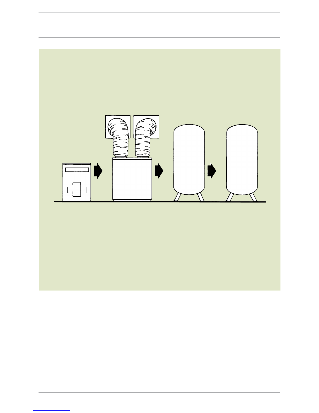
25WWW.STIEBEL-ELTRON.COM
SyStEm dESIgn
Design information
To size heat pump systems accurately,
the following points regarding the
building to be heated or cooled must
be known:
Calculation of heating load to
DIN EN 12831
Calculation of the cooling load to
VDI 2078
Determination of the heating
surface temperature
New build: Determine the
maximum flow temperature
Older building: Determine the
maximum flow temperature
Determine or select the most
favourable heat source
Determine the operating mode of
the heat pump according to the
heating system
Size the heat pump according to
heat demand and operating mode
Power connection conditions and
requirements for the heat pump
control unit
Connection of the heat pump to
the heating system
DHW heating with the heating heat
pump
General regulations and
guidelines/directives
Existing system Heat pump Buffer cylinder DHW heating
Page 26

26 WWW.STIEBEL-ELTRON.COM
rEgUlatIonS and gUIdElInES/dIrEctIvES
The positioning, installation,
adjustment and commissioning of
heat pump systems must only be
carried out by qualified personnel,
giving due consideration to the
operating and installation instructions.
Only a qualified person authorised by
the relevant electricity supply utility
may carry out the heat pump power
connection, giving due consideration
to the relevant wiring regulations and
the conditions applied by the power
supply utility. The installer should also
make the relevant application to the
power supply utility.
Observe the following acts, standards,
regulations and orders during the
installation and operation of heat
pump heating systems in Germany:
Outside Germany, observe all
regulations and guidelines/directives
that may apply to your specific
country.
General conditions:
Building Regulations and others
Observe all relevant local and national
standards since heat pumps represent
"structural systems" in accordance
with the state building regulations
[Germany]. Therefore check with the
local Building Regulations authority
regarding applicable regulations prior
to the installation of a heat pump. The
building owner may need to notify
the relevant authority of the system
installation after the heat pump
installation has been completed. This
notification should be accompanied
by a manufacturer's declaration
that the intended installation will
comply with the requirements
of the building regulations
[Germany]. The requirement for
a permit in accordance with the
"Wasserhaushaltsgesetz" remains
unaffected by this exemption.
Special laws governing the utilisation
of various heat sources
The utilisation of heat latent in the
environment may, be subject to legal
regulations that are designed to
ensure that other private and public
concerns are not impeded, and
that these measures will not exert
dangerous environmental influences.
Groundwater as heat source
The extraction of groundwater
as heat source for a heat pump
and the reintroduction of the
cooled groundwater is regulated
by paragraph 3 sect. 1 no. 6 and
paragraph 3 sect. 1 no. 5 of the
"Wasserhaushaltsgesetzes (WHG)"
[Germany] and is subject to a permit.
The ground is the source of thermal
energy
The extraction of heat by
pipework buried under ground
that are filled with a means for
transporting heat, generally requires
notification to the water board or
a permit. If the ground collector
is in contact with groundwater,
a duty to obtain a permit may be
determined in accordance with
the "Wasserhaushaltsgesetz".
However, this case has not been
finally regulated. It is, nevertheless,
recommended that discussions are
held prior to commencement with the
relevant water authority (see chapter
"Heat source system").
Heat source
The utilisation of the outside air
as heat source with regard to the
entitlement to cool the outside air is
not subject to statutory regulations.
However, observe the technical
instructions regarding protection
against noise emissions [TA-Lärm in
Germany, or local regulations] from
evaporators. The expelled chilled
air may result in a nuisance for
neighbours (LBO sect.18).
Federal Immission Protection Act
(BImSchG) and TA-Lärm [Germany].
Heat pumps are "Systems" in the
sense of the Federal Immissions
Protection Act. The BlmSchG
differentiates between systems
subject to permit (paras. 44, 22) and
systems requiring no permit. Systems
requiring permits are listed finally
in the fourth BImSchV. Heat pumps
of any kind are not listed here. For
that reason, heat pumps are subject
to para. 22 to 25 BlmSchG, i.e. they
must be installed and operated in
such a way that avoidable nuisance is
limited to a minimum. Regarding the
noise emitted by heat pump systems,
observe the technical instructions
appertaining to the protection
against noise as per TA-Lärm [or
local regulations]. For living areas,
the sound pressure levels in the
table LS-Lärm that are subject to the
surrounding development have been
set as emission values.
TA-Lärm (VDI 2058).
The following sound pressure levels at
the neighbours' windows must not be
exceeded:
In commercial residential areas
day 60 dB(A)
night 45 dB(A)
In general residential areas
day 55 dB(A)
night 40 dB(A)
In exclusively residential areas
day 50 dB(A)
night 35 dB(A)
Page 27

27WWW.STIEBEL-ELTRON.COM
rEgUlatIonS and gUIdElInES/dIrEctIvES
DIN standards
– DIN EN 12831 Heating systems in
buildings – procedure to calculate
the standard heating load.
– DIN 4108 Thermal insulation and
energy saving in buildings.
– DIN 4109 Sound insulation in
buildings.
– DIN 8901 Refrigerating systems
and heat pumps – protection of
the ground, groundwater and
surface water – technical safety,
environmental requirements and
test.
– DIN 4701-10 Energy assessment of
heating and air handling system:
Heating, DHW heating, ventilation.
VDI guidelines
– VDI 2067 Efficiency of technical
building systems.
– VDI 2068 Measuring/monitoring
and control equipment in heating
systems with water as heat transfer
medium.
– VDI 2715 Noise reduction in hot
water heating systems.
– VDI 4640-2 Thermal utilisation of
the ground – ground source heat
pump systems.
– VDI 4650 (Draft) Heat pump
calculations. Abridged procedure for
calculating the annual expenditure
of energy values of heat pump
systems.
– VDI 2078 Cooling load calculation
for air conditioned rooms.
Regulations regarding the water side
– DIN EN 806 Technical rules for DHW
installations.
– DIN 4708-1 Central DHW heating
systems – part 1: Terminology and
calculation principles.
– DIN EN 378 Refrigeration systems
and heat pumps – technical safety
and environmental requirements.
– DIN EN 14511-1 to 4 Air handling
units, chillers and heat pumps with
electrically operated compressors
for central heating and cooling –
part 1: Terminology, part 2: Test
conditions, part 3: Test procedures,
part 4: Requirements.
– DIN EN 12828 Heating systems in
buildings - Designing hot water
heating systems.
– TRD 721 Safety equipment to
prevent excess pressure; safety
valves for steam boilers category II.
– DVGW Code of Practice W 101
Guideline for protected potable
water areas, part 1: Protected
groundwater areas.
– DVGW Code of practice W501
Potable water heating and routing
systems - technical measures for the
reduction of the growth of legionella
bacteria – engineering, installing,
operating and modernising potable
water installations.
Regulations regarding the power side
– VDE 0100 Regulations for the
installation of HV systems up to
1000 V.
– VDE 0105 Regulations for the
operation of three-phase systems.
– VDE 0700 Safety of electrical
equipment for domestic use and
similar purposes.
Accident prevention instructions
by the governing body of the trade
associations
– BGV D4 Accident prevention
instructions; refrigerating
equipment, heat pumps and cooling
facilities.
Additional standards and regulations
for dual-mode heat pump systems.
Observe the following acts, standards,
regulations and orders during
the installation of an additional
combustion system for solid, liquid or
gaseous fuels:
Combustion Order [or local/national
equivalent]
– Feu Vo part II, para. 4, sect. 2, sect.
4
– DIN EN 267 Oil combustion system
– technical rules - oil combustion
installation (TRÖ) - test.
Safety principles
– DIN 4787 Oil atomisation burners,
terminology, technical safety
requirements, testing, identification.
– DIN EN 12285-1 Factory-produced
steel tanks – part 1: Horizontal
single or twin-wall cylindrical tanks
for the subterranean storage of
combustible and non-combustible
liquids that represent a risk to
groundwater.
– DIN EN 12285-2 Factory-produced
steel tanks – part 2: Horizontal
single or twin-wall cylindrical tanks
for the above-ground storage of
combustible and non-combustible
liquids that represent a risk to
groundwater.
– DIN 6618-1 Vertical steel containers
(tanks), single wall, for above-
ground storage of combustible
and non-combustible liquids that
represent a risk to groundwater.
– DIN 6619-1 Vertical steel
containers (tanks), single wall, for
subterranean storage of combustible
and non-combustible liquids that
represent a risk to groundwater.
– DIN 6620-1; Cylinder banks (tanks)
made from steel for the above-
ground storage of combustible
liquids, safety category A III.
– DIN 6625-1 Locally manufactured
steel containers (tanks), for above-
ground storage of combustible
liquids safety category A III that
represent a risk to groundwater
and non-combustible liquids that
represent a risk to groundwater.
– DIN 18160-1; Flue systems.
– DIN 18381 VOB Payment and
contract order for construction
services – part C: General technical
contract conditions for construction
services (ATV) – gas, water and
drainage installation systems inside
buildings.
DVGW guidelines
(DVGW Codes of practice)
– TRF 1996 Technical rules for LPG.
– G 430 Guideline for the installation
and operation of low pressure gas
tanks.
– G 600 Technical rules for gas
installations.
– G 626 Technical rules for the
mechanical routing of flue gases for
open flue combustion equipment in
flue and central ventilation systems.
– G 666 Guidelines for the cooperation
between the gas supply utilities and
the contract installation companies.
Page 28

28 WWW.STIEBEL-ELTRON.COM
HEatIng load calcUlatIon
Heating load
Firstly determine the required heating
load of the building. Observe the
calculation to DIN EN 12831 for
reliable quotations and design.
The heating load can also be
estimated for dual-mode heat pump
systems with an existing heat source.
1. Subject to the heated living space
See adjacent table for the heating
load per m² living space.
Q
N
= Living space x Watt/m²
2. Subject to oil consumption
The annual consumption can be
determined from the average oil
consumption over the last five years.
Q
N
= Ba x h x Hu / b
VH
QN = Heating load (kW)
B
a
= Annual oil consumption (l)
h = Seasonal efficiency [to DIN] (h
= 0.7)
H
u
= Calorific value of fuel oil
(10 kWh/l)
b
VH
= Hours run at full utilisation
(average value 1800 h/p.a.)
Brief formula
Q
N
= Ba / 250
3. Subject to gas consumption
The annual consumption can be
determined from the average gas
consumption over the last five years.
Q
N
= Ba x h / b
VH
QN = Heating load (kW)
B
a
= Annual gas consumption (kWh)
h = Seasonal efficiency [to DIN] (h
= 0.8)
b
VH
= Hours run at full utilisation
(average value 1800 h/p.a.)
Detached or two-family home
Thermal insulation of
the external wall
Window Floors W per m²
living space
no single glazed 1 160
no single glazed 2 140
no double glazed 1 to 2 100
yes double glazed 1 to 2 80
yes low-E glass 1 to 2 50
Page 29
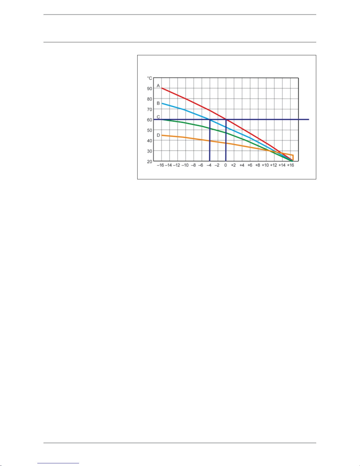
29WWW.STIEBEL-ELTRON.COM
flow tEmpEratUrES of HEatIng SUrfacES
Heating surface temperature
The flow temperature of the heating
system is decisive for the application
options and the operating mode of
the heat pump. Heating systems that
require a flow temperature in excess
of +60°C can only be operated in
dual-mode together with a second
heat source. The changeover point
of the heat pump is determined not
only by the heating output of the heat
pump, but also by the sizing of the
heating surfaces. Radiator heating
systems used to be sized around a
flow temperature of +90°C. Today,
retrofitting thermal insulation or
oversizing generally means, that a
flow temperature of only +70°C or
less is generally required. The heating
surfaces of new systems should be
sized around a flow temperature of no
more than +55°C to enable a monomode operation.
Example:
Up to what outside temperature
can a heating system with a flow
temperature of +75°C (heating
curveB) be operated with a heat
pump operating with a flow
temperature of up to +60°C? In this
example, the point of intersection
between heating curve B and the max.
heat pump flow temperature of +60°C
arrives at an outside temperature
of –4°C. The application limit of
this heat pump therefore lies at an
outside temperature of – 4°C because
of the heat distribution system. It is
often noted in practice that, through
external and internal energy recovery,
the heating limits can be extended to
meet lower temperatures. This means
that the heat pump covers a higher
percentage of the annual heating
load.
Rule of thumb:
The lower the flow temperature of the
heating system, the higher the output
of the heat pump.
According to the above diagram the following flow temperatures produce the
following changeover points to start the second heat source:
Curve A: Flow temperature 90°C changeover point – 0°C OT
Curve B: Flow temperature 75°C changeover point – 4°C OT
Curve C: The flow temperature is lower than +60 °C, enabling the heat pump
to operate in mono-mode.
Curve D: The flow temperature is lower than +60 °C, enabling the heat pump
to operate in mono-mode.
Flow temperatures for the corresponding outside temperatures
Heating flow temperature
External temp
Heat pump
flow temp.
Page 30
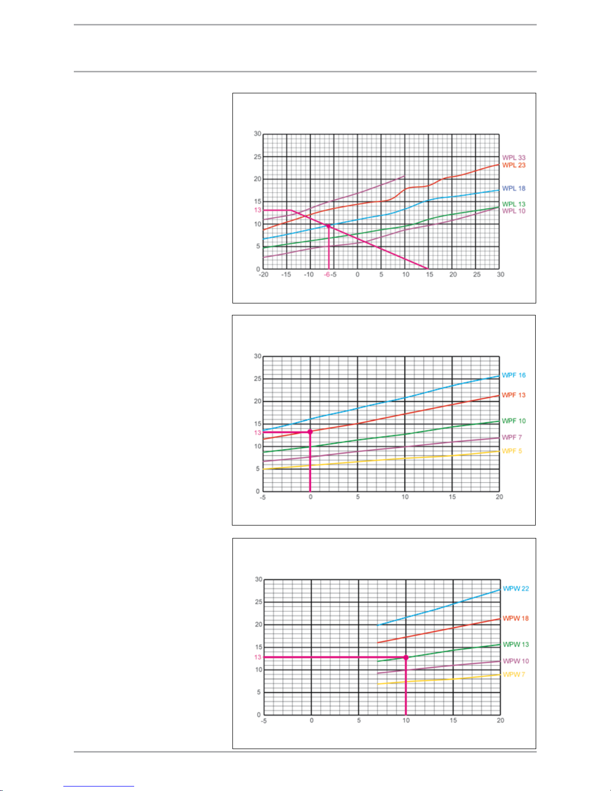
30 WWW.STIEBEL-ELTRON.COM
SIzIng of HEat pUmpS
Sizing of heat pumps
Some electricity supply utilities can
shut down the power supply of heat
pumps for specific periods in return
for favourable tariffs. However, the
heat demand of the building must be
covered 24 hours per day. That means
that the building heating load must be
raised by a factor of 1.1.
Q
HP
= Q
Nbuil.
x 1.1
Air | water heat pumps
The heating output of air | water
heat pumps is subject to the
outside temperature. This has the
disadvantage that the heating output
of the heat pump also falls with
falling outside temperatures, whilst
the heating load actually increases.
This is why air | water heat pumps are
operated in mono-energetic mode.
Brine | water or water | water heat
pumps
As the heat source offers a near
constant temperature throughout the
year, the heating output of the heat
pump is constant. These heat pumps
are operated in mono-mode.
Sizing air|water heat pumps
Sizing brine|water heat pumps
Sizing water|water heat pumps
Air inlet temperature °C
Heating output (kW)
Heat source temperature °C
Heating output (kW)
Heat source temperature °C
Heating output (kW)
Page 31

31WWW.STIEBEL-ELTRON.COM
sizing example
Example:
Air | water heat pump sizing. The
illustration shows the relationship
between the heat demand and the
heating output of the heat pump. The
intersection of the curves provides the
dual-mode point (start of the second
heat source). The dual-mode point
in mono-energetic operation should
lie between an outside temperature
of –3 °C and –7 °C to cover a large
proportion of the annual heat demand
with the heat pump (see table).
Sizing example
The example is a house with a
heat demand of 11.0 kW. The heat
distribution system comprises low
temperature radiators, designed for
55/45 (55 °C flow temp. at –14 °C
outside temperature). The dual-mode
point should be between –3 °C and
–7 °C.
Result:
The required heating output of the
heat pump for an underfloor heating
system and six hours power-OFF
(factor 1.1)
11.0 kW x 1.1 = 12.0 kW.
The WPL 18, that independently covers
a heat demand down to –7 °C outside
temperature and an annual heating
proportion of 98%, was selected.
Annual coverage by the heating heat pump
Dual-mode
point
Parallel (mono-energetic) operation; coverage according to climate zone
°C –10 °C –12 °C –14 °C –16 °C –18 °C
– 12 1.00 1.00 1.00 0.99 0.98
– 10 1.00 1.00 0.99 0.98 0.97
– 8 1.00 0.99 0.98 0.97 0.96
– 6 0.99 0.99 0.98 0.97 0.95
– 4 0.99 0.98 0.97 0.95 0.93
– 2 0.98 0.96 0.94 0.92 0.90
0 0.96 0.93 0.90 0.87 0.85
+ 2 0.92 0.88 0.85 0.81 0.77
+ 4 0.87 0.83 0.79 0.74 0.69
+ 6 0.81 0.77 0.72 0.67 0.62
+ 8 0.75 0.71 0.65 0.59 0.52
Air inlet temperature °C
Heating output (kW)
Air | water heat pump sizing, with inverter technology
Air inlet temperature °C
Heating output (kW)
Air | water heat pump sizing, with
inverter technology
These heat pumps are operated in
mono-mode. Regulating the speed
matches the heat pump heating
output to the heating load of the
building.
Page 32
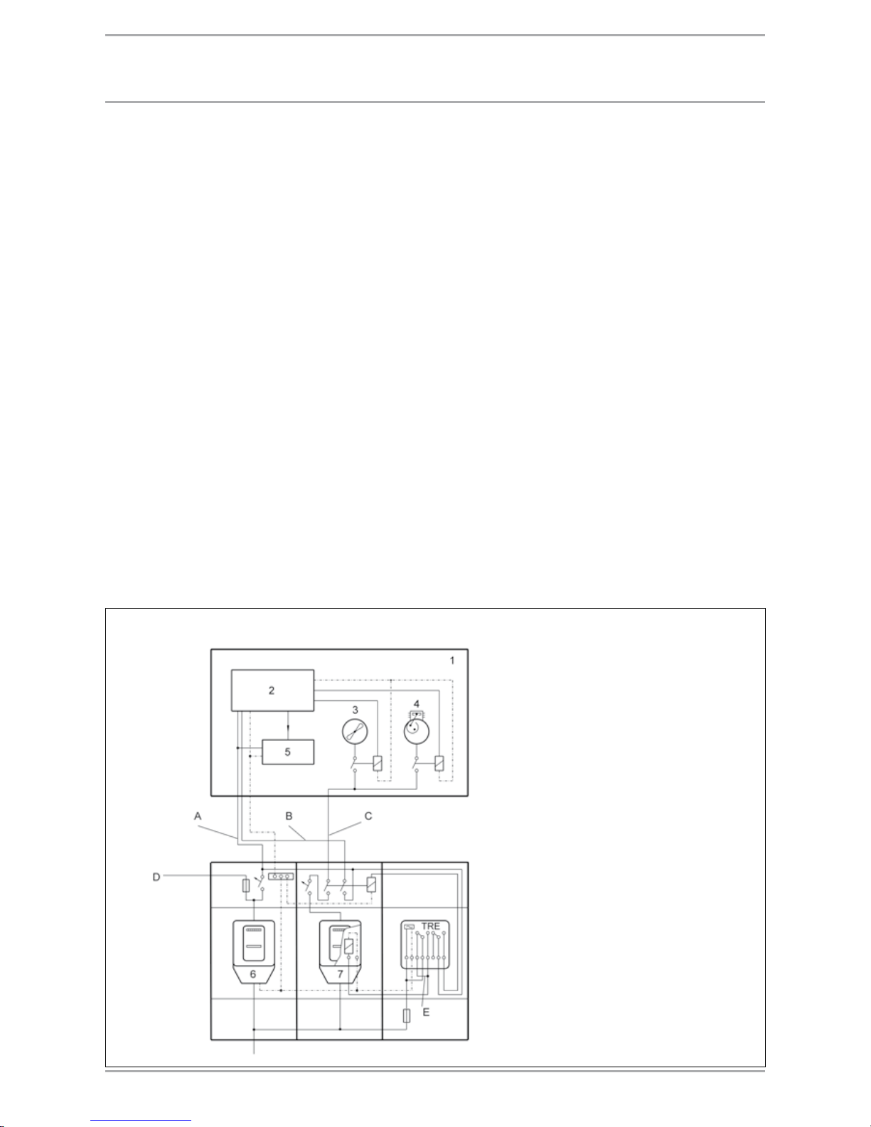
32 WWW.STIEBEL-ELTRON.COM
Application procedures
The following details are required to
assess the effect of the heat pump
operation on the grid of your local
power supply utility:
User address
Location of the heat pumps
Operating mode according to all
tariffs (domestic, agricultural,
commercial, professional and
other demand)
Intended operating mode of the
heat pump
Heat pump manufacturer
Heat pump type
Connected load in kW
Maximum starting current in amps
(manufacturer's details)
Heating load of the building in kW.
Power supply
The electricity required to drive
heat pumps may be classified as
domestic power consumption. In
some countries, the local power
supply utility needs to approve the
installation of heat pumps for central
heating purposes. Ask your local
power supply utility about their
connection conditions for the specified
appliance. It is of particular interest
to check, whether a mono-energetic
heat pump operation is feasible in
your region. Information regarding
standing charges and supply tariffs,
the possibility of utilising favourable
night tariffs and possible shutdown
periods are also important. Your local
power supply utility will be a valuable
contact in these matters.
Requirements for the electrical
installation of heat pumps
Observe the technical connection
conditions of your local power
supply utility.
For information regarding the
necessary switching and metering
equipment, contact your power
supply utility.
powEr SUpply and tarIffS
Installation example for a heat pump system with ripple control receiver
Earth conductor not shown
1 Heat pump system
2 Control unit
3 Fan or pump
4 Compressor
5 Aux. drive
6 Domestic electricity meter
7 Heat pump meter
A Unregulated main power circuit
B Regulated control voltage circuit
C Regulated main power circuit
D To the power distribution board
E For excitation with high tariff power
Page 33

33WWW.STIEBEL-ELTRON.COM
IntEgratIon Into tHE HEatIng SyStEm
Buffer cylinder
For a perfect operation, heat pumps
require a minimum flow rate of
heating water. A buffer cylinder is
recommended to ensure a troublefree heat pump operation. Buffer
cylinders (cylinder SBP) provide
hydraulic separation between the flow
rate in heat pumps and that in the
heating circuits. The flow in the heat
pump circuit remains constant if, for
example, the flow rate in the heating
circuit is reduced by thermostatic
valves.
Convector heating systems are
generally filled with a small amount
of water. For such systems, a buffer
cylinder of appropriate size should be
installed, to prevent frequent cycling
(start and stop) of heat pumps.
A buffer cylinder is also required for
the defrost operation of air | water
heat pumps.
Subject to tariff, heat pumps can be
switched off by some electricity supply
companies during peak periods.
Therefore, size the volume of the
buffer cylinder so that with a heating
system that cools down quickly (i.e.
radiators), the stored heat will be
adequate to cover the heat demand
during the above-mentioned powerOFF periods to prevent a rapid cooling
down of the building.
Benefits of buffer cylinders:
no modification of the sizing of
existing system pipework
no flow noise in the heat
distribution system
no replacement of the circulation
pump of existing heating systems
constant water flow rate through
the heat pump
no loss of comfort during the
power-OFF period
Benefits of applications without buffer
cylinder:
(in conjunction with underfloor heating)
less space requirement
lower investment outlay
higher annual performance factor
Heat pump with overflow facility
Heat pump with separating cylinder (low loss header)
1 Heat pump
2 Control unit
2a Temperature sensor
3 Circuit pump
4 Overflow valve
5 Heating circuit
1 Heat pump
2 Control unit
2a Temperature sensor
3 Circuit pump
4 Overflow valve
5 Heating circuit
6 Buffer cylinder
Page 34

34 WWW.STIEBEL-ELTRON.COM
Heating pipework
Use flexible pipes when integrating
heat pumps into the pipework. Also,
install an additional expansion vessel
because of the greater water volume
and the possible switching OFF of
the heat source. The heat pump is
protected in accordance with DIN
4751 sheet 2. A buffer cylinder is not
required for systems large in mass
(underfloor heating system). If no
buffer cylinder is installed in the
system, fit the overflow valve between
the flow and return lines so that the
minimum heat pump flow rate is
maintained.
Structure-borne noise transfer
To prevent structure-borne noise
transfer to the pipework (possibly
also vibration transfers from central
heating circuit pumps), the installation
of hoses into the water pipework is
required. Use anti-vibration pipe clips.
Circulation pumps in the heat pump
circuit
When using a SBP 200 E or SBP 700 E
(buffer cylinder) and the heat pump
compact installation WPKI 5, size
the corresponding circulation pump
(cylinder primary pump) for the
heat pump in accordance with the
"Circulation pump" selection table.
Second heat source
For dual-mode systems, always
connect the heat pump into the return
of the second heat source (e.g. oil
boiler).
Note: In accordance with the small
combustion system order (1st
BImSchV) [or local regulations]
para 2: Dual-mode heating systems
para 15: The emissions test for the
second heat source is not required
with repeated supervision.
Dual-mode heat pump system
Mono-energetic heat pump system
HEat pUmpS wItH bUffEr cylIndEr
Page 35

35WWW.STIEBEL-ELTRON.COM
HEat pUmpS wItHoUt bUffEr cylIndEr
Installation without buffer cylinder
If heat pumps in a heating system are
installed without a buffer cylinder,
observe the following information:
A constant heat pump flow rate is
required to enable the heat pump
to function correctly. This must be
at least 20% of the nominal flow
rate. Particularly for air | water heat
pumps, other higher minimum flow
rates may be required. Observe the
product documentation. Constant
flow rates are primarily achieved with
area heating systems, where no zone
valves are used in case of several
heating circuits. To avoid contravening
the Energy Savings Act [Germany],
an appropriate dispensation must
be applied for from the Building
Authorities if no zone valves are
installed. For example, if there are
no zone valves installed in the living
room, the room temperature can be
captured by the FE 7 / FEK remote
controller, which in turn complies
with the requirements of the Energy
Savings Act [Germany].
With air | water heat pumps, the
minimum flow rate specified in the
following table must be ensured.
Minimum flow rate
Heat pump m³/h
WPL 10 0.4
WPL 13 E 1.0
WPL 18 E 1.2
WPL 23 E 1.4
WPL 13 cool 1.2
WPL 18 cool 1.7
WPL 23 cool 2.2
WPL 33 1.4
Mono-mode brine | water heat pump without buffer cylinder
Reference room without zone valve
Room temperature regulation via heat
pump remote control FE 7
Overflow valve ÜV required to prevent
flow noise
Minimum circulation volume on the heating side 20% of the nominal flow rate of the heat pump
Mono-energetic air | water heat pump without buffer cylinder
Reference room without zone valve
Room temperature regulation via heat
pump remote control FE 7
Overflow valve ÜV required to prevent
flow noise
Observe the minimum water circulation volume on the heating side.
Page 36
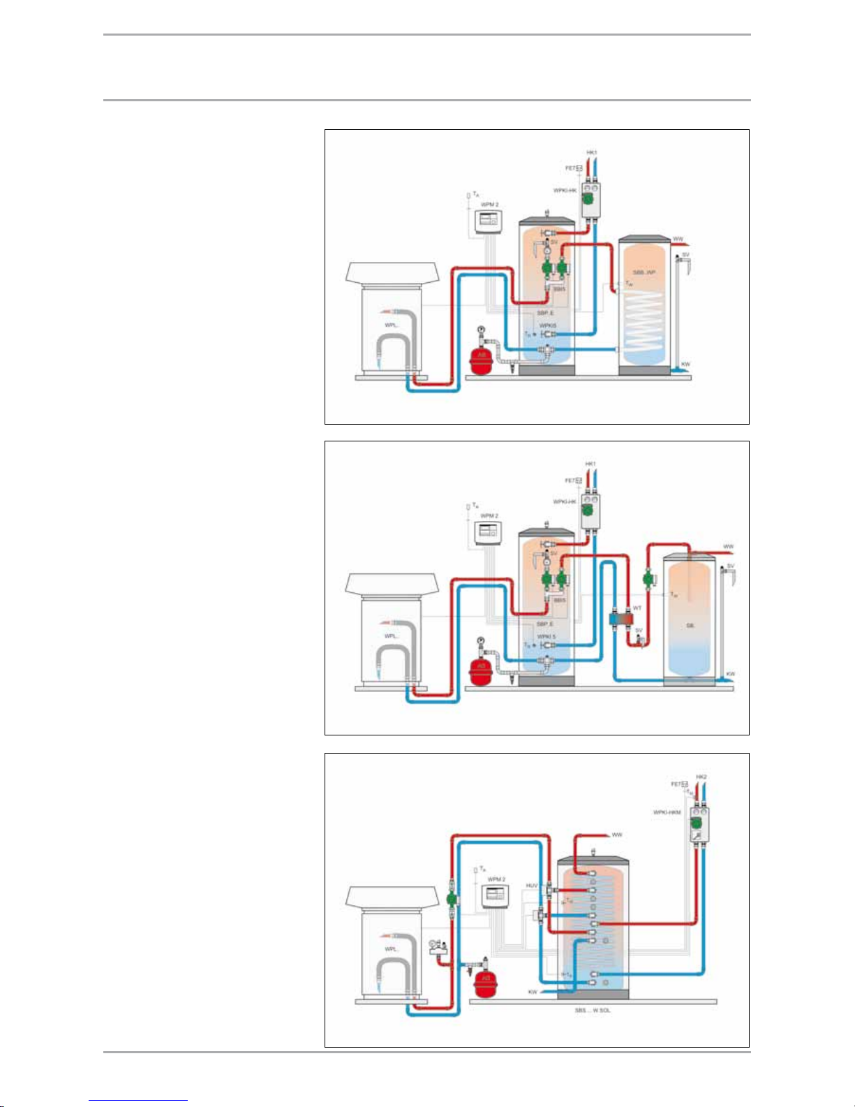
36 WWW.STIEBEL-ELTRON.COM
dHw HEatIng wItH HEat pUmpS
DHW heating with heat pumps
DHW heating is possible with all
STIEBEL ELTRON heat pumps. The
wide range of applications and the
many options of combining heat
pumps with cylinders of different
sizes and equipment levels require
engineering and installation
documents, that are matched to
each individual application. The
connections on the electrical and
water side of the heat pump are
therefore made in line with the
STIEBEL ELTRON technical guides.
DHW cylinders
The size of the DHW cylinder is
subject to the daily and the peak
consumption, the DHW distribution
system and the installed draw-off
points. Apartment buildings and
non-residential buildings are sized
in accordance with the consumption
profiles and guidelines appertaining
the hygiene requirements. The
cylinder is heated via an internal or
external indirect coil.
Indirect coils
The minor temperature differentials
lend themselves best to DHW heating
by heat pump with internal indirect
coils with at least 0.25 m² exchanger
surface per kW output.
A further option is DHW heating via an
external indirect coil. When sized in
this way, a DHW temperature of
approx. +50 °C is reached. If higher
temperatures are required, provide
DHW backup heating with an electric
booster heater.
Control
The DHW heating is regulated by the
WPM heat pump manager.
DHW heating with an external heat exchanger
Small systems according to DVGW W 551
DHW heating with DHW cylinder SBB 300 WP
Small systems according to DVGW W 551
DHW heating with a SBS ... combi cylinder W.
Small systems according to DVGW W 551
Page 37

37WWW.STIEBEL-ELTRON.COM
dHw HEatIng wItH HEat pUmpS
DHW heating with a 300 litre DHW cylinder
and an external heat exchanger
WPF 5
WPF 7
WPF 10
WPF 13
WPF 16
WPW 7
WPW 10
WPW 13
WPW 18
WPW 22 M
WPL 10
WPL 13
WPL 18
WPL 23
WPL 33
WPL 14 HT
300 litre capacity DHW cylinder 1 1 1 1 1 1 1 1 1 1 1 1 1 1 1 1
Inlet pipe for a 300 / 400 l cylinder 1 1 1 1 1 1 1 1 1 1 1 1 1 1 1 1
Heat exchanger type WT 10 1 1 – – – 1 – – – – 1 – – – – 1
Heat exchanger type WT 20 – – 1 1 – – 1 1 – – – 1 – – – –
Heat exchanger type WT 30 – – – – 1 – – – 1 1 – – 1 1 1 –
Heat pump circulation pump UP 25–80 – – – – – – – – – 1 1 1 1 1 1 –
Circulation pump UPS 25-60 B 1 1 1 1 1 1 1 1 1 1 1 1 1 1 1 1
Temperature sensor heat pump manager 1 1 1 1 1 1 1 1 1 1 1 1 1 1 1 1
Maximum possible DHW temperature 50 °C
DHW heating
WPF 5
WPF 7
WPF 10
WPF 13
WPF 16
WPW 7
WPW 10
WPW 13
WPW 18
WPW 22 M
WPL 10
WPL 13
WPL 18
WPL 23
WPL 33
WPL 14 HT
Required indirect coil surface in m² 1.6 2.2 2.8 3.6 4.5 2.0 2.8 3.6 4.8 6.2 2.6 3.4 4.8 5.6 4.8 2.0
m² °C °C °C °C °C °C °C °C °C °C °C °C °C °C °C °C
SBB 301 WP 3.2 50 50 50 – – 50 50 49 – – 50 47 – – – 60
SBB 302 WP 4.8 50 50 50 50 49 50 50 50 50 46 50 50 50 46 50 60
SBB 401 WP SOL (upper indirect coil
connected)
4.0 50 50 50 49 45 50 50 50 47 – 50 50 45 – 46 60
SBB 401 WP SOL (both indirect coils
connected in series)
5.4 50 50 50 50 50 50 50 50 50 49 50 50 50 49 50 60
SBB 501 WP SOL (upper indirect coil
connected)
5.0 50 50 50 50 50 50 50 50 50 47 50 50 50 47 50 60
SBB 501 WP SOL (both indirect coils
connected in series)
6.4 50 50 50 50 50 50 50 50 50 50 50 50 50 50 50 60
Predicted achievable DHW temperatures with heat pump operation only
The precondition for achieving the stated DHW temperatures is the maintenance of the minimum flow rates stated in the installation instructions
and the pipework in accordance with the STE technical guides.
The distance between the heat pump and the DHW cylinder must not be greater than 2 m.
The connecting pipe must not contain more than two 90° bends (not elbows).
The achievable DHW temperatures are to be taken as reference values, which are subject to normal manufacturing tolerances.
If, for the SBB 400/500 WP SOL, only the upper indirect coil is used for the heat pump, then the lower indirect coil can be used for solar heating.
DHW heating with a twin compressor machine in partial load operation.
DHW heating with a SBS... combi cylinder
WPF 5
WPF 7
WPF 10
WPF 13
WPF 16
WPW 7
WPW 10
WPW 13
WPW 18
WPW 22 M
WPL 10
WPL 13
WPL 18
WPL 23
WPL 33
WPL 14 HT
SBS 800 1 1 1 1 1 1 1 1 1 1 1 1 1 1 1 1
SBS 1000 – – 1 1 1 – 1 1 1 1 – 1 1 1 1 1
SBS 1500 – – – 1 1 – – 1 1 1 – – 1 1 1 1
Diverter valve HUV 1 1 1 1 1 1 1 1 1 1 2 2 2 2 2 2 1
Temperature sensor heat pump manager 1 1 1 1 1 1 1 1 1 1 1 1 1 1 1 1
Maximum possible DHW temperature 50 °C
Page 38

38 WWW.STIEBEL-ELTRON.COM
frESHwatEr StatIon
Equipment description
The freshwater station supplies one or
two residential units with hot water.
The energy is supplied by a 700 l
buffer cylinder SBP 700 operating at
a temperature of +55 °C. The primary
circulation pump is regulated via block
modulation, so that the required DHW
temperature remains as constant as
possible. The DHW circulation option
enables three time slots to be defined.
Outside these times, DHW circulation
is activated by draw-off detection. An
additional sensor (option) enables the
activation of a booster heater (BGC)
inside the buffer cylinder via a zerovolt contact.
The ready-to-use freshwater station is
pre-programmed at the factory.
Power connection
Only apply voltage after filling and
venting the system to prevent the
pumps running dry. Connect the
power cable to a 230 V / 50 Hz supply
and protect it with a 10 A MCB.
DHW heating with a freshwater station
Page 39
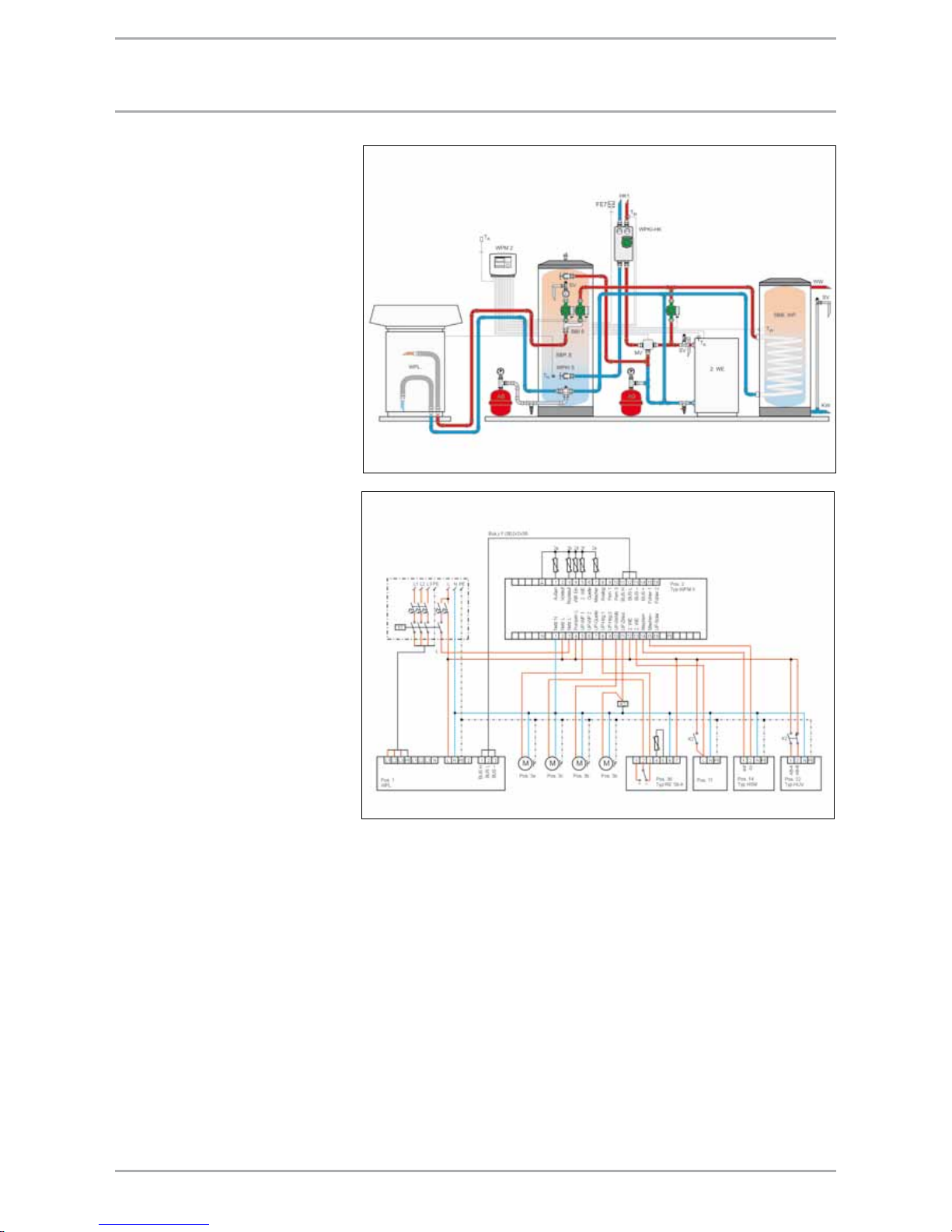
39WWW.STIEBEL-ELTRON.COM
modErnISatIon of oldEr bUIldIngS
Note
When modernising an oil heating
system with a heat pump, the older
oil boiler will frequently be used as
second heat source if the oil tank is
still quite full. This would represent
a dual-mode heat pump system,
making the flue gas inspection for the
oil boiler superfluous. However, in
such cases the dual-mode operation
is just a temporary solution. After
using up the stock of oil, the oil boiler
should be removed and replaced by
the electric booster heater integrated
into the heat pump (mono-energetic
operation). Apart from the spacesaving benefit arising from the
removal of the oil boiler system, the
heating operation would also be
more economical. The running costs
for maintaining the oil combustion
system and the sweeping of the
chimney frequently exceed the energy
costs of the heater rod.
Hydraulic connection
The hydraulic connection is made
as for a new build, if no dual-mode
system with an oil or gas boiler is
envisaged. Dual-mode systems in
which an oil or gas boiler should
be operated for a limited period are
connected hydraulically so that they
can later be dismantled without
having to drain the entire system.
After removal, the heat pump system
will be operated in mono-energetic
mode. The figure to the right shows
the layout of a dual-mode heat pump
system with oil or gas boiler.
Power connection
The power connection of the heat
pump requires two additional meter
spaces in the domestic distribution
board for the heat pump meter and
the ripple control receiver.
In most cases, since the existing
distribution panel lacks the required
space, allow for the panel to be
replaced with a larger one or
supplemented by an additional
distribution panel. This should be
applied for and agreed with your local
power supply utility.
Dual-mode air|water heat pump system
Dual-mode air|water heat pump system
Page 40

40 WWW.STIEBEL-ELTRON.COM
coolIng wItH tHE HEat pUmp SyStEm
Passive cooling
With passive cooling, the low
temperature of the groundwater
or that of the upper earth crust is
transferred to the heating system via
a heat exchanger. The heat pump
compressor will not be started, i.e. the
heat pump remains passive.
Active cooling
During active cooling, the cooling
output of the heat pump (cold side) is
transferred to the heating system. The
heat pump compressor will be started,
i.e. the heat pump becomes active.
Procedure for allowing passive
cooling:
Calculating the cooling load
– to VDI 2078
– in accordance with a standard
form
– in accordance with the m² area
of the living space (factor)
Determining the cooling capacity
of the heat sink
– geothermal probe
– groundwater
Sizing the distribution system
– underfloor heating system
– fan convectors
Heat pump installation
– WPC cool
– WPF
Design information:
The cooling capacity of the heat sink
can be seen in the table on page 41.
For example, two geothermal probes
with a depth of 94 metres can transfer
approx. 7.2 kW to the ground (WPC 13
cool).
The heat transfer by the heat sink
must not exceed the cooling load
of the building. The required room
temperature cannot be achieved if the
cooling load is greater. If necessary,
some rooms must be excluded from
the cooling demand to achieve the
required room temperature in the
other rooms.
Average temperatures underground (°C)
Drilling depth (m) Exposed site Urban area High location
0 9.5 9.5 3.2
25 11.3 12.5 8.0
50 12.0 13.5 8.7
75 12.8 14.5 9.5
100 13.5 15.5 10.2
125 14.3 16.5 11.0
150 15.0 17.5 11.7
175 15.8 18.5 12.5
200 16.5 19.5 13.2
Temperature curve underground
Cooling of buildings
Disabled Enabled
Passive systems Active systems
Utilisation of natural heat sinks
Cool ground / cool night air
Utilisation of storage effects
Utilisation of refrigerators
*+1 °C temperature rise every 33 m
Depth (m)
Page 41

41WWW.STIEBEL-ELTRON.COM
coolIng load calcUlatIon
Cooling load calculation
Calculate the cooling load in
accordance with VDI 2078.
Our cooling load calculation form
or the calculating program assist in
the simplified determination of the
cooling load of a room. Our cooling
load slide rule can also assist in
quickly determining the cooling
load in situ. It can be obtained from
STIEBEL ELTRON sales offices; for
addresses, see the back page of the
technical guide.
Our empirical values too can assist in
achieving a quick sizing:
Factors
Private homes 30 W/m³
Offices 40 W/m³
Sales rooms 50 W/m³
Glass extensions 200 W/m³
Simplified cooling load calculation in
accordance with our calculation form
The cooling load calculation form
enables an easy and quick calculation
of the cooling load of a room. The
calculation is made using the standard
form on page 39. Outside temperature
+32°C at a room temperature +27°C
and constant operation.
Position 1:
Split the window areas in accordance
with the different points of the
compass and multiply them with the
respective values. Insert that point of
the compass into the addition of the
cooling load calculation that results
in the highest value. Use the total of
both values, if windows are positioned
adjacent to two neighbouring points
of the compass, i.e. south-west and
west. Also take horizontal skylights
into consideration (see line "attic
windows"). Consider the stated
reduction factors for equipment
designed to shield against direct
sunlight.
Position 2:
Standard values to VDI 2078 are used
as base for the walls, as the cooling
load is not significantly influenced by
walls.
Position 3:
Floors below unheated cellars or
areas bordering the ground are not
taken into account.
Position 4:
Multiply the ceiling area less any
skylights by the applicable value.
Position 5:
The heat given off by electrical
equipment and lighting is taken
into consideration in line with their
connected load and is multiplied by a
factor of 0.75.
These appliances must only be taken
into consideration if they are switched
on during the cooling operation.
Position 6:
Multiply the number of occupants by
the stated value. The VDI 2067 based
its calculation on the assumption of
occupants at rest or performing light
work.
Position 7:
Apply the outside air proportion of
the appliance in accordance with
manufacturer's details. The cooling
down of the outside air proportion is
taken into account at 5 K.
Cooling load:
Total of the individual cooling loads
for position 1 to 7.
Equipment sizing:
To achieve an internal temperature
of approx. 5 K below the outside
temperature, the equipment cooling
capacity must be equal to or greater
than the calculated cooling load.
Basis:
Apart from the influences stated
above, this calculation process also
takes into account the storage capacity
of the room. This is based on the
variables in VDI 2078.
Calculation room 1
(see calculation sheet)
The cooling load is calculated in
accordance with the following details:
Room size 5.0 m wide, 5.0 m long,
3.0m high, window size 4.0 m²
towards the west
Window with external blinds
Number of occupants: 2
Computer 500 W connected load
Flat roof with 5 cm insulation; lightly
constructed external walls.
Result:
The calculated cooling load of room 1
is 2.2 kW.
Page 42

42 WWW.STIEBEL-ELTRON.COM
Cooling load calculation form
For estimating the cooling load of a room with reference to the VDI 2078
Address: Type of room:
Name: Size of room:
Street: Length Width Height Surface
Volume
Town: 5.0 m 5.0 m 3.0 m 25.0 m² 75.0 m³
1. Insolation through
windows and external doors
Exposed window
Reduction factor, solar protection
Window
area
m²
Cooling load,
windows,
watt
single
glazed
W/m²
double
glazed
W/m²
thermo
glazed
W/m²
internal
blinds
awnings
external
blinds
North 65 60 35
x 0.7 x 0.3 x 0.15
Northeast 80 70 40
East 310 280 155
Southeast 270 240 135
South 350 300 165
Southwest 310 280 155
West 320 290 160 4.0 174
Northwest 250 240 135
Attic window 500 380 220
Only use the maximum value for different points of the compass. 174
2. Walls less window and door openings that have already been taken into account.
Cooling load
W/m²
Wall area
m²
Cooling
load, wall
watt
External walls 10 26.0 260
Internal walls 10 15.0 150
Total 410
3. Floor towards non-air conditioned areas
Cooling load
W/m²
Floor area
m²
Cooling
load, floor
watt
Total 10 25.0 250
4. Ceiling less roof windows and fanlights
that have already been recorded
Flat roof Pitched roof
Ceiling
towards
non-air
conditioned
rooms W/m²
Ceiling area
m²
Cooling
load, ceiling
watt
not
insulated
W/m²
insulated
W/m²
not
insulated
W/m²
insulated
W/m²
Total
60 30 50 25 10 25.0 750
5. Electrical appliances that are operated at the time of cooling
Connected
load
watt
Factor
Cooling load,
appliances
watt
Lighting
Computer with monitor and printer 500 x 0.75 375
Total 375
6. Heat given off by occupants that are at rest or perform only light work
Cooling load
W/person
Occupants
number
Occupants
watt
Total 120 2 240
7. Outside air for air conditioning appliance with a proportion of outside air
Cooling load
W/m²
Air volumem³Ventilation air
watt
Total 10
Total cooling load of the room in watts
The estimated cooling load results in a temperature reduction of approx. 5 °C
2199
coolIng load calcUlatIon
Page 43

43WWW.STIEBEL-ELTRON.COM
HEat SInkS for coolIng opEratIon
Cooling with a geothermal probe
Passive cooling with geothermal
probes utilises the constant
temperature of the ground at greater
depths. In standard houses, the
cooling capacity is adequate for the
few days of the year, when cooling is
desirable. With high cooling loads,
the temperature underground can rise
gradually. This would result in a slight
reduction of the cooling effect via
the underfloor heating system or fan
convectors.
Note: The geothermal probe can be
larger if greater cooling loads are
required. The probe for the cooling
operation should not be longer than
100 metres.
Cooling with groundwater
The groundwater temperature never
rises above +14°C, even in summer.
That makes it an ideal choice for
passive cooling. The low temperature
is transferred to the heating water via
a heat exchanger, thereby utilising
the underfloor heating system or
fan convectors to cool the building.
With this kind of operation, the
temperature of the groundwater
returned underground must not
exceed 20 °C. A water analysis should
verify that the water is compatible
with the heat exchanger material.
Cooling with geothermal collectors
Geothermal collectors are only
suitable for passive cooling to a
limited extent. The temperature
near the surface of the ground is
substantially dependent on the
outside temperature. With an
additional heat transfer over time, the
temperature would rise higher than
+15°C, making cooling impossible.
Main layout geothermal probe heat pump system
Main layout groundwater heat pump system
Main layout geothermal collector heat pump system
Page 44

44 WWW.STIEBEL-ELTRON.COM
Cooling with a geothermal probe
Geothermal probes are sized in accordance with the heat pump heating output.
The heat that must be transferred to the ground during passive cooling is approx. 70% of the extraction rate (approx.
35 W/m probe length).
Example:
Heat pump WPF/C 10 cool
Required geothermal probe 2 pce. @ 70 metre length
Extraction rate approx. 55 W per metre equates to approx. 7.7 kW.
The transfer to the ground amounts to approx. 5.4 kW.
Cooling with groundwater
The amount of groundwater that can be utilised to remove heat is determined in accordance with the amount of
groundwater required by the heat pump.
The temperature differential between the groundwater and the cooling water is approx. 5 K.
Example:
Heat pump WPW 13
Required volume of groundwater 2.6 m³/h
The groundwater can remove approx. 15.1 kW.
Sizing table geothermal probe DN 25
for normal solid rock, extraction capacity 55 W/m (average value)
Heat pump type
Source temperature 0°C
Flow temperature 35°C
Geothermal probe
32 x 2.9
Number
Geothermal probe
32 x 2.9
Depth
Extraction,
heating mode
Transfer, cooling
mode
Heating output Cooling capacity
WPF/C 5 cool 5.8 kW 4.5 kW 1 pce. 82 m 4.5 kW 3.2 kW
WPF/C 7 cool 7.8 kW 6.0 kW 1 pce. 109 m 6.0 kW 4.2 kW
WPF/C 10 cool 9.9 kW 7.7 kW 2 pce. 70 m 7.7 kW 5.4 kW
WPF/C 13 cool 13.4 kW 10.3 kW 2 pce. 94 m 10.3 kW 7.2 kW
WPF 16 cool 16.1 kW 12.5 kW 3 pce. 84 m 13.8 kW 9.6 kW
Sizing table groundwater
Groundwater temperature approx. 15 °C (average value during cooling operation)
Heat pump type
Source temperature 10°C
Flow temperature 35°C
Groundwater amount Transfer, cooling mode
Heating output Cooling capacity
WPW 7 7.2 kW 5.9 kW 1.5 m³/h 8.7 kW
WPW 10 10.0 kW 8.2 kW 2.1 m³/h 12.2 kW
WPW 13 12.5 kW 10.2 kW 2.6 m³/h 15.1 kW
WPW 18 17.1 kW 14.1 kW 3.4 m³/h 19.7 kW
WPW 22 M 21.7 kW 18.2 kW 4.4 m³/h 25.5 kW
coolIng capacIty
Page 45
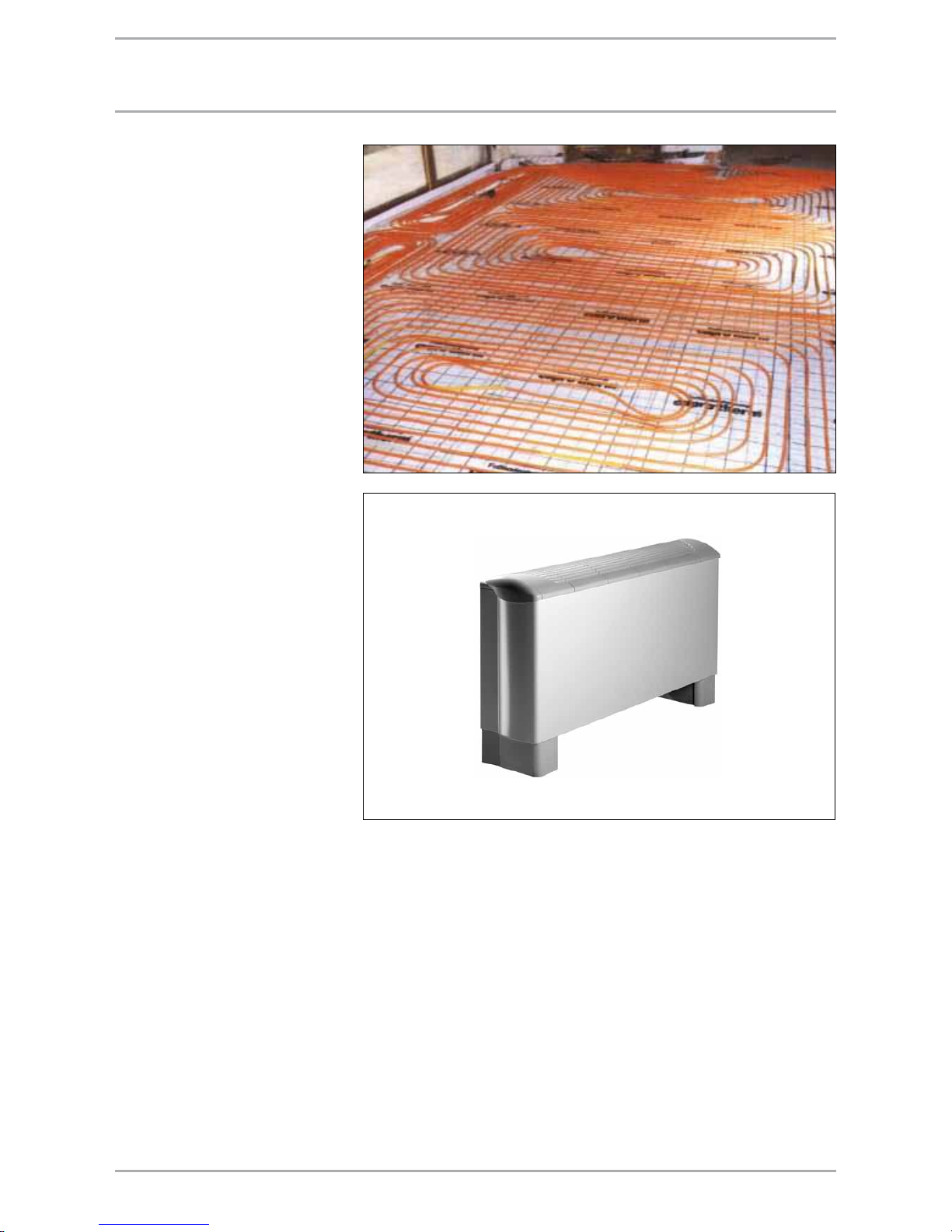
45WWW.STIEBEL-ELTRON.COM
dIStrIbUtIon SyStEm for coolIng opEratIon
Distribution systems
Subject to the type of installed coolant
distribution system, the cooling water
temperatures can be between +8°C
and +16°C. To prevent condensation,
the cooling water temperature in
underfloor heating systems lies
above the dew point. The dew point
temperature is subject to the air
temperature and the relative humidity.
For that reason, any global statement
of the possible average cooling load of
these systems can only be viewed as a
rough estimate.
For fan convectors, the cooling water
temperatures can be reduced below
the dew point, and sensible as well
as latent heat can be extracted from
the room air through the condensate
removal. In addition, cooling ceilings
or wall heating systems are suitable
for passive cooling with ground source
heat pumps.
Underfloor cooling
With only little additional control
effort and equipment, the underfloor
heating system can also be used for
cooling during the warmer season.
The application is limited by DIN 1946
T2; consequently an average cooling
load of approx. 20 to 25 W/m² results.
The manufacturer must approve the
suitability of the floor structure for
cooling, particular that of the installed
screed. Passive cooling requires
changeover zone valves with 230 V
control voltage.
Fan convectors/cassettes
The cooling load of a fan convector/
cassette is subject to the size, the
air flow rate and the cooling water
temperature. Where sizing takes
the requirements of DIN 1946 into
account, specific cooling loads of 30
to 60 W/m² heat exchanger surface
are achieved. The common equipment
sizing for average fan stages offers
users the option of regulating quickly,
even when heat loads fluctuate
severely (high fan stage).
Fan convectors
Source: Rehau
26_0 3_01_0389
26_0 3_01_0390
Page 46

46 WWW.STIEBEL-ELTRON.COM
coolIng capacIty, UndErfloor HEatIng SyStEm
Cooling capacity, underfloor heating systems
Floor covering Tiles Carpet
Installation spacing cm 5 10 15 20 30 5 10 15 20 30
Room temperature °C 27 27 27 27 27 27 27 27 27 27
Flow temperature °C 15 15 15 15 15 15 15 15 15 15
Return temperature °C 20 20 20 20 20 20 20 20 20 20
Cooling capacity W/m² 52 45 39 34 26 33 29 26 24 19
Cooling capacity, underfloor heating systems
Floor covering Tiles Carpet
Installation spacing cm 5 10 15 20 30 5 10 15 20 30
Room temperature °C 23 23 23 23 23 23 23 23 23 23
Flow temperature °C 15 15 15 15 15 15 15 15 15 15
Return temperature °C 20 20 20 20 20 20 20 20 20 20
Cooling capacity W/m² 26 22 19 17 13 16 14 13 12 11
Underfloor heating system heating output
Floor covering Tiles Carpet
Installation spacing cm 5 10 15 20 30 5 10 15 20 30
Room temperature °C 20 20 20 20 20 20 20 20 20 20
Flow temperature °C 35 35 35 35 35 35 35 35 35 35
Return temperature °C 30 30 30 30 30 30 30 30 30 30
Cooling capacity W/m² 65 55 50 45 30 40 37 32 28 24
With underfloor cooling, the cooling
load is not only subject to the heat
sink but also to the cooling capacity
of the underfloor heating system. For
example, an underfloor heating system
with tiled cover and a spacing between
pipes of 10 cm has a specific cooling
capacity of 22 W/m². The required room
temperature cannot be achieved if the
cooling load of the room is greater than
the cooling capacity of the underfloor
heating system. In such cases, either
install fan convectors or limit the use to
tempering the room.
Comfort
A person's capacities suffer severely
at room temperatures that are too
low or too high. Comfortable room
temperatures are therefore essential
for our wellbeing. In most cases,
cooling systems can ensure very good
room comfort with only little energy
expenditure. The energy exchange
between a person and the cooling
area predominantly takes the form
of radiation. Underfloor cooling
therefore provides excellent prerequisites for a comfortable ambient
climate.
Comfort zone (Leusden & Freymark)
Room air temperature TL (°C)
Relative humidity (%)
uncomfortably humid
comfortable
just comfortable
uncomfortably dry
Page 47

47WWW.STIEBEL-ELTRON.COM
Equipment description
Hydrima stand-alone appliance for
cooling and heating; for floorstanding
and wall mounted installation.
Internal appliance in an attractive
design, three-stage fan operation,
operating mode selector, dirt filter
and hard-wired remote control.
Window contact:
A N/C contact can be connected via
terminal strip WIN, terminals 5 and
6. With the contact open, the valve is
closed and the fan is switched OFF.
Heating operation:
Heat is transferred to the ambient
air via the heat exchanger. The
multi-stage fan constantly changes
the ambient air, which is cleaned
in the process by the integral filter.
The air changes ensure a pleasant
temperature distribution in the room.
Cooling mode:
Heat is withdrawn from the room by
the heat exchanger and transferred
to the geothermal probe via the
pipework system. In the process,
condensate can be created at the
heat exchanger, subject to certain
operating conditions; this must be
drained off via the condensate drain.
coolIng capacIty, fan convEctorS
Type ACTH 20 ACTH 40 ACTH 50
Part no. standard unit 18 98 20 18 98 21 18 98 22
Cooling operation output details
Fan stage small medium high small medium high small medium high
Cooling water temperature °C 15/20 15/20 15/20 15/20 15/20 15/20 15/20 15/20 15/20
Cooling capacity at 23°C room temp. W 285 367 532 532 588 662 680 799 969
Cooling capacity at 25°C room temp. W 373 510 577 764 865 1036 940 1168 1505
Cooling capacity at 27°C room temp. W 459 647 747 974 1137 1402 1180 1495 2037
Cooling capacity at 29°C room temp. W 609 828 968 1291 1370 1747 1583 1947 2551
Cooling capacity at 31°C room temp. W 833 1121 1289 1786 2054 2464 2186 2712 3564
Heating operation output details
Fan stage small medium high small medium high small medium high
Heating water temperature °C 50/40 50/40 50/40 50/40 50/40 50/40 50/40 50/40 50/40
Heating output at 15°C room temp. W 1600 2185 2780 3255 4570 5065 4955 6270 7250
Heating output at 18°C room temp. W 1475 2015 2565 3000 4215 4675 4570 5780 6685
Heating output at 20°C room temp. W 1405 1915 2440 2855 4015 4450 4350 5500 6365
Heating output at 22°C room temp. W 1315 1795 2285 2675 3760 4165 4075 5155 5960
Heating output at 24°C room temp. W 1230 1675 2130 2495 3505 3885 3800 4805 5560
Fan convector installation
Fan convector power supply
1 Return connection
2 Flow connection
3 Condensate drain
4 Servomotor
5 Drain valve
6 Air vent valve
7 Air blow-off grille
8 User interface
9 Air entry
MIU Interface extension
UNOC Time switch contact input
WIN Window contact input
RC User interface plug-in strip
J1 Plug and jumper
ST Plug-in contact 230 V
Power supply and
jumper allocation, see
installation instructions ACTH
Page 48

48 WWW.STIEBEL-ELTRON.COM
Equipment description
Hydrima cassette cooling and
heating appliance for installation in
suspended ceilings. Internal appliance
in an attractive design, three-stage fan
operation, operating mode selector,
dirt filter and hard-wired remote
control.
Heating operation:
Heat is transferred to the ambient
air via the heat exchanger. The
multi-stage fan constantly changes
the ambient air, which is cleaned
in the process by the integral filter.
The air changes ensure a pleasant
temperature distribution in the room.
Cooling mode:
Heat is withdrawn from the room by
the heat exchanger and transferred
to the geothermal probe via the
pipework system. In the process,
condensate can be created at the
heat exchanger, subject to certain
operating conditions; this must be
drained off via the condensate drain.
coolIng capacIty, caSSEttES
Type ACKH 10 ACKH 12 ACKH 18
Part no. standard unit 22 34 41 22 34 42 22 34 43
Cooling operation output details
Fan stage small medium high small medium high small medium high
Cooling water temperature °C 15/20 15/20 15/20 15/20 15/20 15/20 15/20 15/20 15/20
Cooling capacity at 23°C room temp. W 413 435 550 656 691 874 868 915 1158
Cooling capacity at 25°C room temp. W 563 593 750 894 942 1192 1184 1247 1579
Cooling capacity at 27°C room temp. W 713 751 950 1133 1193 1510 1500 1580 2000
Cooling capacity at 29°C room temp. W 863 909 1115 1371 1444 1828 1816 1913 2421
Cooling capacity at 31°C room temp. W 1013 1067 1350 1609 1695 2146 2132 2245 2842
Heating operation output details
Fan stage small medium high small medium high small medium high
Heating water temperature °C 50/40 50/40 50/40 50/40 50/40 50/40 50/40 50/40 50/40
Heating output at 15°C room temp. W 2505 2689 3684 3411 3662 5016 4325 4643 6360
Heating output at 18°C room temp. W 2255 2420 3316 3070 3296 4514 3892 4179 5724
Heating output at 20°C room temp. W 2088 2241 3070 2842 3051 4180 3604 3869 5300
Heating output at 22°C room temp. W 1921 2062 2824 2615 2807 3846 3316 3559 4876
Heating output at 24°C room temp. W 1754 1883 2579 2388 2563 3511 3027 3250 4452
Cassette installation
A T bracket, suspended ceiling
B Suspended ceiling
C Heat exchanger
D Fan
E Air grille
F Cable entry, power supply
G Condensate connection 15 mm
H Flow connection
I Return connection
J Fresh air supply connection
K Ancillary room cooling connection
ACKH 10 ACKH 12 ACHK 18
X 39 mm 39 mm 50 mm
Y 120 mm 113 mm 95 mm
Z 118 mm 120 mm 102 mm
G 1/2" G 1/2" G 3/4"
Dimensions in mm
Page 49

49WWW.STIEBEL-ELTRON.COM
paSSIvE coolIng wItH tHE wpc cool HEat pUmp
Passive cooling with the WPC cool
heat pump
Installation information:
Use only pipes and fittings made from
corrosion-resistant materials.
Condensate is prevented reliably
through the integral dew point
monitor in the lead room. If sensible
areas in the building are crossed,
where other dew point temperatures
must be expected or where the
temperature falls below the dew point
temperature (fan convectors), insulate
all lines with diffusion-proof material.
WPC cool mono-mode with passive cooling (heating mode)
WPC cool mono-mode with passive cooling (cooling mode)
WPC cool mono-mode with passive cooling
Minimum circulation volume
on the heating side 20% of
the nominal flow rate of the
heat pump
Minimum circulation volume
on the heating side 20% of
the nominal flow rate of the
heat pump
Page 50

50 WWW.STIEBEL-ELTRON.COM
paSSIvE coolIng wItH tHE wpf..E HEat pUmp
With brine | water heat pumps,
the heat source can also be used
for cooling purposes, i.e. as a heat
sink. An area heating system or fan
convectors is/are required for this
function. An integral control unit
in the heating system prevents the
temperature falling below the dew
point. When selecting the heating
circuit pump, ensure that only cast
pumps (condensate forming between
the casing and the stator) or rotary
pumps are used.
WPF..E mono-mode with passive cooling (cooling mode)
WPF E mono-mode with passive cooling
Page 51

51WWW.STIEBEL-ELTRON.COM
paSSIvE coolIng wItH tHE wpf HEat pUmp
WPF mono-mode with passive cooling (heating mode)
WPF mono-mode with passive cooling (heating mode)
WPF mono-mode with passive cooling (heating mode)
Passive cooling with the heat pump
WPF.
With brine | water or water | water
heat pumps, the heat source can
also be used for cooling purposes,
i.e. as a heat sink. An area heating
system is required for this function.
A suitable controller in the heating
system prevents the temperature
falling below the dew point. A heat
exchanger is required to avoid the
need for filling the entire heating
system with brine. When selecting the
pump, ensure that only cast pumps
(condensate forming between the
casing and the stator) or rotary pumps
are used.
Page 52

52 WWW.STIEBEL-ELTRON.COM
actIvE coolIng wItH tHE wpc HEat pUmp
Active cooling with the WPC heat
pump
Active cooling is unsuitable as the
only source of cooling in underfloor
heating systems. This requires
additional fan convectors. Use
only pipes and fittings made from
corrosion-resistant materials. Insulate
all lines entering the house in a
vapour diffusion-proof manner to
prevent the formation of condensate.
WPC mono-mode with active cooling (heating mode)
WPC mono-mode with active cooling (cooling mode)
WPC mono-mode with active cooling
Page 53
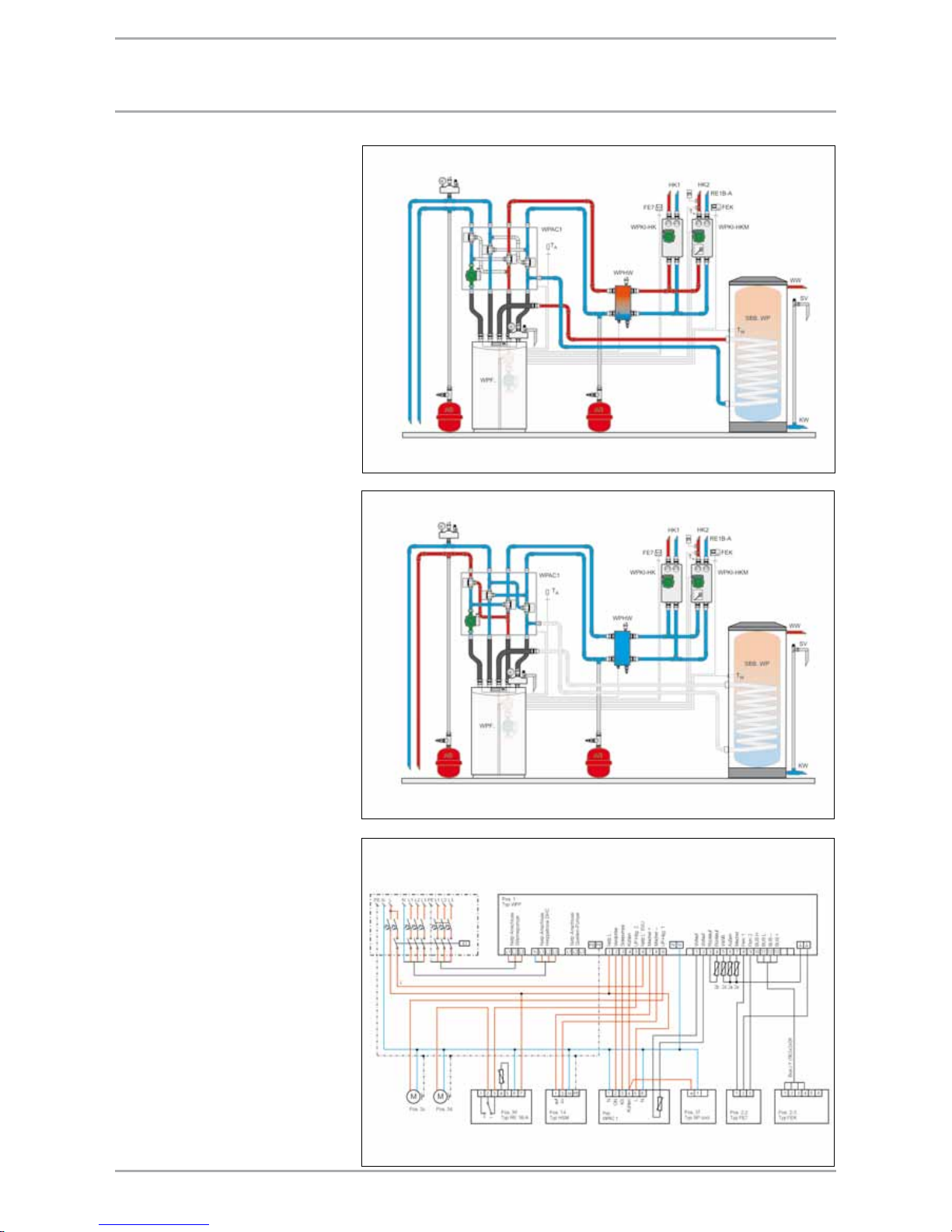
53WWW.STIEBEL-ELTRON.COM
actIvE coolIng wItH tHE wpf HEat pUmp
Active cooling with the WPF heat
pump
Brine | water heat pumps WPF, in
conjunction with the cooling module
WPAC1, can be used for active
cooling. Active cooling is unsuitable
as the only source of cooling in
underfloor heating systems. This
requires additional fan convectors.
Use only pipes and fittings made
from corrosion-resistant materials.
Insulate all lines entering the house
in a vapour diffusion-proof manner to
prevent the formation of condensate.
WPF mono-mode with active cooling (heating mode)
WPF mono-mode with active cooling (cooling mode)
WPF mono-mode with active cooling (cooling mode)
Page 54

54 WWW.STIEBEL-ELTRON.COM
actIvE coolIng wItH tHE wpl HEat pUmp
Active cooling with the WPL heat
pump
Air | water heat pumps can also
be used for cooling buildings. The
heating heat pump should be sized
for heating operation, i.e. for use
in winter. Matching of the cooling
capacity of the heat pump system
to the cooling load of the building
opens up the possibility of cooling in
summer. The sizing of the distribution
system is crucial for the transfer of
thermal loads. Underfloor heating
systems are only suitable for the
transfer of high loads to a limited
degree, e.g. in conjunction with active
cooling of buildings, as the transfer
rate is low and frequent cycling of
the heat pump cannot be prevented.
A combination with fan convectors is
recommended.
WPL mono-energetic with active cooling (heating mode)
WPL mono-energetic with active cooling
WPL mono-energetic with active cooling (heating mode)
Page 55

55WWW.STIEBEL-ELTRON.COM
Note the following when installing the
appliances outside:
Ensure short runs between heat
pump and building (heat losses)
Check noise pollution (avoid
"noise reflecting" environments);
if necessary factor in on-site
deflectors
Provide foundations (e.g. timbers,
blocks, concrete slabs)
Install connecting lines in
thermally insulated conduits
underground (min. Ø 100 mm)
Provide wall outlets for pipework
(min. 150 x 150 mm)
Provide condensate drain pipes
(pipework, free from the risk of
frost or underground soak away)
Subject to installation type, check
whether planning permission is
required
Ensure a free air flow
Avoid thermal short-circuits
Provide space for the installation
(whether external or internal)
Connect heat pump to the flow
and return using flexible pipes
Protect the heating circuit against
frost
Provide a power supply and wiring
aIr | watEr HEat pUmp - ExtErnal InStallatIon
Page 56
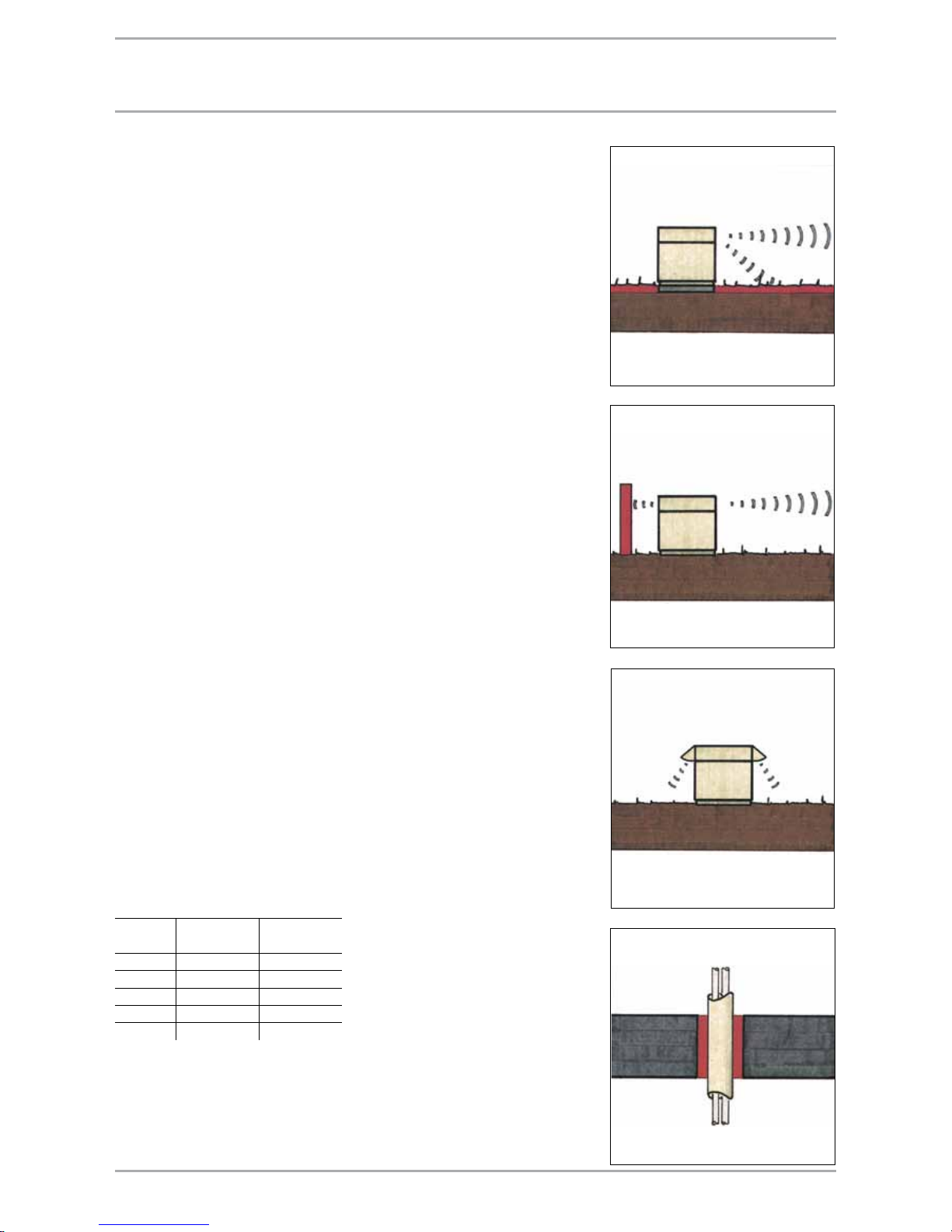
56 WWW.STIEBEL-ELTRON.COM
Air routing
When installing air | water heat
pumps externally, there are generally
no problems associated with
routing the air. However, prevent
the discharge of cold air towards
neighbouring properties (patios,
balconies). Also prevent air being
directed immediately at house or
garage walls. Pay particular attention
to noise pollution. Prior to installation,
consider the sound propagation,
whether towards neighbouring
properties or towards your own home.
Never install the heat pump
immediately adjacent to living
rooms or bedrooms. Insulate pipes
through walls and ceilings against
structure-borne noise transmission.
The heat pumps are characterised
by their particularly quiet operation.
Nevertheless, incorrect installation
can, under unfavourable conditions,
lead to unwanted high noise levels.
Observe the following for external
installations:
Plants can reduce reflections that
may occur, for example when
installing the equipment between
two walls.
Avoid installation on large floor
areas off which sound can bounce.
Installation between two closed
walls as well as in corners and
corners can lead to higher noise
levels, as these surfaces can act
as sound reflectors and should
therefore be avoided.
Reductions in noise levels can
be achieved through on-site
deflectors.
Sound pressure level
at 5 m
distance
at 10 m
distance
WPL 10 43 dB(A) 37 dB(A)
WPL 13 43 dB(A) 37 dB(A)
WPL 18 43 dB(A) 37 dB(A)
WPL 23 43 dB(A) 37 dB(A)
WPL 33 43 dB(A) 37 dB(A)
SoUnd EmISSIonS
Acoustic measures
Lawn areas and shrubs can contribute
to the reduction of noise. Avoid
installation on hard floor areas.
Large floor areas of which sound can
bounce can act as reflectors and can
raise sound levels by up to 3 dB(A)
compared with an installation on
insulated floors.
Direct noise propagation when
installing heat pumps outside can be
impeded by on-site deflectors. Noise
levels can be reduced by walls, fences,
palisades etc.
A noise reduction of 2 dB(A) can be
achieved with the WPL 13/18/23/33 by
using a duct silencer.
Part no. 18 53 25 (WPL 13/18/23)
Part no. 18 53 70 (WPL 33)
As for all heating systems, the transfer
of structure-borne noise through
heating pipes to brickwork and
radiators should be prevented. Heat
pumps should therefore be connected
to the heat distribution system via
flexible hoses, flexible connections of
pipework to walls and ceilings and
flexible routing of pipework through
walls and floors.
Page 57

57WWW.STIEBEL-ELTRON.COM
SoUnd EmISSIonS
Acoustic emissions
Noise, a sound or a tone are all
described as sound. Sound spreads by
the transfer of kinetic energy from one
molecule to another.
A sound carrier medium is always
required for sound transmission (air,
water, iron etc.). From a physical
aspect, sound takes the form of a
wave that expands in circular form.
The movement of sound waves can be
compared to that of water waves.
Reflection
Where sound waves hit a wall the
waves are reflected at the same angle
as that of the impact.
Absorption
If sound waves impact on a soft,
porous wall, some of the sound
energy is converted to frictional heat.
Law of Distance
The sound pressure level is reduced by
approx. 6 dB(A) if distance L doubles
in length.
Law of Distance using the WPL 10 as
an example
Sound power level
LwA = 65 dB(A)
Sound pressure level
LpA1 (5 m distance) = 43 dB(A)
Sound pressure level
LpA2 (10 m distance) = 37 dB(A)
Sound power level
The sound power level describes
the sound emissions from a source
or sound. It is determined using the
sound pressure level, relative to the
envelope area of the source of sound,
i.e. the so-called envelope method.
Sound pressure level
The sound pressure level, measured in
the ambience, is subject to the sound
power level, the distance at which the
level is measured and the structural
surroundings.
Human perception
If a sound is perceived to be twice as
loud, this corresponds to a rise by 10
dB(A).
Two sources of sound of the same volume
correspond to a rise of 3 to 6 dB(A).
Sound propagation
Sound propagation
Distance
from the
source of
sound to the
perceiving
person
Reduced sound pressure level from the sound power level subject to the
distance and the installation conditions
1 m 8.0 dB(A) 5.0 dB(A) 2.0 dB(A)
2 m 14.0 dB(A) 11.0 dB(A) 8.0 dB(A)
3 m 17.0 dB(A) 15.0 dB(A) 12.0 dB(A)
4 m 20.0 dB(A) 17.0 dB(A) 14.0 dB(A)
5 m 22.0 dB(A) 19.0 dB(A) 16.0 dB(A)
7 m 25.0 dB(A) 22.0 dB(A) 19.0 dB(A)
10 m 28.0 dB(A) 25.0 dB(A) 22.0 dB(A)
15 m 32.0 dB(A) 29.0 dB(A) 26.0 dB(A)
20 m 34.0 dB(A) 31.0 dB(A) 28.0 dB(A)
Law of Distance
The sound pressure level is reduced by
approx. 6 dB(A) if distance L doubles in
length.
Law of Distance using the WPL 10 as an example
Sound power level L
W
A = 65 dB(A)
Sound pressure level LPA1 (5 m distance)
= 43 dB(A)
Sound pressure level LPA2 (10m distance)
= 37 dB(A)
Page 58

58 WWW.STIEBEL-ELTRON.COM
Condensate drain
The condensate drain hose must be
routed with a slope downwards or to
the side out of the heat pump. When
installing the heat pump outside,
route the condensate to an existing
drain or into a coarse gravel soak
away. For this, ensure an installation
that is free from the risk of frost.
conDensate connection
Concrete slab, approx. 10 cm
Gravel layer, approx. 30 cm
Condensate drain
approx. 120 cm
Condensate drain
Page 59
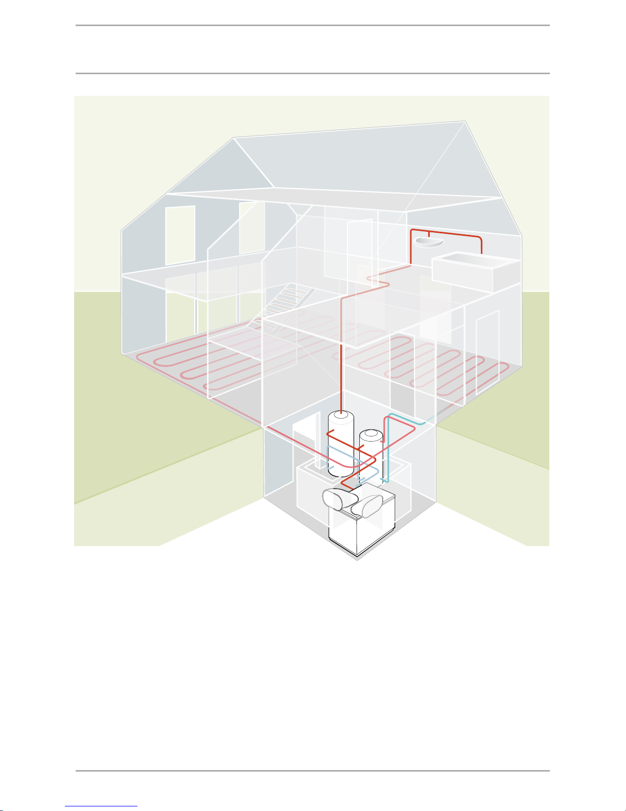
59WWW.STIEBEL-ELTRON.COM
Note the following when installing the
appliances inside:
Observe the particular
requirements of the installation
location
Maintain wall clearances (service)
Requirements of the installation
position
Provide a condensate drain from
the evaporator
"Thermal short-circuits" when
arranging the apertures
Connect the heating system flow
and return lines with flexible
hoses to the heat pump
Protect air inlet and discharge
apertures and the ventilation set
aperture against ingress of leaves
and snow
If required, clad walls in the
installation location with antireflection, sound absorbing
material
Consider the power connection
Carefully insulate brickwork
around the inlet and discharge
apertures
Insulate the wall outlets
aIr | watEr HEat pUmpS - IntErnal InStallatIon
Page 60

60 WWW.STIEBEL-ELTRON.COM
aIr roUtIng
Air routing
For internal installations, connect the
air side with flexible air hoses or via
air ducts and flexible connections
routed to the outdoors. Observe
previous instructions regarding
acoustic emissions. Limit the velocity
at the air inlet and discharge to a
maximum of 2 m/s, relative to the
free cross-section of the air grille
(noise development). Always prevent
a short-circuit between the air inlet
and discharge. It would be practical to
route the ventilation air supply across
a corner or a cross. If the inlet and
discharge apertures are at the same
level, ensure a minimum clearance
of 3 m. Provide a dividing wall or
shrubs, if necessary. The weather or
bird protection grilles should be easily
removable for cleaning purposes.
Acoustic emissions
Never install the heat pump
immediately below or adjacent to
bedrooms. For hard floor areas (e.g.
tiles), we recommend placing a
rubber mat below the appliance. Good
sound insulation can be achieved
by using a concrete plinth with a
rubber mat underneath the appliance.
Insulate pipes through walls and
ceilings against structure-borne
noise transmission. The compact heat
pumps series WPL are characterised
by a particularly quiet operation.
Nevertheless, incorrect installation
can, under unfavourable conditions,
lead to unwanted high noise levels.
Cellar – in a corner
The example shows the installation
of a compact heat pump in a cellar.
Routing the air via different sides of
the building effectively prevents shortcircuits between discharge and inlet
air. The inlet and discharge grilles
should be sized so that discharge
free ventilation cross-section is large
enough.
Cellar – separate ducts
When installing a compact heat pump
in the cellar, connection of air ducts to
two cellar light wells on the same side
of the building is possible, subject to
the distance between the light wells
being sufficient to prevent a thermal
short-circuit. The inlet and discharge
ducts are protected by a cover against
leaves and snowfall.
Cellar – common duct
When installing a compact heat pump
in the cellar, connection of air ducts to
a common cellar light well is possible,
subject to thermal short-circuits being
reliably prevented. In this example the
inlet flow is diverted. A dividing wall
between the air inlet and discharge
inside the light well and a deflector
outside the light well prevent a
thermal short-circuit to the greatest
extent.
Note
Observe particularly the following
points for this installation type:
avoid thermal short-circuits
provide a suitable condensate
drain
provide a sufficiently large
free cross-section for inlet and
discharge grilles
Page 61

61WWW.STIEBEL-ELTRON.COM
Condensate drain
Use a ¾" hose as condensate
drain that should be pushed onto
the defrost pan connector in the
heat pump. The condensate drain
hose must be routed with a slope
downwards or to the side out of the
heat pump. For internal installations
route the defrost water into a drain.
When using a condensate pump PK 10
for draining the condensate, install
the heat pump approx. 100 mm
higher (foundation acc. to illustration)
or arrange the installation of the
condensate pump approx. 100 mm
lower.
conDensate connection
Page 62

62 WWW.STIEBEL-ELTRON.COM
cHEcklISt
Design/engineering and installation of air|water heat pumps
What is the purpose of the heat pump?
What heat source supplies the heat pump?
How are the heating surfaces designed? Low temperature heating systems are recommended.
What is the required heating output? Calculate the heat demand.
Obtain permission from your power supply utility [if required].
Determine the operating mode of the heat pump according to the heating system.
How can the heat pump be integrated easily into the heating pipework?
Should DHW be heated by the heating heat pump?
How do I make the power connection?
Observe general requirements and guidelines.
Observe conditions on site.
Air|water heat pumps - external installation
Where can the heat pump be located? Provide foundations.
Observe the air routing. The air discharge direction should be, where practicable, in line with the main wind
direction.
Ensure that neighbouring properties are not disturbed by noise.
Maintain minimum clearances to the periphery, if necessary check whether planning permission is required.
Ensure short line runs.
Can the condensate be routed free from the risk of frost and with a natural slope?
Air|water heat pumps - internal installation
Is a suitable location for the installation of the heat pump available?
Choose an installation location where the appliance has sufficient room to allow operation and maintenance.
Provide foundations for the installation of the heat pump.
Are inlet and discharge apertures available? Avoid thermal short-circuits.
Can the air hoses be installed easily?
Is the total length of the pipework less than 8 m?
Can the condensate be routed with a natural slope or does a condensate pump have to be installed?
Insulate wall outlets
Page 63

63WWW.STIEBEL-ELTRON.COM
aIr|watEr HEat pUmpS
Compact convenience
Design and installation are completely
problem-free with air | water heat
pumps from STIEBEL ELTRON. The
practical compact design houses all
components and safety equipment
together inside a single enclosure.
That reduces the overall volume and
saves valuable space. The air|water
heat pump uses the outside air down
to a temperature of –20°C as a heat
source. Between –5°C and –20°C, a
small electric booster heater switches
itself ON, subject to demand. In its
different versions, this produces
sufficient heat for small to large
houses with a living space of up to
500 m².
WPL - types and applications
Classic Inverter
Application range WPL..E WPL..E cool WPL 10 WPL 33 WPL HT WPL .. AZ WPL 5 N
New build
Older building <= 55 °C
Older building <= 70 °C
DHW temperature >60 °C without electric booster heater
Cascade
External installation
Internal installation
Solar option
Cooling
Installation in tight spaces
Heating only
Swimming pool
Dual-mode operation
COP A2/W35 3.7
(1)
3.7
(1)
3.3 3.3/2.9
(2)
3.2 3.0 3.4
(3)
Sound power level, outside (db(A)) 65 65 65 65 58/62
(4)
< 70
(5)
55
DHW cylinder variable / fixed from 300 from 300 from 300 from 300 from 300 200 200
Radiators may be used without buffer
Area heating may be used without buffer
Easy installation
(1)
relative to the WPL 18 E/cool
(2)
COP with single compressor / with 2 compressors
3)
With reference to VDI 4650 with 35% DHW proportion
(4)
Internal/external
(5)
WPL 20 AZ (A7/W45)
26_0 3_01_0402
Page 64

64 WWW.STIEBEL-ELTRON.COM
aIr | watEr HEat pUmp wpl 5 n
Safety and qualityAt a glance
For fully automatic heating
water heating up to +70 °C flow
temperature
Suitable for underfloor and
radiator heating systems; low
temperature heating systems
are preferred, as these achieve a
higher coefficient of performance
Extracts energy from the outside
air, right down to -20 °C outside
temperature
Comprises all components
required for its function and
safety
Central control of the heating
system and safety functions
through the heat pump manager
(essential accessory)
Corrosion-protected, external
casing panels made from zincplated sheet steel plus stove
enamelled finish; internal airways
made from corrosion-resistant
aluminium sheet
Compact design, therefore modest
space requirement
Contains non-combustible natural
CO2 safety refrigerant R744
Output matching through two
inverter compressors
Extremely quiet operation
Function
Heat is extracted from the outside air
at temperatures ranging from +35°C
to –20 °C by the heat exchanger
on the air side (evaporator) of the
external unit. Heating water is
heated to flow temperature levels
in the heat exchanger on the water
side (condenser) by this extracted
heat and additional heat from
the electrical power used by the
compressor. At air temperatures
below approx. +7 °C, the humidity
in the air precipitates as hoarfrost
on the evaporator fins. Any hoarfrost
is automatically defrosted. Water
created from this defrosting collects
in the defrost pan below the external
unit and is drained off.
Appliance description
Air | water heat pump system with
little space requirement, comprising
a heat pump for external installation
and a cylinder module for internal
installation. The heat pump is
suitable for wall mounting (wall
mounting bracket accessory 222263)
and is designed to be electrically
and hydraulically connected with
the cylinder module. The cylinder
module consists of a 200 litre
enamelled DHW cylinder and the
integral heat pump manager. The
required circulation pumps for
heating and DHW as well as the
booster heater for mono-energetic
mode are built in as standard. The
heat pump is filled with the natural
refrigerant CO2. The heat pump is
controlled via a BUS cable.
Page 65

65WWW.STIEBEL-ELTRON.COM
aIr | watEr HEat pUmp wpl 5 n
Type WPL 5 N
Part no. complete appliance 22 11 43
Part no. hydraulic module 22 11 37
Part no. hydraulic heat pump module 22 11 38
Specification
Application limits WQA °C -20 to +35
Flow temperature WNA °C +15 to +70
Air flow rate WQA m³/h
Flow rate, heating side m³/h 0.5
Pressure diff., heating side hPa 450
Heating flow/return connection mm 22 plug-in connection
Cold water and DHW connection mm 22 plug-in connection
Heat pump connections, flow/return mm 22 plug-in connection (max. 10 m single length)
Pipe length heat pump - hydraulic module
m 10 (single length)
Refrigerant R744 (CO2)
Fill weight kg 1.2
DHW capacity l 200
Permiss. operating pressure DHW cylinder
bar 10
Electrical details
Compressor power supply connection n x mm² 3 x 1.5 cable cross-section acc. to type of routing (observe VDE 0298-4)
Booster heater power supply connection
n x mm² 5 x 2.5 cable cross-section acc. to type of routing (observe VDE 0298-4)
Control cable n x mm² 5 x 1.5
HP module power supply connection n x mm² 5 x 1.5
Fuse - compressor A C 16A
Electrical booster heater fuse A C 16A
Control circuit fuse A C 16A
Protection, hydraulic module IP 20
Protection, heat pump module IP 14?B
Voltage/frequency load V/Hz L/N/PE ~ 230 V 50 Hz
Booster heater connection V/Hz 3/N/PE ~ 400 V 50 Hz, 8.8 kW
Voltage/frequency control V/Hz L/N/PE ~ 230 V 50 Hz
Starting current A <30
Weight and dimensions
H x W x D (hydraulic module) mm 1878 x 600 x 650
Height when tilted (hydraulic module) mm 1900
H x W x D (heat pump module) mm 650 x 820 x 300
Weight (hydraulic module) kg 162
Weight (heat pump module) kg 62
Other model characteristics
Compliant with safety regulations DIN EN 60335, DIN 8975, EMC Directive 89/336/EEC
Sound power level dB(A) 55
Sound pressure level at a distance of 5 m
dB(A) 40
Output details
Air temperature °C –7 +2 +10
Flow temperature °C +35 +35 +35
Heating output kW 4.7 4.1 5.0
Power consumption kW 1.9 1.4 1.1
COP ε 2.4 3.0 4.6
Temperature differential at A2/W35 K 10
Page 66

66 WWW.STIEBEL-ELTRON.COM
connEctIon wpl 5 n
Connection dimensions WPL 5 N hydraulic module in mm
Installation conditions
Hydraulic module
The room in which the appliance is to
be installed must meet the following
conditions:
Free from the risk of frost
Load-bearing floor (wet weight
of the full DHW cylinder approx.
400 kg)
Level, even and firm base
The installation room must not
be subject to a risk of explosions
arising from dust, gases or
vapours
When installing the appliance in
a boiler room together with other
heating equipment, ensure that
the operation of the other heating
appliances will not be impaired
Heat pump module
Observe the following when installing
the heat pump module:
Maintain the minimum clearances
to the building specified in the
diagram
The heat pump module must be
level (horizontal)
The wind from the predominant
wind direction must not blow
directly onto the fan
When selecting the installation
location remember that the
appliance generates noise and
cold draughts during operation
Maintain as small a clearance as
possible between the heat pump
module and the hydraulic module
to keep line losses to a minimum
In winter, the heat pump module
must not be covered with snow
or be submerged in case of heavy
rainfall
Ensure access to the power supply
(plastic cover)
Condensate must be able to freely
drain underneath the appliance,
even during frosty weather
Connection dimensions WPL 5 N hydraulic module in mm
Installation dimensions WPL 5 N heat pump module in mm
1 Heating return
2 Heating flow
3 Heat pump return
4 Heat pump flow
5 DHW connection
6 Cold water connection
7 Safety equipment
Page 67
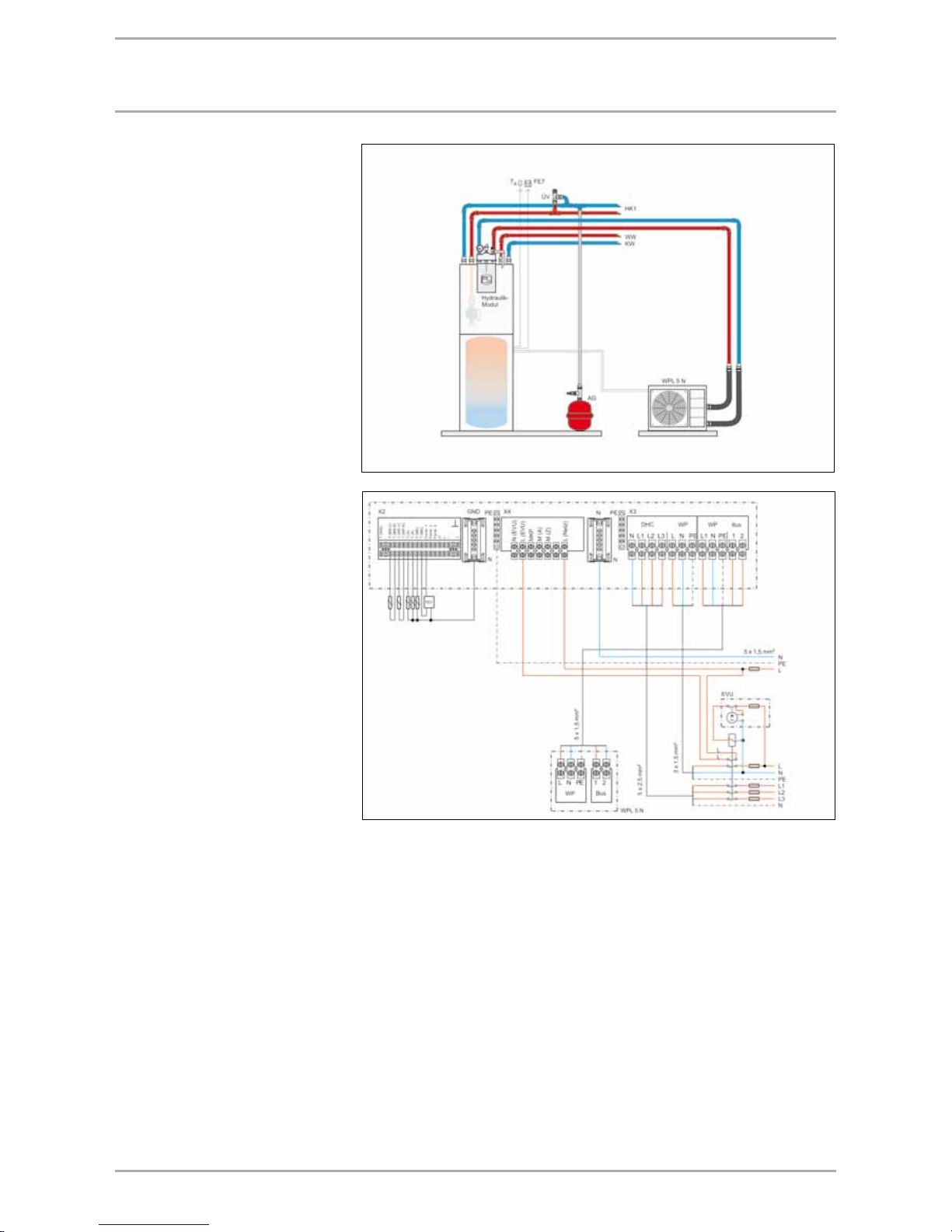
67WWW.STIEBEL-ELTRON.COM
connEctIon wpl 5 n
Heating system connection
For standard heating systems
integrate the heat pump into the
water side according to the standard
circuit. Prior to connecting the heat
pump, check the heating system for
leaks, flush it thoroughly, then fill and
vent it thoroughly. Check the correct
connection of the heating flow and
return. Use the flexible pressure hoses
supplied to reduce structure-borne
noise transmission on the water side.
Implement thermal insulation in
accordance with local regulations.
Power connection
You may need to notify your local
power supply company of the heat
pump connection. All electrical
installation work, particularly earthing
measures, must be carried out in
accordance with local and national
regulations and the requirements of
your local power supply company.
The connection must comply with
the power connection diagram. For
this, also observe the installation
instructions for the heat pump
manager WPMx.
WPL 5N with hydraulic module
WPL 5 N
1/N/PE
230V ~ 50Hz
Domestic
electricity meter
Control phase L
w/o power-OFF
period
Control phase L´
with power-OFF
period
3/N/PE
400V ~ 50Hz
230V ~ 50Hz
Heat pump
electricity meter
T (WW) DHW sensor N EVU Enable signal
T(BW-V) DHW flow L EVU Enable signal
T(BW-R) DHW return MKP Mixer circuit pump
T(WP-V) Heat pump flow M(A) Mixer open
T(WP-R) Heat pump return L Power supply
T(A)
Outside temperature sensor
T(MK) Mixer circuit sensor
Fern1 Remote control
Fern2 Remote control
Fern3 Remote control
Pipeline
Copper 22 x 1.0
single length
max. 10 metres
Page 68

68 WWW.STIEBEL-ELTRON.COM
aIr | watEr HEat pUmp wpl 10
At a glance
For fully automatic heating
water heating up to +60 °C flow
temperature
Suitable for underfloor heating
systems and systems with
radiators; low temperature
heating systems are preferred, as
these achieve a higher coefficient
of performance
Extracts energy from the outside
air, right down to -20 °C outside
temperature
Comprises all components
required for its function and
safety
Central control of the heating
system and safety functions
through the heat pump manager
(essential accessory)
Corrosion-protected, external
casing panels made from zincplated sheet steel with a stove
enamelled finish; internal airways
made from corrosion-resistant
aluminium sheet
Compact design, therefore modest
space requirements for internal or
external installations
Test symbol of independent test
bodies (see type plate)
Contains non-combustible R407C
safety refrigerant
Function
Heat is extracted from the outside air
at temperatures ranging from +30°C
to –20°C by the heat exchanger
on the air side (evaporator).
Heating water is heated in the
heat exchanger on the water side
(condenser) to levels set at the
control unit (from +15 °C to +60 °C)
by heat from the electrical power
used by the compressor. At air
temperatures below approx. +7 °C,
the humidity in the air precipitates as
hoarfrost on the evaporator fins. Any
hoarfrost is automatically defrosted.
Water created from this defrosting
collects in the defrost pan and is
drained off via a hose. The fan is
switched OFF and the heat pump
circuit is reversed to activate the
defrost cycle. The energy required for
defrosting is drawn from the heating
system. The heat pump automatically
reverts to heating mode at the end of
the defrost cycle.
Appliance description WPL 10 A
Compact version for external
installation. The metal enclosure is
zinc-plated and finished in pearlwhite stove enamel. The heat
pump drive unit is equipped with
a hermetically sealed compressor
with crankcase heater, condenser,
evaporator, safety equipment such
as a high/low pressure limiter, and
a frost protection facility. Heating
water up to 75 °C can flow through
the heat pump in idle mode. The
refrigerant used is R407C. The heat
pump is controlled via a BUS cable.
Safety and quality
Appliance description WPL 10 IA
Compact version for internal
installation. The metal enclosure is
zinc-plated and finished in pearlwhite stove enamel. The heat
pump drive unit is equipped with
a hermetically sealed compressor,
condenser, evaporator, safety
equipment such as a high/low
pressure limiter, expansion vessel,
integral control unit, integral diverter
valve for DHW heating and a frost
protection facility. Heating water up
to 75 °C can flow through the heat
pump in idle mode. The refrigerant
used is R407C.
Appliance description WPL 10 I
Compact version for internal
installation. The metal enclosure
is zinc-plated and finished in
pearl-white stove enamel. The
heat pump drive unit is equipped
with a hermetically sealed
compressor, condenser, evaporator,
safety equipment such as a high/
low pressure limiter, and a frost
protection facility. Heating water up
to 75 °C can flow through the heat
pump in idle mode. The refrigerant
used is R407C. The heat pump is
controlled via a BUS cable.
Page 69

69WWW.STIEBEL-ELTRON.COM
Type WPL 10
Part no. external installation 22 08 12
Part no. internal installation 22 08 11
Part no. compact internal installation 22 08 26
Specification
Application limits WQA °C -20 to +30
Flow temperature WNA °C +15 to +60 (below -10 °C outside temperature to +50 °C)
Air flow rate WQA m³/h 1200
External static pressure differential Pa 100
Flow rate, heating side m³/h 1.40
Pressure diff., heating side hPa 195
Heating flow/return connection Inches G 1¼" (male)
Air hose connection mm 407 x 152 oval
Refrigerant R407C
Fill weight kg 2.7
Electrical details
Compressor power supply connection n x mm² 5 x 2.5 cable cross-section acc. to type of routing (observe VDE 0298-4)
Booster heater power supply connection
n x mm² 5 x 2.5 cable cross-section acc. to type of routing (observe VDE 0298-4)
Control cable n x mm² 5 x 1.5
Flow sensor lead n x mm² 3 x 1.5
BUS cable n x mm² J-Y (St) 2 x 2 x 0.8
Fuse - compressor A C 16A all poles
Electrical booster heater fuse A C 16A
Control circuit fuse A C 16A
Protection EN 60529 IP 14 B
Voltage/frequency load V/Hz 3/PE ~ 400 V 50 Hz
Booster heater connection V/Hz 3/N/PE ~ 400 V 50 Hz, 8.8 kW
Voltage/frequency control V/Hz 1/N/PE ~ 230 V / 50 Hz
Starting current A < 25
Weight and dimensions
H x W x D (external installation) mm 1245 x 967 x 1122
H x W x D (internal installation) mm 1010 x 758 x 856
H x W x D (internal installation compact)
mm 1668 x 778 x 925
Weight (external/internal) kg 140
Weight (compact) kg 185
Other model characteristics
Corrosion protection zinc-plated
Compliant with safety regulations UVV/VDE/GS
External sound power level dB(A) 65
Internal sound power level dB(A) 57/62
Sound pressure level at a distance of 5 m
dB(A) 43
Output details
Air temperature °C –7 +2 +10
Flow temperature °C +35 +35 +35
Heating output kW 5.4 6.7 8.7
Power consumption kW 1.8 2.1 2.2
COP ε 2.7 3.3 4.0
Temperature differential at A2/W35 K 6.7
aIr | watEr HEat pUmp wpl 10
Page 70

70 WWW.STIEBEL-ELTRON.COM
oUtpUt dEtaIlS wpl 10
Air|water heat pump WPL 10
Heating output (kW), power consumption (kW) and coefficient of performance ε
Heat
source
temp. °C
Heating output Power consumption COP
35 °C 50 °C 60 °C 35 °C 50 °C 60 °C 35 °C 50 °C 60 °C
kW kW kW kW kW kW ε ε ε
–15 3.5 2.8 – 1.5 1.6 – 2.3 1.8 –
–10 4.4 3.7 2.8 1.7 1.9 1.7 2.6 2.0 1.7
–5 5.3 4.6 3.7 1.9 2.1 1.9 2.8 2.2 2.0
0 6.0 5.4 4.6 2.0 2.2 2.2 3.0 2.4 2.1
+5 7.2 6.6 6.0 2.2 2.4 2.4 3.3 2.7 2.5
+10 8.7 8.0 7.4 2.2 2.6 2.8 4.0 3.1 2.6
+15 9.8 8.9 8.2 2.3 2.7 3.0 4.3 3.3 2.7
+20 10.9 9.7 9.0 2.3 2.8 3.1 4.7 3.5 2.9
Flow temperature 35 °C
Flow temperature 50 °C
Air inlet temperature °C
Heating output (kW)
Page 71
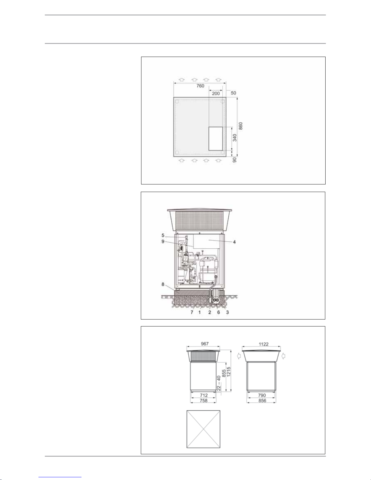
71WWW.STIEBEL-ELTRON.COM
General information
Ensure that the surface on which
the heat pump is to be installed,
is horizontal, level, solid and
permanent. The entire heat pump
frame should be in contact with the
substrate. Uneven substrates can
increase the acoustic emissions of the
heat pump. The heat pump must be
accessible from all sides.
Special features
Recommended substrate:
Cast concrete foundation
Kerb stones
Stone slabs
Provide a recess (space) underneath
the heat pump to enable water and
electrical pipes/cables to be connected
from below.
Protection of heating water lines
against frost and moisture
Protect the flow and return lines in
external installations against frost by
means of adequate thermal insulation
and by routing them inside conduit
to protect them against moisture.
Insulation thickness in accordance
with current regulations. The integral
frost stat (inside the heat pump) that
automatically starts the circulation
pump in the heat pump circuit at <+10
°C and thereby safeguards circulation
in all water-bearing components,
offers additional frost protection. Fill
the heating system with an antifreeze
mixture if the power supply cannot
be guaranteed for a longer period of
time.
Condensate drain
Route the condensate drain hose with
a downward slope or to the side out
of the heat pump. When installing
the heat pump outside, route the
condensate to an existing drain or into
a coarse gravel soakaway. For this,
ensure an installation that is free from
the risk of frost.
Foundation for external installation of the WPL 10
Water and power connections WPL 10 external installation
1 Condensate drain
2 Heating flow
3 Heating return
4 Control panel
5 Air vent valve
6 Installation pipe
7 Coarse gravel
8 Concrete foundations
9
High limit safety cut-out
DHC cartridge 3D-C
Air discharge
Air inlet
Dimensions in
mm
External installation of the WPL 10
Dimensions in mm
exteRnal installation Wpl 10
Page 72

72 WWW.STIEBEL-ELTRON.COM
inteRnal installation Wpl 10
Internal installation WPL 10
1 Heat pump
2 Impact sound insulation
3 Floating screed
Screed and impact sound
insulation. Recess
if provided.
Water and power connections WPL 10 internal installation
1 Condensate drain
2 Heating flow
3 Heating return
4 Control panel
5 Air vent valve
6
High limit safety cut-out
DHC cartridge 3D-C
Internal installation WPL 10
Dimensions in mm
Air routing with hoses
The total length of hoses on the air
inlet and discharge side must not
exceed 8 m. Never incorporate more
than four 90° bends.
The hose will tend to sag because
of its flexibility; therefore secure
it in approx. 1 m intervals. Special
hoses are used to route the inlet
air from the outside to the heat
pump and discharge air from the
heat pump to the outdoors. These
hoses are highly flexible, thermally
insulated and are self-extinguishing
in case of fire. Thermally insulated
hoses are available in 3 m lengths
(li Ø 400 mm).
Air routing with air ducts
With air routes longer than 8 m,
air ducts can also be connected to
the heat pump. The cross-section of
the air duct varies according to the
air flow rate and according to the
externally prevailing, static pressure
differential of the heat pump. To
reduce the transfer of structure-borne
noise in the building, install an air
hose or canvas flange between the
heat pump and the air ducts. When
sizing air ducts and grilles, observe
the external pressure of the fan.
Special features
If the heat pump is installed in an
enclosed room containing combustion
appliance that takes its a combustion
air directly from the room (open flue
operation), then a ventilation aperture
to the installation location with 250
cm² diameter is required, to prevent
the heat pump from influencing the
operation of the gas or oil burner.
Without this additional ventilation,
small, unavoidable leakages on the
air inlet side, e.g. at hose connectors
or at the heat pump, will reduce the
air pressure in the enclosed room to
unacceptable levels.
Page 73

73WWW.STIEBEL-ELTRON.COM
Internal installation WPL 10
Internal installation WPL 10
aIr roUtIng - IntErnal InStallatIon
Air hose
Wall outlet
Part no. 22 22 30
Dimensions in mm
(minimum clearances)
Wall outlet
Wall
outlet
Air hose
Wall outlet
Part no. 22 22 30
Dimensions in mm
(minimum clearances)
Wall outlet
Wall outlet
Page 74

74 WWW.STIEBEL-ELTRON.COM
aIr roUtIng - IntErnal InStallatIon
Internal installation WPL 10
Internal installation WPL 10
Air hose
Wall outlet
Part no. 22 22 30
Dimensions in mm
(minimum clearances)
Air hose
Wall outlet
Part no. 22 22 30
Dimensions in mm
(minimum clearances)
Wall outlet
Wall outlet
Wall outlet
Wall outlet
Page 75

75WWW.STIEBEL-ELTRON.COM
aIr roUtIng - IntErnal InStallatIon
Internal installation WPL 10 compact
Internal installation WPL 10 compact
Wall outlet
Part no. 22 22 30
Dimensions in mm
(minimum clearances)
Wall outlet
Part no. 22 22 30
Dimensions in mm
(minimum clearances)
Wall outlet Wall outlet
Wall outlet
Page 76
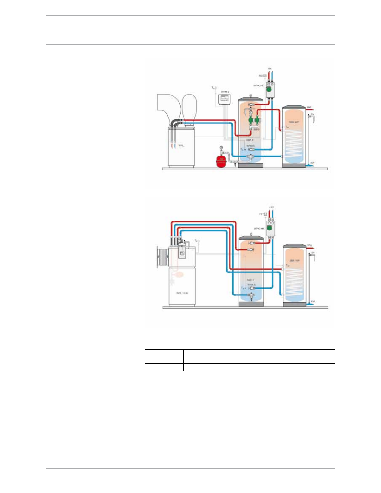
76 WWW.STIEBEL-ELTRON.COM
HEatIng SyStEm connEctIon wpl 10
Heating system connection
Install the heat utilisation system
(WNA) in accordance with the design
documentation. For standard heating
systems integrate the heat pump into
the water side according to standard
circuits (see appendix). Prior to
connecting the heat pump, check
the heating system for leaks, flush it
thoroughly, fill and vent it thoroughly.
Check the correct connection of the
heating flow and return. Flexible
pressure hoses are recommended to
reduce structure-borne noise on the
water side. The required circulation
pump and the pipe cross-section can
be determined from the table below.
Fit thermal insulation in accordance
with local regulations. When using
the compact installation WPKI 5, use
the following circulation pumps: see
table.
Circulation pump for the heat pump with WPKI 5
(between the heat pump and the buffer cylinder; max. pipe length 10 m)
Heat pump Flow rate
m³/h
Pressure differential
hPa
Circulation pump
Type
Copper pipe
DN
WPL 10 1.0 200 UP 25 - 60 22 x 1.0
WPL with buffer cylinder SBP 700 and DHW heating
Page 77

77WWW.STIEBEL-ELTRON.COM
powEr SUpply wpl 10
Power supply
You may need to notify your local
power supply company of the heat
pump connection.
All electrical installation work,
particularly earthing measures, must
be carried out in accordance with
local and national regulations and
the requirements of your local power
supply company. The connection must
comply with the power connection
diagram. For this, also observe the
installation instructions for the heat
pump manager WPM II.
For external installation
Use only cables suitable for external
use to VDE 0100 [or local regulations].
Route such cables through a conduit
(protective pipe); entry into the heat
pump only from below.
For internal installation
Route the cables through the
installation aperture in the side of the
heat pump.
Electrical specification of the heat pump
Heat pump
Power
consumption
kW
Max. operating
current
A
Starting
current R start
A
Power cable
mm²
Fuse
protection
A
WPL 10 2.2 6.0 <25 5 x 2.5 *
C 16A all poles
* Cable cross-section acc. to type of routing (observe VDE 0298-4 [or local regulations])
WPL
3/N/PE
230V ~ 50Hz
Domestic
electricity meter
Control phase L
w/o power-OFF
period
Control phase L´
with power-OFF
period
3/N/PE
400V ~ 50Hz
Heat pump
electricity meter
M1 = Circulation pump (max. 2A gl)
WPL IK
3/N/PE
230V ~ 50Hz
Domestic
electricity meter
Control phase L
w/o power-OFF
period
Control phase L´
with power-OFF
period
3/N/PE
400V ~ 50Hz
Heat pump
electricity meter
Impuls Pulse input WP L Power supply
B2
Temperature sensor heat pump return
KOKP Collector circuit pump
Fühler 1 Temp. sensor, heat meter/solar MKP Mixer circuit pump
Fühler 2 Temp. sensor, heat meter/solar EVU Enable signal
T (WW) Temperature sensor, DHW Pumpe Power supply
T(2.WE) Temperature sensor heat source 2 M(A) Mixer open
T(A) Outside temperature sensor M(Z) Mixer closed
T(MK) Temperature sensor, mixer circuit HKP Heating circuit pump
Fern1 Remote control 2.WE Heat source 2
Fern3 Remote control ZKP DHW circulation pump
Page 78

78 WWW.STIEBEL-ELTRON.COM
aIr | watEr HEat pUmpS wpl 13/18/23 E/cool
Appliance description WPL..E
Air | water heat pump with low
space requirement through compact
design for optional internal or
external installation. The metal
enclosure is zinc-plated and finished
in a white stove enamel. The booster
heater is fitted as standard to enable
mono-energetic operation and high
DHW temperatures. The evaporator is
defrosted by reversing the cycle. The
electronic expansion valve optimises
the coefficient of performance over
the entire application range. The
heat pump is filled with CFC-free
R407 C refrigerant. The heat pump is
controlled via a BUS cable.
At a glance
For fully automatic heating
water heating up to +60 °C flow
temperature
Suitable for underfloor heating
systems and systems with
radiators; low temperature
heating systems are preferred, as
these achieve a higher coefficient
of performance
Extracts energy from the outside
air, right down to -20 °C outside
temperature
Comprises all components
required for its function and
safety
Central control of the heating
system and safety functions
through the heat pump manager
(essential accessory)
Corrosion-protected, external casing
panels made from zinc-plated
sheet steel with a stove enamelled
finish; internal airways made from
corrosion-resistant aluminium sheet
Compact design, therefore modest
space requirements for internal or
external installations
Test symbol of independent test
bodies (see type plate)
Contains non-combustible R407C
safety refrigerant
Function
Heat is extracted from the outside air
at temperatures ranging from +40°C
to –20°C by the heat exchanger on
the air side (evaporator). Heating
water is heated in the heat exchanger
on the water side (condenser) to
levels set at the control unit (from
+15 °C to +60 °C) by heat from
the electrical power used by the
compressor. At air temperatures
below approx. +7 °C, the humidity
in the air precipitates as hoarfrost
on the evaporator fins. Any hoarfrost
is automatically defrosted. Water
created from this defrosting collects
in the defrost pan and is drained
off via a hose. The fan is switched
OFF and the heat pump circuit is
reversed to activate the defrost cycle.
The energy required for defrosting
is drawn from the heating system.
The heat pump automatically reverts
to heating mode at the end of the
defrost cycle.
Safety and quality
Appliance description WPL..cool
Air | water heat pump with low
space requirement through compact
design for optional internal or
external installation with cooling
function. The metal enclosure is
zinc-plated and finished in a white
stove enamel. The booster heater is
fitted as standard to enable monoenergetic operation and high DHW
temperatures. The evaporator is
defrosted by reversing the cycle. The
electronic expansion valve optimises
the coefficient of performance over
the entire application range. The
heat pump is filled with CFC-free
R407 C refrigerant. The heat pump is
controlled via a BUS cable.
Page 79

79WWW.STIEBEL-ELTRON.COM
aIr | watEr HEat pUmpS wpl 13/18/23 E/cool
Type WPL 13 E/cool WPL 18 E/cool WPL 23 E/cool
Part no. standard appliance E 22 77 56 22 77 57 22 77 58
Part no. standard appliance cool 22 34 00 22 34 01 22 34 02
Part no. casing (external installation) 07 44 13 07 44 13 07 44 13
Part no. casing (internal installation) 07 44 12 07 44 12 07 44 12
Specification
Application limits WQA °C -20 to +40
Flow temperature WNA °C +15 to +60
Air flow rate WQA m³/h 3200 3500 3500
External static pressure differential Pa 100 100 100
Flow rate, heating side m³/h 1.50 2.00 2.80
Pressure diff., heating side hPa 105 145 190
Heating flow/return connection Inches G 1¼" (male)
Air hose connection mm 721 x 248 oval 721 x 248 oval 721 x 248 oval
Refrigerant R407C
Fill weight kg 5.9 5.9 5.9
Electrical details
Compressor power supply connection n x mm² 5 x 2.5 cable cross-section acc. to type of routing (observe VDE 0298-4)
Booster heater power supply connection
n x mm² 5 x 2.5 cable cross-section acc. to type of routing (observe VDE 0298-4)
Control cable n x mm² 5 x 1.5
BUS cable n x mm² J-Y (St) 2 x 2 x 0.8
Fuse - compressor A C 16A all poles
Electrical booster heater fuse A C 16A
Control circuit fuse A C 16A
Protection EN 60529 IP 14?B
Voltage/frequency load V/Hz 3/PE ~ 400 V 50 Hz
Booster heater connection V/Hz 3/N/PE ~ 400 V 50 Hz, 8.8 kW
Voltage/frequency control V/Hz 1/N/PE ~ 230 V / 50 Hz
Starting current A <30 <30 <30
Weight and dimensions
H x W x D (standard appliance) mm 1116 x 1182 x 784
H x W x D (external installation) mm 1434 x 1240 x 1280
H x W x D (internal installation) mm 1182 x 1240 x 800
Weight (standard appliance) kg 210 220 225
Total weight (external/internal) kg 240/220 250/230 255/235
Other model characteristics
Corrosion protection zinc-plated
Compliant with safety regulations UVV/VDE/GS
External sound power level dB(A) 65
External installation with sound insulation (accessory)
dB(A) 63
Internal sound power level dB(A) 56/62 57/62 58/62
Sound pressure level at a distance of 5 m
dB(A) 43
Output details, heating
Air temperature °C –7 +2 +10 –7 +2 +10 –7 +2 +10
Flow temperature °C +35 +35 +35 +35 +35 +35 +35 +35 +35
Heating output kW 6.6 8.1 9.5 9.6 11.3 13.3 13.0 14.8 17.8
Power consumption kW 2.2 2.4 2.3 3.0 3.0 2.9 4.2 4.2 4.2
COP ε 3.0 3.4 4.1 3.2 3.7 4.6 3.1 3.5 4.2
Temperature differential at A2/W35 K 4.5 4.5 4.5
Output details cooling capacity
Air temperature °C +30 +30 +30 +30 +30 +30 +30 +30 +30
Flow temperature °C +7 +15 +20 +7 +15 +20 +7 +15 +20
Cooling capacity kW 7.0 8.6 10.1 9.7 12.1 13.9 12.7 16.0 17.6
Power consumption kW 2.5 2.8 3.0 3.5 3.9 4.2 5.5 6.1 6.4
COP ε 2.8 3.1 3.4 2.8 3.1 3.3 2.3 2.6 2.8
Page 80
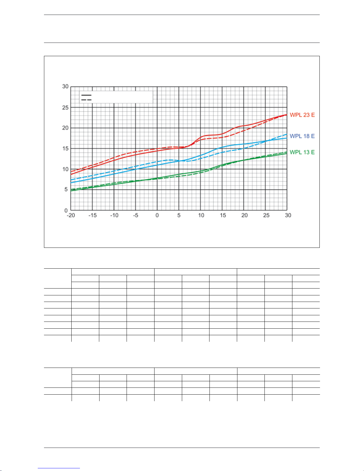
80 WWW.STIEBEL-ELTRON.COM
oUtpUt dEtaIlS wpl 13/18/23 E/cool
Flow temperature 35 °C
Flow temperature 50 °C
Air inlet temperature °C
Heating output (kW)
Air | water heat pump WPL 13 E/cool (heating mode)
Heating output (kW), power consumption (kW) and coefficient of performance ε
Heat source
temp. °C
Heating output Power consumption COP
35 °C 50 °C 60 °C 35 °C 50 °C 60 °C 35 °C 50 °C 60 °C
kW kW kW kW kW kW ε ε ε
–15 5.4 5.6 5.8 2.1 2.8 3.3 2.6 2.0 1.8
–10 6.1 6.4 6.6 2.2 2.9 3.4 2.8 2.2 1.9
–5 6.9 7.0 7.3 2.2 2.9 3.5 3.1 2.4 2.1
0 7.8 7.7 7.8 2.4 2.9 3.7 3.3 2.6 2.1
+5 8.6 8.3 8.4 2.3 3.0 3.6 3.7 2.8 2.3
+10 9.5 8.8 8.9 2.3 2.8 3.4 4.1 3.1 2.6
+15 11.0 10.7 10.1 2.5 3.0 3.5 4.4 3.6 2.9
+20 12.1 12.0 11.3 2.5 3.1 3.6 4.8 3.9 3.1
Air|water heat pump WPL 13 cool (cooling mode)
Cooling capacity (kW), power consumption (kW) and coefficient of performance ε
Heat source
temp. °C
Cooling capacity Power consumption COP
7 °C 15 °C 20 °C 7 °C 15 °C 20 °C 7 °C 15 °C 20 °C
kW kW kW kW kW kW ε ε ε
+30 7.0 8.6 10.1 2.5 2.8 3.0 2.8 3.1 3.4
+35 6.6 8.3 9.7 2.8 3.0 3.2 2.4 2.8 3.0
Page 81

81WWW.STIEBEL-ELTRON.COM
oUtpUt dEtaIlS wpl 13/18/23 E/cool
Air | water heat pump WPL 18 E/cool (heating mode)
Heating output (kW), power consumption (kW) and coefficient of performance ε
Heat source
temp. °C
Heating output Power consumption COP
35 °C 50 °C 60 °C 35 °C 50 °C 60 °C 35 °C 50 °C 60 °C
kW kW kW kW kW kW ε ε ε
–15 7.7 8.2 8.7 2.9 3.9 4.9 2.7 2.1 1.8
–10 8.9 9.4 9.8 3.0 4.0 5.0 3.0 2.3 2.0
–5 10.0 10.5 10.7 3.0 4.1 5.0 3.3 2.6 2.1
0 10.9 11.5 11.4 3.0 4.1 5.0 3.6 2.8 2.3
+5 11.9 11.7 11.4 2.9 3.9 4.7 4.0 3.0 2.4
+10 13.3 12.6 12.0 2.9 3.8 4.6 4.6 3.3 2.6
+15 15.2 14.2 13.6 3.0 3.9 4.7 5.1 3.6 2.9
+20 16.1 15.2 14.6 3.0 3.9 4.7 5.3 3.8 3.1
Air | water heat pump WPL 23 E/cool (heating mode)
Heating output (kW), power consumption (kW) and coefficient of performance ε
Heat source
temp. °C
Heating output Power consumption COP
35 °C 50 °C 60 °C 35 °C 50 °C 60 °C 35 °C 50 °C 60 °C
kW kW kW kW kW kW ε ε ε
–15 10.4 11.1 11.7 3.9 5.2 6.7 2.7 2.1 1.7
–10 12.0 12.7 13.2 4.1 5.5 6.8 2.9 2.3 2.0
–5 13.4 14.0 14.4 4.2 5.6 6.8 3.2 2.5 2.1
0 14.4 14.9 15.2 4.2 5.7 6.9 3.4 2.6 2.2
+5 15.1 15.4 15.6 4.1 5.5 6.5 3.6 2.8 2.4
+10 17.8 17.2 16.7 4.2 5.3 6.3 4.2 3.2 2.6
+15 18.4 17.7 17.4 4.3 5.5 6.7 4.3 3.2 2.6
+20 20.4 19.3 18.9 4.3 5.6 6.9 4.7 3.4 2.7
Air|water heat pump WPL 18 cool (cooling mode)
Cooling capacity (kW), power consumption (kW) and coefficient of performance ε
Heat source
temp. °C
Cooling capacity Power consumption COP
7 °C 15 °C 20 °C 7 °C 15 °C 20 °C 7 °C 15 °C 20 °C
kW kW kW kW kW kW ε ε ε
+30 9.7 12.1 13.9 3.5 3.9 4.2 2.8 3.1 3.3
+35 9.2 11.8 13.5 3.9 4.1 4.5 2.4 2.8 3.0
Air|water heat pump WPL 23 cool (cooling mode)
Cooling capacity (kW), power consumption (kW) and coefficient of performance ε
Heat source
temp. °C
Cooling capacity Power consumption COP
7 °C 15 °C 20 °C 7 °C 15 °C 20 °C 7 °C 15 °C 20 °C
kW kW kW kW kW kW ε ε ε
+30 12.7 16.0 17.6 5.5 6.1 6.4 2.3 2.6 2.8
+35 11.4 14.9 16.6 5.8 6.5 7.0 2.0 2.3 2.4
Page 82

82 WWW.STIEBEL-ELTRON.COM
Foundation for external installation of the WPL 13/18/23 E/cool
1 Condensate drain
2 Heating return
3 Heating flow
4 Control panel
5 Air vent valve
6 Installation pipe
7 Coarse gravel
8 Concrete foundations
9
High limit safety cut-out
DHC cartridge 3D-C
Air discharge
Air inlet
Dimensions in mm
Internal installation WPL 13/18/23 E/cool
Dimensions in mm
ExtErnal InStallatIon wpl 13/18/23 E/cool
General information
Ensure that the surface on which
the heat pump is to be installed,
is horizontal, level, solid and
permanent. The entire heat pump
frame should be in contact with the
substrate. Uneven substrates can
increase the acoustic emissions of the
heat pump. The heat pump must be
accessible from all sides.
Special features
Recommended substrate:
Cast concrete foundation
Kerb stones
Stone slabs
Provide a recess (space) underneath
the heat pump to enable water and
electrical pipes/cables to be connected
from below.
Protection of heating water lines
against frost and moisture
Protect the flow and return lines in
external installations against frost by
means of adequate thermal insulation
and by routing them inside conduit
to protect them against moisture.
Insulation thickness in accordance
with current regulations. The integral
frost stat (inside the heat pump) that
automatically starts the circulation
pump in the heat pump circuit at
<+10°C and thereby safeguards
circulation in all water-bearing
components, offers additional frost
protection. Fill the heating system
with an antifreeze mixture if the
power supply cannot be guaranteed
for a longer period of time.
Condensate drain
The condensate drain hose must be
routed with a slope downwards or
to the side out of the heat pump.
When installing the heat pump
outside, route the condensate to
an existing drain or into a coarse
gravel soakaway. For this, ensure an
installation that is free from the risk
of frost.
Internal installation WPL 13/18/23 E/cool
Page 83
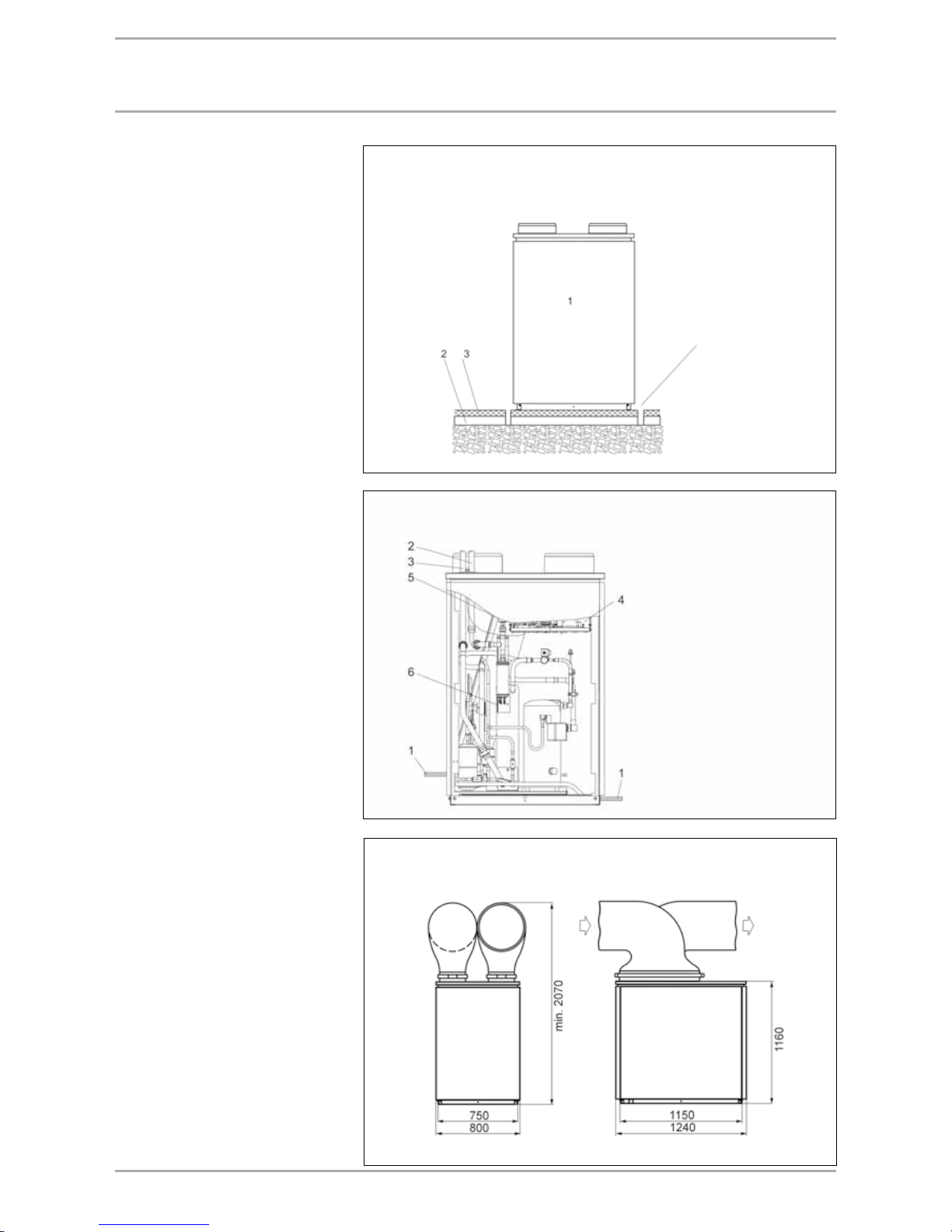
83WWW.STIEBEL-ELTRON.COM
Internal installation WPL 13/18/23 E/cool
1 Condensate drain
2 Heating flow
3 Heating return
4 Control panel
5 Air vent valve
6
High limit safety cut-out
DHC cartridge 3D-C
Internal installation WPL 13/18/23 E/cool
1 Heat pump
2 Impact sound insulation
3 Floating screed
Screed and impact sound
insulation. Recess
if provided.
Internal installation WPL 13/18/23 E/cool
Dimensions in mm
Air routing with hoses
The total length of hoses on the air
inlet and discharge side must not
exceed 8 m. Never incorporate more
than four 90° bends.
The hose will tend to sag because of
its flexibility; therefore secure it in
approx. 1 m intervals. Special hoses
are used to route the inlet air from
the outside to the heat pump and
expelled air from the heat pump
to the outdoors. These hoses are
highly flexible, thermally insulated
and are self-extinguishing in case of
fire. Thermally insulated hoses are
available in 3 m and 4 m lengths
(li Ø 560 mm).
Air routing with air ducts
With air routes longer than 8 m,
air ducts can also be connected to
the heat pump. The cross-section of
the air duct varies according to the
air flow rate and according to the
externally prevailing, static pressure
differential of the heat pump. To
reduce the transfer of structure-borne
noise in the building, install an air
hose or canvas flange between the
heat pump and air ducts. When sizing
air ducts and grilles, observe the
external pressure of the fan.
Special features
If the heat pump is installed in
an enclosed room, containing a
combustion appliance that takes
its combustion air directly from
the room (open flue operation),
then a ventilation aperture to the
installation location with 250 cm²
diameter is required, to prevent the
heat pump from influencing the
operation of the gas or oil burner.
Without this additional ventilation,
small, unavoidable leakages on the
air inlet side, e.g. at hose connectors
or at the heat pump, will reduce the
air pressure in the enclosed room to
unacceptable levels.
IntErnal InStallatIon wpl 13/18/23 E/cool
Page 84

84 WWW.STIEBEL-ELTRON.COM
Internal installation WPL 13/18/23 E/cool, WPL 33 - incl. accessories: Insulated wall outlet
Internal installation WPL 13/18/23 E/cool, WPL 33 - incl. accessories: Hose connection plate
aIr roUtIng - IntErnal InStallatIon
Dimensions in mm
(minimum clearances)
Wall outlet
Hose
Hose
connection
plate
118 x 78
Dimensions in mm
(minimum clearances)
Cellar
window
Hose
Cellar
window
Wall outlet
Page 85

85WWW.STIEBEL-ELTRON.COM
Internal installation WPL 13/18/23 E/cool, WPL 33 - incl. accessories: Insulated wall outlet
Internal installation WPL 13/18/23 E/cool, WPL 33 - incl. accessories: Hose connection plate
aIr roUtIng - IntErnal InStallatIon
Dimensions in mm
(minimum clearances)
Air hose
Cellar
window
Hose
connection
plate
118 x 78
Dimensions in mm
(minimum clearances)
Air hose
Wall outlet
Page 86

86 WWW.STIEBEL-ELTRON.COM
Internal installation WPL 13/18/23 E/cool, WPL 33 - incl. accessories: Insulated wall outlet
Internal installation WPL 13/18/23 E/cool, WPL 33 - incl. accessories: Hose connection plate
aIr roUtIng - IntErnal InStallatIon
Dimensions in mm
(minimum clearances)
Cellar
window
Cellar
window
Wall outlet
Wall outlet
Page 87

87WWW.STIEBEL-ELTRON.COM
aIr roUtIng of wpl 13/18/23 E for IntErnal InStallatIonS
WPIC
for heat pumps WPL 13/18/23 E
Type WPIC
Part no. 18 79 09
Specification
Voltage / frequency V 1/N/PE ~ 230 V / 50 Hz
Pipe connections
Inches
G 1¼" (male)
Breaking capacity of the relay A 2
Nominal flow rate WPL 13/18/23 m³/h 1.0/1.2/1.4
Available pressure differential WPL 13/18/23
hPa 420/345/265
Weight and dimensions
Height mm 637
Width mm 1240
Depth mm 800
Weight kg 80
Function
Air ducts for the inlet and discharge
apertures of the WPL 13/18/23 for
internal installation are integrated
into the WPL function module in
a single enclosure. Part of the
accessories are the side casing
panels of the heat pump and the
ready-made air hoses. The heat
pump manager WPM II, circulation
pumps for heating the buffer and
DHW cylinders, the flow and return
temperature sensor as well as the
safety equipment are also fitted at the
factory. The installation on the heat
pump is facilitated through two antivibration dampers (pack supplied).
WPL 13/18/23 E with WPIC
10
Circulation pump, heating circuit
11 DHW circulation pump
12 Flow pressure hose
13 Return pressure hose
14 Lid connection bracket
15 WPL control panel
16 Dirt trap
17 Check valve
18 High limit safety cut-out
DHC cartridge 3D-C
Air routing
Secure the ready-made air hoses on
the cover with the supplied wing nuts.
A drilling template is provided inside
the cover for marking the fixing holes
on the wall. Subject to wall structure,
use suitable rawl plugs and screws to
fix the mounting plate to the wall.
Installation mass WPL with WPIC
1 Heat pump manager
2 Air hose with
wall connection plate
3 Safety equipment
4 DHW flow
5 DHW return
6 Buffer cylinder flow
7 Buffer cylinder flow
8 Cable entry, power cables
9
Wall connection plate dimensions
Dimensions in mm
Page 88

88 WWW.STIEBEL-ELTRON.COM
HEatIng SyStEm connEctIon wpl 13/18/23 E/cool
Heating system connection
Install the heat utilisation system
(WNA) in accordance with the
design documentation. For standard
heating systems integrate the heat
pump into the water side according
to standard circuits (see appendix).
Prior to connecting the heat pump,
check the heating system for leaks,
flush it thoroughly, then fill and
vent it thoroughly. Check the correct
connection of the heating flow and
return. Flexible pressure hoses are
recommended to reduce structureborne noise on the water side. The
required circulation pump and the
pipe cross-section can be determined
from the table below. Fit thermal
insulation in accordance with local
regulations. When using the compact
installation WPKI 5, use the following
circulation pumps: see table.
Circulation pump for the heat pump with WPKI 5
(between the heat pump and the buffer cylinder; max. pipe length 10 m)
Heat pump Flow rate
m³/h
Pressure differential
hPa
Circulation pump
Type
Copper pipe
DN
WPL 13 E 1.5 105 UP 25 - 60 28 x 1.5
WPL 18 E 2.0 145 UP 25-80 35 x 1.5
WPL 23 E 2.8 190 UP 25-80 35 x 1.5
WPL 13 cool 1.5 105 UP 25 - 60 28 x 1.5
WPL 18 cool 2.0 145 UP 25-80 35 x 1.5
WPL 23 cool 2.8 190 UP 25-80 35 x 1.5
WPL with buffer cylinder SBP 700 and DHW heating
WPL/WPIC with SBP 700 buffer cylinder and DHW heating
Page 89

89WWW.STIEBEL-ELTRON.COM
powEr SUpply wpl 13/18/23 E/cool
Power supply
You may need to notify your local
power supply company of the heat
pump connection.
All electrical installation work,
particularly earthing measures, must
be carried out in accordance with
local and national regulations and
the requirements of your local power
supply company. The connection must
comply with the power connection
diagram. For this, also observe the
installation instructions for the heat
pump manager WPM II.
For external installation
Use only cables suitable for external
use to VDE 0100 [or local regulations].
Route such cables through a conduit
(protective pipe); entry into the heat
pump only from below.
For internal installation
Route the cables through the
installation aperture in the side of the
heat pump.
Electrical specification of the heat pump
Heat pump
Power
consumption
kW
Max. operating
current
A
Starting
current R start
A
Power cable
mm²
Fuse
protection
A
WPL 13 E 2.7 8.0 24 5 x 2.5 *
C 16A all poles
WPL 18 E 3.5 10.6 26 5 x 2.5 *
C 16A all poles
WPL 23 E 3.9 11.4 29 5 x 2.5 *
C 16A all poles
* Cable cross-section acc. to type of routing (observe VDE 0298-4 [or local regulations])
WPL
3/N/PE
230V ~ 50Hz
Domestic
electricity meter
Control phase L
w/o power-OFF
period
Control phase L´
with power-OFF
period
3/N/PE
400V ~ 50Hz
Heat pump
electricity meter
M1 = Circulation pump (max. 2A gl)
WPL + WPIC
3/N/PE
230V ~ 50Hz
Domestic
electricity meter
Control phase L
w/o power-OFF
period
Control phase L´
with power-OFF
period
3/N/PE
400V ~ 50Hz
Heat pump
electricity meter
Impuls Pulse input WP L Power supply
T (HRL)
Temperature sensor heat pump return
ZKP DHW circulation pump
Fühler 1 Temp. sensor, heat meter/solar EVU Enable signal
Fühler 2 Temp. sensor, heat meter/solar HKP Heating circuit pump
T (WW) Temperature sensor, DHW 2.WE Heat source 2
T(2.WE) Temperature sensor heat source 2 M(A) Mixer open
T(A) Outside temperature sensor M(Z) Mixer closed
T(MK) Temperature sensor, mixer circuit MKP Mixer circuit pump
Fern1 Remote control KOKP Collector circuit pump
Fern3 Remote control
Page 90

90 WWW.STIEBEL-ELTRON.COM
aIr | watEr HEat pUmp wpl 33
Function
Heat is extracted from the outside air
at temperatures ranging from +30°C
to –20 °C by the heat exchanger on
the air side (evaporator). Heating
water is heated to flow temperature
levels in the heat exchanger on
the water side (condenser) by this
extracted heat and additional heat
from the electrical power used by
the compressor. The heat pump
manager (WPM) matches the heat
pump heating output in two stages
to the actual heat demand. At air
temperatures below approx. +10 °C,
the humidity in the air precipitates as
hoarfrost on the evaporator fins. Any
hoarfrost is automatically defrosted.
Water created from this defrosting
collects in the defrost pan and is
drained off via a hose. The fan is
switched OFF and the heat pump
circuit is reversed to activate the
defrost cycle. The energy required for
defrosting is drawn from the heating
system. The heat pump automatically
reverts to heating mode at the end of
the defrost cycle.
Appliance description
High flexibility with a low space
requirement through compact design
for optional internal or external
installation. The metal enclosure is
zinc-plated and finished in a white
stove enamel. The booster heater is
fitted as standard to enable monoenergetic operation and high DHW
temperatures. The evaporator is
defrosted by reversing the cycle.
Heating water up to 75 °C can flow
through the heat pump in idle mode.
It is equipped as standard with all
safety equipment, such as a high/low
pressure limiter, frost protection and
the necessary starting current limiter.
The heat pump is filled with
HCFC-free R407 C refrigerant. The
heat pump is controlled via a BUS
cable.
At a glance
For fully automatic heating
water heating up to +60 °C flow
temperature
Suitable for underfloor heating
systems and systems with
radiators; low temperature
heating systems are preferred, as
these achieve a higher coefficient
of performance
Extracts energy from the outside
air, right down to -20 °C outside
temperature
Comprises all components
required for its function and
safety
Central control of the heating
system and safety functions
through the heat pump manager
(essential accessory)
Corrosion-protected, external
casing panels made from zincplated sheet steel plus stove
enamelled finish; internal airways
made from corrosion-resistant
aluminium sheet
Compact design, therefore modest
space requirements for internal or
external installations
Test symbol of independent test
bodies (see type plate)
Contains non-combustible R407C
safety refrigerant
Safety and quality
Page 91

91WWW.STIEBEL-ELTRON.COM
Type WPL 33
Part no. standard unit 18 53 48
Part no. casing (external installation) 18 53 69
Part no. casing (internal installation) 18 53 68
Specification
Application limits WQA °C -20 to +30
Flow temperature WNA °C +15 to +60
Air flow rate WQA m³/h 3500
External static pressure differential Pa 100
Flow rate, heating side m³/h 1.40
Pressure diff., heating side hPa 190
Heating flow/return connection Inches G 1¼" (male)
Air hose connection mm 721 x 248 oval
Refrigerant R407C
Fill weight kg 4.4
Electrical details
Compressor power supply connection n x mm² 5 x 2.5 cable cross-section acc. to type of routing (observe VDE 0298-4)
Booster heater power supply connection
n x mm² 5 x 2.5 cable cross-section acc. to type of routing (observe VDE 0298-4)
Control cable n x mm² 5 x 1.5
BUS cable n x mm² J-Y (St) 2 x 2 x 0.8
Fuse - compressor A C 25A all poles
Electrical booster heater fuse A C 16A
Control circuit fuse A C 16A
Protection EN 60529 IP 14 B
Voltage/frequency load V/Hz 3/PE ~ 400 V 50 Hz
Booster heater connection V/Hz 3/N/PE ~ 400 V 50 Hz, 8.8 kW
Voltage/frequency control V/Hz 1/N/PE ~ 230 V / 50 Hz
Starting current A 26
Weight and dimensions
H x W x D (standard appliance) mm 1116 x 1332 x 784
H x W x D (external installation) mm 1434 x 1390 x 1280
H x W x D (internal installation) mm 1182 x 1390 x 800
Weight (standard appliance) kg 260
Total weight (external/internal) kg 290/270
Other model characteristics
Corrosion protection zinc-plated
Compliant with safety regulations UVV/VDE/GS
External sound power level dB(A) 65
External installation with sound insulation (accessory)
dB(A) 63
Internal sound power level dB(A) 58/62
Sound pressure level at a distance of 5 m
dB(A) 43
Output data (in partial load operation)
Air temperature °C –7 +2 +10
Flow temperature °C +35 +35 +35
Heating output kW 8.9 10.8 15.1
Power consumption kW 3.2 3.3 3.7
COP ε 2.7 3.3 4.1
Temperature differential at A2/W35 K 6.7
Output data (in full load operation)
Air temperature °C –7 +2 +10
Flow temperature °C +35 +35 +35
Heating output kW 14.9 17.7 20.7
Power consumption kW 5.8 6.1 6.3
COP ε 2.6 2.9 3.3
aIr | watEr HEat pUmp wpl 33
Page 92

92 WWW.STIEBEL-ELTRON.COM
oUtpUt dEtaIlS wpl 33
Flow temperature 35 °C
Flow temperature 50 °C
Air inlet temperature °C
Heating output (kW)
Air|water heat pump WPL 33 at full load operation
Heating output (kW), power consumption (kW) and coefficient of performance ε
Heat
source
temp. °C
Heating output Power consumption COP
35 °C 50 °C 60 °C 35 °C 50 °C 60 °C 35 °C 50 °C 60 °C
kW kW kW kW kW kW ε ε ε
–15 11.9 13.5 15.4 5.5 8.1 11.1 2.2 1.7 1.4
–10 13.8 15.3 17.0 5.7 8.2 10.9 2.4 1.9 1.6
–5 15.5 17.0 18.5 5.9 8.3 10.8 2.6 2.0 1.7
0 17.1 18.5 19.8 6.0 8.4 10.8 2.8 2.2 1.8
+5 18.9 20.3 21.4 6.2 8.5 10.8 3.1 2.4 2.0
+10 20.7 22.0 23.2 6.3 8.5 10.8 3.3 2.6 2.1
+15 – – – – – – – – –
+20 – – – – – – – – –
Page 93

93WWW.STIEBEL-ELTRON.COM
External installation of the WPL 33
Dimensions in mm
Water and power connections WPL 33 external installation
1 Condensate drain
2 Heating flow
3 Heating return
4 Control panel
5 Air vent valve
6 Installation pipe
7 Coarse gravel
8 Concrete foundations
9
High limit safety cut-out
DHC cartridge 3D-C
Foundation for external installation of the WPL 33
Air discharge
Air inlet
Dimensions in mm
exteRnal installation Wpl 33
Ensure that the surface on which
the heat pump is to be installed,
is horizontal, level, solid and
permanent. The entire heat pump
frame should be in contact with the
substrate. Uneven substrates can
increase the acoustic emissions of the
heat pump. The heat pump must be
accessible from all sides.
Recommended substrate:
Cast concrete foundation
Kerb stones
Stone slabs
Provide a recess (space) underneath
the heat pump to enable water and
electrical pipes/cables to be connected
from below.
Protect the flow and return lines in
external installations against frost by
means of adequate thermal insulation
and by routing them inside conduit
to protect them against moisture.
Insulation thickness in accordance
with current regulations. The integral
frost stat (inside the heat pump) that
automatically starts the circulation
pump in the heat pump circuit at
<+10°C and thereby safeguards
circulation in all water-bearing
components, offers additional frost
protection. Fill the heating system
with an antifreeze mixture if the
power supply cannot be guaranteed
for a longer period of time.
The condensate drain hose must be
routed with a downward slope or
to the side out of the heat pump.
When installing the heat pump
outside, route the condensate to
an existing drain or into a coarse
gravel soakaway. For this, ensure an
installation that is free from the risk
of frost.
Page 94

94 WWW.STIEBEL-ELTRON.COM
Internal installation WPL 33
Dimensions in mm
Water and power connections WPL 33 internal installation
1 Condensate drain
2 Heating flow
3 Heating return
4 Control panel
5 Air vent valve
6
High limit safety cut-out
DHC cartridge 3D-C
Internal installation WPL 33
1 Heat pump
2 Impact sound insulation
3 Floating screed
Screed and impact sound
insulation. Recess
if provided.
inteRnal installation Wpl 33
Air routing with hoses
The total length of hoses on the air
inlet and discharge side must not
exceed 8 m. Never incorporate more
than four 90° bends.
The hose will tend to sag because of
its flexibility; therefore secure it in
approx. 1 m intervals. Special hoses
are used to route the inlet air from
the outside to the heat pump and
discharge air from the heat pump
to the outdoors. These hoses are
highly flexible, thermally insulated
and are self-extinguishing in case of
fire. Thermally insulated hoses are
available in 3 m and 4 m lengths
(li Ø 560 mm).
Air routing with air ducts
With air routes longer than 8 m,
air ducts can also be connected to
the heat pump. The cross-section of
the air duct varies according to the
air flow rate and according to the
externally available, static pressure
differential of the heat pump. To
reduce the transfer of structure-borne
noise in the building, install an air
hose or canvas flange between the
heat pump and the air ducts. When
sizing air ducts and grilles, observe
the external pressure of the fan.
Special features
If the heat pump is installed in an
enclosed room containing combustion
appliance that takes its a combustion
air directly from the room (open
flue operation), then a ventilation
aperture to the installation location
with 250cm² diameter is required,
to prevent the heat pump from
influencing the operation of the gas
or oil burner. Without this additional
ventilation, small, unavoidable
leakages on the air inlet side, e.g. at
hose connectors or at the heat pump,
will reduce the air pressure in the
enclosed room to unacceptable levels.
Page 95

95WWW.STIEBEL-ELTRON.COM
HEatIng SyStEm connEctIon wpl 33
Heating system connection
Install the heat utilisation system
(WNA) in accordance with the
design documentation. For standard
heating systems integrate the heat
pump into the water side according
to standard circuits (see appendix).
Prior to connecting the heat pump,
check the heating system for leaks,
flush it thoroughly, then fill and
vent it thoroughly. Check the correct
connection of the heating flow and
return. Flexible pressure hoses are
recommended to reduce structureborne noise on the water side. The
required circulation pump and the
pipe cross-section can be determined
from the table below. Fit thermal
insulation in accordance with local
regulations. When using the compact
installation WPKI 5, use the following
circulation pumps: see table.
Circulation pump for the heat pump with WPKI 5
(between the heat pump and the buffer cylinder; max. pipe length 10 m)
Heat pump Flow rate
m³/h
Pressure differential
hPa
Circulation pump
Type
Copper pipe
DN
WPL 33 1.4 190 UP 25-80 28 x 1.5
WPL with buffer cylinder SBP 700 and DHW heating
Page 96
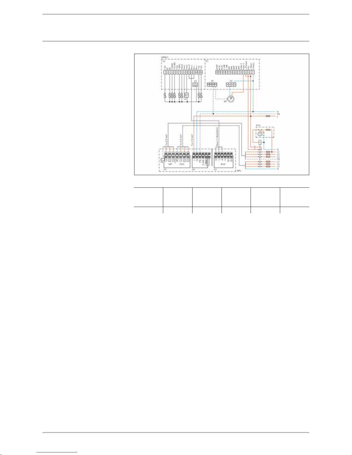
96 WWW.STIEBEL-ELTRON.COM
powEr SUpply wpl 33
Power supply
You may need to notify your local
power supply company of the heat
pump connection.
All electrical installation work,
particularly earthing measures, must
be carried out in accordance with
local and national regulations and
the requirements of your local power
supply company. The connection must
comply with the power connection
diagram. For this, also observe the
installation instructions for the heat
pump manager WPM II.
For external installation
Use only cables suitable for external
use to VDE 0100 [or local regulations].
Route such cables through a conduit
(protective pipe); entry into the heat
pump only from below.
For internal installation
Route the cables through the
installation aperture in the side of the
heat pump.
Electrical specification of the heat pump
Heat pump
Power
consumption
kW
Max. operating
current
A
Starting
current R start
A
Power cable
mm²
Fuse
protection
A
WPL 33 6.2 19.3 26 5 x 2.5 *
C 25A all poles
* Cable cross-section acc. to type of routing (observe VDE 0298-4 [or local regulations])
WPL
3/N/PE
230V ~ 50Hz
Domestic
electricity meter
Control phase L
w/o power-OFF
period
Control phase L´
with power-OFF
period
3/N/PE
400V ~ 50Hz
Heat pump
electricity meter
M1 = Circulation pump (max. 2A gl)
T(A) Outside temperature sensor N Power supply
B1 Temperature sensor heat pump flow L Power supply
B2
Temperature sensor heat pump return
EVU Enable signal
T (WW) Temperature sensor, DHW L UP Pumps L
T(2.WE) Temperature sensor for HS 2
Puffer1
Buffer primary pump
T (Q) Temperature sensor heat source
Puffer2
Buffer primary pump
T(MK) Temperature sensor, mixer circuit QKP Source circuit pump
Inpuls Pulse, heat meter HKP Heating circuit pump
Fern1 Remote control MKP Mixer circuit pump
Fern3 Remote control WW DHW primary pump
H BUS high ZKP DHW circulation pump
L BUS low 2.WE Heat source 2
– BUS ground M(A) Mixer open
+ BUS (not connected) M(Z) Mixer closed
T (S) Temperature sensor, solar/cooling KOKP Solar/cooling
T (K) Solar temperature sensor
Page 97

97WWW.STIEBEL-ELTRON.COM
notes
Page 98
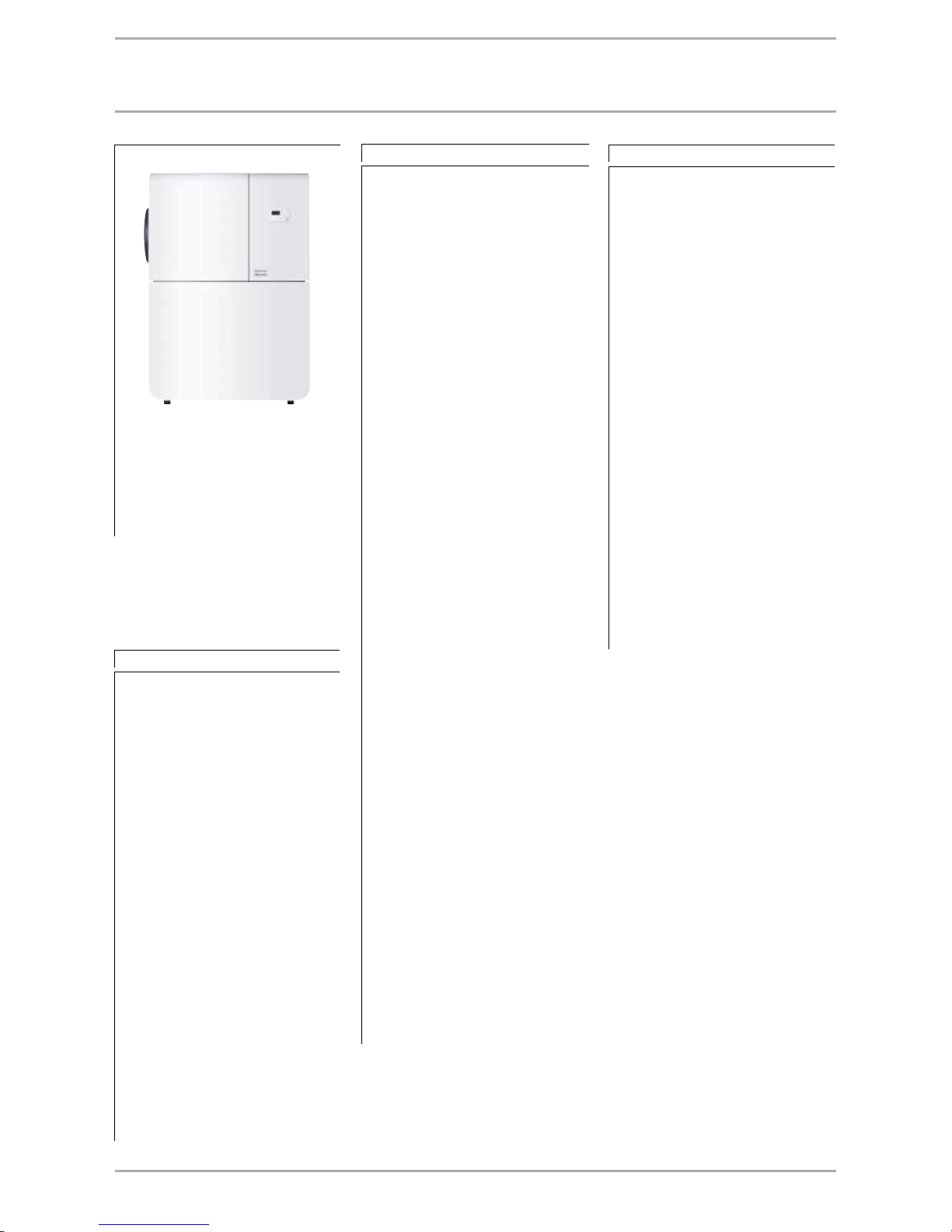
98 WWW.STIEBEL-ELTRON.COM
aIr | watEr HEat pUmp wpl 14 Ht
Function
Heat is extracted from the outside air
at temperatures ranging from +30°C
to –20 °C by the heat exchanger on
the air side (evaporator). Heating
water is heated to flow temperature
levels in the heat exchanger on
the water side (condenser) by this
extracted heat and additional heat
from the electrical power used by
the compressor. The heat pump
manager (WPM) matches the heat
pump heating output in two stages
to the actual heat demand. At air
temperatures below approx. +10 °C,
the humidity in the air precipitates as
hoarfrost on the evaporator fins. Any
hoarfrost is automatically defrosted.
Water created from this defrosting
collects in the defrost pan and is
drained off via a hose. The fan is
switched OFF and the heat pump
circuit is reversed to activate the
defrost cycle. The energy required for
defrosting is drawn from the heating
system. The heat pump automatically
reverts to heating mode at the end of
the defrost cycle.
Appliance description
High temperature air | water heat
pump for internal installation
with integral control unit WPM II,
circulation pump, patented special
heat pump cylinder, DHW diverter
valve, DCO active, expansion
vessel, safety valve and electric
booster heater for connection to
the heating system. Suitable for
mono-energetic or mode-mode
heating operation. Two inverter
compressors enable this appliance
to achieve flow temperatures up
to 75 °C in heat pump operation
alone; with the Stiebel Eltron DHW
cylinder, a DHW temperature >60°C
can be achieved. The evaporator is
defrosted by reversing the cycle. The
heat pump drive unit is equipped
with two inverter compressors one low temperature and one high
temperature - plus condenser,
evaporator and safety equipment,
such as a high/low pressure limiter.
Through the electronic expansion
valve, the coefficient of performance
is optimised over the entire
application range, and the heat pump
output is matched via the inverter
compressors to the actual heat
demand of the building to ensure an
optimum operation. The patented
special heat pump cylinder allows
operation without a separate buffer
cylinder. The integral control unit
enables a fully automatic, weathercompensated heating operation, DHW
heating priority, pasteurisation, a
heat-up program for screed drying
and connections for linking up to a PC
and modem. The heat pump is filled
with HCFC and CFC-free refrigerant
R407C.
At a glance
For fully automatic heating
water heating up to +75 °C flow
temperature
Suitable for underfloor and
radiator heating systems
Extracts energy from the outside
air, right down to -20 °C outside
temperature
Comprises all components
required for its function and
safety
Central control of the heating
system and safety functions
through the heat pump manager
(essential accessory)
Corrosion-protected, external
casing panels made from zincplated sheet steel with stove
enamelled finish; internal airways
made from corrosion-resistant
aluminium sheet
Compact design, therefore modest
space requirement
Contains non-combustible safety
refrigerant R407C
Output matching through two
inverter compressors
Page 99

99WWW.STIEBEL-ELTRON.COM
Type WPL 14 HT
Part no. single phase 22 93 44
Specification
Application limits WQA °C -20 to +30
Flow temperature WNA °C +15 to +75
Air flow rate WQA m³/h 3000
External static pressure differential Pa 100
Flow rate, heating side m³/h 1.00
Pressure diff., heating side hPa 190
Heating flow/return connection mm 22 plug-in connection
Air hose connection mm 500 round
Refrigerant R407C
Fill weight kg 4.4
Electrical details
Compressor power supply connection n x mm² 5 x 2.5 cable cross-section acc. to type of routing (observe VDE 0298-4)
Control cable n x mm² 5 x 1.5
BUS cable n x mm² J-Y (St) 2 x 2 x 0.8
Fuse - compressor A C 16A all poles
Control circuit fuse A C 16A
Protection EN 60529 IP 14 B
Voltage/frequency load V/Hz 3/PE ~ 400 V 50 Hz
Voltage/frequency control V/Hz 1/N/PE ~ 230 V / 50 Hz
Starting current A <30
Weight and dimensions
H x W x D mm 1734 x 1263 x 756
Weight kg 350
Other model characteristics
Corrosion protection zinc-plated
Compliant with safety regulations UVV/VDE/GS
Sound power level dB(A) 58/62
Sound pressure level at a distance of 5 m
dB(A) 43
Output details
Air temperature °C –7 +2 +10
Flow temperature °C +35 +35 +35
Heating output kW 8.3 7.0 8.0
Power consumption kW 3.2 2.2 2.0
COP ε 2.6 3.2 4.1
Temperature differential at A2/W35 K 5.0
aIr | watEr HEat pUmp wpl 14 Ht
Page 100

100 WWW.STIEBEL-ELTRON.COM
oUtpUt dEtaIlS wpl 14 Ht
Heating output (kW), power consumption (kW) and coefficient of performance ε
Heat
source
temp. °C
Heating output Power consumption COP
35 °C 45 °C 55 °C 35 °C 45 °C 55 °C 35 °C 45 °C 55 °C
kW kW kW kW kW kW ε ε ε
–15 12.2 12.4 12.3 5.7 6.1 6.7 2.1 2.0 1.8
–10 9.8 10.1 10.2 4.1 4.6 5.1 2.4 2.2 2.0
–5 8.0 8.3 8.7 3.0 3.5 4.0 2.7 2.4 2.2
0 7.3 7.4 7.8 2.4 2.9 3.6 3.0 2.5 2.2
+5 7.7 7.5 7.7 2.1 2.6 3.2 3.7 2.9 2.4
+10 8.0 8.2 7.8 2.0 2.4 2.9 4.0 3.4 2.7
+15 9.4 9.0 8.6 2.0 2.4 2.9 4.7 3.8 3.0
+20 10.5 10.1 9.7 2.0 2.4 2.9 5.3 4.8 3.3
Flow temperature 35 °C
Flow temperature 55 °C
Air inlet temperature °C
Heating output (kW)
 Loading...