


OPERATION AND INSTALLAT ION
Heat pump manager
» WPM 3
MITTWO CH 12.JUN 13
10:23 UHR
AUSSENTEMP ERATUR
WW-IS TTEMPERATUR
27,0 °C
35,0 °C
28,0 °C
RÜCKLAUFI STTEMPERATUR
ECO-BET RIEB

2 | WPM 3 www.stiebel-eltron.com
CONTENTS
OPERATION
1. General information _________________________________________3
1.1 Safety instructions ����������������������������������������������� 3
1.2 Other symbols in this documentation ����������������������� 3
1.3 Units of measurement ������������������������������������������ 3
2. Safety __________________________________________________________ 3
2.1 Intended use ������������������������������������������������������ 3
2.2 Safety instructions ����������������������������������������������� 3
2.3 Test symbols ������������������������������������������������������ 3
3. Appliance description _______________________________________4
3.1 Heat pump types ������������������������������������������������� 4
3.2 Accessories �������������������������������������������������������� 5
4. Operation _____________________________________________________6
4.1 Controls ������������������������������������������������������������ 6
4.2 Entering parameters �������������������������������������������� 7
4.3 Selecting operating modes ������������������������������������ 8
4.4 Picture symbols �������������������������������������������������� 9
5. Menu structure _______________________________________________9
5.1 INFO menu ������������������������������������������������������� 10
5.2 DIAGNOSIS menu �����������������������������������������������12
5.3 PROGRAMS menu ���������������������������������������������� 13
5.4 SETTINGS menu ������������������������������������������������� 16
6. Fault message ______________________________________________ 27
7. Maintenance and care _____________________________________ 27
INSTALLATION
8. Safety ________________________________________________________ 28
8.1 General safety instructions ����������������������������������� 28
8.2 Instructions, standards and regulations ������������������� 28
9. Standard delivery __________________________________________ 28
9.1 WPMW 3 (wall mounting) ������������������������������������� 28
9.2 WPMS 3 (control panel mounting) �������������������������� 28
10. Installation __________________________________________________ 28
10.1 Wall mounting WPMW 3���������������������������������������28
10.2 Control panel mounting WPMS 3 ���������������������������� 28
10.3 Programming unit ���������������������������������������������� 28
10.4 Electrical connection ������������������������������������������� 30
10.5 Sensor installation ���������������������������������������������� 33
10.6 FE7 remote control ��������������������������������������������� 34
10.7 FEK remote control ��������������������������������������������� 34
10.8 Internet Service Gateway ISG �������������������������������� 35
11. Commissioning _____________________________________________ 35
11.1 COMMISSIONING menu ���������������������������������������� 36
11.2 Setting parameters ��������������������������������������������� 40
12. Settings _____________________________________________________ 44
12.1 Standard settings ����������������������������������������������� 44
12.2 Settings made ��������������������������������������������������� 44
12.3 Appliance handover �������������������������������������������� 44
13. Troubleshooting ____________________________________________ 45
13.1 Fault display ����������������������������������������������������� 45
13.2 Fault list ����������������������������������������������������������46
13.3 Fault message – sensor break ������������������������������� 53
13.4 Heat pump-specific or hardware faults �������������������� 53
14. Specification ________________________________________________ 54
14.1 Details on energy consumption ������������������������������ 54
14.2 Data table �������������������������������������������������������� 54
GUARANTEE
ENVIRONMENT AND RECYCLING
OPERATION
General information
www.stiebel-eltron.com WPM 3| 3
OPERATION
1. General information
The chapter "Operation" is intended for appliance users and qualified contractors.
The chapter "Installation" is intended for qualified contractors.
Note
Read these instructions carefully before using the appliance and retain them for future reference.
Pass on the instructions to a new user if required.
1.1 Safety instructions
1.1.1 Structure of safety instructions
!
KEYWORD Type of risk
Here, possible consequences are listed that may result
from failure to observe the safety instructions.
Steps to prevent the risk are listed.
1.1.2 Symbols, type of risk
Symbol Type of risk
Injury
Electrocution
1.1.3 Keywords
KEYWORD Meaning
DANGER Failure to observe this information will result in serious
injury or death.
WARNING Failure to observe this information may result in serious
injury or death.
CAUTION Failure to observe this information may result in non-seri-
ous or minor injury.
1.2 Other symbols in this documentation
Note
General information is identified by the symbol shown
on the left.
Read these texts carefully.
Symbol Meaning
Material losses
(appliance damage, consequential losses and environmental pollution)
Appliance disposal
This symbol indicates that you have to do something. The ac-
tion you need to take is described step by step.
1.3 Units of measurement
Note
All measurements are given in mm unless stated otherwise.
2. Safety
2.1 Intended use
Observe the operating limits listed in chapter "Specification".
This appliance is intended for domestic use. It can be used safely
by untrained persons. The appliance can also be used in a non-domestic environment, e.g. in a small business, as long as it is used
in the same way.
Any other use beyond that described shall be deemed inappropriate. Observation of these instructions and of instructions for any
accessories used is also part of the correct use of this appliance.
2.2 Safety instructions
- The electrical installation and installation of the heating circuit must only be carried out by a recognised, qualified contractor or by our customer support engineers.
- The qualified contractor is responsible for adherence to all
currently applicable instructions during installation and
commissioning.
- Operate the appliance only when fully installed and with all
safety equipment fitted.
- Protect the appliance from dust and dirt ingress during
building work.
!
WARNING Injury
The appliance may be used by children aged 8 and up and
persons with reduced physical, sensory or mental capabilities or a lack of experience and know-how, provided
that they are supervised or they have been instructed on
how to use the appliance safely and have understood
the resulting risks. Children must never play with the
appliance. Children must never clean the appliance or
perform user maintenance unless they are supervised.
Note
Do not change any system-specific settings at the control
unit. Your contractor has set the control unit to match
the local conditions for your building and your individual
requirements. The system-specific parameters are protected by a code to prevent unintentional modifications.
The parameters that serve to adapt the appliance to your
personal requirements are not protected by a code.
2.3 Test symbols
See type plate on the appliance.
!
!

OPERATION
Appliance description
4 | WPM 3 www.stiebel-eltron.com
3. Appliance description
The second generation heat pump manager, also referred to as
WPM3, is responsible for the processes that control and regulate
all our heat pumps.
Connected heat pumps are controlled via the digital BUS connection that handles the bi-directional data exchange
Cascade control
Up to 6output stages can be controlled for heat generation.
The maximum permitted configuration for cascade control is subject to the type of heat pump you are using.
- 6 single compressor heat pumps
- 3 dual compressor heat pumps with identical compressors
- From the third connected heat pump upwards, an MSM must
be used to control the buffer charging pumps
Function overview
- The 4-wire data BUS enables rapid installation and system
extension using the MSM mixer module
- Control of a second heat source for DHW and heating
- 9 temperature inputs as set/actual value display
- Demand-dependent control of 7 different circulation pumps
- Input of the system and heat pump frost protection limits
- At least 10 h power reserve for the clock
- Automatic pump kick control
- Reset option
- Stored fault list with precise fault code indication on the display, including date and time
- Fast and precise fault diagnosis with system analysis, incl.
temperature scanning of heat pump and peripherals without
additional equipment.
- Default settings for time switch programs for all heating and
DHW circuits
- Solar differential controller
3.1 Heat pump types
Note
Heat pump type 5/5* cannot be connected directly to the heat pump manager.
Use an indoor unit with integral WPM 3 heat pump manager for these heat pumps.
The description of individual functions varies between the different heat pump types. The types of heat pump are therefore identified
in this document as HP type 1 to 5 and 1* to 5*.
Heat pumps with second internal heat source
HP type 1 HP type 2 HP type 3 HP type 4 HP type 5
WPL 13, 18, 23 cool WPL 10 A / I / IK WPL 15 A(C)S WPL 33 HT WPL 08, 12, 16 S Trend
WPL 13, 18, 23 E WPL 33 WPL 20 A(C) WPL 33, HT (S) WPL 22, 28 Trend
WPL 13, 20 basic WPL 25 A(S)
WPL 13, 20 A basic WPL 25 AC(S)
WPL 13, 18 S basic WPL 07, 09, 17 ACS classic
WPL 10 AC WPL 19 I(K), WPL 24 I(K)
WPL 10 ACS
Heat pumps with second external heat source
HP type 1* HP type 2* HP type 3* HP type 4* HP type 5*
WPL 13, 18, 23 cool WPF-M 10, 13, 16 WPL 15 A(C)S WPL 33 HT WPL 08, 12, 16 S Trend
WPL 13, 18, 23 E WPW-M 13, 18, 22 WPL 20 A(C) WPL 33, HT (S) WPL 22, 28 Trend
WPL 13, 20 basic WPF 20, 27, 35, 40, 52, 66 WPL 25 A(S)
WPL 13, 20 A basic WPF 27 HT WPL 25 AC(S)
WPL 13, 18 S basic WPL 10 A / I / IK WPL 07, 09, 17 ACS classic
WPL 10 AC WPL 33 WPL 19 I(K), WPL 24 I(K)
WPL 10 ACS
WPL 34, 47, 57
OPERATION
Appliance description
www.stiebel-eltron.com WPM 3| 5
3.2 Accessories
FE7 remote control
PIC00000609
The FE7 remote control allows you to:
- Change the set room temperature for heating by ±5°C, for
heating circuit1 or heating circuit2.
- Change the operating mode.
The FE7 remote control features the following controls:
- Rotary selector for changing the set room temperature
- Rotary selector with the following positions
-
Automatic mode
-
Constant setback mode
-
Constant day mode
Note
The remote control is only effective in the automatic mode
of the heat pump manager.
FEK remote control
PIC00000704
The FEK remote control allows you to:
- Change the set room temperature for heating by ±5°C, for
heating circuit1 or heating circuit2.
- Change the operating mode.
The device features the following controls:
- Rotary selector for changing the set room temperature
- “Away” button
- “Info” button
- Button for selecting the following operating modes:
-
Standby mode
-
Automatic mode
-
Constant day mode
-
Constant setback mode
Note
If the FEK is pre-selected for a specific heating circuit,
the heating curve, room temperature and heating program parameters are not shown at the WPM3 heat pump
manager.
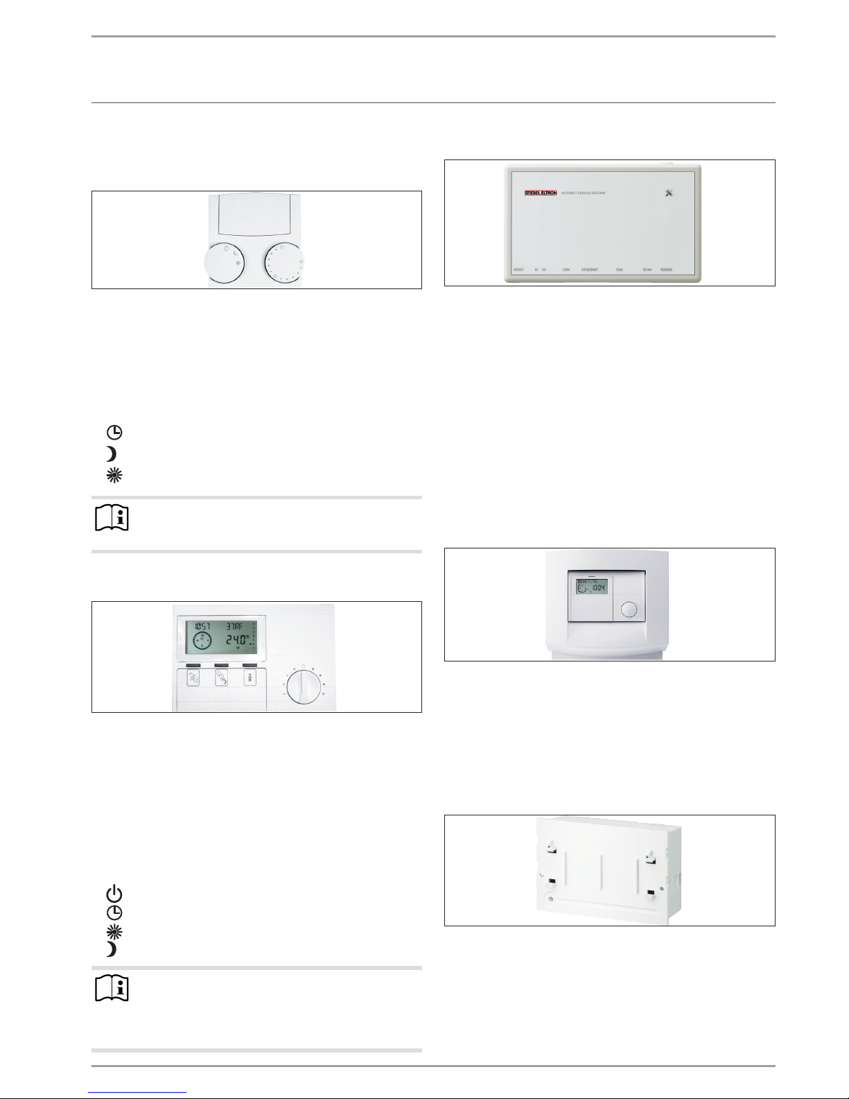
Internet Service Gateway (ISG)
PIC00001002
The Internet Service Gateway (ISG) is an Ethernet gateway in a
wall mounting enclosure and is connected into the LAN (local
area network).
It enables the convenient operation, adjustment and checking of
heat pump system data via the browser of a computer, laptop or
tablet in the local home network.
If required by the customer, appliance data can be automatically
transmitted to the appliance manufacturer’s Servicewelt portal
via the internet.
Via services, you can access additional options such as system
operation on the go with a smartphone as well as remote setting
of parameters and remote diagnosis, etc.
You can find the current services on our homepage.
Mixer module MSMW
PIC00000599
The MSM is an extension module for the WPM 3 which makes
additional functions available.
The MSM can also be used as an independent mixer control. In
this case, an outside temperature sensor has to be connected to
the MSM as it cannot communicate with the WPM.
The MSM is operated in the same way as the WPM II.
MSMS 3 mixer and swimming pool module
PIC00005250
The MSM is a control panel module for the WPMS3 which makes
additional functions available. The module does not have its own
programming unit; it is operated via the WPM3. The menus are
extended accordingly.
OPERATION
Operation
6 | WPM 3 www.stiebel-eltron.com
4. Operation
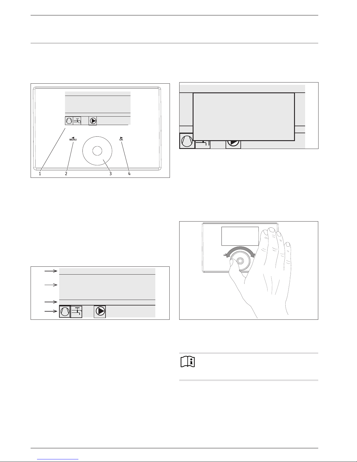
4.1 Controls
OKMENU
D0000064711
WEDNESDAY 12JUN 13 10:23 TIME
OUTSIDE TEMPERATURE
ACTUAL WW TEMPERATURE
27. 0 °C
35.0 °C
28.0 °C
ACTUAL RETURN TEMPERATURE
ECO MODE
1 32 4
1 Display
2 MENU key
3 Scroll wheel
4 OK key
You control the system with the programming unit of the heat
pump manager. Use the scroll wheel and the MENU and OK keys
to navigate through the menu structure.
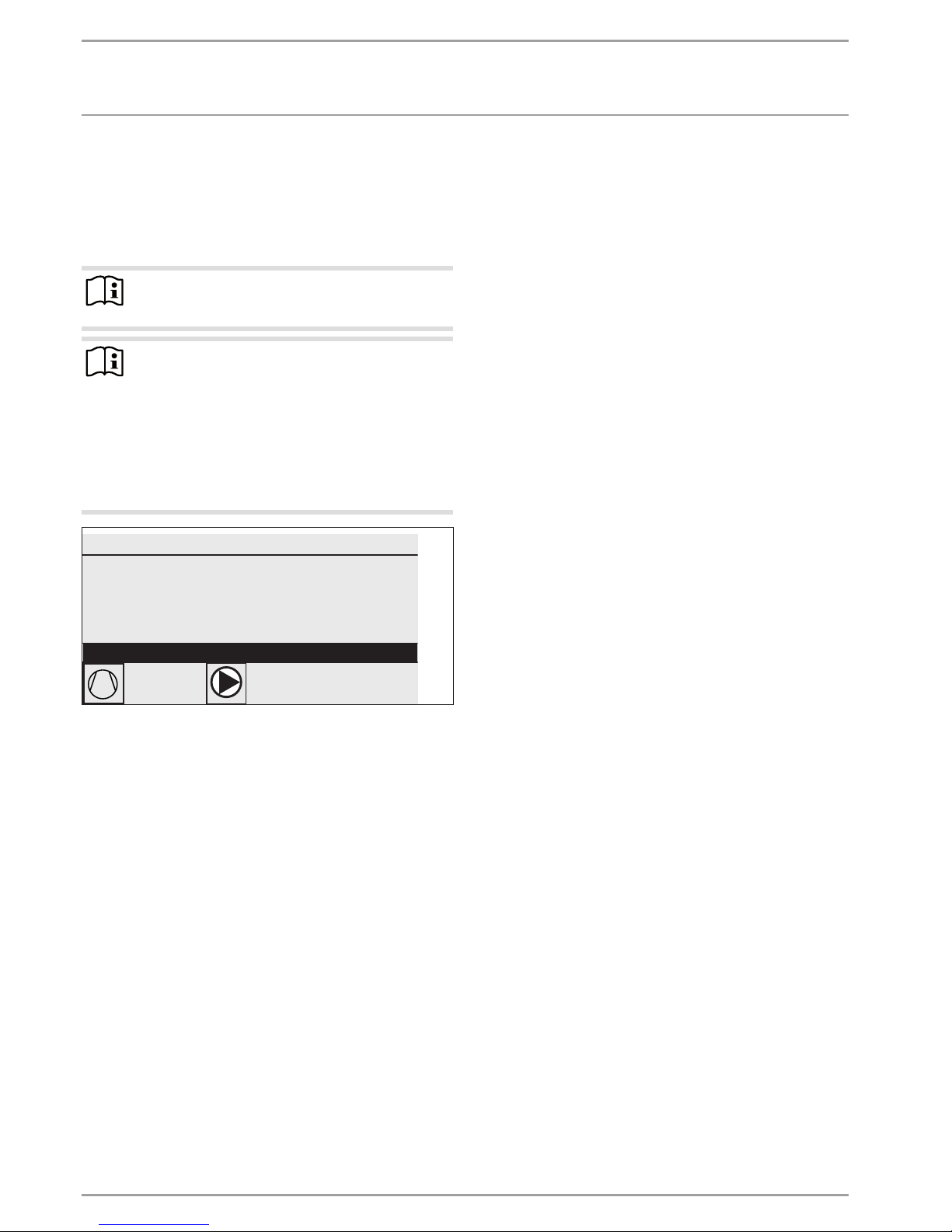
4.1.1 Display
The programming unit display shows the current system status
and provides messages and information.
Start screen
WEDNESDAY 12JUN 14 10:23 TIME
OUTSIDE TEMPERATURE
ACTUAL WW TEMPERATURE
27.0 °C
35.0 °C
28.0 °C
ACTUAL RETURN TEMPERATURE
ECO MODE
26�04�01�0292
1
2
3
4
1 Date and time
2 Temperature display
3 Operating mode
4 System status picture symbols
The start screen is divided into four sections. The top field displays
the date and time. The field below displays the outside temperature along with the actual DHW temperature and the actual return
temperature. The third section is for selecting and displaying the
operating modes. In the fourth section, picture symbols indicate
the current system status.
Activating
If the scroll wheel and keys are not used for 5minutes, the programming unit is locked.
WEDNESDAY 12JUN 14 10:23 TIME
OUTSIDE TEMPERATURE
ACTUAL WW TEMPERATURE
27.0 °C
35.0 °C
28.0 °C
ACTUAL RETURN TEMPERATURE
ECO MODE
To activate please
press MENU
for 3 seconds.
26�04�01�0292
Press MENU for three seconds to activate the programming
unit.
Selection indicator
A selection indicator shows the current position within the menu
structure at all times. The currently selected menu item is indicated by a dark background. The current menu level is indicated
at the top of the display.
4.1.2 Touch wheel
D0000064710
The scroll wheel consists of a touch-sensitive sensor. There is a
key to the left and another to the right of it. All required appliance
functions are controlled and checked with the scroll wheel and
the keys.
Note Sensor responsiveness
If you have gloves on, have wet hands or the programming unit is damp, this impedes the recognition of your
touch and the execution of the action you require.
Your contractor can set the sensitivity to touch under SETTINGS/
GENERAL using the TOUCH SENSITIVITY parameter.
OPERATION
Operation
www.stiebel-eltron.com WPM 3| 7
Circular movement
Move one finger clockwise over the scroll wheel to move the selection indicator downwards or to the right in the list, depending
on how the menu items are arranged. Scrolling anti-clockwise
moves the selection indicator to the left or upwards in the list.
Alongside navigation within the menu structure, the scroll wheel
is also used to set parameters. Scrolling clockwise increases the
values. Scrolling anti-clockwise decreases the values.
4.1.3 Keys
Note
Press the keys only briefly to initiate the required action.
If a key is touched for too long, the programming unit
does not respond.
MENU key
The MENU key has two functions:
- On the start screen, touch the MENU key to navigate to the
first of the 5 menu structure levels.
- Touching the MENU key while in the menu structure will return you to the previous menu level.
OK key
The OK key has four functions:
- On the start screen, touching the OK key will activate the
required operating mode previously selected with the scroll
wheel.
- Within the menu structure, touching the OK key confirms the
selected menu item and takes you to the next lower menu
level.
- If you are already at parameter level, touching the OK key
saves the currently set parameter.
- At every menu level, you will see the entry BACK. Selecting
BACK takes you to the next higher menu level.
If there is no user action for more than five minutes, no scrolling
and neither
MENU nor OK are pressed, the programming unit
display automatically reverts to the start screen.
Any recent parameter changes which had not yet been confirmed
with OK are lost. The parameters retain the values previously
saved.
4.1.4 Contractor access
Note
Some menu items are protected by a code and can only
be accessed and adjusted by a qualified contractor.
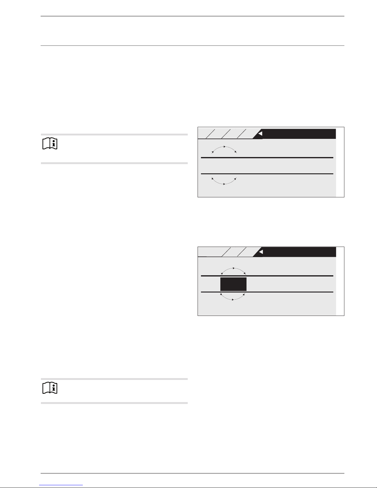
4.2 Entering parameters
Parameters are changed by scrolling with the scroll wheel. To save
the new value, touch OK.
If you want to cancel the entry, touch
MENU. The parameter re-
tains the previously saved value.
Example 1
Adjusting the set room temperature.
+
21.7
-
MAIN MENU
SETTINGS
°C SET ROOM TEMP COMFORT
26�04�01�0347
HEATI NG HK1
HEATING CIRCUIT 1
SET ROOM TEMP CO
21
To enter set temperatures, a number surrounded by a circle appears on the display. This indicates that you can change the value
by scrolling with the scroll wheel.
Example 2
Setting the time and date.
15.
09 08:23
DAY MONTH YEAR Hour Minute
Jun
26�04�01�0296
MAIN MENU
SETTINGS
GENERAL
TIME / DATE
SET CLOCK
14
On activation, the selection indicator is over the position MONTH.
Confirm with OK. Set the current month with the scroll wheel and
confirm with OK. A calendar page is displayed. Move the indicated
field to the required day using the scroll wheel and confirm with
OK. The new value is saved when you confirm with OK. Set the
year, hours and minutes the same way.
OPERATION
Operation
8 | WPM 3 www.stiebel-eltron.com
4.3 Selecting operating modes
When the start screen is activated, the current operating mode
is displayed. If you want to select another operating mode, scroll
with the scroll wheel. This takes you through the list of possible
operating modes. The current choice (list entry) is shown in the
shaded selection field.
Note
To change the appliance to this new operating mode,
confirm with OK.
Note
If the selection field shows “POWER-OFF” behind the operating mode, then the heat pump will not heat or cool
during the blocking time.
The compressor and the internal electric reheating stages are switched off. If a buffer cylinder is installed, the
heating circuit pumps will continue running.
One external heat source can be configured for the blocking time (see chapter “SETTINGS / HEATING / EXTERNAL
HEAT SOURCE / BLOCKING TIME EVU”).
WEDNESDAY 12JUN 14 10:23 TIME
OUTSIDE TEMPERATURE
ACTUAL WW TEMPERATURE
27.0 °C
35.0 °C
28.0 °C
ACTUAL RETURN TEMPERATURE
26�04�01�0292
ECO MODE
Since navigation to a new operating mode is always made from the
currently enabled mode, you may need to scroll in an anti-clockwise direction. All operating modes, apart from DHW mode, apply
to both heating and DHW.
Standby mode
Frost protection is activated for heating and DHW mode. The set
DHW value is fixed at 10°C, the set heating flow value is calculated
based on a set room value of 5°C.
Application: During prolonged periods of absence, e.g. holidays.
Programmed operation
Heating according to the time switch program (applies to heating circuit1 and heating circuit2). Changeover between comfort
temperature and ECO temperature.
DHW heating according to the time switch program; changeover
between comfort temperature and ECO temperature.
The remote control is only effective in this operating mode.
Application: When DHW and heating are required.
Comfort mode
The heating circuit (HC) is constantly held at the comfort temperature (HC1 and HC2). DHW heating according to time switch
program.
Application: Low energy houses without setback mode.
ECO mode
The heating circuit is constantly held at the ECO temperature (applicable to HC1 and HC2). DHW heating according to time switch
program.
Application: During weekends away.
DHW mode
DHW heating according to time switch program. If a time program
is active, the water inside the DHW cylinder is heated to the set
comfort temperature. At all other times, the water is heated to
the set ECO temperature. Frost protection is activated for heating
mode.
Application: The heating season has ended; only DHW should be
provided (summer mode).
Emergency operation
This setting activates the emergency operation.
In heat pumps with an integral 2nd heat source, the NHZ stages (electric reheating stages) of the electric emergency/booster
heater take over DHW and central heating irrespective of the dual
mode changeover point.
For heat pumps with an external 2nd heat source, the external
heat source for DHW or central heating must be set to ON under
SETTINGS / HEATING or DHW. Only then can the operating mode
be selected. The external heat source then takes over operation
for the DHW or central heating function, irrespective of the dual
mode changeover point.
OPERATION
Menu structure
www.stiebel-eltron.com WPM 3| 9
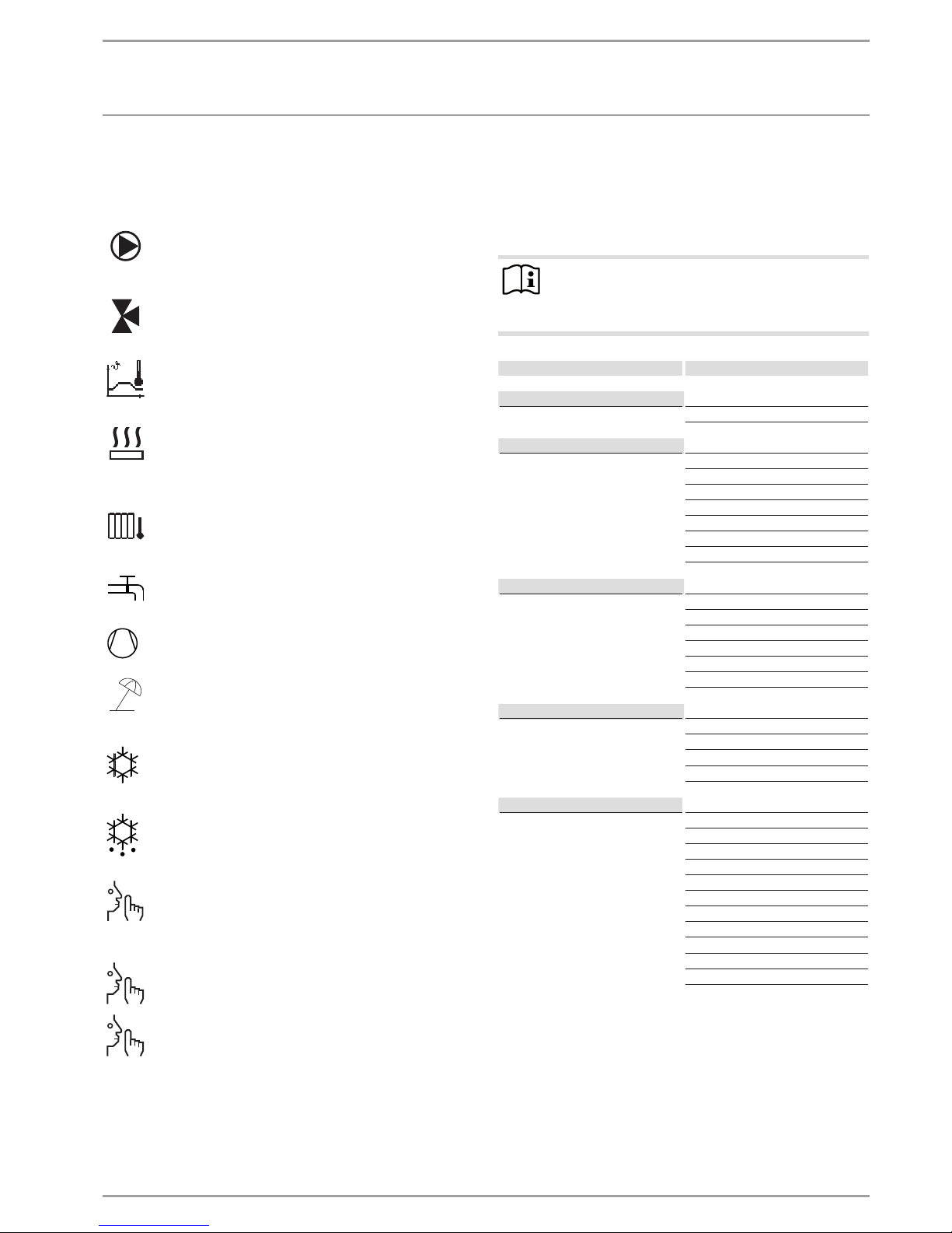
4.4 Picture symbols
At the lower edge of the display, symbols provide information
about the current operating status of the heat pump.
Heating circuit pump
The pump symbol is displayed when a heating circuit
pump is running.
Mixer circuit pump
The mixer symbol is displayed when a mixer circuit pump
is running.
Heat-up program
This symbol is displayed when the heat-up program is
running.
Electric emergency/booster heater
The electric emergency/booster heater has started up.
This occurs, for example, when the outside temperature
has fallen below the dual mode point.
Heating
The heating symbol is displayed when the heat pump is
in heating mode.
DHW heating
This symbol indicates that the heat pump is heating DHW.
Compressor
The symbol is displayed when the compressor is running.
Summer mode
The symbol is displayed when the heat pump is in summer mode.
Cooling
The symbol is displayed when the heat pump is in cooling
mode.
Defrost
The symbol is displayed when the heat pump is in defrost
mode.
Silent mode
Reduced noise mode
Silent mode is enabled. The associated time programs
determine activation of the fan or compressor throttle.
1
Silent mode 1
The fan and / or compressor run with reduced output.
2
Silent mode 2
Compressor and fan are stopped. Heat source 2 takes
over heating.
Note: This operating mode can result in higher operating
costs.
5. Menu structure
After activating the programming unit, you can use the touch
wheel to select alternative operating modes or use the menu key
to jump to a level from which you can navigate to a specific appliance parameter.
Note
Not all appliance parameters and values are displayed
in the different menus, depending on which heat pump
type is connected.
Level 1 Level 2
INFO SYSTEM
HEAT PUMP 1-6
DIAGNOSIS SYSTEM STATUS
HEAT PUMP STATUS 1-6
HEAT PUMP ANALYSIS 1-6
SYSTEM
INTERNAL CALCULATION
FAULT LIST
RELAY TEST SYSTEM
RELAY TEST HEAT PUMP 1-6
PROGRAMS HEATING PROGRAM
DHW PROGRAM
PARTY PROGRAM
HOLIDAY PROGRAM
HEAT-UP PROGRAM
SILENT PROGRAM 1
SILENT PROGRAM 2
SETTINGS GENERAL
HEATING
DHW
COOLING
SOLAR
COMMISSIONING ENTER CODE
LANGUAGE
SOURCE
HEATING
DHW
COMPRESSOR
SILENT MODE
EMERGENCY OPERATION
HEAT PUMP RESET
FAULT LIST RESET
SYSTEM RESET
SENSOR CALIBRATION

OPERATION
Menu structure
10 | WPM 3 www.stiebel-eltron.com
5.1 INFO menu
In the INFO menu you can compare the set and actual values for
temperatures, flow rates and pressures of the heating system and
the heat pump.
Note
Please note that actual and set values can only be displayed if the appropriate sensors are connected.
5.1.1 INFO SYSTEM
Level 3
ROOM TEMPERATURE
ACTUAL TEMPERATURE FE7
Actual room temperature for heating circuit 1 (HC1) or heating circuit 2 (HC2)
(is only displayed if the FE7 remote control is connected)
°C
SET TEMPERATURE FE7
Set room temperature for heating circuit 1 (HC1) or heating circuit
2 (HC2)
(only displayed if the FE7 remote control is connected)
°C
ACTUAL TEMPERATURE FEK
Actual room temperature for heating circuit 1 or heating circuit 2
(is only displayed if the FEK remote control is connected)
°C
SET TEMPERATURE FEK
Set room temperature for heating circuit 1 or heating circuit 2
(is only displayed if the FE7 remote control is connected)
°C
RELATIVE HUMIDITY %
DEW POINT TEMPERATURE
Dew point temperature (is only displayed if the FEK remote control
is connected)
°C
HEAT ING
OUTSIDE TEMPERATURE °C
ACTUAL TEMPERATURE HK 1
Actual heating circuit temperature, heating circuit 1
°C
SET TEMPERATURE HK 1
Set heating circuit temperature, heating circuit 1 (HC1). With fixed
value control, the fixed temperature is displayed.
°C
ACTUAL TEMPERATURE HK 2
Actual heating circuit temperature, heating circuit 2
°C
SET TEMPERATURE HK 2
Set heating circuit temperature, heating circuit 1 (HK1). With fixed
value control, the fixed temperature is displayed.
°C
ACTUAL FLOW TEMPERATURE HP
Actual heat pump flow temperature
°C
ACTUAL FLOW TEMPERATURE NHZ
Reheating stages, actual flow temperature
°C
ACTUAL RETURN TEMPERATURE WP °C
SET FIXED TEMPERATURE °C
ACTUAL BUFFER TEMPERATURE
Actual buffer cylinder temperature
°C
SET BUFFER TEMPERATURE
Set buffer cylinder temperature
°C
HEATING PRESSURE bar
FLOW R ATE l/min
SYSTEM FROST PROTECTION °C
DHW
ACTUAL TEMPERATURE
Actual DHW temperature
°C
SET TEMPERATURE
Set DHW temperature
°C
FLOW R ATE l/min
Level 3
COOLING
ACTUAL TEMPERATURE FAN °C
SET TEMPERATURE FAN °C
ACTUAL TEMPERATURE AREA °C
SET TEMPERATURE AREA °C
SOLAR
COLLECTOR TEMPERATURE °C
CYLINDER TEMPERATURE °C
RUNTIME Hours
EXTERNAL HEAT SOURCE
ACTUAL TEMPERATURE °C
SET TEMPERATURE °C
DUAL MODE TEMP HZG
Heating dual mode point
°C
APPLICATION LIMIT HZG
Heating application limit
°C
DUAL MODE TEMP DHW
DHW dual mode point
°C
APPLICATION LIMIT DHW
DHW application limit
°C
RUNTIME Hours
ELECTR IC REHEAT ING
DUAL MODE TEMP HZG
Heating dual mode point
°C
APPLICATION LIMIT HZG
Heating application limit
°C
DUAL MODE TEMP DHW
DHW dual mode point
°C
APPLICATION LIMIT DHW
DHW application limit
°C
SOURCE
SOURCE TEMPERATURE °C
MIN SOURCE TEMPERATURE °C

OPERATION
Menu structure
www.stiebel-eltron.com WPM 3| 11
5.1.2 INFO HEAT PUMP 1-6
Note
The power consumption is calculated on the basis of refrigerant circuit pressure. This calculation is inappropriate for billing purposes. Together with the amount of heat
it is used for a rough energy statement.
Level 3
PROCESS DATA
RETURN TEMPERATURE °C
FLOW TEMPERATURE °C
FROST PROTECTION TEMP °C
OUTSIDE TEMPERATURE °C
EXHAUST AIR TEMPERATURE °C
EVAPOR ATOR TEMPER AT UR E °C
RECUPERATOR TEMPERATURE °C
COMP SUCTION GAS TEMP °C
COMP SUCTION GAS TEMP ND °C
COMP SUCTION GAS TEMP HD °C
INTERMEDIATE INJ TEMP °C
HOT GAS TEMPERATURE °C
CONDENSER TEMPERATURE °C
OIL SUMP TEMPERATURE °C
LOW PRESSURE bar
MEAN PRESSURE bar
HIGH PRESSURE bar
DIFF PRESSURE VOLT INPUT V
DIFFERENTIAL PRESSURE mbar
WP WATER FLOW RATE l/min
INVERTER CURRENT ND A
INVERTER CURRENT HD A
INVERTER CURRENT A
INVERTER VOLTAGE V
SPEED ND Hz
SET SPEED ND Hz
SPEED HD Hz
SET SPEED HD Hz
ACTUAL COMPRESSOR SPEED Hz
SET COMPRESSOR SPEED Hz
REL FAN RATE %
ACTUAL FAN SPEED Hz
SET FAN SPEED Hz
EVAPORATOR INLET TEMP. °C
AMOUNT OF HEAT
VD HEATING DAY
Amount of compressor heat generated in heating mode since 00:00
of the current day.
kWh
VD HEATING TOTAL
Total amount of compressor heat generated in heating mode.
MWh
VD DHW DAY
Amount of compressor heat generated in DHW mode since 00:00 of
the current day.
kWh
VD DHW TOTAL
Total amount of compressor heat generated in DHW mode.
MWh
NHZ HEATING TOTAL
Total amount of booster heat generated in heating mode.
MWh
NHZ DHW TOTAL
Total amount of booster heat generated in DHW mode.
MWh
Level 3
POWER CONSUMP TION
VD HEATING DAY
Amount of electric compressor output in heating mode since 00:00
of the current day.
kWh
VD HEATING TOTAL
Total amount of electric compressor output in heating mode.
MWh
VD DHW DAY
Amount of electric compressor output in DHW mode since 00:00 of
the current day.
kWh
VD DHW TOTAL
Total amount of electric compressor output in DHW mode.
MWh
RUNT IME
VD HEATING
Runtime of compressor in heating mode.
Hours
VD 1 HEATING
Runtime of compressor 1 in heating mode.
Hours
VD 2 HEATING
Runtime of compressor 2 in heating mode.
Hours
VD 1/2 HEATING
Runtime of compressor 1 and 2 in heating mode.
Hours
VD DHW
Runtime of compressor in DHW mode.
Hours
VD 1 DHW
Runtime of compressor 1 in DHW mode.
Hours
VD 2 DHW
Runtime of compressor 2 in DHW mode.
Hours
VD 1/2 DHW
Runtime of compressor 1 and 2 in DHW mode.
Hours
VD COOLING
Runtime of compressor in cooling mode.
Hours
VD DEFROST
Runtime of compressor in defrost mode.
Hours
VD 1 DEFROST
Runtime of compressor 1 in defrost mode.
Hours
VD 2 DEFROST
Runtime of compressor 2 in defrost mode.
Hours
NHZ 1
Runtime of electric emergency/booster heater in booster stage 1.
Hours
NHZ 2
Runtime of electric emergency/booster heater in booster stage 2.
Hours
NHZ 1/2
Runtime of electric emergency/booster heater in booster stages 1
and 2.
Hours
DEFROST TIME Minutes
DEFROST STARTS
STAR TS
COMPRESSOR
COMPRESSOR 1
COMPRESSOR 2

OPERATION
Menu structure
12 | WPM 3 www.stiebel-eltron.com
5.2 DIAGNOSIS menu
For heating system and heat pump troubleshooting and analysis,
you can call up all important process data and BUS subscribers
under DIAGNOSIS and carry out a relay test.
Note
Menu item RELAY TEST SYSTEM is protected by a code
and can only be accessed by a qualified contractor.
Level 2 Level 3
SYSTEM S TATUS
BUFFER CHARGING PUMP
DHW VALVE
HEATING CIRCUIT PUMP
MIXER PUMP
MIXER OPEN
MIXER CLOSE
SOURCE PUMP
COOLING MODE
BUFFER CHARGING PUMP 1
BUFFER CHARGING PUMP 2
BUFFER CHARGING PUMP 3 - 6
DHW CHARGING PUMP
HEAT SOURCE 2
DHW CIRCULATION PUMP
SOLAR CIRCUIT PUMP
NHZ 1
NHZ 2
NHZ 1/2
POWER-OFF
HEAT PUMP STATUS 1 - 6
REMAINING IDLE TIME
COMPRESSOR
COMPRESSOR ND
COMPRESSOR HD
COMPRESSOR 1
COMPRESSOR 2
NHZ 1
NHZ 2
NHZ 1/2
DEFROST VALVE
PRESSURE COMPENSATION
OIL COMPENSATION
OIL SUMP
FAN
RIBBON HEATER
EXTERNAL COMPRESSOR ON
EXTERNAL FAULT
HD LIMITER
HD/TEMPERATURE MONITOR
DEFROST SIGNAL
CENTRAL INPUT
INVERTER POWER SUPPLY
FAULT
FORCED HEATING
COOLING MODE
HEAT PUMP ANALYSIS 1-6
SET SUPERHEATING
ACTUAL SUPERHEATING V
CONTROL DEVIATION
P FACTOR
I FACTOR
D FACTOR
PRE-CTRL OPENING EXV
Level 2 Level 3
OPENING EXV
SET SUPERHTG SG V HD
ACTUAL SUPERHTG SG V HD
P FACTOR V-HD
I FACTOR V-HD
D FACTOR V-HD
SET SUPERHEATING SG V-ZE
ACTUAL SUPERHEATING SG V-ZE
P FACTOR V-ZE
I FACTOR V-ZE
D FACTOR V-ZE
V OPENING DEGREE EXV ZE
OPENING EXV ZE
SUPERCOOLING COND
ACTUAL SUPERHEATING REK
INTERMEDIATE INJ PRESSURE
ACTUAL SUPERHEATING ZE
AMBIENT TEMP. INVERTER
TEMP. INV. COMPRESSOR
TEMPERATURE INV. FAN
MOTOR CURRENT
BYPASS VALVE OPENING LVL
SYSTEM
BUS SUBSCRIBER
HEAT PUMP TYPE
INTERNAL CALCULATION
INTERVAL
LIVE STAGES
FAULT L IST
RELAY TEST SYSTEM
DHW CIRCULATION PUMP
BUFFER CHARGING PUMP 1
BUFFER CHARGING PUMP 2
DHW CHARGING PUMP
HEATING CIRCUIT PUMP
HEAT SOURCE 2
WE 2 MIN OUTPUT
WE 2 MAX OUTPUT
MIXER OPEN
MIXER CLOSE
MIXER PUMP
SOURCE PUMP
SOLAR CIRCUIT PUMP
COOLING MODE
DRAIN HYD
NHZ 1
NHZ 2
NHZ 3
RELAY TEST HEAT PUMP 1-6
DEFROST
FAN
NHZ 1
NHZ 2
OIL SUMP
COMPRESSOR
STEPPER MOTOR PHASE 1
STEPPER MOTOR PHASE 2
STEPPER MOTOR PHASE 3
STEPPER MOTOR PHASE 4
STEPPER MOTOR PHASE 1 ZE
STEPPER MOTOR PHASE 2 ZE
STEPPER MOTOR PHASE 3 ZE
STEPPER MOTOR PHASE 4 ZE
OPERATION
Menu structure
www.stiebel-eltron.com WPM 3| 13
Level 2 Level 3
RIBBON HEATER
EXTERNAL COMPRESSOR ON
EXTERNAL FAULT
EX VALVE CENTRE POSITION
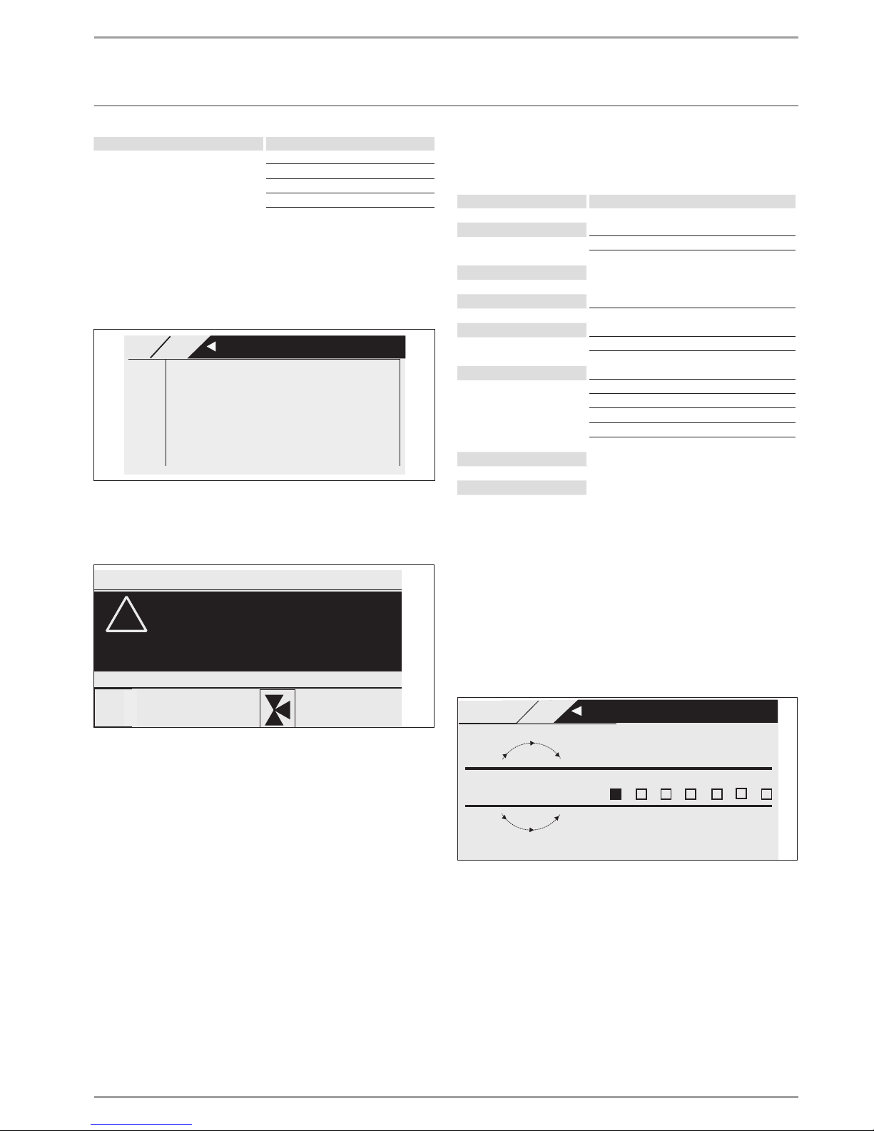
5.2.1 Fault list
The fault list provides an overview of the faults most recently
registered by the appliance. The fault list contains up to 20 fault
messages. The display, however, can show only 2. Scroll with the
scroll wheel to access the other entries in the fault list.
MAIN MENUDIAGNOSIS
FAULT L IST 1/1
01. SENSOR BREAK E 71
10:26 14 JUN 14
02. MIN SOURCE
17:45 25 JUN 13
5.2.2 Fault message
If the appliance registers a fault, this is clearly displayed with the
message shown below.
COMFORT MODE
!
FAULT
SENSOR BREAK E 71
TUESDAY 14JUN 14 16:27 TIME
If more than one fault occurs, the most recent fault is always
shown. Notify your qualified contractor.
5.2.3 Relay test
All relay outputs of the controller and heat pump can be individually switched from here.
5.3 PROGRAMS menu
All times for the heating, DHW, holiday and party modes can be
adjusted here. In addition, the heat-up program can be started.
Level 2 Level 3
HEAT ING PRO GRAM
HEATING CIRCUIT 1
HEATING CIRCUIT 2
DHW PROGR AM
PART Y PROGRAM
HOURS
HOL IDAY PROGRAM
HOLIDAYS BEGINNING
HOLIDAYS ENDING
HEAT-UP PRO GR AM
LOW END TEMPERATURE
DURATION BASE TEMP
MAXIMUM TEMPERATURE
MAX TEMPERATURE DURATION
RISE PER DAY
SILENT PROGR AM 1
SILENT PROGR AM 2
5.3.1 HEATING PROGRAM
In menu item HEATING PROGRAM you can determine when and
how often the appliance heats to the set comfort values for heating
circuit1 and heating circuit2. At all other times, the appliance
heats to the set ECO value. You can adjust the set values under
menu item SETTINGS / HEATING / HEATING CIRCUIT1 or HEATING CIRCUIT2. Below is an explanation of how to define a time
program.
First, select the days on which you want to enable the HEATING
function:
+
-
26�04�01�0301
Monday
Mon
MAIN MENU
PROGRAMS
HEATING PROGRAM
HEATING CIRCUIT 1
You can set your heating system as follows:
- For each individual day of the week (Monday - Sunday)
- Monday to Friday (Mon - Fri)
- Saturday and Sunday (Sat - Sun)
- the whole week (Mon - Sun)
Monday is initially offered.
Scroll with the scroll wheel to select another day or group of
days.
Confirm your selection with OK.
You can now set three switching time pairs. The three switching
time pairs are shown on the display, to the right of the clock. A

OPERATION
Menu structure
14 | WPM 3 www.stiebel-eltron.com
switching time pair comprises the start time and end point, at
which the appliance returns to its previous state.
07:00 - 20:00
- -:- - - - -:- -
- -:- - - - -:- -
26�04�01�0299
MONDAY
MAIN MENU
PROGRAMS
HEATING PROGRAM
HEATING CIRCUIT 1
In this example, only one switching time pair has so far been
programmed. For switching time pairs 2 and 3, short dashes are
displayed instead of times. These switching time pairs are still
empty. Select one of the free switching time pairs with OK to reach
the area where you can set the associated start and end time.
Pressing OK brings up the display shown below. Set the required
time with the scroll wheel.
End
- -:- -
- -:- -
TIME TIME
Start
26�04�01�0302
MAIN MENU
PROGRAMS
HEATING PROGRAM
HEATING CIRCUIT 1
Times can be entered in intervals of 15 minutes. You can set 16:30
or 16:45 h, but not 16:37 h. Confirm your entry with OK.
Periods around midnight
Assume, for example, you want heating mode to be enabled from
22:00 h for four hours every Wednesday evening. This means the
period does not expire until the next day, Thursday, at 02:00 h.
However, since the day ends at 00:00h, two switching time pairs
are necessary for the required program. First, program the period
22:00 to 00:00 h for Wednesday, then 00:00 to 02:00 h for Thursday.
5.3.2 DHW PROGRAM
In menu item DHW PROGRAM you can determine the times during
which DHW heating to the set comfort value should take place.
At all other times, DHW is heated to the set ECO value. You can
adjust the set values under menu item SETTINGS / DHW / DHW
TEMPERATURES. The DHW circulation output is also switched in
line with the times programmed here.
You can set your DHW heating as follows:
- For each individual day of the week (Monday - Sunday)
- Monday to Friday (Mon - Fri)
- Saturday and Sunday (Sat - Sun)
- the whole week (Mon - Sun)
You can set three switching time pairs for each of these options.
Exception: If you want to heat DHW from 22:00 h until 06:00 h the
following day you will need two switching time pairs.
Example:
You would like to heat DHW twice daily, e.g. from 22:00 h until
06:00 h the following day, and then from 08:00 h until 09:00 h.
As the day begins at 00:00 h, programming for this example must
again start at 00:00 h.
- The first switching time pair runs from 00:00 h until 06:00 h.
- The second switching time pair runs from 08:00 h until
09:00h.
- The third switching time pair runs from 22:00 h until 24:00 h.
5.3.3 PARTY PROGRAM
In the party program you can extend the comfort mode for heating
by a few hours.
5.3.4 HOLIDAY PROGRAM
In the holiday program, the heat pump system runs in ECO mode
and frost protection for DHW heating is enabled.
For both the start and end of the holiday, enter the year, month
and day. The start time is 0:00h on the first day of the holiday. The
end time is 24:00h on the day the holiday ends. After the holiday
period has expired, the heat pump system switches back to the
previous heating and DHW program.
5.3.5 HEAT-UP PROGRAM
Note
Menu item HEAT-UP PROGRAM is protected by a code
and can only be accessed and adjusted by a qualified
contractor.
Heat-up program for underfloor heating systems
Use the heat-up program to dry your screed with a defined temperature profile. To prevent damage to the appliance and/or the
installation, observe the following differences between air | water
heat pumps (WPL) and brine | water heat pumps (WPF):
- WPL: Where return temperatures are < 25°C, the heat-up
program / screed drying must be carried out via the emergency/booster heater. The process must not be carried out
via the heat pump – such low system temperatures during
the defrost cycle mean that the appliance may not be protected from frost during the defrost cycle. If the return temperature rises > 25°C the heat pump can take over screed drying.
For this, set parameter “LOWER APP LIMIT HZG” to -20°C.
- WPF: The heat-up program / screed drying must be carried
out via the emergency/booster heater. Never use the heat
pump to perform screed drying as this would place too high
a demand on the heat source and could damage it.
If you use the heat-up program, input the following settings at
the heat pump manager:
First set parameter “LOWER APP LIMIT HZG” to 30°C.
There are a total of 6 parameters that serve to determine the temperatures and periods for the heat-up program. These 6 parameters can be adjusted in sequence as soon as the heat-up program
is activated. The program is started with the HEAT-UP PROGRAM
parameter and the setting ON. Please note that depending on the
system temperature it may take some time to reach the required
low end temperature.
OPERATION
Menu structure
www.stiebel-eltron.com WPM 3| 15
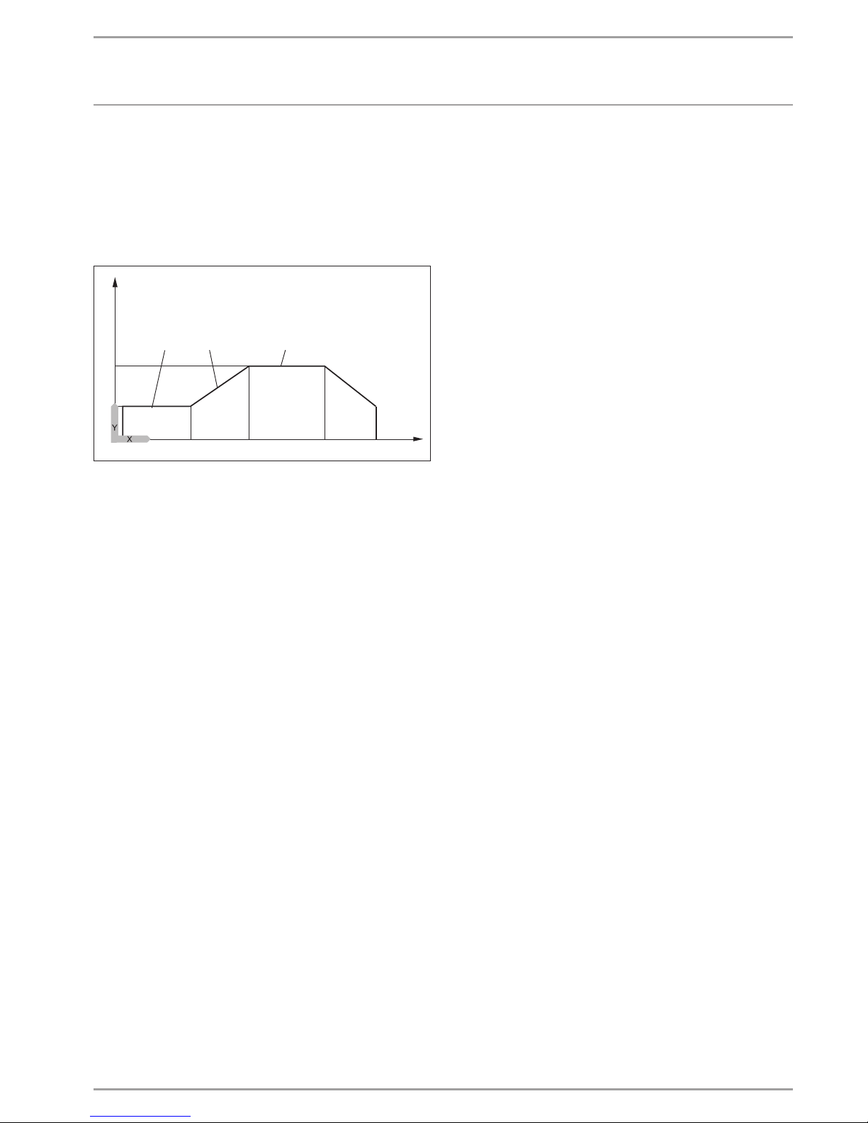
The low end temperature (parameter LOW END TEMPERATURE)
is held for the selected time (parameter DURATION BASE TEMP).
After expiry of this period, the system heats to the maximum low
end temperature (parameter MAXIMUMTEMPERATURE) using
an increase K/day (parameter RISEPERDAY) and holds this maximum temperature for the selected time (parameter MAXTEMPERATURE DURATION). The system subsequently returns to the
low end temperature using the same steps as for heat-up.
1
7
4 5
3
2
84�03�01�0038
6
Y Temperature
X Time
1 Maximum temperature
2 Low end temperature
3 Low end temperature duration
4 Increase K/day
5 Max temperature duration
6 Start
7 End
If a heating buffer cylinder has been integrated into the system,
the temperature in the buffer cylinder is controlled solely via the
return sensor (fitted at the base of the buffer cylinder). If only the
direct heating circuit 1 is operational, the set values are reduced
by 5K to even out temperature differences in the buffer cylinder.
If 2 heating circuits are operational (second heating circuit is for
underfloor heating system), the mixer in heating circuit 2 regulates
down to the selected set values. The pump for heating circuit 1
is not controlled.
During the heat-up program the appliance often reaches maximum output. For this reason, energy consumption and noise levels
are comparatively high during screed drying.
After the heat-up process all modified parameters must be reset
to their standard values or system values.
Emergency operation is not possible while the heat-up program
is active.
5.3.6 SILENT PROGRAM 1
For HP types 1/1* (not for WPL 34/47) and 4/4*, the fan speed is
reduced. This reduces the sound level emitted by the heat pump.
For HP types 3/3* and 5/5*, both the fan speed and the compressor
output can be reduced. Both options can be set independently of
one another.
5.3.7 SILENT PROGRAM 2
In this program, the air source heat pump is switched off for the
entire set period and only the internal or external secondary heat
generator is used for heating.
PLEASE NOTE: This program may result in high electricity bills.

OPERATION
Menu structure
16 | WPM 3 www.stiebel-eltron.com
5.4 SETTINGS menu
Here you can set all system-specific parameters for heating, cooling and DHW modes as well as general settings such as the time.
Note
Some menu items are protected by a code and can only be accessed and adjusted by a qualified contractor.
Note
Not all appliance parameters are displayed in the different menus, depending on which heat pump type is connected.
Level 2 Level 3 Level 4 Level 5
GENERAL
TIME / DATE TIME
YEAR
MONTH
DAY
SET SUMMER TIME DAY BEGINNING
DAY ENDING
CONTRAST
BRIGHTNESS
TOUCH SENSITIVITY
TOUCH ACCELERATION
HEAT ING
HEATING CIRCUIT 1 COMFORT TEMPERATURE
ECO TEMPERATURE
MINIMUM TEMPERATURE
ROOM INFLUENCE
HEATING CURVE RISE
HEATING CURVE VIEW
HEATING CIRCUIT 2 COMFORT TEMPERATURE
ECO TEMPERATURE
MINIMUM TEMPERATURE
MAXIMUM TEMPERATURE
MIXER DYNAMICS
ROOM INFLUENCE
HEATING CURVE RISE
HEATING CURVE VIEW
STANDARD SETTING BUFFER OPERATION
SUMMER MODE OUTSIDE TEMPERATURE
BUILDING HEAT BUFFER
FLOW PROP HEATING CIRC
MAXIMUM RETURN TEMP
MAXIMUM FLOW TEMPERATURE
FIXED VALUE OPERATION
HEATING CIRCUIT OPTIMAL
FROST PROTECTION
REMOTE CONTROL FE7 HEATING CIRC PRESELECTION
ROOM INFLUENCE
ROOM CORRECTION
PUMP CYCLES
EXTERNAL HEAT SOURCE THREADED IMMERSION HEATER
BOILER
HZG PWM
HEATING CURVE GAP

OPERATION
Menu structure
www.stiebel-eltron.com WPM 3| 17
Level 2 Level 3 Level 4 Level 5
SET BOILER TEMPERATURE
BLOCKING TIME EVU
LOWER APP LIMIT HZG
DUAL MODE TEMP HZG
HZG PWM
ELECTRIC REHEATING LOWER APP LIMIT HZG
DUAL MODE TEMP HZG
NUMBER OF STAGES
DEL AY
DHW
DHW TEMPERATURES COMFORT TEMPERATURE
ECO TEMPERATURE
STANDARD SETTING DHW MODE PRIORITY OPERATION
PARALLEL OPERATION
PARTIAL PRIORITY
DHW HYSTERESIS
DHW STAGES
AUTOMATIC DHW CONTROL OUTSIDE TEMPERATURE
WW LEARNING FUNCTION
COMBI CYLINDER
WW OUTPUT WP WW OUTPUT SUMMER
WW OUTPUT WINTER
MAXIMUM FLOW TEMPERATURE
PASTEURISATION
ELECTRIC REHEATING DUAL MODE TEMP WW
LOWER APP LIMIT WW
EXTERNAL HEAT SOURCE SUPPORTED
ALONE
INDEPENDENT
DUAL MODE TEMP WW
LOWER APP LIMIT WW
WW PWM
COOLING
COOLING
COOLING MODE PA SSIVE COOLING
ACTIVE COOLING
STANDARD SETTING COOLING STAGES
COOLING LIMIT
COOLING CAPACITY
ACTIVE COOLING AREA COOLING SET FLOW TEMPERATURE
FLOW TEMP HYSTERESIS
SET ROOM TEMPERATURE
DYNAMICS ACTIVE
DYNAMICS PASSIVE
FAN COOLING SET FLOW TEMPERATURE
FLOW TEMP HYSTERESIS
SET ROOM TEMPERATURE
DYNAMICS ACTIVE
DYNAMICS PASSIVE
PASSIV E COOLING AREA COOLING SET FLOW TEMPERATURE
FLOW TEMP HYSTERESIS
SET ROOM TEMPERATURE
DYNAMICS PASSIVE
FAN COOLING SET FLOW TEMPERATURE
 Loading...