

OPERATION AND INSTALLAT ION
Air | water heat pump
» WPL 34
» WPL 47
» WPL 57

CONTENTS
SPECIAL INFORMATION
OPERATION
1. General information �����������������������������������������4
1.1 Safety instructions ����������������������������������������������� 4
1.2 Other symbols in this documentation ����������������������� 4
1.3 Units of measurement ������������������������������������������ 4
1.4 Standardised output data �������������������������������������� 4
2. Safety ���������������������������������������������������������� 5
2.1 Intended use ������������������������������������������������������ 5
3. Appliance description ���������������������������������������5
3.1 Properties ��������������������������������������������������������� 5
3.2 Function ����������������������������������������������������������� 5
3.3 Equipment features ��������������������������������������������� 5
4. Operation �����������������������������������������������������5
5. Maintenance and care ���������������������������������������6
6. Troubleshooting ����������������������������������������������6
INSTALLATION
7. Safety ���������������������������������������������������������� 7
7.1 General safety instructions ������������������������������������ 7
7.2 Instructions, standards and regulations �������������������� 7
8. Appliance description ���������������������������������������7
8.1 Standard delivery ������������������������������������������������ 7
8.2 Required accessories ������������������������������������������� 7
8.3 Further accessories���������������������������������������������� 7
8.4 System configuration ������������������������������������������� 7
9. Preparations �������������������������������������������������� 7
9.1 Sound emissions ������������������������������������������������� 7
9.2 Minimum clearances �������������������������������������������� 8
9.3 Substrate ���������������������������������������������������������� 8
9.4 Heat pump manager WPM ������������������������������������� 9
9.5 Buffer cylinder ��������������������������������������������������� 9
9.6 Electrical installation�������������������������������������������� 9
10. Installation �������������������������������������������������� 10
10.1 Transport ��������������������������������������������������������� 10
10.2 Siting �������������������������������������������������������������� 10
10.3 Heating water connection ������������������������������������� 10
10.4 Oxygen diffusion ������������������������������������������������ 10
10.5 Filling the heating system ������������������������������������ 10
10.6 Minimum flow rate ��������������������������������������������� 10
10.7 Condensate drain ����������������������������������������������� 11
10.8 Second heat source��������������������������������������������� 11
10.9 Safety temperature controller for underfloor heating
system STB-FB �������������������������������������������������� 11
11. Power supply ����������������������������������������������� 11
11.1 General ����������������������������������������������������������� 11
11.2 Wiring chamber ������������������������������������������������� 11
11.3 Electrical connections ������������������������������������������ 12
12. Fitting casing components �������������������������������� 12
13. Commissioning ��������������������������������������������� 14
13.1 Checks before commissioning�������������������������������� 14
13.2 Initial start-up ��������������������������������������������������� 14
13.3 Shutdown ��������������������������������������������������������15
14. Troubleshooting �������������������������������������������� 15
14.1 Controls on the IWS �������������������������������������������� 15
14.2 Fan noise ��������������������������������������������������������� 16
15. Maintenance ������������������������������������������������ 16
16. Specification ������������������������������������������������ 17
16.1 Dimensions and connections ��������������������������������� 17
16.2 Wiring diagram WPL 34 | WPL 47 ���������������������������� 18
16.3 Wiring diagram WPL 57 ��������������������������������������� 20
16.4 Output diagrams WPL 34 �������������������������������������� 22
16.5 Output diagrams WPL 47 �������������������������������������� 24
16.6 Output diagrams WPL 57 �������������������������������������� 26
16.7 Data table �������������������������������������������������������� 28
GUARANTEE
ENVIRONMENT AND RECYCLING
2 | WPL 34 | WPL 47 | WPL 57 www.stiebel-eltron.com

SPECIAL INFORMATION
SPECIAL INFORMATION
- The appliance may be used by children aged8
and up and persons with reduced physical, sensory or mental capabilities or a lack of experience
and know-how, provided that they are supervised
or they have been instructed on how to use the
appliance safely and have understood the resulting risks. Children must never play with the appliance. Children must never clean the appliance
or perform user maintenance unless they are
supervised.
- The connection to the power supply must be in
the form of a permanent connection. Ensure the
appliance can be separated from the power supply by an isolator that disconnects all poles with
at least 3mm contact separation.
- Maintain the minimum clearances to ensure trouble-free operation of the appliance and facilitate
maintenance work.
- There is no need to shut the system down in
summer. The heat pump manager has an automatic summer / winter changeover.
- In dual mode operation, return water from the
second heat generator may flow through the heat
pump. Please note that the return water temperature may be a maximum of 60 °C.
- Maintenance work, such as checking the electrical safety, must only be carried out by a qualified
contractor.
- We recommend an annual inspection (to establish
the system's current condition), and maintenance
by a qualified contractor if required (to return the
system to the desired condition).
- Keep the air discharge and inlet apertures free
from snow and leaves.
- Check regularly whether water collects beneath
the appliance.
- Once per year, the refrigerant circuit must be tested for leaks in accordance with the EC Directive
517/2014. The tightness test must be documented
in the log.
- Never interrupt the power supply, even outside
the heating season. The system's active frost protection is not guaranteed if the power supply is
interrupted.
www.stiebel-eltron.com WPL 34 | WPL 47 | WPL 57 | 3
OPERATION
General information
OPERATION
1. General information
The chapters "Special Information" and "Operation" are intended
for both the user and qualified contractors.
The chapter "Installation" is intended for qualified contractors.
Note
Read these instructions carefully before using the appliance and retain them for future reference.
Pass on the instructions to a new user if required.
1.1 Safety instructions
1.1.1 Structure of safety instructions
KEYWORD Type of risk
!
Here, possible consequences are listed that may result
from failure to observe the safety instructions.
Steps to prevent the risk are listed.
1.1.2 Symbols, type of risk
Symbol Type of risk
!
1.1.3 Keywords
KEYWORD Meaning
DANGER Failure to observe this information will result in serious
WARNING Failure to observe this information may result in serious
CAUTION Failure to observe this information may result in non-seri-
Injury
Electrocution
Burns
(burns, scalding)
injury or death.
injury or death.
ous or minor injury.
1.2 Other symbols in this documentation
Note
General information is identified by the adjacent symbol.
Read these texts carefully.
Symbol Meaning
!
This symbol indicates that you have to do something. The ac-
tion you need to take is described step by step.
Material losses
(appliance damage, consequential losses and environmental pollution)
Appliance disposal
1.3 Units of measurement
Note
All measurements are given in mm unless stated otherwise.
1.4 Standardised output data
Explanations to determine and interpret the specified standardised
output data
1.4.1 Standard: EN 14511
The output data specifically mentioned in text, diagrams and
technical datasheets has been determined in line with the test
conditions described in the standard shown in the heading of
this chapter.
Generally, these standardised test conditions will not fully meet
the conditions found at the installation site of the system user.
Depending on the chosen test method and the extent to which
the selected method deviates from the conditions described in the
standard shown in the heading of this chapter, any deviations can
have a considerable impact. Further factors that have an influence
on the test values are the measuring equipment, the system configuration, the age of the system and the flow rates.
A confirmation of the specified output data can only be obtained
if the conditions applicable to the relevant test match those of the
standard shown in the heading of this chapter.
4 | WPL 34 | WPL 47 | WPL 57 www.stiebel-eltron.com
OPERATION
Safety
2. Safety
2.1 Intended use
This appliance is intended for central heating and DHW heating in
domestic applications. It can be used safely by untrained persons.
The appliance can also be used in a non-domestic environment,
e.g. in a small business, as long as it is used in the same way.
Any other use beyond that described shall be deemed inappropriate. Observation of these instructions and of instructions for any
accessories used is also part of the correct use of this appliance.
Observe the application limits (see chapter "Specification / Data
table").
Operate the appliance only when fully installed and with all safety
equipment fitted.
Protect the appliance from dust and dirt ingress during building
work.
WARNING Injury
!
The appliance may be used by children aged 8 and older
and persons with reduced physical, sensory or mental
capabilities or a lack of experience and know-how, provided that they are supervised or they have been instructed on how to use the appliance safely and have
understood the resulting risks. Children must never play
with the appliance. Children must never clean the appliance or perform user maintenance unless they are
supervised.
WARNING Injury
!
For safety reasons, only operate the appliance with
the casing closed.
3. Appliance description
3.1 Properties
The appliance is an air|water heat pump that operates as a heating heat pump. Heat is extracted from the outdoor air at a low
temperature level, and is then transferred to the heating water at
a higher temperature. The heating water can be heated up to a
flow temperature of 60 °C.
Operational characteristics:
- Suitable for underfloor and radiator heating.
- Heat pump operates most efficiently on a low-temperature
heating system.
- Still extracts heat from the outdoor air at - 20 °C outside
temperature.
Note
The WPL 57 features a silent mode. Silent mode enables
the heat pump noise emissions to be reduced.
- Silent program 1 reduces the fan speed.
- Silent program 2 switches the heat pump off.
Heating will [then] be provided by the internal or
external second heat source. This results in higher
electricity bills.
Where required, set silent mode in the heat pump
manager.
3.2 Function
Heat is extracted from the outdoor air via the heat exchanger
(evaporator) on the air side. The now evaporated refrigerant is
compressed with a compressor. This process requires electrical
energy. This electrical energy helps to heat the room.
At air temperatures below approx. + 7 °C, the humidity in the air
condenses as hoarfrost on the evaporator fins. Any hoarfrost is automatically defrosted. Water created from this defrosting process
collects in the defrost pan and is drained off via a hose.
The heat pump automatically reverts to heating mode at the end
of the defrost cycle.
Material losses
!
In dual mode operation, return water from the second
heat generator may flow through the heat pump. Please
note that the return water temperature may be a maximum of 60 °C.
3.3 Equipment features
- Corrosion-protected, external casing made from galvanised
sheet steel plus powder-coated finish.
- Comprises all components and safety equipment required for
operation.
- Filled with non-combustible safety refrigerant.
4. Operation
Operation is exclusively controlled via the heat pump manager.
Observe the heat pump manager operating and installation
instructions.
Note
For centralised control of the heating system, you would
need the WPM heat pump manager.
www.stiebel-eltron.com WPL 34 | WPL 47 | WPL 57 | 5
OPERATION
Maintenance and care
5. Maintenance and care
Material losses
!
Maintenance work, such as checking the electrical safety,
must only be carried out by a heating contractor.
We recommend an annual inspection (to establish the system's
current condition), and maintenance by a qualified contractor if
required (to return the system to the desired condition).
A damp cloth is sufficient for cleaning all plastic and sheet
metal parts. Never use abrasive or corrosive cleaning agents.
Note
Keep the air discharge and intake apertures free from
snow and leaves.
Check regularly whether water collects beneath the
appliance.
In the event of water collecting beneath the appliance, call
a qualified contractor to have the condensate drain cleaned
out.
Note
Once per year, the refrigerant circuit must be tested for
leaks in accordance with the EC Directive 517/2014.
The tightness test must be documented in the log.
6. Troubleshooting
Fault Cause Remedy
There is no hot
water or the heating system stays
cold.
Water is leaking
from the appliance.
Condensate is
collecting on the
outside of the appliance.
Note
Even when the condensate is draining away correctly,
expect water to drip from the appliance onto the floor.
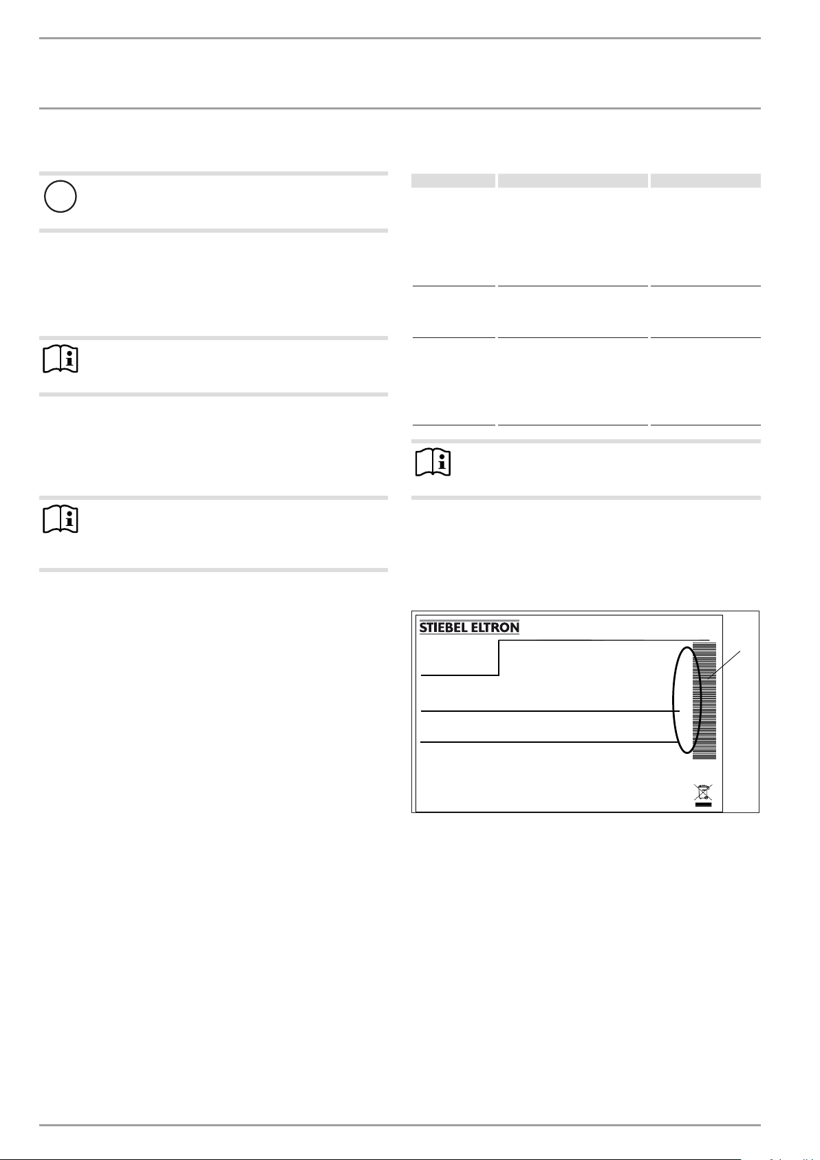
If you cannot remedy the fault, notify your qualified contractor. To
facilitate and speed up your request, provide the number from the
type plate (000000-0000-000000). The type plate is located at the
front top, on the right or left hand side of the casing.
No power at the appliance.
The condensate drain may be
blocked.
The heat pump is drawing heat
from the outdoor air to heat
the building. This can cause the
humidity in the outdoor air to
accumulate as dew or frost on the
cooled heat pump casing. This is
not a defect.
Check the fuses/MCBs in
your fuse box/distribution panel. Replace the
fuses/reset the MCBs if
required. Notify your
qualified contractor if
the fuses/MCBs blow/
trip again.
Clean the condensate
drain as described in
chapter 'Care and maintenance'.
Example
Montageanweisung beachten! Dichtheit geprüft!
1 Number on the type plate
Made in Germany
*xxxxxxxxxxxxxxxxxx*
1
26�03�01�1430
6 | WPL 34 | WPL 47 | WPL 57 www.stiebel-eltron.com
INSTALLATION
Safety
INSTALLATION
7. Safety
Only a qualified contractor should carry out installation, commissioning, maintenance and repair of the appliance.
7.1 General safety instructions
We guarantee trouble-free function and operational reliability only
if original accessories and spare parts intended for the appliance
are used.
7.2 Instructions, standards and regulations
Note
Observe all applicable national and regional regulations
and instructions.
8. Appliance description
For outdoor installation the appliance offers additional frost protection of the heating water pipes. The integral frost protection
circuit starts the circulation pump in the heat pump circuit automatically at +8 °C condenser temperature, and thereby ensures
circulation in all water-filled sections. The heat pump is started
automatically no later than when the temperature inside the buffer
cylinder drops below +5 °C.
8.2 Required accessories
You require the following accessories to operate the heat pump:
- Heat pump manager WPM 3
- Remote control for heating systems FE7
- Buffer cylinder
- Circulation pump UP30/1-8PCV
8.3 Further accessories
- Internet Service Gateway ISG
- Mixer module MSMW
- Contact sensor
- Immersion sensor
8.4 System configuration
You will find the accessory drawings and versions in the specific
technical guides for your system.
9. Preparations
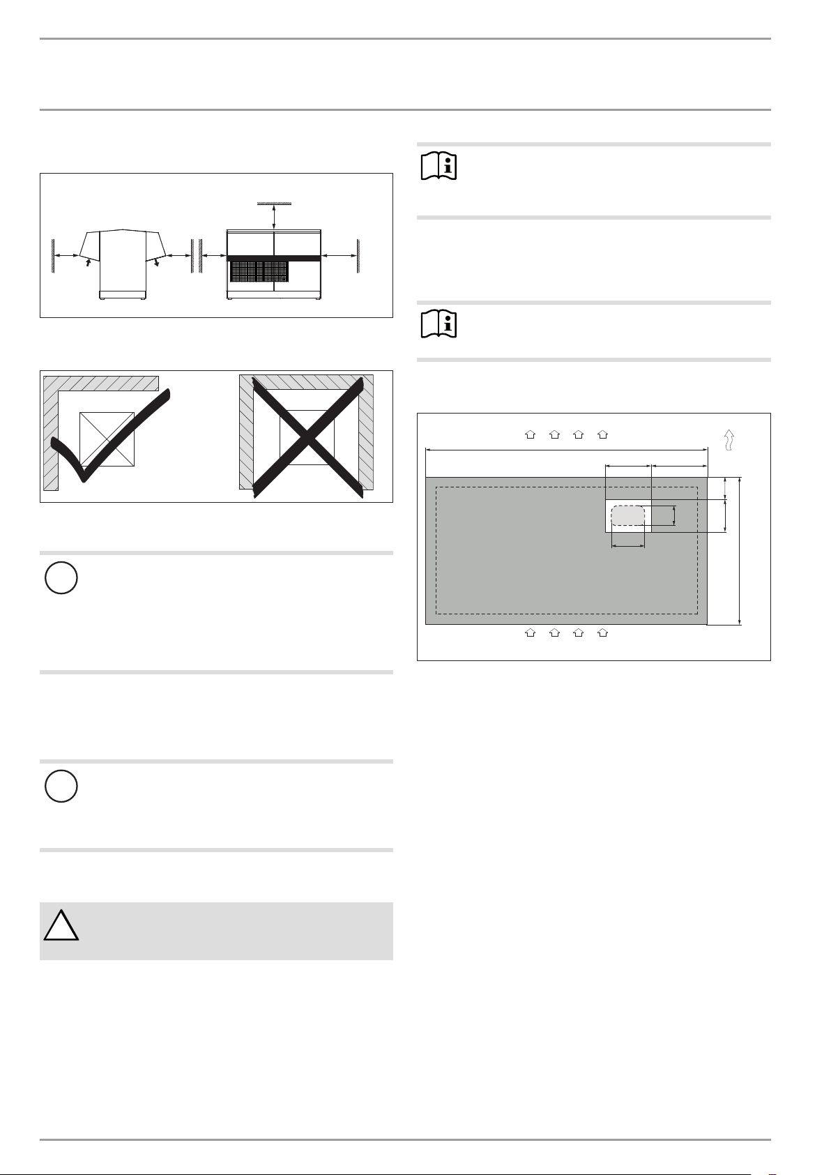
9.1 Sound emissions
The appliance is louder on the air intake and air discharge sides
than on the two enclosed sides. Observe the following information
when selecting the installation location.
Note
For details regarding the sound power level, see chapter
"Specification / Data table".
8.1 Standard delivery
The casing components for the appliance are delivered in a separate pack.
8.1.1 Standard appliance
- Logbook
- Type plate
- Condensate drain hose
- Wiring diagram
8.1.2 Casing components
- 2 Covers
- 4 Air deflector hoods
- 1 Front panel
- 1 Back panel
- 4 Side panels
- 4 Plinth trim
- Lawn areas and shrubs help reduce the spread of noise.
- Sound propagation can also be reduced by installing closely
spaced palisade fencing around the appliance.
Ensure that the air intake direction is the same as the dom-
inant wind direction. Air should not be drawn in against the
wind.
Never direct the air intake or discharge towards noise-sensi-
tive rooms of the house, e.g. bedrooms.
Avoid installation on large, echoing floor areas, e.g. tiled
floors.
Avoid installation between reflective building walls. Reflect-
ing building walls can increase the noise level.
www.stiebel-eltron.com WPL 34 | WPL 47 | WPL 57 | 7
INSTALLATION
Preparations
9.2 Minimum clearances
≥500
≥500
≥500
Maintain the minimum clearances to ensure trouble-free op-
eration of the appliance and facilitate maintenance work.
Never install the appliance in a recess. Two sides of the ap-
pliance must remain exposed.
Material losses
!
Please note that both the flow of outdoor air into the
appliance, and the flow of exhaust air from the appliance
must be unimpeded.
If the air intake and discharge of the appliance are obstructed by surrounding objects, this may cause a thermal
short-circuit.
Ensure that the appliance is not fully enclosed by objects
such as buildings, walls or fences.
If necessary, maintain a greater clearance to the surrounding
objects.
≥500
≥1000
Note
If the air discharge side faces house walls, maintain a
minimum clearance of 2m between the appliance and
the building.
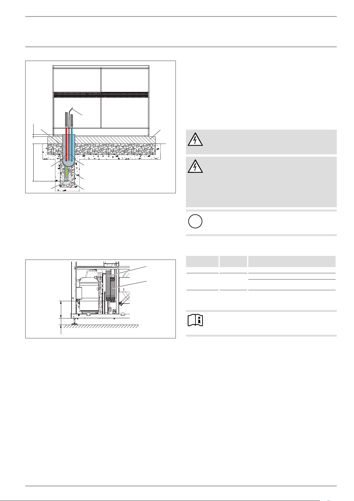
9.3 Substrate
The substrate must be horizontal, level, solid and permanent.
Observe chapter "Sound emissions".
D0000020332
Example: Foundations with recess
91�00�00�0036
1 Air discharge
2 Air intake
3 Main wind direction
4 Supply line outlet
5 Knock-out inside the appliance
Note
Provide a recess (space) in the substrate to enable water
and electrical pipes/cables to be connected from below.
1
2200
360
4
5
260
2
440
155
3
173255
1150
D0000026155
Material losses
!
The air flow rate through the appliance must not fall
below the minimum level. If the air flow rate falls below
the minimum level, trouble-free operation of the appliance is not guaranteed.
Ensure that the minimum air flow rate is maintained. Ob-
serve the details in chapter "Specification / Data table".
WARNING Injury
!
On the air discharge side, discharged air can result in the
formation of ice on footpaths and driveways in winter.
If necessary, maintain a greater clearance to the surrounding
objects.
If the air discharge side of the appliance faces a wall of a house,
the cool air from the air discharge may cause condensate to form
on this wall.
8 | WPL 34 | WPL 47 | WPL 57 www.stiebel-eltron.com
INSTALLATION
Preparations
9.5 Buffer cylinder
The installation of a buffer cylinder is essential to ensure trouble-free operation of the appliance.
The buffer cylinder provides hydraulic separation of the volume
flows in the heat pump circuit and heating circuit, and also serves
as an energy source for defrosting.
8
3
≥10
A
1
5
A Depth of frost line
1 Heating flow
2 Heating return
3 Conduit for supply lines/cables
4 Foundation
5 Coarse gravel back filling
6 Condensate drain pipe
7 Condensate drain
8 Electrical power cable
250105
1 Heating flow
2 Heating return
Protect the flow and return pipes and the electrical cables
against damage and moisture with an installation conduit.
Protect the flow and return lines against frost with sufficient
thermal insulation. The required insulation thickness is described in the Energy Savings Ordinance.
Only use weather-resistant cables.
2
7
6
1
2
9.6 Electrical installation
4
WARNING Electrocution
Carry out all electrical connection and installation work
in accordance with national and regional regulations.
WARNING Electrocution
Only use a permanent connection to the power supply.
The appliance must be able to be separated from the
D0000022105
In accordance with VDE 0298-4, use the following line cross-sections subject to their fuse protection:
MCB/fuse
rating
B 16 A Control 1.5 mm²
C 32 A
The electrical specifications are given in the "Data table". You
require aJ-Y(St)2x2x0.8mm² cable for the BUS.
D0000048227
power supply by an isolator that disconnects all poles
with at least 3mm contact separation. This requirement
can be met with contactors, circuit breakers, fuses/
MCBs, etc.
Material losses
!
The specified voltage must match the mains voltage. Observe the type plate.
Assignment Cable cross-section
Compressor 10.0 mm² when routing in a wall.
Note
Provide separate fuses for the two power circuits of the
appliance and the control unit.
6.0 mm² when routing a multi-core line on a
wall or in an electrical conduit on a wall.
9.4 Heat pump manager WPM
A WPM heat pump manager is required to operate the appliance.
This controls the heat pump and regulates the heating system.
www.stiebel-eltron.com WPL 34 | WPL 47 | WPL 57 | 9
INSTALLATION
Installation
10. Installation
10.1 Transport
Pay attention to the appliance's centre of gravity when trans-
porting the appliance.
The centre of gravity is in the area where the compressor is located.
Protect the appliance against heavy impact during transport.
Where space is restricted, you can also tilt the appliance at an
angle to move it.
10.2 Siting
Pay attention to the air discharge direction.
Position the appliance on the prepared substrate.
Level the appliance horizontally by adjusting the feet.
Route the water pipes and electrical cables into the appliance
from below through the knock-outs in the base.
Note
Do not fit the casing components until the electrical and
hydraulic connections have been made.
10.3 Heating water connection
The heating system to which the heat pump is connected must be
installed by a qualified contractor in accordance with the water
installation drawings that are part of the technical guides.
Thoroughly flush the pipework before connecting the heat
pump.
Debris, such as welding pearls, rust, sand, sealant, etc. can impair
the operational reliability of the heat pump.
10.4 Oxygen diffusion
Material losses
!
Avoid open heating systems and plastic pipes in underfloor heating systems which are permeable to oxygen.
In underfloor heating systems with plastic pipes that are permeable to oxygen and in open vented heating systems, oxygen
diffusion may lead to corrosion on the steel components of the
heating system (e.g. on the indirect coil of the DHW cylinder, on
buffer cylinders, steel heating elements or steel pipes).
Material losses
!
The products of corrosion (e.g. rusty sludge) can settle in
the heating system components and can result in a lower
output or fault shutdowns due to reduced cross-sections.
10.5 Filling the heating system
10.5.1 Heating water quality
Carry out a fill water analysis before the system is filled. This may,
for example, be requested by the relevant water supply utility.
Material losses
!
To avoid damage as a result of scaling, it may be necessary to soften or desalinate the fill water. Always observe
the fill water limits specified in the "Specification / Data
table" chapter.
Recheck these limits 8-12 weeks after commission-
ing and as part of the annual system maintenance.
Note
With a conductivity >1000 μS/cm, desalination treatment
is recommended in order to avoid corrosion.
Note
Suitable appliances for water softening and desalinating,
as well as for charging and flushing heating systems, can
be obtained via trade suppliers.
Note
If you treat the fill water with inhibitors or additives, the
same limits as for desalination apply.
10.5.2 Venting the heating system
Vent the pipework carefully. For this, also activate the air
vent valve integrated into the heating flow inside the heat
pump.
10.6 Minimum flow rate
The minimum flow rate is set via the temperature differential of
the buffer circuit.
Set the buffer charging pump so that the value is equal to or lower
than the maximum temperature differential.
The setting is made in heat pump mode. For this, make the following settings first:
Temporarily remove the fuse from the electric emergency/
booster heater to isolate the emergency/booster heater from
the power supply. Alternatively, switch OFF the second heat
generator.
Operate the appliance in heating mode.
10.6.1 Flow rate with buffer cylinder
When using a buffer cylinder, make the following setting: In the
menu "SETTINGS/ HEATING/ STANDARD SETTINGS", set parameter "BUFFER OPERATION" to "ON".
The flow rate can be adjusted using the temperature differential
of the buffer circuit. The value must not fall below the minimum
flow rate.
10 | WPL 34 | WPL 47 | WPL 57 www.stiebel-eltron.com
 Loading...