

STIEBEL ELTRON WPL 08 S Trend, WPL 28 Trend, WPL 12 S Trend, WPL 22 Trend, WPL 16 S Trend Operation And Installation
OPERATION AND INSTALLAT ION
Air source heat pump
» WPL 08 S Trend
» WPL 12 S Trend
» WPL 16 S Trend
» WPL 22 Trend
» WPL 28 Trend

CONTENTS
SPECIAL INFORMATION
OPERATION
1. General information �����������������������������������������3
1.1 Relevant documents_____________________________________________ 3
1.2 Safety instructions _______________________________________________ 3
1.3 Other symbols in this documentation _______________________ 4
1.4 Units of measurement __________________________________________ 4
1.5 Standardised output data ______________________________________ 4
2. Safety ���������������������������������������������������������� 4
2.1 Intended use ______________________________________________________ 4
2.2 General safety instructions ____________________________________ 4
3. Appliance description ���������������������������������������5
3.1 Function ___________________________________________________________ 5
4. Cleaning, maintenance and care ���������������������������6
5. Troubleshooting ����������������������������������������������6
INSTALLATION
6. Safety ���������������������������������������������������������� 7
6.1 General safety instructions ____________________________________ 7
6.2 Instructions, standards and regulations ____________________ 7
7. Appliance description ���������������������������������������7
7.1 Standard delivery ________________________________________________ 7
7.2 Accessories ________________________________________________________ 7
8. Preparations �������������������������������������������������� 8
8.1 Sound emissions _________________________________________________ 8
8.2 Minimum clearances ____________________________________________ 8
8.3 Preparation of the installation site ___________________________ 9
8.4 Installing supply lines__________________________________________ 10
8.5 Heat pump manager ___________________________________________ 10
8.6 Buffer cylinder __________________________________________________ 10
8.7 Preparing the electrical installation ________________________ 10
9. Installation �������������������������������������������������� 11
9.1 Transport and storage _________________________________________ 11
9.2 Installation notes _______________________________________________ 11
9.3 Heating water connection _____________________________________ 11
9.4 Oxygen diffusion ________________________________________________ 12
9.5 Filling the heating system ____________________________________ 12
9.6 Minimum flow rate _____________________________________________ 12
9.7 Setting the flow rate on the heating side __________________ 12
9.8 Condensate drain _______________________________________________ 14
9.9 Power supply ____________________________________________________ 14
9.10 Fitting the side panels and appliance cover _______________ 16
9.11 Ribbon heater ___________________________________________________ 18
10. Commissioning ��������������������������������������������� 19
10.1 Checks before commissioning________________________________ 19
10.2 Settings ___________________________________________________________ 19
10.3 Appliance handover ____________________________________________ 20
10.4 Recommissioning _______________________________________________ 20
10.5 Operation and control _________________________________________ 20
10.6 Shutdown ________________________________________________________ 20
11. Maintenance ������������������������������������������������ 20
11.1 Cleaning the evaporator _______________________________________ 21
11.2 Fan noise _________________________________________________________ 21
12. Specification ������������������������������������������������ 22
12.1 Dimensions and connections _________________________________ 22
12.2 Wiring diagrams ________________________________________________ 24
12.3 Operating range w/o electric emergency/booster
heater _____________________________________________________________ 26
12.4 Performance diagram WPL 08 S Trend _____________________ 26
12.5 Performance diagram WPL 12 S Trend _____________________27
12.6 Performance diagram WPL 16 S Trend _____________________27
12.7 Performance diagram WPL 22 Trend________________________28
12.8 Performance diagram WPL 28 Trend________________________28
12.9 Data table ________________________________________________________ 29
GUARANTEE
ENVIRONMENT AND RECYCLING
2 | WPL 08-28 (S) Trend www.stiebel-eltron.com

SPECIAL INFORMATION | OPERATION
General information
SPECIAL INFORMATION
- The appliance may be used by children aged8
and older and persons with reduced physical,
sensory or mental capabilities or a lack of experience and know-how, provided that they are
supervised or they have been instructed on how
to use the appliance safely and have understood
the resulting risks. Children must never play with
the appliance. Children must never clean the appliance or perform user maintenance unless they
are supervised.
- The connection to the power supply must be in
the form of a permanent connection. Ensure the
appliance can be separated from the power supply by an isolator that disconnects all poles with
at least 3mm contact separation.
- Maintain the minimum clearances to ensure trouble-free operation of the appliance and facilitate
maintenance work.
OPERATION
1. General information
The chapters „Special Information“ and „Operation“ are intended
for both the user and qualified contractors.
The chapter „Installation“ is intended for qualified contractors.
Note
Read these instructions carefully before using the appliance and retain them for future reference.
Pass on the instructions to a new user if required.
1.1 Relevant documents
Operating and installation instructions for heat pump
manager
Operating and installation instructions for attached in-
ternal unit
1.2 Safety instructions
1.2.1 Structure of safety instructions
- Maintenance work, such as checking the electrical safety, must only be carried out by a qualified
contractor.
- We recommend an annual inspection (to establish
the current condition of the system), and maintenance by a qualified contractor if required (to
return the system to its original condition).
- Following isolation from the mains supply, parts
of the appliance may remain live for up to 5minutes. This is because the capacitors on the inverter still have to discharge.
- Never interrupt the power supply, even outside
the heating period. The system‘s active frost protection is not guaranteed if the power supply is
interrupted.
- If the heat pump and frost protection are completely switched off, drain the system on the
water side.
KEYWORD Type of risk
!
Here, possible consequences are listed that may result
from failure to observe the safety instructions.
Steps to prevent the risk are listed.
1.2.2 Symbols, type of risk
Symbol Type of risk
!
1.2.3 Keywords
KEYWORD Meaning
DANGER Failure to observe this information will result in serious
WARNING Failure to observe this information may result in serious
CAUTION Failure to observe this information may result in non-seri-
Injury
Electrocution
injury or death.
injury or death.
ous or minor injury.
www.stiebel-eltron.com WPL 08-28 (S) Trend | 3
OPERATION
Safety
1.3 Other symbols in this documentation
Note
General information is identified by the adjacent symbol.
Read these texts carefully.
Symbol Meaning
!
This symbol indicates that you have to do something. The ac-
tion you need to take is described step by step.
Material losses
(appliance damage, consequential losses and environmental pollution)
Appliance disposal
1.4 Units of measurement
Note
All measurements are given in mm unless stated otherwise.
1.5 Standardised output data
Explanations to determine and interpret the specified standardised
output data.
1.5.1 EN 14511
The output data specifically mentioned in text, diagrams and
technical datasheets has been calculated according to the test
conditions of the standard shown in the heading of this section.
However, there is a deviation from this norm in the output data for
air/water inverter heat pumps at source temperatures of > -7°C
as this concerns partial load values. The associated percentage
weighting in the partial load range can be found in EN14825 and
EHPA quality label regulations.
Generally, the test conditions stated above will not fully meet the
conditions found at the installation site of the system user.
Depending on the chosen test method and the extent to which
this method deviates from the test conditions defined in the first
paragraph of this section, any deviations can have a considerable
impact.
Further factors that have an influence on the test values are the
measuring equipment, the system configuration, the age of the
system and the flow rates.
A confirmation of the specified output data can only be obtained
if the test conducted for this purpose is also performed in accordance with the test conditions defined in the first paragraph
of this section.
2. Safety
2.1 Intended use
This appliance may only be installed in sealed hot water heating
systems in accordance with EN12828.
This appliance is intended for domestic use. It can be used safely
by untrained persons. The appliance can also be used in a non-domestic environment, e.g. in a small business, as long as it is used
in the same way.
Any other use beyond that described shall be deemed inappropriate. Observation of these instructions and of instructions for any
accessories used is also part of the correct use of this appliance.
2.2 General safety instructions
WARNING Injury
!
The appliance may be used by children aged 8 and older
and persons with reduced physical, sensory or mental
capabilities or a lack of experience and know-how, provided that they are supervised or they have been instructed on how to use the appliance safely and have
understood the resulting risks. Children must never play
with the appliance. Children must never clean the appliance or perform user maintenance unless they are
supervised.
WARNING Injury
!
For safety reasons, only operate the appliance with
the casing closed.
Observe the following safety instructions and regulations.
- Only qualified contractors may carry out the electrical work
and installation of this appliance.
- The qualified contractor is responsible for adherence to all
currently applicable instructions during installation and
commissioning.
- Operate the appliance only when fully installed and with all
safety equipment fitted.
- Protect the appliance from dust and dirt ingress during
building work.
4 | WPL 08-28 (S) Trend www.stiebel-eltron.com
OPERATION
Appliance description
3. Appliance description
This appliance is a heat pump designed for outdoor installation.
This appliance is used to connect an internal unit (see the chapter
„Accessories/ Required accessories“).
This appliance functions as an air source heat pump. Heat is extracted from the outdoor air at a low temperature level, and is
then transferred to the heating water at a higher temperature.
Depending on the outside temperature, the heating water can
be heated to a flow temperature of up to 62°C (see the chapter
„Specification/ Operating range w/o electric emergency/booster
heater“).
3.1 Function
3.1.1 Heating
Heat is extracted from the outdoor air via the heat exchanger
(evaporator) on the air side. The evaporated refrigerant is compressed in a compressor. This process requires electrical energy.
This process brings the refrigerant to a higher temperature level.
A further heat exchanger (condenser) transfers the heat to the
heating circuit. During this process, the refrigerant expands, and
the cycle starts from the beginning.
This appliance‘s operating principle is based on demand-dependent control of the compressor output with the addition of an electric emergency/booster heater fitted inside the internal unit. The
heat pump manager controls the heat pump subject to the preset
heating curve.
3.1.2 Automatic defrosting
Defrosting takes different forms depending on the prevailing ambient conditions:
During operation
At outdoor temperatures above +5°C, the heat pump fan operates at maximum speed, while the compressor speed is restricted
until the end of the defrosting process. Heating continues during
defrosting.
By circulation reversal
Material losses
!
In the defrost cycle, the fan is switched off and the heat
pump circuit is reversed. The heat required for defrosting
is drawn from the buffer cylinder. For operation without a
buffer cylinder, observe chapter "Operation / Menu structure / Menu SETTINGS/ STANDARD SETTING/ BUFFER
OPERATION" in the operating and installation instructions
of the WPM. This prevents damage to the heat pump as
a result of unfavourable conditions.
At outdoor temperatures below +5°C, the flow direction in the refrigerant circuit is reversed via a 4/2-way diverter valve. Defrosting
is achieved by routing the compressed gas from the compressor
into the evaporator. During this process, the heating system cools
down slightly. The duration of the defrosting process depends on
the thickness of the ice, the system temperature and the prevailing
outside temperature.
Note
For centralised control of the heating system you will
need the WPM heat pump manager.
If the heat pump cannot cover the heating and hot water demand
of the home, the internal unit automatically starts the electric
emergency/booster heater. This operates together with the heat
pump to generate the required flow temperature.
Operation when the heat pump is disabled
The heat pump automatically shuts down at outdoor temperatures
below –20°C. In this case, the indoor unit‘s electric emergency/
booster heater automatically takes over central heating and DHW
heating. The heat pump automatically shuts down at outside temperatures above +35°C.
When the outside temperature rises above -17°C or falls below
+32°C, the heat pump starts up again.
3.1.3 Cooling
Material losses
!
The heat pump is not suitable for continuous, year-round
cooling.
Observe the application limits (see chapter "Specifi-
cation/ Data table").
Rooms are cooled by reversing the heat pump circuit. Heat is
extracted from the heating water and the evaporator transfers
this heat to the outdoor air.
Area cooling requires the installation of the FEK remote control
unit in a reference room to capture the relative humidity and the
room temperature as part of monitoring the dew point.
Heat pump application limit
The heat pump is switched off if the outside temperature falls
below the selected lower application limit for cooling (parameter
LIMITCOOLING).
In cooling mode the heat pump shuts down if the outside temperature rises above +45°C. When the outside temperature falls
below +42°C, the heat pump starts up again.
www.stiebel-eltron.com WPL 08-28 (S) Trend | 5
OPERATION
Cleaning, maintenance and care
4. Cleaning, maintenance and care
Material losses
!
Only qualified contractors may perform maintenance
work, such as electrical safety checks.
- A damp cloth is sufficient for cleaning all plastic and sheet
metal parts. Never use abrasive or corrosive cleaning agents.
- Check the condensate drain monthly (visual inspection).
Remove any contamination and blockages (see the chapter
„Installation/ Condensate drain“).
- Keep the air discharge and intake apertures free from snow
and leaves.
- We recommend an annual inspection (to establish the current condition of the system), and maintenance by a qualified
contractor if required (to return the system to its original
condition).
- Protect the appliance from dust and dirt ingress during
building work.
5. Troubleshooting
Fault Cause Remedy
There is no hot
water or the
heating system
stays cold.
Water is leaking
from the appliance.
Condensate
collects on the
outside of the
appliance and on
the air grille.
If you cannot remedy the fault, notify your contractor. To facilitate
and speed up your request, provide the number from the type
plate (000000-0000-000000).
No power at the appliance.
The condensate drain may be
blocked.
The heat pump is drawing heat
from the outdoor air to heat
the building. This can cause
the humidity in the outdoor air
to accumulate as dew or frost
on the cooled heat pump casing. This is not a defect.
Check the fuses/MCBs in
your fuse box/distribution
panel. Replace the fuses/
reset the MCBs if required.
Notify your qualified contractor if the fuses/MCBs
blow/trip again.
Clean the condensate drain
as described in "Maintenance and care"
Note
Even when the condensate is draining away correctly,
expect water to drip from the appliance onto the floor.
6 | WPL 08-28 (S) Trend www.stiebel-eltron.com
INSTALLATION
Safety
INSTALLATION
6. Safety
Only a qualified contractor should carry out installation, commissioning, maintenance and repair of the appliance.
6.1 General safety instructions
We guarantee the trouble-free function and operational reliability only if original accessories and spare parts intended for the
appliance are used.
6.2 Instructions, standards and regulations
Note
Observe all applicable national and regional regulations
and instructions.
7. Appliance description
7.1 Standard delivery
The following are delivered with the appliance:
- 4 adjustable feet
- 1 appliance cover
- 2 side panels
- 1 front panel
- 8 screws
- 4 washers
- 1 adaptor for return sensor
7.2 Accessories
7.2.1 Required accessories
- Internal unit (hydraulics module, cylinder and hydraulics
module or integral cylinder)
- Pressure hoses
7.2.2 Further accessories
- FEK remote control
- FE7 remote control
- Ribbon heater HZB-1
- Ribbon heater HZB-2
- Water softener HZEA
- Evaporator contact protection BSV 08-16
- Evaporator contact protection BVS 22-28
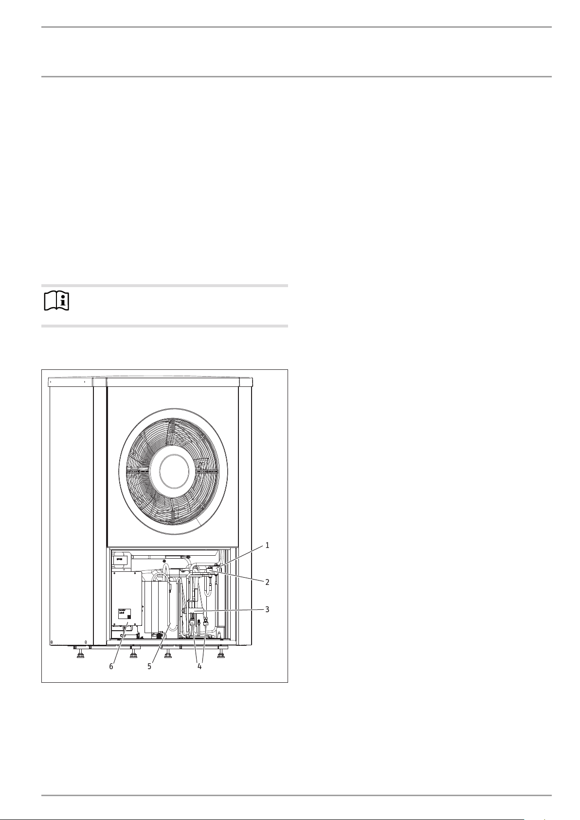
1
2
3
6
1 Electronic expansion valve VR0
2 Electronic expansion valve VR1
3 4-way valve
4 Pressure switch/ pressure sensor
5 Compressor
6 Inverter
www.stiebel-eltron.com WPL 08-28 (S) Trend | 7
5
4
D0000052380
INSTALLATION
Preparations
8. Preparations
!
The appliance is designed for siting in front of a wall. Observe the
minimum clearances. If the appliance is installed in an open space
or on a roof, protect the air intake side. Do this by erecting a wall
to shield it against the wind.
8.1 Sound emissions
Note
For details regarding the sound power level, see the
chapter "Specification/ Data table".
Observe the following information when selecting the installation
site.
- Ensure that the air is drawn in with the wind and expelled
parallel to the main wind direction (see chapter “Preparation
of the installation site / foundations”).
- The appliance generates operating noise.
- The operating noise is louder on the air intake and air discharge sides than on the two enclosed sides.
- Never install the appliance in noise-sensitive rooms. Never
direct the air intake or discharge towards noise-sensitive
rooms of the house, such as bedrooms.
- Installation in corners of buildings or areas surrounded by
walls can result in an elevated noise level. Never install the
appliance in recesses that are surrounded by three walls.
- Reflecting building walls can increase the noise level. Never
install the appliance between reflecting building walls.
- Never install the appliance on large, echoing floor areas,
such as tiled floors.
- Thick palisading and/or lawns and plantings can reduce the
sound propagation.
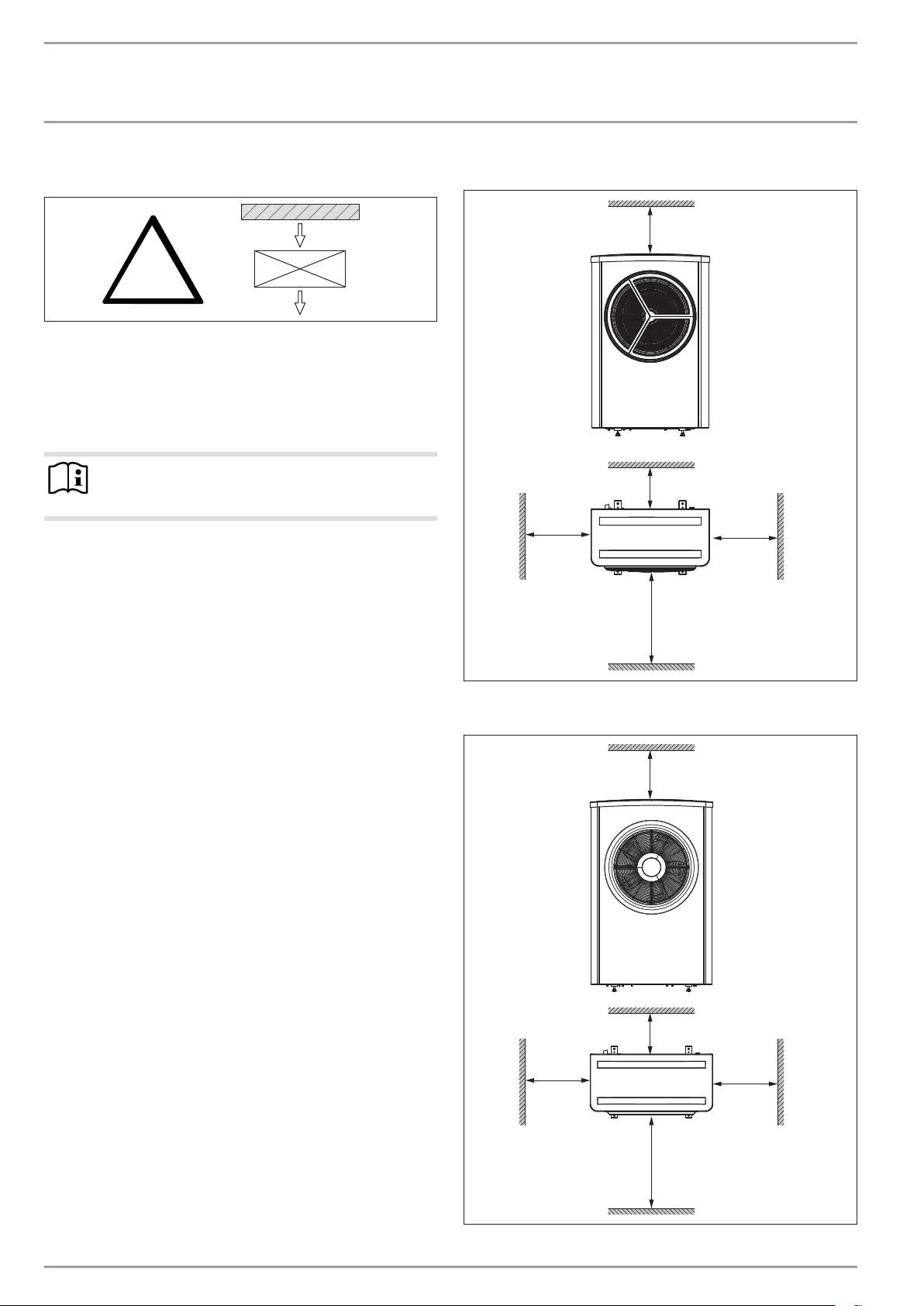
- Maintain the minimum clearances.
WPL 08S Trend | WPL 12S Trend | WPL 16S Trend
≥500
D0000060163
≥400
≥1000
≥2000
WPL 22 Trend | WPL 28 Trend
≥600
≥1000
D0000052367
8.2 Minimum clearances
Maintain the minimum clearances to ensure trouble-free op-
eration of the appliance and facilitate maintenance work.
≥400
≥1000
≥2000
8 | WPL 08-28 (S) Trend www.stiebel-eltron.com
≥1000
D0000052368
INSTALLATION
B
6
Preparations
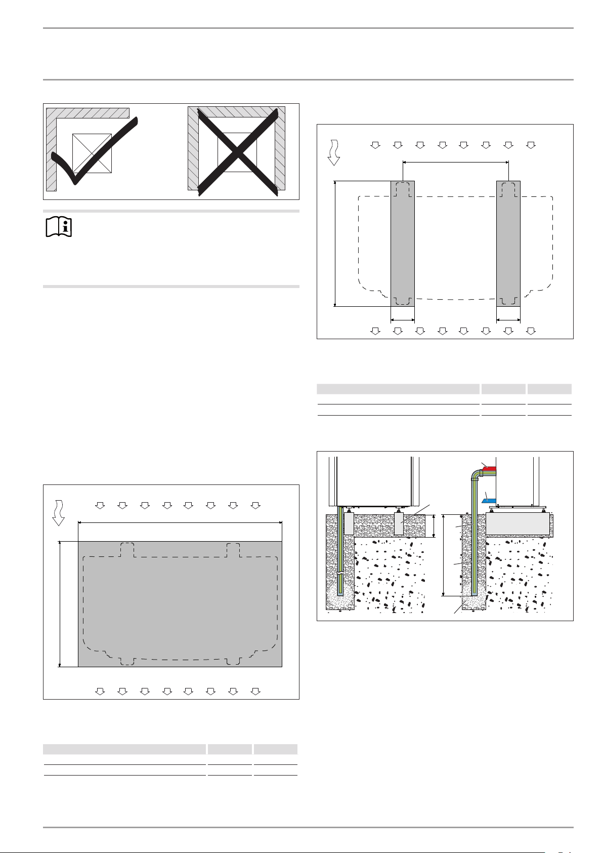
Note
Installation in corners of buildings or areas surrounded by walls can lead to elevated noise levels and severe
evaporator contamination.
Never install the appliance in a recess. Two sides of
the appliance must remain exposed.
Example: Strip foundation
3
91_00_00_0036
1
A
8.3 Preparation of the installation site
8.3.1 General information
- Follow the instructions in the chapter „Preparations/ Sound
emissions“.
- Ensure that the appliance is accessible from all sides.
- The substrate must be horizontal, level, solid and permanent.
- If you wish to route the supply lines below ground, check the
foundation layout to determine whether a corresponding recess in the foundation will be necessary.
8.3.2 Foundation
Example: Foundation slab
1
3
B
1 Air intake side
2 Air discharge side
3 Main wind direction
A
2
2
1 Air intake side
2 Air discharge side
3 Main wind direction
Heat pump A B
WPL 08S Trend | WPL 12S Trend | WPL 16S Trend 510 650
WPL 22 Trend | WPL 28 Trend 680 720
Example: Laying pipes below ground
1
2
5
A
3
B
4
A 300mm
B Depth of frost line
1 Heating flow
2 Heating return
3 Condensate drain 40mm
4 Condensate drain pipe
D0000061048
5 Concrete foundations
6 Gravel bed
150150
D0000061049
D0000052374
Heat pump A B
WPL 08S Trend | WPL 12S Trend | WPL 16S Trend 1000 650
WPL 22 Trend | WPL 28 Trend 1200 720
www.stiebel-eltron.com WPL 08-28 (S) Trend | 9
INSTALLATION
Preparations
8.4 Installing supply lines
The supply lines include all cables plus the heating flow and return lines.
- Use only weatherproof cables, e.g. NYY.
- Protect the flow and return lines against frost with sufficient
thermal insulation. Provide thermal insulation in accordance
with applicable regulations.
- Also protect all supply lines/cables against humidity, damage
and UV radiation (if applicable) by means of a conduit.
- Protect all pipe fixings and external wall ducts with anti-vibration insulation.
8.5 Heat pump manager
A WPM heat pump manager is required to operate the appliance.
This controls the entire heating system.
8.6 Buffer cylinder
A buffer cylinder is recommended to ensure trouble-free appliance
operation.
The buffer cylinder provides hydraulic separation of the volume
flows in the heat pump circuit and heating circuit, and also serves
as an energy source for defrosting.
When operating without a buffer cylinder, observe the de-
tails specified in chapter „Minimum flow rate with individual
room controller by means of FEK / FE7 in the case of systems
without buffer cylinder“.
Material losses
!
A buffer cylinder with diffusion-proof insulation is essential for cooling mode. The emergency/booster heater
must be connected.
8.7 Preparing the electrical installation
WARNING Electrocution
Carry out all electrical connection and installation work
in accordance with national and regional regulations.
WARNING Electrocution
The connection to the power supply must be in the form
of a permanent connection. Ensure the appliance can
be separated from the power supply by an isolator that
disconnects omnipolar with at least 3mm contact separation. This requirement can be met by contactors, isolators, fuses, etc.
Material losses
!
The specified voltage must match the mains voltage. Observe the type plate.
Material losses
!
Provide separate fuses for the three power circuits (appliance, electric emergency/booster heater, control).
Lay the relevant pipe cross-sections. Observe the applicable
national and regional regulations.
MCB/fuse
rating
1x C 16 A
3x C 16 A
1x B 16 A Control 1.5 mm²
Assignment Cable cross-section
Compressor
(single phase)
WPL 08 S Trend
WPL 12 S Trend
WPL 16 S Trend
Compressor
(3-phase)
WPL 22 Trend
WPL 28 Trend
2.5 mm² for routing above the surface
4.0 mm² for routing through a wall
2.5 mm²
1.5 mm² with only two live cores and routing
on a wall or in an electrical conduit on a
wall.
Note
The fuse/MCB for the 3 phase compressor must blow/
respond across all poles.
The electrical data is provided in the chapter „Specification“ . You
will need a J-Y (St) 2x2x0.8mm² cable for the CAN BUS.
Note
The appliance includes an inverter for the variable speed
compressor. In case of a fault inverters can cause DC
residual currents. If RCDs are provided, they have to be
type B AC/DC-sensitive.
A DC residual current can block type A RCDs.
Make sure that the appliance power supply is dis-
connected from the fuse board/distribution panel.
10 | WPL 08-28 (S) Trend www.stiebel-eltron.com
 Loading...