

STIEBEL ELTRON WPL 15 IKS-2, WPL 25 IK-2, WPL 15 IS-2, WPL 25 I-2 Operation And Installation
OPERATION AND INSTALLAT ION
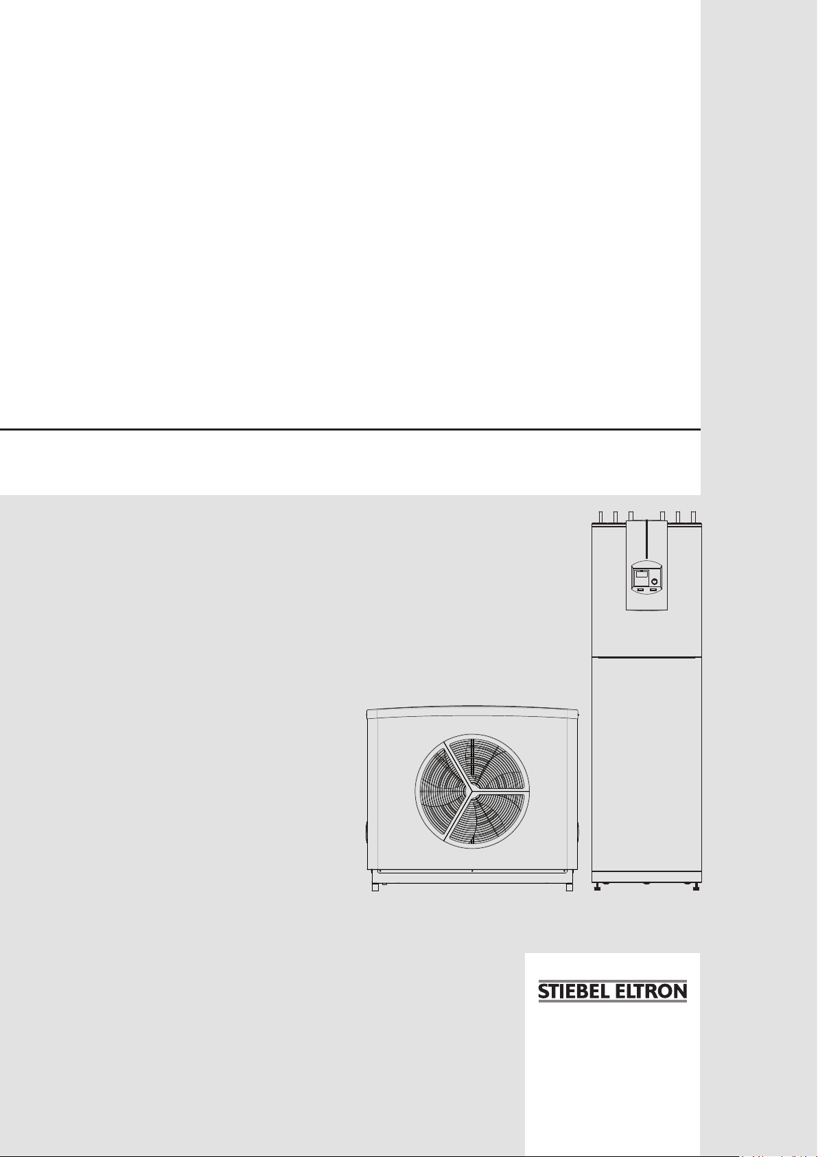
Air | water heat pump
» WPL 15 IKS-2
» WPL 25 IK-2

CONTENTS
SPECIAL INFORMATION
OPERATION
1. General information �����������������������������������������4
1.1 Safety instructions ����������������������������������������������� 4
1.2 Other symbols in this documentation ����������������������� 4
1.3 Units of measurement ������������������������������������������ 4
1.4 Standardised output data �������������������������������������� 4
2. Safety ���������������������������������������������������������� 5
2.1 Intended use ������������������������������������������������������ 5
2.2 General safety instructions ������������������������������������ 5
3. Appliance description ���������������������������������������5
3.1 Energy saving tip ������������������������������������������������ 6
4. Settings �������������������������������������������������������6
4.1 Controls ������������������������������������������������������������ 6
4.2 Essential facts in brief ������������������������������������������ 7
4.3 Adjustments at control level 1 �������������������������������� 8
4.4 Overview of control level 2������������������������������������� 8
4.5 Adjustments at control level 2 �������������������������������� 9
4.6 Remote control FE 7 �������������������������������������������� 18
4.7 Remote control FEK �������������������������������������������� 18
4.8 Internet Service Gateway (ISG) ������������������������������� 18
5. Maintenance and care ������������������������������������� 19
6. Troubleshooting �������������������������������������������� 19
6.1 Other problems ������������������������������������������������� 19
INSTALLATION
7. Safety �������������������������������������������������������� 20
7.1 General safety instructions ����������������������������������� 20
7.2 Instructions, standards and regulations ������������������� 20
8. Appliance description ������������������������������������� 20
8.1 Mode of operation ���������������������������������������������� 20
8.2 Standard delivery ���������������������������������������������� 20
9. Preparations ������������������������������������������������ 20
9.1 Internal unit ������������������������������������������������������ 20
9.2 External unit ����������������������������������������������������� 22
9.3 Refrigerant lines ������������������������������������������������ 23
9.4 Electrical installation������������������������������������������� 24
9.5 Buffer cylinder �������������������������������������������������� 24
10. Appliance installation ������������������������������������� 25
10.1 Internal unit ������������������������������������������������������ 25
10.2 External unit ����������������������������������������������������� 25
10.3 Condensate drain ����������������������������������������������� 27
10.4 Installing supply lines and supply cables ������������������ 28
10.5 Installing refrigerant lines ������������������������������������ 28
10.6 Heating water connection ������������������������������������� 31
10.7 DHW connection ������������������������������������������������ 33
10.8 Operation with buffer cylinder ������������������������������� 33
10.9 Fitting the push-fit connectors ������������������������������� 33
11. Power supply ����������������������������������������������� 34
11.1 General �����������������������������������������������������������34
11.2 Electrical connection of internal unit ����������������������� 34
11.3 Electrical connection of external unit ���������������������� 37
11.4 Connection diagram WPL 15 IKS-2 ��������������������������38
11.5 Connection diagram WPL 25 IK-2 ���������������������������� 39
11.6 Sensor installation ���������������������������������������������� 40
11.7 Remote control FE 7 �������������������������������������������� 40
11.8 Remote control FEK ��������������������������������������������40
11.9 Internet Service Gateway ISG �������������������������������� 41
11.10 Safety temperature controller for underfloor heating
system ������������������������������������������������������������41
12. Commissioning ��������������������������������������������� 41
12.1 Checks before commissioning�������������������������������� 41
12.2 Minimum flow rate ��������������������������������������������� 42
12.3 Setting the flow rate on the heating side ������������������ 42
12.4 Operation and control ����������������������������������������� 43
12.5 Decommissioning ����������������������������������������������� 43
12.6 Heat pump manager commissioning summary ���������� 44
12.7 WPMme commissioning report ������������������������������ 53
13. Settings ����������������������������������������������������� 54
13.1 Standard settings ����������������������������������������������� 54
13.2 Heating and DHW programs ���������������������������������� 54
13.3 Appliance handover �������������������������������������������� 55
14. Shutting down ���������������������������������������������� 55
15. Troubleshooting �������������������������������������������� 55
15.1 Fault display ����������������������������������������������������� 55
15.2 Resetting the high limit safety cut-out ��������������������� 57
15.3 Fan noise ��������������������������������������������������������� 57
15.4 Fault tables �������������������������������������������������������58
16. Maintenance ������������������������������������������������ 60
16.1 DHW cylinders ��������������������������������������������������� 60
16.2 Replacing the signal anodes���������������������������������� 61
16.3 Safety valve drain on the internal unit ��������������������� 61
16.4 Maintenance work on the external unit �������������������� 61
17. Specification ������������������������������������������������ 62
17.1 Dimensions and connections ��������������������������������� 62
17.2 Internal unit wiring diagram WPL 15 IKS-2 ���������������� 66
17.3 Internal unit wiring diagram WPL 25 IK-2������������������68
17.4 External unit wiring diagram WPL 15 IKS-2 and WPL
25 IK-2 ������������������������������������������������������������� 71
17.5 Performance diagram WPL 15 IKS-2 ������������������������ 72
17.6 Performance diagram WPL 25 IK-2 �������������������������� 73
17.7 Data table �������������������������������������������������������� 74
GUARANTEE
ENVIRONMENT AND RECYCLING
2 | WPL 15 IKS | WPL 25 IK www.stiebel-eltron.com

SPECIAL INFORMATION
SPECIAL INFORMATION
- The appliance may be used by children aged8
and up and persons with reduced physical, sensory or mental capabilities or a lack of experience
and know-how, provided that they are supervised
or they have been instructed on how to use the
appliance safely and have understood the resulting risks. Children must never play with the appliance. Children must never clean the appliance
or perform user maintenance unless they are
supervised.
- Use a permanent connection to the power supply.
Ensure the appliance can be separated from the
power supply by an isolator that disconnects all
poles with at least 3mm contact separation.
- Maintain the minimum clearances to ensure trouble-free operation of the appliance and facilitate
maintenance work.
- In dual mode operation, return water from the
second heat generator may flow through the heat
pump. Please note that the return water temperature may be a maximum of 65°C.
- Ensure that the refrigerant circuit is tested once a
year for leaks, in accordance with EC DIRECTIVE
517/2014. The tightness test must be documented
in the log.
DHW cylinders
- Regularly activate the safety valve to prevent
it from becoming blocked e.g. by limescale
deposits.
- Drain the DHW cylinder as described in the chapter „Installation/ Maintenance/ Draining the
DHW cylinder“.
- Install a type-tested safety valve in the cold water
supply line. For this bear in mind that, depending
on the static pressure, you may also need a pressure reducing valve.
- The safety valve discharge aperture must remain
open to the atmosphere.
- Install the safety valve discharge pipe with a
constant fall to the discharge outlet.
- Size the discharge outlet so that water can drain
off unimpeded when the safety valve is fully
opened.
- The air outlet in the knurled cap of the quick-action air vent valve must not point towards the MFG
PCB. Close the quick-action air vent valve again
after venting.
- Maintenance work, such as checking the electrical safety, must only be carried out by a qualified
contractor.
- We recommend a regular inspection (to establish
the current condition of the system), and maintenance by a qualified contractor if required (to
return the system to its original condition).
- Following isolation from the mains supply, parts
of the appliance may remain live for up to 2 minutes since the capacitors still have to discharge
into the inverter.
- Never interrupt the power supply, even outside
the heating period. The system’s active frost protection is not guaranteed if the power supply is
interrupted.
- There is no need to shut the system down in
summer. The heat pump manager has an automatic summer/winter changeover.
www.stiebel-eltron.com WPL 15 IKS | WPL 25 IK | 3
OPERATION
General information
OPERATION
1. General information
The chapters „Special information“ and „Operation“ are intended
for both users and qualified contractors.
The chapter „Installation“ is intended for heating contractors.
Note
Read these instructions carefully before using the appliance and retain them for future reference.
Pass on the instructions to a new user if required.
1.1 Safety instructions
1.1.1 Structure of safety instructions
KEYWORD Type of risk
!
Here, possible consequences are listed that may result
from failure to observe the safety instructions.
Steps to prevent the risk are listed.
1.2 Other symbols in this documentation
Note
Notes are bordered by horizontal lines above and below
the text. General information is identified by the symbol
shown on the left.
Read these texts carefully.
Symbol Meaning
!
This symbol indicates that you have to do something. The ac-
tion you need to take is described step by step.
Material damage
(appliance, consequential and environmental damage)
Appliance disposal
1.3 Units of measurement
Note
All measurements are given in mm unless stated otherwise.
1.1.2 Symbols, type of risk
Symbol Type of risk
!
1.1.3 Keywords
KEYWORD Meaning
DANGER Failure to observe this information will result in serious
WARNING Failure to observe this information may result in serious
CAUTION Failure to observe this information may result in non-seri-
Injury
Electrocution
Burns
(burns, scalding)
injury or death.
injury or death.
ous or minor injury.
1.4 Standardised output data
Explanations to determine and interpret the specified standardised
output data.
1.4.1 EN 14511
The output data specifically mentioned in text, diagrams and
technical datasheets has been calculated according to the test
conditions of the standard shown in the heading of this section.
However, there is a deviation from this norm in the output data for
air/water inverter heat pumps at source temperatures of > -7°C
as this concerns partial load values. The associated percentage
weighting in the partial load range can be found in EN14825 and
EHPA quality label regulations.
Generally, the test conditions stated above will not fully meet the
conditions found at the installation site of the system user.
Depending on the chosen test method and the extent to which
this method deviates from the test conditions defined in the first
paragraph of this section, any deviations can have a considerable
impact.
Further factors that have an influence on the test values are the
measuring equipment, the system configuration, the age of the
system and the flow rates.
A confirmation of the specified output data can only be obtained
if the test conducted for this purpose is also performed in accordance with the test conditions defined in the first paragraph of
this section.
4 | WPL 15 IKS | WPL 25 IK www.stiebel-eltron.com
OPERATION
Safety
2. Safety
2.1 Intended use
The appliance is used for heating rooms and domestic hot water.
Observe the application limits listed in the chapter „Specification/
Data table“.
The appliance is intended for domestic use, i.e. it can be used
safely by untrained persons. The appliance can also be used in a
non-domestic environment, e.g. in a small business, as long as it
is used in the same way.
Any other use beyond that described shall be deemed inappropriate. Observation of these instructions and of instructions for any
accessories used is also part of the correct use of this appliance.
Any changes or conversions to the appliance void any warranty.
2.2 General safety instructions
Observe the following safety instructions and regulations.
- Only qualified contractors should carry out the electrical
work and installation of this appliance.
- The authorised contractor is responsible for adherence to
all currently applicable instructions during installation and
commissioning.
- Operate the appliance only when fully installed and with all
safety equipment fitted.
- Protect the appliance from dust and dirt ingress during building work.
- The DHW cylinder is at mains water pressure. If no diaphragm expansion vessel is installed, expansion water may
drip from the safety valve during heat-up.
- Notify your contractor if water is still dripping from the safety
valve after the heat-up process.
WARNING Burns
There is a risk of scalding at outlet temperatures in
excess of 43 °C.
DANGER Injury
!
The appliance may be used by children aged 8 and up
and persons with reduced physical, sensory or mental
capabilities or a lack of experience provided that they
are supervised or they have been instructed on how to
use the appliance safely and have understood the resulting risks.
WARNING Injury
!
For safety reasons, only operate the appliance with
the casing closed.
3. Appliance description
The appliance comprises an internal unit (heat pump module) and
an external unit (evaporator module).
These two units are connected by refrigerant lines.
The external unit is designed for external installation and extracts
low grade heat from the ambient air.
The extracted energy together with the energy drawn by the variable speed compressor is transferred to the heating water inside
the internal unit.
The heating water then transfers the heat to the heating system or
to the DHW via a three-way valve. As a result, flow temperatures
of 65°C can be achieved.
The appliance is equipped with an electric emergency/booster
heater. In mono mode operation, the electric emergency/booster
heater is activated when the dual mode point can no longer be
maintained, in order to safeguard heating operation and the provision of high DHW temperatures. In mono energetic mode, the
electric emergency/booster heater is activated as a booster heater.
Mode of operation
The heat exchanger on the air side (evaporator) is fitted in the
external unit. It extracts heat from the outdoor air at temperatures
ranging from +40°C to -20°C.
In the heat exchanger on the water side (condenser) the heating
water is heated up to the flow temperature using electric power
(compressor).
At air temperatures below approx.+7°C, the humidity in the air
precipitates as hoarfrost on the evaporator fins. Any hoarfrost is
automatically defrosted. Water created from defrosting collects in
the condensate pan and drains off below the external unit.
Control unit
The system is regulated by an integral, weather-compensated
return temperature control unit (WPMme). The return temperature
control maintains DHW heating at the required temperature level.
The return temperature control is combined with inverter technology. Thanks to this control technology, the compressor output
is matched to the outside temperature and the heat demand of
the building.
This prevents the compressor from being subjected to frequent
cycling, particularly in spring and autumn. Consequently, the average flow temperature is lowered, leading to higher efficiency and
seasonal performance factor.
The status of the signal anode is shown by a red signal indicator
beneath the heat pump manager.
www.stiebel-eltron.com WPL 15 IKS | WPL 25 IK | 5
OPERATION
Settings
Appliance functions
- Fully automatic heating of heating water.
- Suitable for underfloor heating and radiator heating systems;
preferentially for low temperature heating systems, as these
achieve higher performance factors.
- Extraction of energy from outdoor air, even at outside temperatures as low as -20°C.
- Centralised control of the heating system and safety functions
through the heat pump manager.
- Lower average flow temperature and higher seasonal performance factor thanks to intelligent output control.
- Comprises all components and safety equipment required for
operation.
- Compact space requirement due to compact design.
Heat pump manager functions
- System expansion through the FEK and FE7 remote controls.
- Input of the system and heat pump frost protection limits.
- Automatic pump kick control.
- Reset option.
- Stored fault list with precise fault code indication on the dis-
play, including date and time.
- Fast and precise fault diagnosis via system analyser, including
temperature scanning of heat pumps and system without additional equipment.
- Factory settings for time switch programs for all heating and
DHW circuits.
4. Settings
Operation is divided into three control levels. Control levels 1 and
2 are accessible to users and contractors alike. Control level 3 is
reserved for contractors:
Control level 1 (control flap closed)
This enables the adjustment of operating modes, such as standby
mode, programmed operation, constant day or setback mode etc.
Control level 2 (control flap open)
This enables system parameters, such as room temperatures, DHW
temperatures, heating programs etc. to be adjusted.
Control level 3 (for contractors only)
This level is protected by a code and should only be used by a
qualified contractor. Here, you can determine the specific details
regarding the heat pump and the heating system.
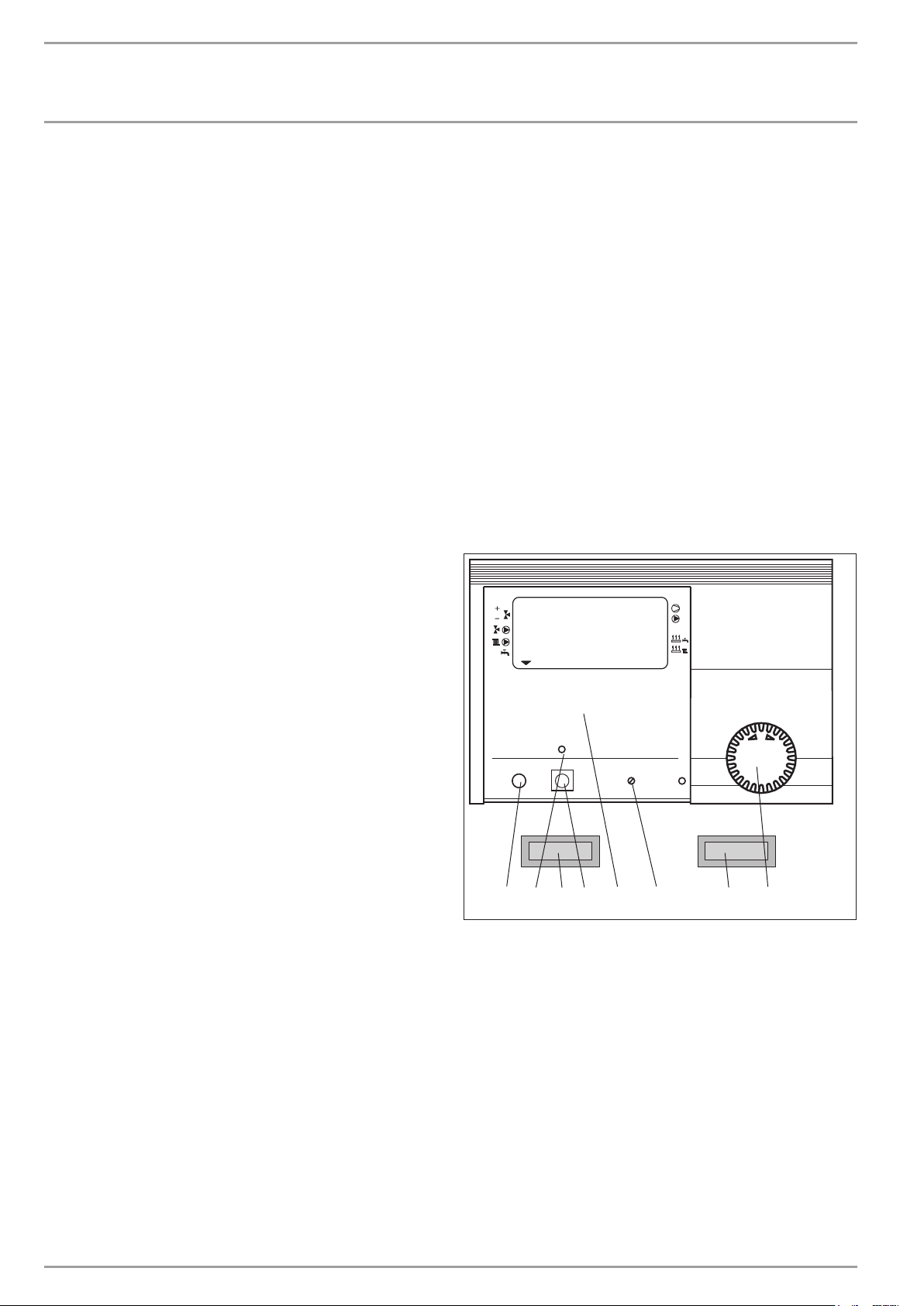
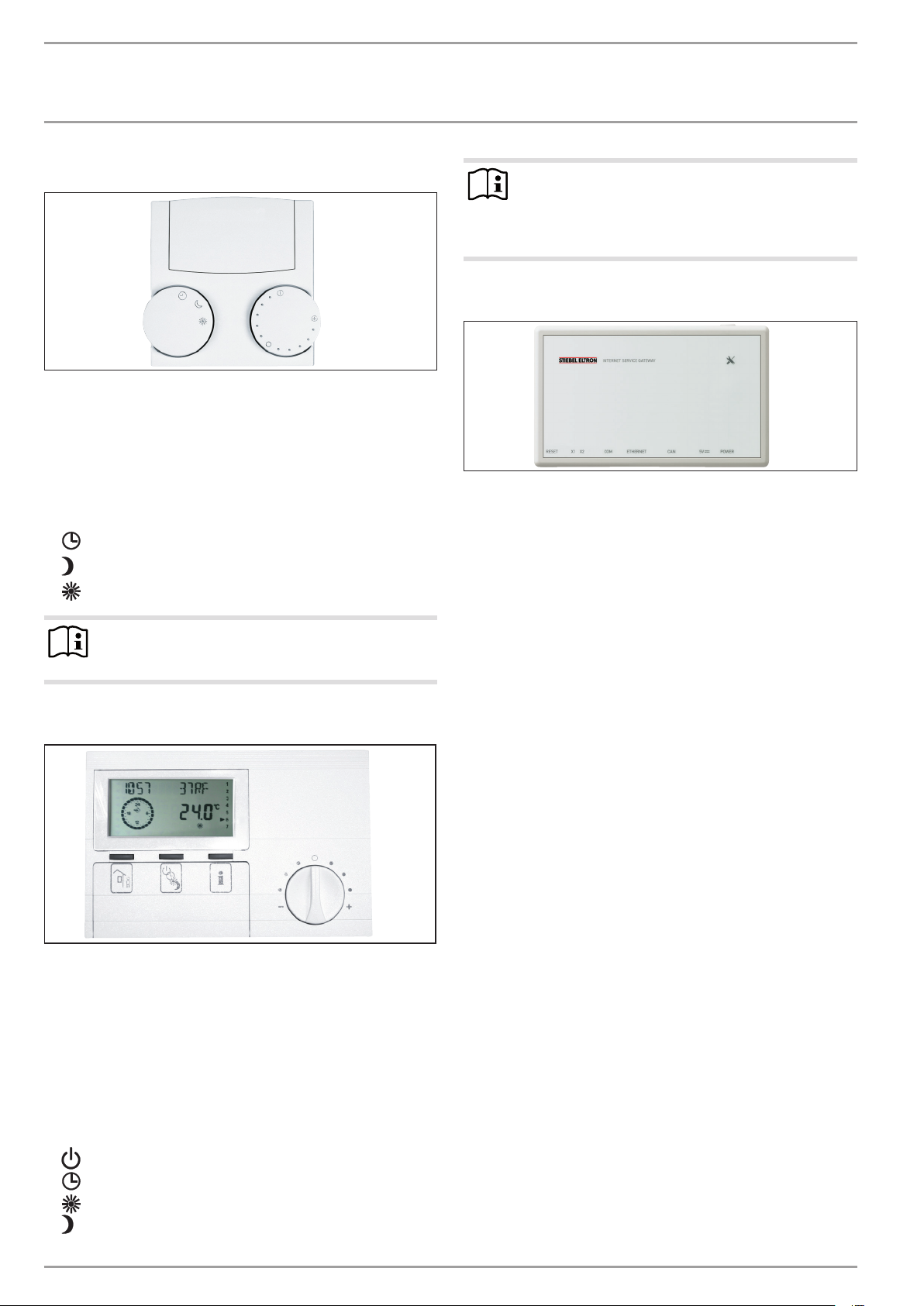
4.1 Controls
4.1.1 Heat pump manager WPMme
ROOM T HC1
3.1 Energy saving tip
Heat pumps operate with particular economy and environmental
responsibility when run at a maximum flow temperature of 35°C.
- Low flow temperatures can be achieved by using area
heating systems (e.g. underfloor heating or wall heating
systems).
- For radiator heating systems size radiators to a maximum
flow temperature of 45°C.
- If the DHW cylinder needs to be heated to 60°C once a day to
ensure pasteurisation, activate parameter PASTEURISATION.
If you have any questions about pasteurisation, please ask
your contractor.
Heizkurven
Zeit / Datum
Info Temperaturen
Ferien / Partyprog.
PRGPC Reset Auto
57
Heizprogramme
Warmwasserprog.
4
Inbetriebnahme
36
8
Raumtemp. 1
Raumtemp. 2
Warmwassertemp.
1 Rotary selector
2 Signal indicator, red (signal anode)
3 Rotary selector Reset / Auto
4 Appliance menu
5 Programming key
6 No function
7 Programming indicator
8 Optical interface RS 232
2
1
26�03�01�0073
6 | WPL 15 IKS | WPL 25 IK www.stiebel-eltron.com
OPERATION
Settings
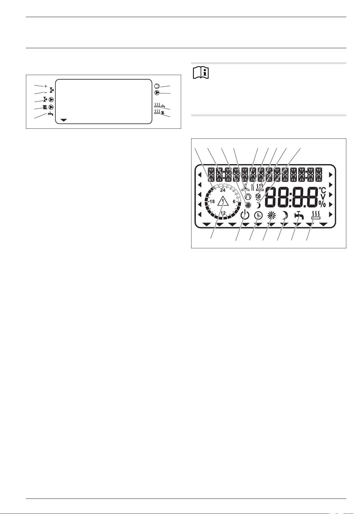
4.1.2 System status display
5
6
7
8
9
1 Compressor
2 Buffer cylinder primary pump
3 Electric emergency/booster heater (DHW heating)
4 Electric emergency/booster heater (heating)
5 Mixer open
6 Mixer closed
7 Circulation pump, heating circuit 2 „mixer circuit“
8 Circulation pump, heating circuit 1 „radiator circuit“
9 DHW heating
ROOM T HC1
1
2
3
4
4.2 Essential facts in brief
Settings
All settings at the heat pump manager follow the same pattern:
Opening the control flap switches the heat pump manager into
programming mode. An arrow appears in the lower section of
the display, above the menu item ROOM TEMPHC1.
Turn the rotary selector to choose a different menu item.
Turn the rotary selector until the arrow is visible above the
menu item you require.
Press the programming key to adjust the values under the
selected menu item.
The values shown on the display can be adjusted when the programming indicator illuminates.
Turn the rotary selector to adjust the displayed value.
Press the programming key again to save the selected values.
The new set value is saved when the programming indicator
goes out.
If the programming indicator above the programming key does
not go out after saving the value, this means that there are further
values that can be set under this menu item.
Press the programming key to adjust the displayed values.
You may only terminate the programming process once the
programming indicator has gone out.
Note
During commissioning, a system check will be implemented, e.g. all sensors that are currently connected are
displayed upon request. Sensors not connected before
the system went 'live' are not registered by the heat pump
manager and are therefore not displayed. The indicator
symbol skips that menu item.
26�03�01�1367
Display including all display elements
2 9876531
16
1 Heating times for central heating and DHW (black)
2 14-digit plain text display
3 Day mode for heating circuit 1
4 Compressor running
5 Silent mode in operation
6 Switching time pairs for heating and DHW mode or with si-
lent mode: Silent mode 1 or 2
7 Emergency/booster heater in operation
8 Defrosting
9 Setback mode for heating circuit 1
10 Electric emergency/booster heater
11 DHW mode
12 Constant setback mode
13 Constant day mode
14 Automatic mode
15 Standby mode
16 Fault message (flashing)
4
15
13 12 11
14
10
D0000057133
Terminating the programming process
Close the control flap to terminate individual menu item
entry and saving processes.
If you want to make further changes, turn the rotary selector
until the display shows BACK.
Press the programming key to return to the previous level.
Closing the control flap while the programming indicator is illuminated returns the heat pump manager to its original state. The
adjusted value will then not be saved.
www.stiebel-eltron.com WPL 15 IKS | WPL 25 IK | 7
OPERATION
!
Settings
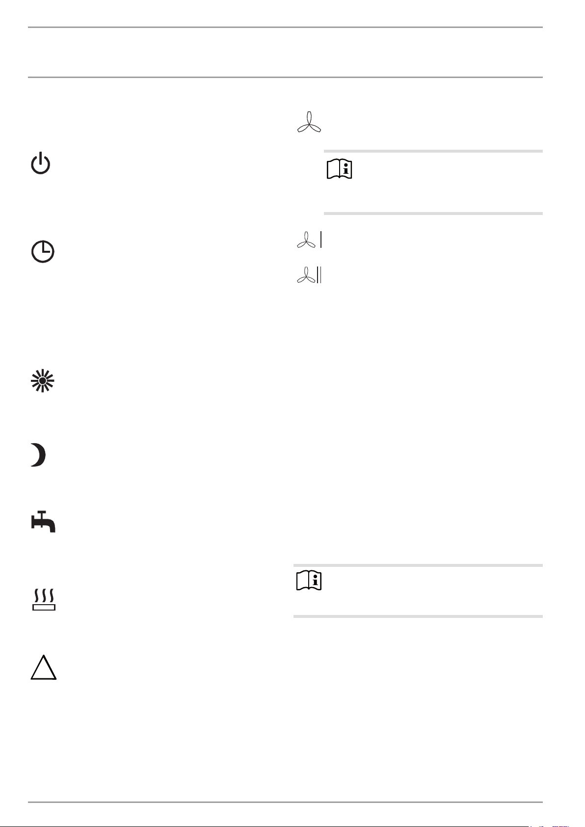
4.3 Adjustments at control level 1
Keeping the control flap closed, turn the rotary selector to
the operating mode you wish to adjust.
Standby mode
Frost protection is activated for heating and DHW mode.
When the flap is closed, FROST PROTECT is displayed. The
set DHW value is fixed at 10°C, the set heating flow value
is calculated based on a set room value of 5°C.
Application: During prolonged periods of absence, e.g.
holidays.
Automatic mode
Heating in line with the time switch program (applies
to heating circuits1 and2). Changeover between day
temperature and setback temperature.
DHW heating in line with the time switch program; changeover between day temperature and setback temperature. With this operating mode, an additional symbol
(sun or moon) indicates in the display, whether heating
circuit1 is currently in day or in setback mode.
The remote control is only active in this operating mode.
Application: When DHW and central heating are required.
Constant day mode
The heating circuit (HC) is constantly held at the day temperature (HC1 and HC2). DHW heating according to time
switch program.
Application: In low energy houses, if no setback mode
intended.
Constant setback mode
The heating circuit is constantly held at the setback temperature (HC1 and HC2). DHW heating according to time
switch program.
Application: During weekends away.
Silent mode
Reduced noise mode
Silent mode is enabled. The associated time programs
determine activation of the fan or compressor throttle.
Note
Silent mode has an effect on the heating output
and efficiency of the heat pump.
When silent mode 2 is active, higher electricity
bills result.
Silent mode 1
The fan and / or compressor run with reduced output.
Silent mode 2
Compressor and fan are stopped. Heat generator2 takes
over heating.
4.4 Overview of control level 2
Control level 2 is accessed as follows:
Open the control flap.
Select the required parameter with the rotary selector. Turn
the rotary selector until the arrow is visible above the menu
item you require.
The selected menu item is displayed as plain text. The arrow indicates the menu position within the control level.
You can now adjust the values for the following menu items (see
following chapters).
ROOM TEMP HC 1
Here you can select the set room temperature for day and setback
mode for heating circuit1.
DHW mode
DHW heating in line with the time switch program; changeover between day temperature and setback temperature. Frost protection is enabled for heating mode.
Application: The heating season has ended; only DHW
should be generated (summer mode).
Electric emergency/booster heater
This setting activates the electric emergency/booster
heater. In this operating mode, the electric emergency/
booster heater provides DHW and room heating, irrespective of the dual mode changeover point.
Fault message (flashing)
This symbol indicates faults in the heat pump system.
Inform your contractor immediately.
ROOM TEMP HC 2
Here you can select the set room temperature for day and setback
mode for heating circuit2. Room T HC2 will only be displayed if
the mixer flow sensor for heating circuit2 has been connected.
Note
The actual room temperature can also be scanned here,
provided the FE7 remote control has been connected and
allocated to HC1 or HC2.
DHW TEMP
Here you can assign a set day and night value for the temperature
in the DHW cylinder.
TIME / DATE
Here you can adjust the time and summer time. At the factory,
summer time is set to begin on 25 March and to end on 25 October.
HOLIDAY/PARTY
You can indicate the length of your holiday using the HOLIDAY
menu item (start date, end date). The heat pump system will operate in setback mode for the selected period. Frost protection for
the DHW cylinder is active.
8 | WPL 15 IKS | WPL 25 IK www.stiebel-eltron.com
OPERATION
Settings
Under the PARTY menu item, you can extend the day mode by a
few hours.
TEMPERATURES
Here you can check the heat pump system sensor temperatures,
comparing set with actual values, check the heating curve gap etc.
HEATING CURVES
Here you can select a heating curve each for heating circuit1 and
heating circuit2. Please note that the room temperature will only
remain constant irrespective of the outside temperature if the
correct heating curve has been selected for the relevant type of
building. Selecting the correct heating curve is therefore vitally
important.
HEATING PROG
Here you can adjust heating programs associated with heating
circuits 1 and 2 (see chapter „Settings / Heating programs“).
DHW PROGRAM
Here you select the times when the appliance will control DHW
heating using the set day value. At all other times, the appliance
controls DHW heating using the set night value (setback mode).
See chapter „Settings / DHW programs“).
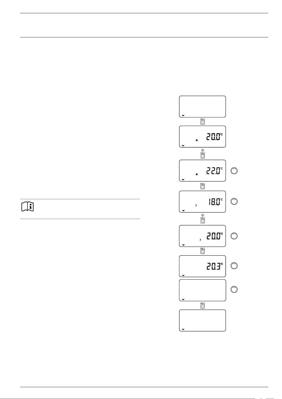
4.5.1 Room temperature, heating circuit 1
With menu item ROOM T HC1, you can select the set room temperature for day and setback mode for heating circuit1. Changing
these parameters results in a parallel shift of the heating curve.
The actual room temperature can also be scanned, as soon as the
FE7 remote control has been connected and allocated to heating
circuit 1.
ROOM T HC1
SET ROOM T DAY
SET ROOM T DAY
COMMISSIONING
Note
The commissioning level (control level 3) may only be
altered by your qualified contractor.
Here the settings of control level2 and the system-specific parameters need to be determined. Your heating contractor or our service department can set the parameters at control level 3, which
is protected by code.
All parameters must be checked by your contractor or our service
department. All selected values should be entered into the relevant column (system value) in the commissioning report.
4.5 Adjustments at control level 2
You can change the values under individual menu items, if required, by using the programming key and the rotary selector.
Follow the instructions in the following diagrams which illus-
trate the process step by step.
Note that the values can only be adjusted when the programming
indicator is illuminated.
Press the programming key again to save the altered set
values.
The values are saved when the programming indicator goes out.
If the programming indicator does not go out after saving the
value, this means that there are further values that can be set
under this menu item.
SET ROOM T NGT
SET ROOM T NGT
ACTUAL ROOM T
BACK
ROOM T HC1
www.stiebel-eltron.com WPL 15 IKS | WPL 25 IK | 9
OPERATION
Settings
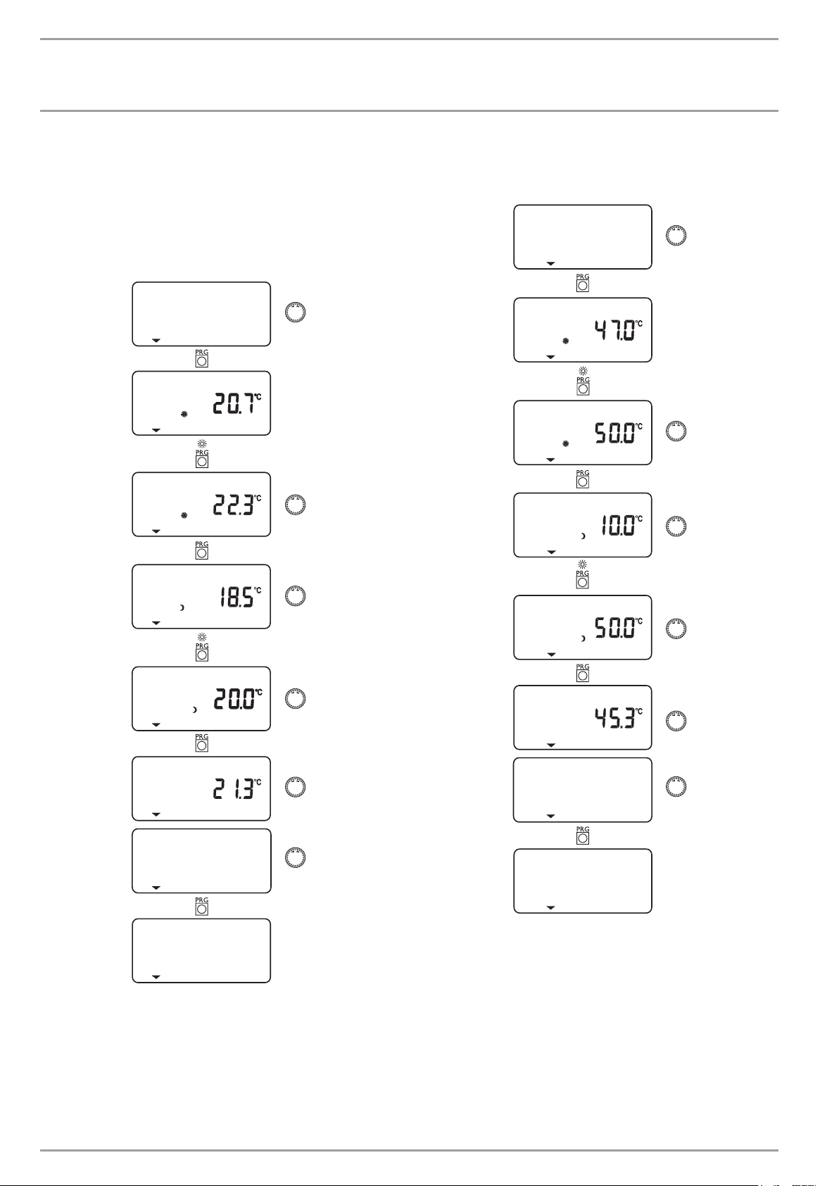
4.5.2 Room temperature, heating circuit 2
With menu item ROOM T HC2, you can select the set room temperature for day and setback mode for heating circuit2. ROOM T
HC2 will only be displayed if the mixer flow sensor is connected.
The actual room temperature can also be scanned, as soon as the
FE7 or FEK remote control has been connected and allocated to
heating circuit2.
ROOM T HC2
SET ROOM T DAY
SET ROOM T DAY
4.5.3 DHW temperature
Under menu item DHW TEMP, you can assign a set day and night
value for the temperature in the DHW cylinder.
DHW TEMP
SET DHW T DAY
SET DHW T DAY
SET HW T NGT
SET ROOM T NGT
SET ROOM T NGT
ACTUAL ROOM T
BACK
ROOM T HC2
SET HW T NGT
ACTUAL DHW T
BACK
DHW TEMP
10 | WPL 15 IKS | WPL 25 IK www.stiebel-eltron.com
OPERATION
Settings
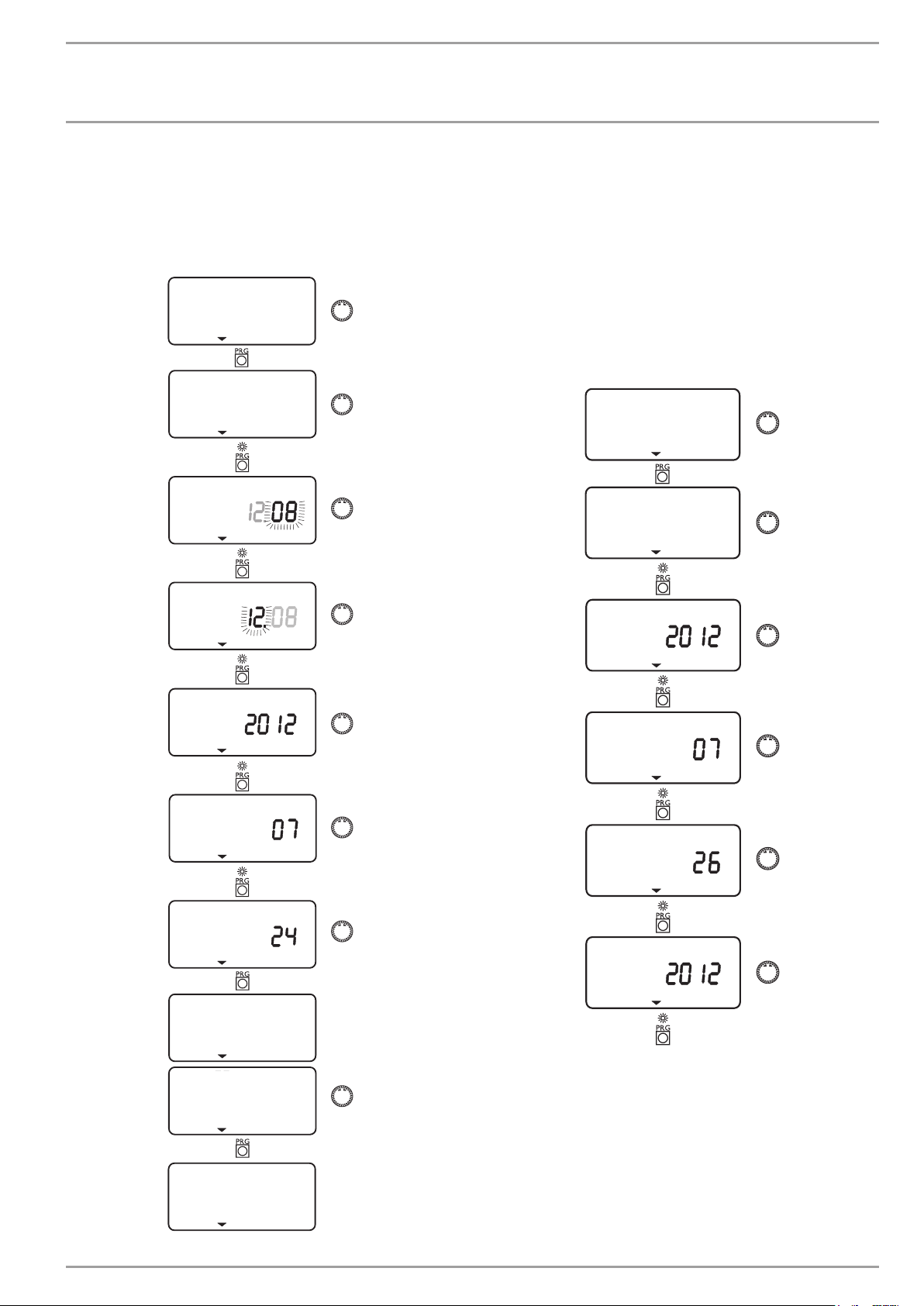
4.5.4 Time and date
You can adjust the time and summer time with the TIME/DATE
menu item.
At the factory, summer time is set to begin on 25 March and to
end on 25 October.
TIME/DATE
SET CLOCK
TIME
TIME
4.5.5 Holiday and party program
In holiday mode, the heat pump system runs in setback mode
and frost protection for DHW heating is enabled. HOLIDAY MODE
is displayed when the flap is closed.
For both the start and end of the holiday, enter the year, month
and day. The start time is 0:00 h on the first day of the holiday. The
end time is 24:00 h on the day the holiday ends. After the holiday
period has expired, the heat pump system switches back to the
previous heating and DHW program.
In party mode, you can extend the day mode for central heating
by a few hours. This is displayed with the flap closed.
HOL PARTY
HOLIDAY
YEAR START
YEAR
MONTH
D AY
SET CLOCK
BACK
MONTH START
DAY START
YEAR END
TIME/DATE
www.stiebel-eltron.com WPL 15 IKS | WPL 25 IK | 11
OPERATION
Settings
MONTH END
DAY END
HOLIDAY
BACK
HOL PARTY
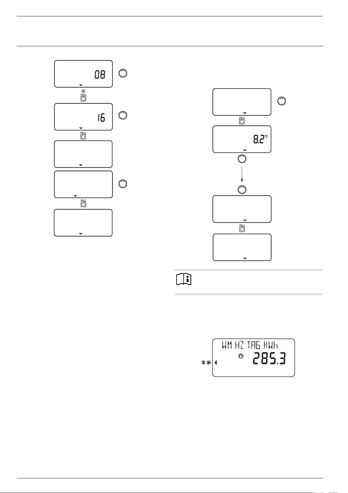
4.5.6 Temperatures
Under menu item TEMPERATURES, you can read off values of the
heat pump and heat pump system.
TEMPERATURES
OUTSIDE
BACK
TEMPERATURES
Note
Please note that actual and set values can only be displayed if the appropriate sensors are connected.
Example:
Amount of compressor heat generated in heating mode since 0:00
h today in kWh.
12 | WPL 15 IKS | WPL 25 IK www.stiebel-eltron.com

OPERATION
Settings
TEMPERATURES Meaning
OUTSIDE Outside temperature
ACT ROOM T FE7 Actual room temperature for heating circuit 1 (HC1) or heating circuit 2 (HC2)
SET ROOM T FE7 Set room temperature for heating circuit 1 or heating circuit 2
REL HUMIDITY Relative humidity (will only be displayed if the FEK remote control is connected)
DEW POINT TEMP Dew point temperature (will only be displayed if the FEK remote control is connected)
ACTUAL DHW T Actual DHW temperature
SET DHW TEMP Set DHW temperature
ACTUAL RTRN T Actual heat pump return temperature for heating circuit 1
ACT HP FLOW T Actual heat pump flow temperature
ACT NGT FLOW T Flow temperature of electric emergency/booster heater
HTG CIRC ACT T Actual heating circuit temperature for heating circuit 1
HTG CIRC SET T Set heating circuit temperature for heating circuit 1 (HC1). Fixed temperature is displayed with set value control.
ACTUAL MIXER T Actual mixer flow temperature for heating circuit 2
SET MIXER TEMP Set mixer flow temperature for heating circuit 2
ACT BUFFER T Actual buffer temperature
FIXED FLOW T Set fixed temperature for heating circuit 1
SET BUFFER T Set buffer temperature (Highest set value of heating circuits H1 and H2. Fixed temperature will be displayed for fixed temperature
DUAL-MODE HTG Dual-mode point - central heating
DUAL-MODE DHW Dual-mode point - DHW
SYST FROST PRO System frost protection temperature
HEATING PRES HEAT ING PRE S
ACT VOLUME Current flow rate [l/min]
MAX VOLUME Flow rate for monitoring the defrost process [l/min]
STATUS HP 1 Status signal for "HP operation" and "HP fault"
STATUS HP 2 Status signal for "HP compressor�ON" and "defrost mode"
ST HP OPERATN Heat pump operation ON/OFF
ST HP COMP Compressor ON/OFF
ST HP FAULT Refrigerant circuit fault ON/OFF (ON= fault, OFF = no fault)
ST HP DEFROST Defrost mode ON/OFF
OUTPUT HP Controller output signal for heat pump output control
INT PUMP RATE Circulation pump output
HEAT AMOU DAY Amount of compressor heat generated in heating mode since 0:00 h today.
(will only be displayed if the FE7 remote control is connected)
(will only be displayed if the FE7 remote control is connected)
control.)
TTL HEAT AMOU Total amount of compressor heat generated in heating mode.
HEAT AMOU DAY Amount of compressor heat generated in DHW mode since 0:00 h today.
TTL HEAT AMOU Total amount of compressor heat generated in DHW mode.
TTL HEAT AMOU Total amount of heat generated by the electric booster heater in heating mode.
TTL HEAT AMOU Total amount of heat generated by electric reheating in DHW mode.
www.stiebel-eltron.com WPL 15 IKS | WPL 25 IK | 13
OPERATION
Settings
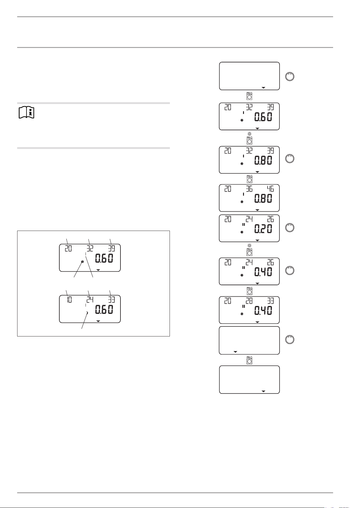
HEATING CURVES
Under HEATING CURVES, you can adjust the respective heating
curves for heating circuits1 and2. It is very important that the
correct heating curve is selected to ensure a constant room temperature.
Note
Your contractor will have set up a building and system-specific optimum heating curve for every heating
circuit. For heating circuit 1 this heating curve relates to
the heat pump return temperature, for heating circuit 2
it relates to the mixer flow temperature.
When the heating curve is displayed on the heat pump manager,
the calculated set return or flow temperature, subject to the outside temperature and the set room temperature, will be shown
at the top of the display.
As soon as a temperature has been preselected via the fixed temperature parameter at control level 3, heating curve1 will be
hidden. If this is the case the display will show FIXED FLOW T with
the relevant temperature.
Adjusting the heating curve
1 32
HTG CURVE
4
1 32
1 Relative to an outside temperature of +20°C
2 Relative to an outside temperature of 0°C
3 Relative to an outside temperature of -20°C
4 Day mode
5 Heating circuit1
6 Setback mode
5
6
26�03�01�1068
BACK
HTG CURVE
14 | WPL 15 IKS | WPL 25 IK www.stiebel-eltron.com
OPERATION
Settings
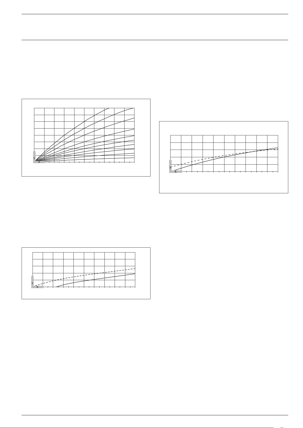
Heating curve diagram
One heating curve each can be adjusted for heating circuit1 and
heating circuit2.
At the factory, heating curve 0.6 is set for heating circuit1 and
heating curve 0.2 for heating circuit2.
These heating curves relate to a set room temperature of 20°C.
-14
-16
-18
2,53
2
1,5
1,2
1
0,8
0,6
0,4
0,2
-20
100
80
60
40
20
2018161412
86420
10
-2-4-6
-8
-10
-12
Y Heating circuit 1, heat pump return temperature [°C]
Heating circuit 2, heat pump flow temperature [°C]
X Outside temperature [°C]
Adjusting the programmed changeover between day mode and
setback mode
The following figure shows a standard heating curve with a slope
of 0.8, relative to a set room temperature for day mode of 20°C.
The lower curve represents the setback curve. For this, the set
room temperature for setback mode of 15°C is used. As a result
the heating curve shifts in parallel.
Adapting a heating curve
Example:
During spring and autumn, it can occur that the temperature in a
building is too low at an outside temperature between 5°C and
15°C, despite open radiator valves, but is OK at outside temperatures of ≤ 0 °C. This problem can be remedied with a parallel shift
and a simultaneous reduction of the heating curve.
Initially, the heating curve was set to 1.0, relative to a set room
temperature of 20 °C. The dotted line indicates the modified heating curve at 0.83 and a modified set room temperature at 23.2°C.
70
60
50
40
30
20
26�03�01�1300�
2018161412
86420
10
-2-4-6
-8
-10
-12
-14
Y Return/flow temperature [°C]
X Outside temperature [°C]
-16
-18
-20
26�03�01�1302�
70
60
50
40
30
20
2018161412
86420
10
Y Return/flow temperature [°C]
X Outside temperature [°C]
1 Day mode
2 Setback mode
-2-4-6
1
2
-8
-10
-12
-14
-16
-18
-20
26�03�01�1301�
www.stiebel-eltron.com WPL 15 IKS | WPL 25 IK | 15
OPERATION
Settings
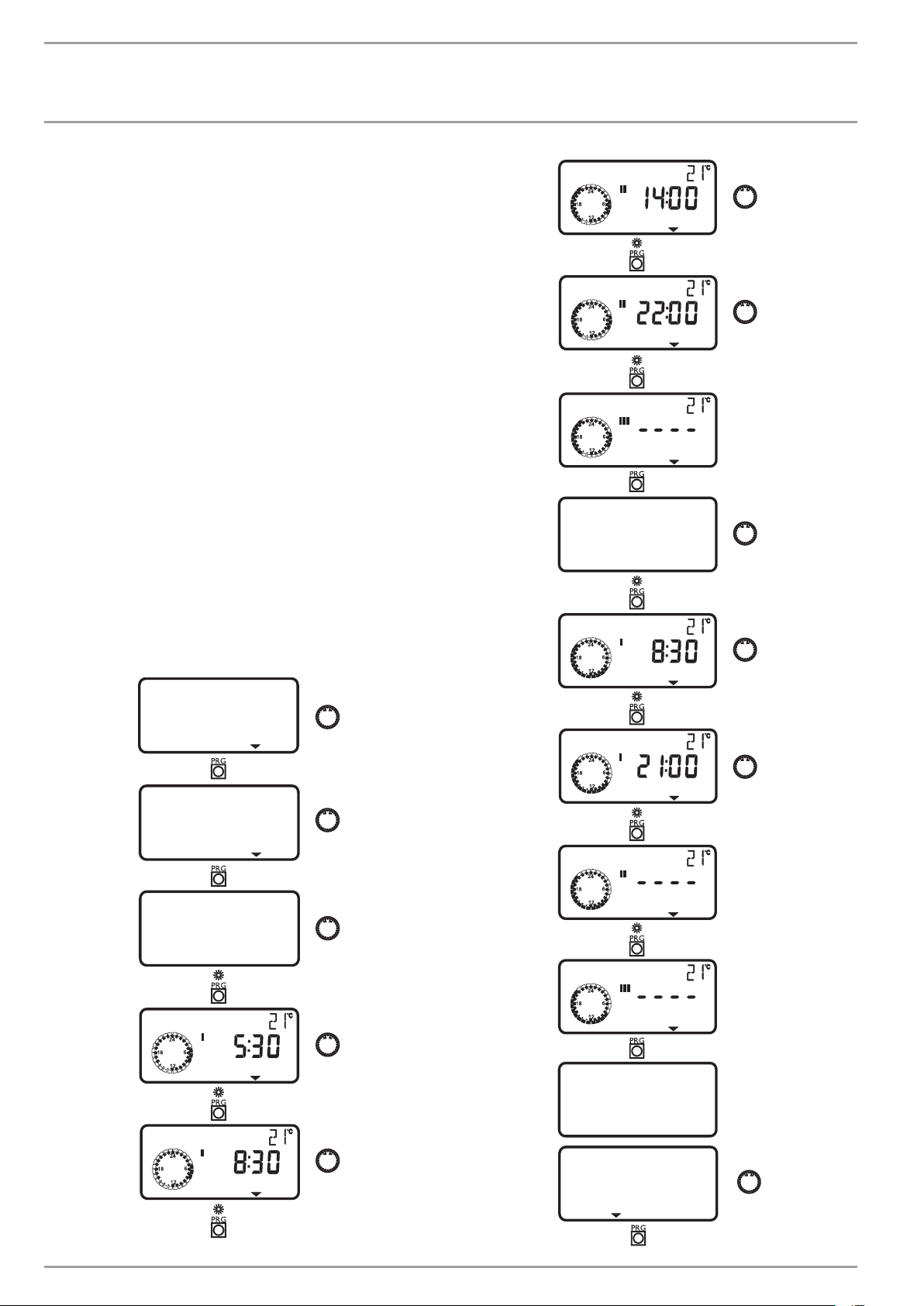
4.5.7 HEATING PROG
The HEATING PROG menu item enables you to determine when
and how often the appliance heats to the set day values for heating
circuit1 and heating circuit2. At all other times, the appliance
heats in setback mode. You will have already selected the set
values under parameter ROOM TEMP HC1/2.
In silent mode 1 you can programme additional times within the
set periods during which you can reduce the compressor output
by up to 50% via the settings. The fan speed is automatically
adjusted.
In silent mode 2 the heat pump is switched off for the entire period
selected here and heating is solely carried out by the electrical
emergency/booster heater.
You can adjust your heating system as follows:
- For each individual day of the week (Monday – Sunday)
- Monday to Friday (Mo – Fr)
- Saturday and Sunday (Sa – Su)
- The whole week (Mo – Su)
You can set three switching time pairs (I, II, III) for each of these
options.
Example:
For heating circuit 1, Monday to Friday, you would like your heating system to provide heat twice a day, i.e. from 05:30 h until 08:30
h and from 14:00 h until 22:00 h. For the weekend, your heating
system should provide heat from 08:30 h until 21:00 h.
HEATING START
HEATING STOP
HEATING START
SAT-SUN
HEATING START
HTG PROG
HEATING CIRC 1
MON-FRI
HEATING START
HEATING STOP
HEATING STOP
HEATING START
HEATING START
SAT-SUN
BACK
16 | WPL 15 IKS | WPL 25 IK www.stiebel-eltron.com
OPERATION
Settings
BACK
HTG PROG
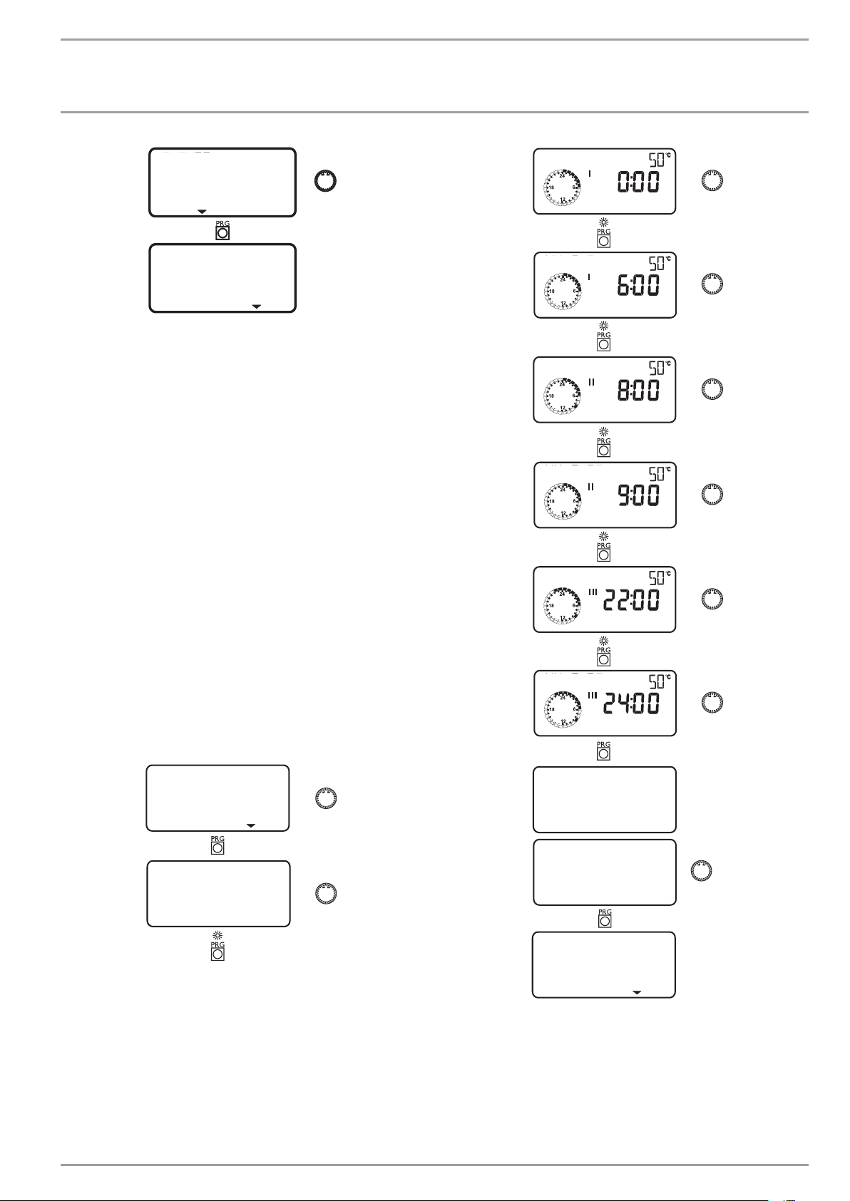
4.5.8 DHW programs
The DHW PROGRAM menu item enables you to adjust the times
for the day and night temperatures for DHW heating.
You can adjust your DHW heating as follows:
- For each individual day of the week (Monday – Sunday)
- Monday to Friday (Mo – Fr)
- Saturday and Sunday (Sa – Su)
- The whole week (Mo – Su)
You can set three switching time pairs (I, II, III) for each of these
options.
Exception: If you want to heat DHW from 22:00 h until 06:00 h the
following day you will need two switching time pairs.
Example:
You would like to heat DHW twice daily, i.e. from 22:00 h until
06:00 h the following day, and then from 08:00 h until 09:00 h.
As the day begins at 00:00 h; you have to begin programming at
00:00 h also for this example.
- The first switching time pair runs from 00:00 h until 06:00 h.
- The second switching time pair runs from 08:00 h until
09:00h.
- The third switching time pair runs from 22:00 h until 24:00 h.
DHW START
DHW STOP
DHW START
DHW STOP
DHW START
DHW STOP
DHW PROGRAM
MON-SUN
www.stiebel-eltron.com WPL 15 IKS | WPL 25 IK | 17
MON-SUN
BACK
DHW PROGRAM
OPERATION
Settings
4.6 Remote control FE 7
With the FE 7 remote control, the following options are available:
- Changing the set room temperature for heating, for heating
circuit1 or2, by ±5°C.
- Changing the operating mode.
The FE 7 remote control features the following controls:
- Rotary selector for changing the set room temperature
- Rotary selector with the following positions
-
Automatic mode
-
Constant setback mode
-
Constant day mode
Note
The remote control is only active in the automatic mode
of the heat pump manager.
4.7 Remote control FEK
Note
The heating curve, room temperature and heating program parameters are not shown at the WPMme heat
pump manager if the FEK is pre-selected for a specific
heating circuit.
4.8 Internet Service Gateway (ISG)
PIC00000609
The Internet Service Gateway (ISG) is an Ethernet gateway in a
wall mounting enclosure and is connected into the LAN (local
area network).
It enables the convenient operation, adjustment and checking of
heat pump system data via the browser of a computer, laptop or
tablet in the local home network.
If required by the customer, appliance data can be automatically
transmitted to the appliance manufacturer‘s Servicewelt portal
via the internet.
Via services, you can access additional options such as system
operation on the go with a smartphone as well as remote setting
of parameters and remote diagnosis, etc.
You can find the current services on our homepage.
PIC00001002
PIC00000704
With the FEK remote control, the following options are available:
- Changing the set room temperature for heating, for heating
circuit1 or2, by ±5°C.
- Changing the operating mode.
The FEK offers the following controls:
- Rotary selector for changing the set room temperature
- „Away“ button
- „Info“ button
- Key to select the following operating modes:
-
Standby mode
-
Automatic mode
-
Constant day mode
-
Constant setback mode
18 | WPL 15 IKS | WPL 25 IK www.stiebel-eltron.com
OPERATION
Maintenance and care
5. Maintenance and care
Material damage
!
Maintenance work, such as checking the electrical safety,
must only be carried out by a qualified contractor.
A damp cloth is sufficient for cleaning all plastic and sheet
metal parts. Never use abrasive or corrosive cleaning agents.
Protect the appliance from dust and dirt ingress during buil-
ding work.
Have the electrical safety of the appliance and the functi-
on of the safety assembly regularly checked by a qualified
contractor.
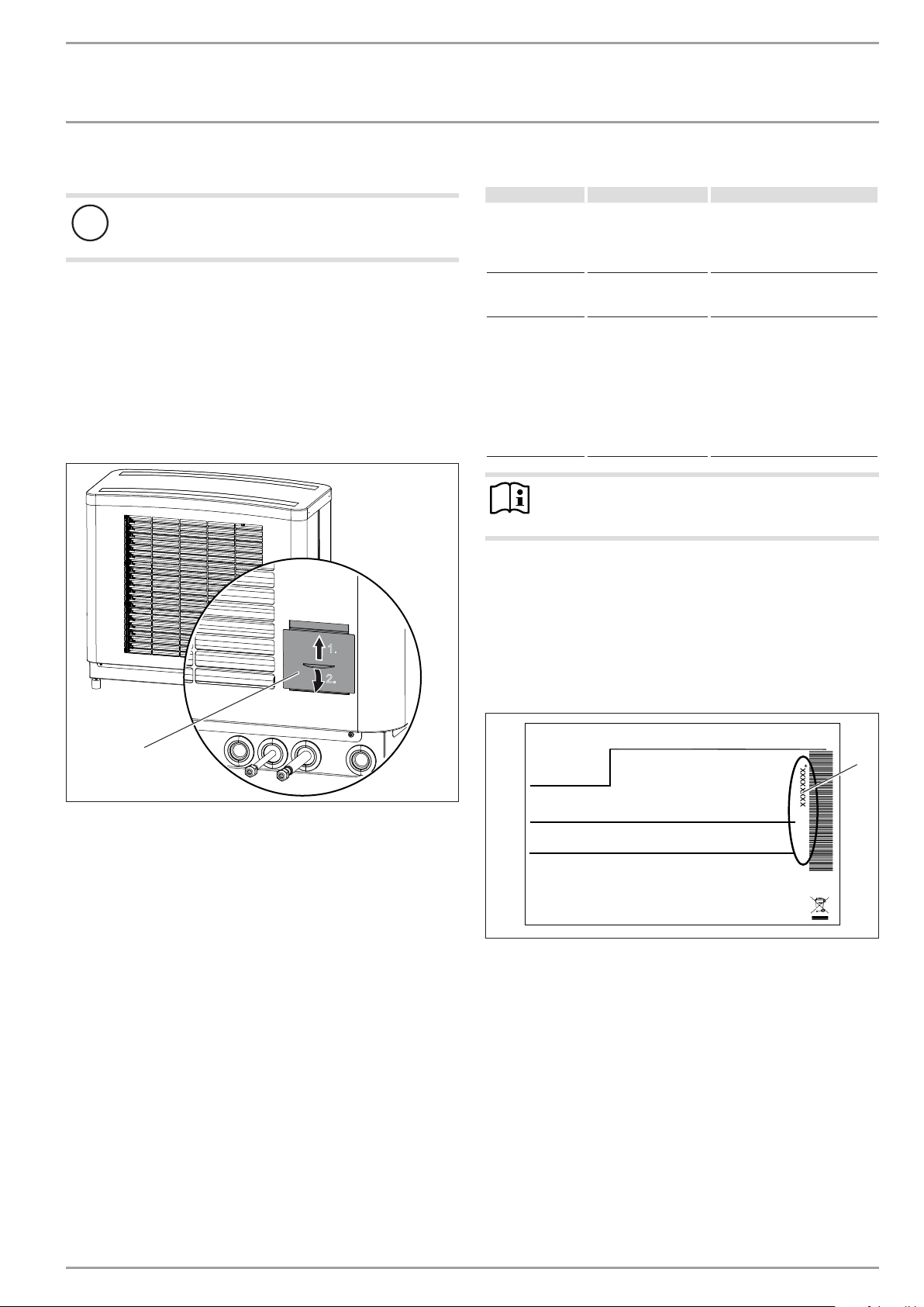
Check the condensate drain monthly (visual inspection). Re-
move contamination and blockages immediately (see chapter
“Maintenance/ Maintenance work on the external unit“).
1.
2.
6. Troubleshooting
Fault Cause Remedy
There is no hot
water or the heating system stays
cold.
Water is leaking
from the appliance.
Condensate is
collecting on the
outside of the appliance.
Note
Even when the condensate is draining away correctly,
expect water to drip from the appliance onto the floor.
6.1 Other problems
If you cannot remedy the fault, notify your heating contractor. To
facilitate and speed up your enquiry, please provide the serial
number from the type plate. The type plate is located at the front
top, on the right or left hand side of the casing.
Sample type plate
There is no voltage at
the appliance.
The condensate drain
may be blocked.
The heat pump is drawing heat from the
outdoor air to heat
the building. This can
cause the humidity
in the outdoor air to
accumulate as dew or
frost on the cooled heat
pump casing. This is not
a defect.
Check the fuses/MCBs in your
fuse box. Replace the fuses/reset
the MCBs if required. Notify your
contractor if the fuses/MCBs
blow/trip again.
Clean the condensate drain as
described in chapter „Maintenance and care“.
1
1 Inspection port
We recommend a regular inspection (to establish the current condition of the system), and maintenance by a qualified contractor if
required (to return the system to its original condition).
D0000056511
Montageanweisung beachten! Dichtheit geprüft!
1 Number on the type plate
Made in Germany
*xxxxxxxxxxxxxxxxxx*
1
26�03�01�1736
www.stiebel-eltron.com WPL 15 IKS | WPL 25 IK | 19
INSTALLATION
Safety
INSTALLATION
7. Safety
Only a qualified contractor should carry out installation, commissioning, maintenance and repair of the appliance.
7.1 General safety instructions
We guarantee trouble-free function and operational reliability
only if the original accessories and spare parts intended for the
appliance are used.
7.2 Instructions, standards and regulations
Note
Observe all applicable national and regional regulations
and instructions.
8. Appliance description
8.1 Mode of operation
The air, which acts as a heat source, enters the external unit.
There, heat is extracted from the outdoor air, so that the air exits
the external unit at a lower temperature.
The energy made usable by the heat pump is transferred to the
heating water inside the internal unit.
The heating water then transfers its energy to the heating circuit.
In addition, the energy of the heating water can also be used to
heat domestic hot water.
The heat from the heating water is transferred to the domestic hot
water by means of a 3-way diverter valve and a heat exchanger.
If the temperature falls below the dual mode point (for example,
-5°C), the electric emergency/booster heater (DHC) starts up.
This occurs when the heat demand exceeds the heating output of
the heating system. The electric emergency/booster heater then
covers the residual heat demand.
The dual mode point can be adjusted by the contractor in the heat
pump manager, under the menu item START UP.
8.2 Standard delivery
8.2.1 Standard delivery, internal unit
Delivered with the appliance:
- 1 outside temperature sensor AFS2
- 4 sliding blocks for the appliance feet
- 4 appliance feet
- 2 flexible pressure hoses
- 2 straight push-fit connectors
- Condensate drain hose
- 4 fixing brackets
8.2.2 Standard delivery, external unit
Delivered with the appliance:
- 4 female soldering connections
8.2.3 Required accessories
- Type-tested safety assembly
Never exceed the operating pressure of 1 MPa.
8.2.4 Further accessories
Also available are refrigerant lines, a corded remote control, immersion and contact sensors as well as a wall mounting panel with
ribbon heater for installing the external unit on a wall.
9. Preparations
9.1 Internal unit
Note
The internal unit is designed for internal installation,
except in wet areas.
Do not position the internal unit underneath or next to bedrooms.
Insulate pipe outlets through walls and ceilings against structure-borne noise transmission.
The room in which the internal unit is to be installed must meet
the following conditions:
- No risk from frost.
- The room must not be subject to a risk of explosions arising
from dust, gases or vapours.
- The room temperature must not exceed 25°C.
- When installing the internal unit in a boiler room together
with other heating equipment, ensure that the operation of
other heating equipment will not be impaired.
- The volume of the installation room should be at least
13.8m³.
- Load-bearing floor (for the weight of the internal unit, see
chapter „Specification / Data table“).
- Make provisions for quiet heat pump operation on floating
screeds.
Isolate the installation surface.
20 | WPL 15 IKS | WPL 25 IK www.stiebel-eltron.com
INSTALLATION
Preparations
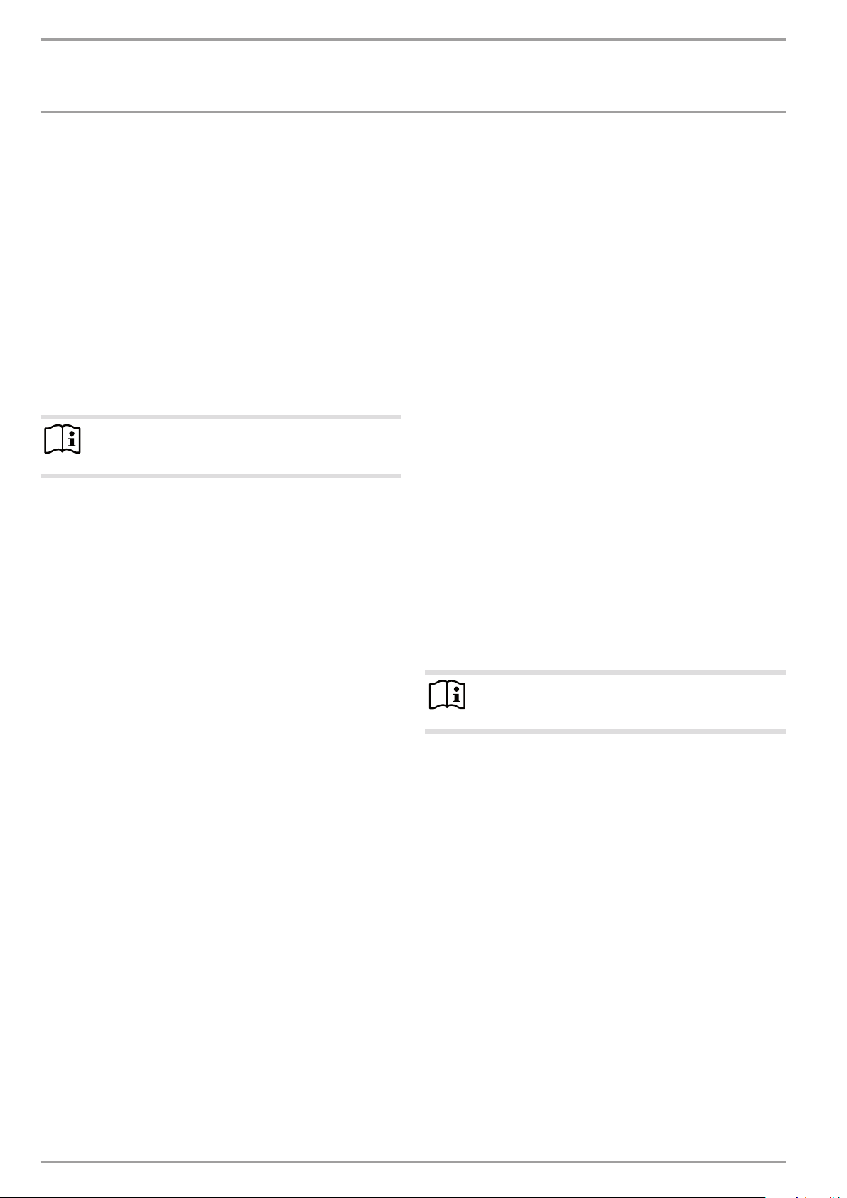
1 2 3 54
Sound attenuation 45dB(A)
Sound attenuation of 45 dB(A) is achieved through a lightweight wall of a timber frame construction with full insulation.
The cross-section of the timber supports should be 60x60mm.
The wall must have plasterboard panelling on both sides, with
12.5mm on one side and 10mm on the opposite side.
1 Concrete base
2 Impact sound insulation
3 Floating screed
4 Floor covering
5 Recess
9.1.1 Sound insulation for rooms adjacent to the installation
room
When the appliance is in operation, sound emissions can occur
which may be a nuisance in adjacent rooms, especially if these
are living rooms or bedrooms. To prevent noise pollution, sound
attenuation measures are necessary, e.g. sound attenuation of a
higher standard for the internal wall. Pipe fixings and wall outlets
must have anti-vibration insulation.
For the wall between the installation room and the living space,
we recommend a wall structure that ensures the following level
of sound attenuation:
- 45dB(A) for adjacent living rooms and bedrooms
- 40dB(A) for other rooms
Doors should be of sound safety category SK3.
If the appliance backs onto an adjacent room, we recommend the
following level of sound attenuation:
- 55dB(A) for adjacent living rooms and bedrooms
- 50dB(A) for other rooms
A passage to the neighbouring room is not recommended.
The floor between the installation room and living room or bedroom must have carefully applied anti-vibration separation. Ensure that no pipes are routed on or in the wall.
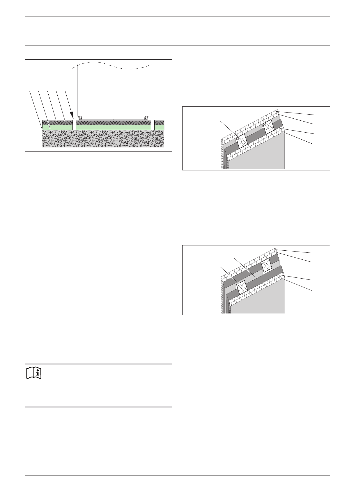
1
26�03�01�1466
1 Timber supports 60 x 60mm
2 Gypsum fibre board 12.5mm
3 Gypsum fibre board 10 mm
Sound attenuation 55dB(A)
Sound attenuation of 55dB(A) is achieved through a lightweight
twin wall of a timber frame construction with full insulation and
30mm parting line. The cross-section of the timber supports
should be 60x60mm. The wall must have 12.5mm plasterboard
panelling on both sides.
2
1
1 Timber supports 60 x 60mm
2 Parting line 30mm
3 Gypsum fibre board 12.5mm
2
3
3
2
D0000047127
3
3
3
3
D0000047126
Hinweis
The appliance can seem loud if operated in an unfinished
building without doors. This is because the fixtures and
fittings are not yet in place which will provide sound attenuation; once the building is occupied this should no
longer occur.
www.stiebel-eltron.com WPL 15 IKS | WPL 25 IK | 21
INSTALLATION
Preparations
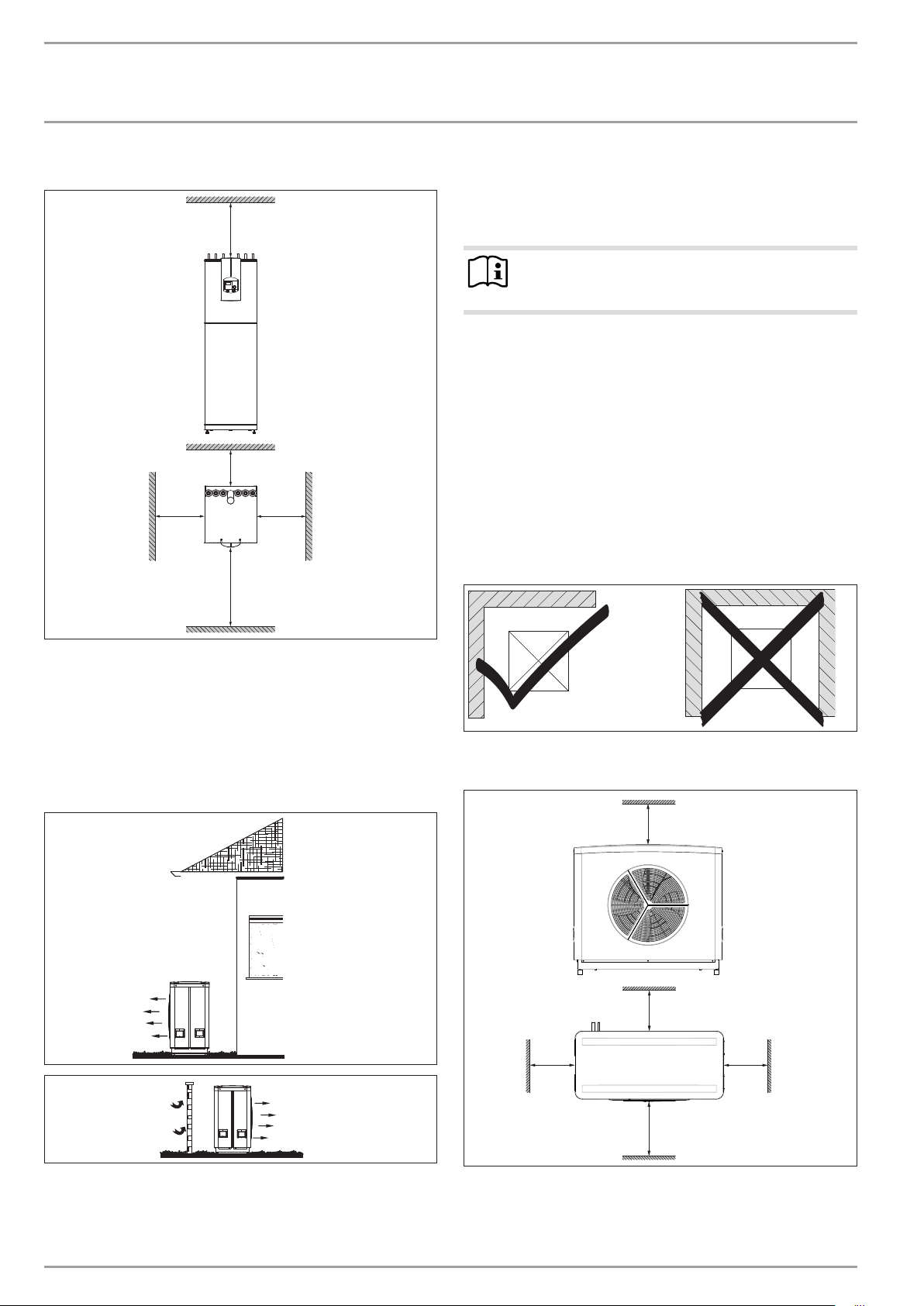
9.1.2 Minimum clearances
≥500
≥300
≥150
≥1500
≥500
9.2.1 Sound emissions
The appliance is louder on the air intake and air discharge sides
than on the two enclosed sides. Observe the following information
when selecting the installation location.
Note
For details regarding the sound power level, see chapter
"Specification / Data table".
- Lawn areas and shrubs help reduce the spread of noise.
- Sound propagation can also be reduced by installing closely
spaced palisade fencing around the appliance.
Ensure that the air intake direction is the same as the main
wind direction. Air should not be drawn in against the wind.
Ensure that the air intake and air discharge are never di-
rected towards noise-sensitive rooms of the house, e.g. bedrooms, or neighbouring houses.
Avoid installation on large, echoing floor areas, e.g. tiled
floors.
Avoid installation between reflective building walls. Reflec-
ting building walls can increase the sound level.
Minimum clearances
Maintain the minimum clearances to ensure trouble-free
operation of the appliance and facilitate maintenance work.
9.2 External unit
The appliance is designed for siting in front of a wall. Observe
the minimum clearances. If the appliance is installed in an open
space or on a roof, protect the air intake side by erecting a wall
to shield it against the wind.
D0000018813
Do not install the appliance in a recess. Two sides of the ap-
pliance must be exposed.
≥800
≥250
D0000043290D0000043059
≥500
≥500
91�00�00�0036
≥2000
The substrate at the installation site must be horizontal, level,
solid and permanent.
Maintain the minimum clearances to ensure trouble-free
operation of the appliance and facilitate maintenance work.
22 | WPL 15 IKS | WPL 25 IK www.stiebel-eltron.com
D0000018802
INSTALLATION
Preparations
Material damage
!
Please note that the outdoor air must be able to flow
unimpeded into the appliance, and the exhaust air must
be able to be expelled without obstruction.
If the air intake and discharge of the appliance are obstructed by surrounding objects, this may cause a thermal
short-circuit.
Ensure that the air intake direction is the same as the main
wind direction. Air should not be drawn in against the wind.
Ensure that the appliance is not surrounded by any objects
such as buildings, walls or fences. If necessary, maintain a
greater clearance to the surrounding objects.
Observe chapter „Sound emissions“.
Material damage
!
The air flow rate through the appliance must not fall
below the minimum level. If the air flow rate falls below
the minimum level, trouble-free operation of the appliance is not guaranteed.
Ensure that the minimum air flow rate is maintained. Obser-
ve the details in chapter „Specification / Data table“.
If necessary, maintain a greater clearance to the surrounding
objects.
If the air discharge side of the appliance faces a wall of the house,
condensate may form on this wall from the cool air at the air
discharge.
Therefore avoid routing refrigerant lines through living areas
and bedrooms.
As much as possible, route refrigerant lines outside the buil-
ding wall.
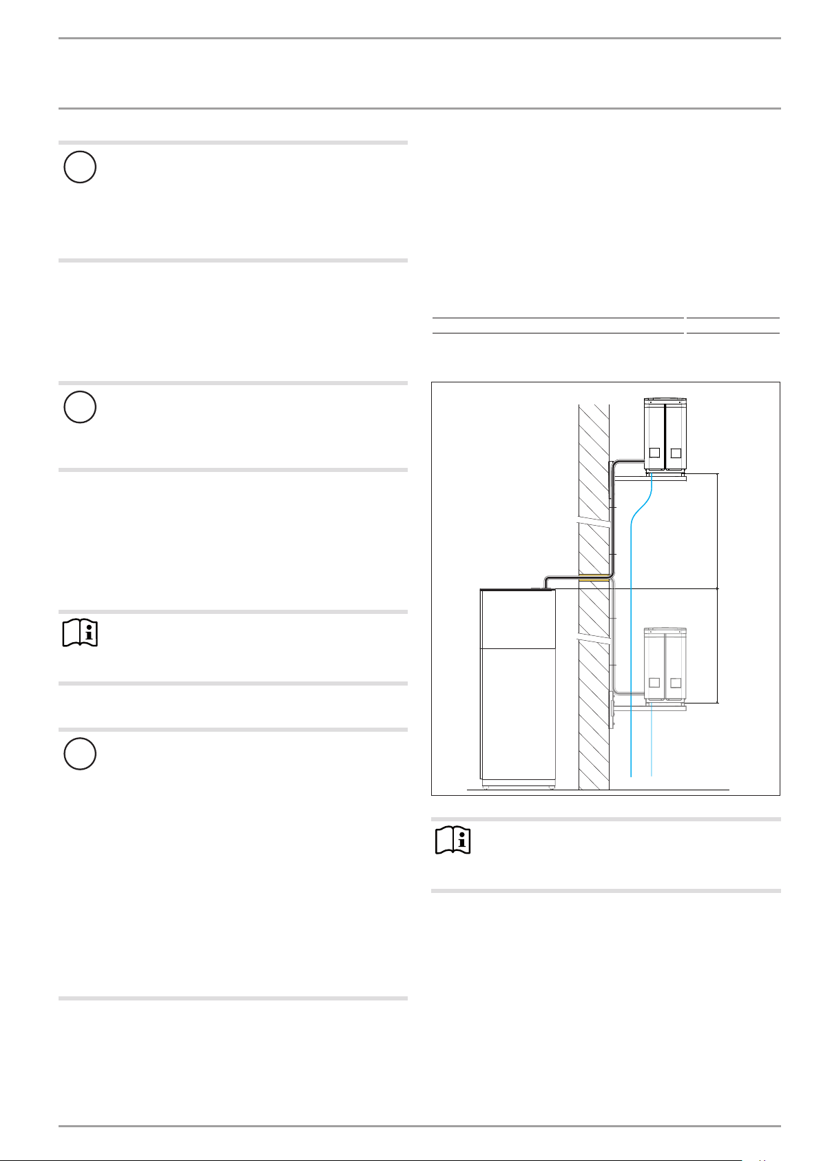
Install both the internal and external unit in such a way that the
maximum lengths and heights of the refrigerant lines are not
exceeded.
Observe the maximum refrigerant line length and the maxi-
mum height offset.
Maximum refrigerant line length 25 m
Minimum refrigerant line length 2 m
Maximum height offset
Note
If the air discharge side faces house walls, maintain the
minimum specified clearance between the appliance and
the building.
9.3 Refrigerant lines
Material damage
!
Prevent dirt and moisture from penetrating the refrigerant circuit. For this purpose, install the refrigerant lines
just before the system is commissioned.
Keep the refrigerant lines closed until commissio-
ning.
Take appropriate measures to prevent damp outdoor
air from penetrating refrigerant lines (e.g. by filling
with dry air/nitrogen and sealing with a plug).
Point the pipe ends downwards to prevent water or
dirt entering.
Cut the pipes using suitable tools without creating
any swarf or burrs. Prevent the ingress of swarf into
the pipes.
Where possible, carry out the installation steps in one go
to prevent any contamination from entering refrigerant
lines between individual steps.
Keep the distance between the external and internal unit as small
as possible to reduce heat losses.
While the appliance is operating you may hear flow noises and
noises from the compressor, particularly during the defrosting
process.
≤5000 ≤5000
Note
The refrigerant does not have to be topped up. The appliance is pre-filled for the maximum permissible split line
length (see chapter "Specification / Data table").
D0000022488
www.stiebel-eltron.com WPL 15 IKS | WPL 25 IK | 23
 Loading...