

STIEBEL ELTRON WPL 07 ACS classic, WPL 17 ACS classic, WPL 09 ACS classic Operation And Installation
OPERATION AND INSTALLAT ION
Air | water heat pump
» WPL 07 ACS classic
» WPL 09 ACS classic
» WPL 17 ACS classic

2 | WPL ACS classic www.stiebel-eltron.com
CONTENTS
SPECIAL INFORMATION
OPERATION
1. General information �����������������������������������������3
1.1 Other relevant documents ������������������������������������� 3
1.2 Safety instructions ����������������������������������������������� 3
1.3 Other symbols in this documentation ����������������������� 4
1.4 Units of measurement ������������������������������������������ 4
1.5 Standardised output data �������������������������������������� 4
2. Safety ���������������������������������������������������������� 4
2.1 Intended use ������������������������������������������������������ 4
2.2 Safety instructions ����������������������������������������������� 4
3. Appliance description ���������������������������������������5
3.1 Minimum software versions ����������������������������������� 5
3.2 Operational characteristics ������������������������������������ 5
3.3 Function ����������������������������������������������������������� 5
4. Settings ������������������������������������������������������� 6
5. Maintenance and care ���������������������������������������6
6. Troubleshooting ����������������������������������������������6
INSTALLATION
7. Safety ���������������������������������������������������������� 7
7.1 General safety instructions ������������������������������������ 7
7.2 Instructions, standards and regulations �������������������� 7
8. Appliance description ���������������������������������������7
8.1 Standard delivery ������������������������������������������������ 7
8.2 Accessories �������������������������������������������������������� 7
9. Preparations �������������������������������������������������� 7
9.1 Sound emissions ������������������������������������������������� 7
9.2 Minimum clearances �������������������������������������������� 8
9.3 Preparation of the installation location ��������������������� 8
9.4 Installing the supply lines ������������������������������������� 10
9.5 WPM heat pump manager ������������������������������������ 10
9.6 Buffer cylinder �������������������������������������������������� 10
9.7 Preparing the electrical installation ������������������������ 11
10. Installation �������������������������������������������������� 11
10.1 Transport ��������������������������������������������������������� 11
10.2 Siting �������������������������������������������������������������� 11
10.3 Flow and return connection ���������������������������������� 12
10.4 Fitting the push-fit connectors ������������������������������� 12
10.5 Heating water connection ������������������������������������� 12
10.6 Oxygen diffusion ������������������������������������������������ 13
10.7 Filling the heating system ������������������������������������ 13
10.8 Minimum flow rate ��������������������������������������������� 13
10.9 Setting the flow rate on the heating side ������������������ 13
10.10 External second heat source ��������������������������������� 14
10.11 High limit safety cut-out for underfloor heating
systems ����������������������������������������������������������� 14
11. Electrical connection ��������������������������������������� 15
11.1 Terminal area ���������������������������������������������������� 15
12. Commissioning ��������������������������������������������� 16
12.1 Checks before commissioning�������������������������������� 16
12.2 Operation with an external second heat source ���������� 16
12.3 Initial start-up ��������������������������������������������������� 16
13. Shutdown ��������������������������������������������������� 17
13.1 Standby mode ��������������������������������������������������� 17
13.2 Power interruption ��������������������������������������������� 17
14. Maintenance ������������������������������������������������ 17
15. Troubleshooting �������������������������������������������� 18
15.1 Checking the IWS DIP switch settings ���������������������� 18
15.2 LEDs (IWS) �������������������������������������������������������� 19
15.3 Reset button ����������������������������������������������������� 19
15.4 Fan noise ��������������������������������������������������������� 20
16. Specification ������������������������������������������������ 21
16.1 Dimensions and connections ��������������������������������� 21
16.2 Wiring diagram ������������������������������������������������� 22
16.3 Connection diagram �������������������������������������������� 24
16.4 Application limit ������������������������������������������������ 26
16.5 Output diagrams WPL 07 ACS classic ����������������������� 27
16.6 Output diagrams WPL 09 ACS classic ����������������������� 28
16.7 Output diagrams WPL 17 ACS classic �����������������������29
16.8 Data table �������������������������������������������������������� 30
GUARANTEE
ENVIRONMENT AND RECYCLING
www.stiebel-eltron.com WPL ACS classic | 3
SPECIAL INFORMATION | OPERATION
General information
SPECIAL INFORMATION
- The appliance may be used by children aged8
and older and persons with reduced physical,
sensory or mental capabilities or a lack of experience and know-how, provided that they are
supervised or they have been instructed on how
to use the appliance safely and have understood
the resulting risks. Children must never play with
the appliance. Children must never clean the appliance or perform user maintenance unless they
are supervised.
- The connection to the power supply must be in
the form of a permanent connection. Ensure the
appliance can be separated from the power supply by an isolator that disconnects all poles with
at least 3mm contact separation.
- Maintain the minimum clearances to ensure trouble-free operation of the appliance and facilitate
maintenance work.
- Maintenance work, such as checking the electrical safety, must only be carried out by a qualified
contractor.
- We recommend an annual inspection (to establish
the current condition of the system), and maintenance by a qualified contractor if required (to
return the system to its original condition).
- Following disconnection from the power supply,
parts of the appliance may remain energised
for 2 minutes until the inverter capacitors have
discharged.
- Never interrupt the heat pump power supply,
even outside the heating season. Otherwise, system frost protection is not guaranteed.
- If the heat pump and frost protection are
completely switched off, drain the system on the
water side.
OPERATION
1. General information
The chapters "Special Information" and "Operation" are intended
for both the user and qualified contractors.
The chapter "Installation" is intended for qualified contractors.
Note
Read these instructions carefully before using the appliance and retain them for future reference.
Pass these instructions on to a new user if required.
1.1 Other relevant documents
Operating and installation instructions for the WPM heat
pump manager
Operating and installation instructions for connected
indoor unit
Operating and installation instructions for mounting
bracket used
Operating and installation instructions for system
components
Commissioning checklist for heat pump
1.2 Safety instructions
1.2.1 Structure of safety instructions
!
KEYWORD Type of risk
Here, possible consequences are listed that may result
from failure to observe the safety instructions.
Steps to prevent the risk are listed.
1.2.2 Symbols, type of risk
Symbol Type of risk
Injury
Electrocution
1.2.3 Keywords
KEYWORD Meaning
DANGER Failure to observe this information will result in serious
injury or death.
WARNING Failure to observe this information may result in serious
injury or death.
CAUTION Failure to observe this information may result in non-seri-
ous or minor injury.
!

OPERATION
Safety
4 | WPL ACS classic www.stiebel-eltron.com
1.3 Other symbols in this documentation
Note
General information is identified by the adjacent symbol.
Read these texts carefully.
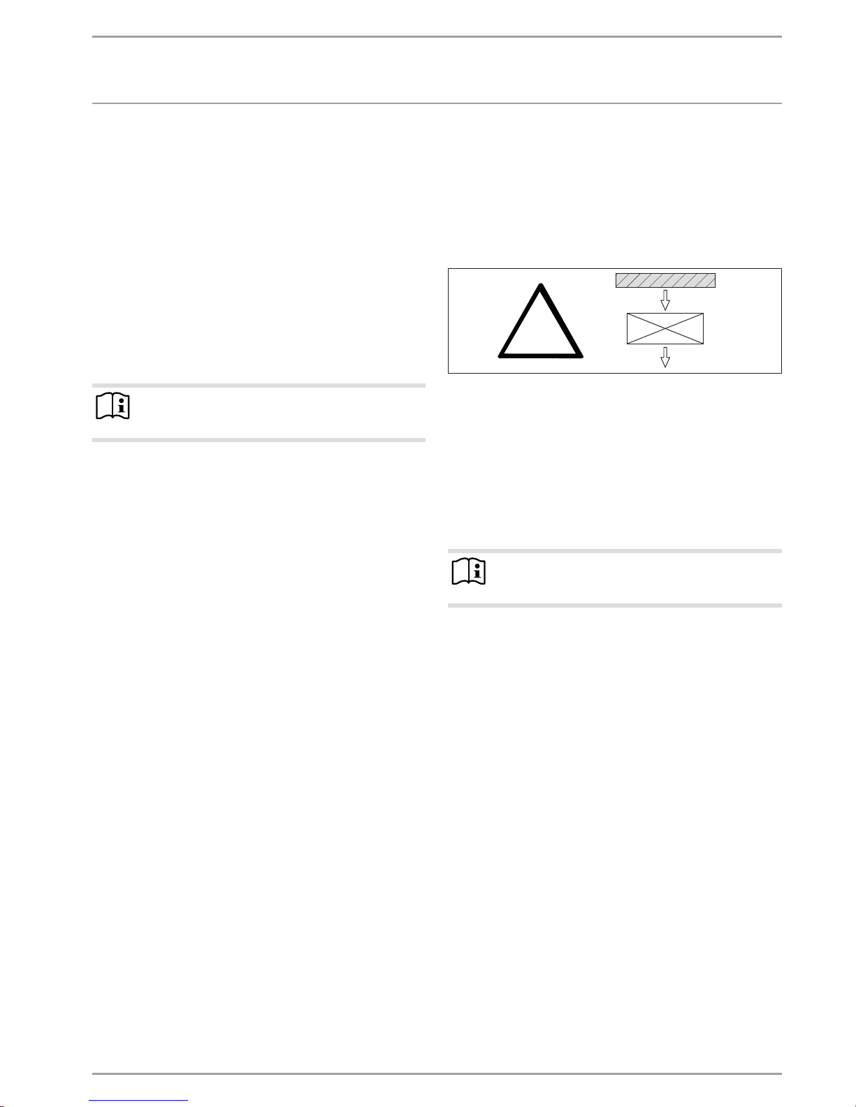
Symbol Meaning
Material losses
(appliance damage, consequential losses and environmental pollution)
Appliance disposal
This symbol indicates that you have to do something. The ac-
tion you need to take is described step by step.
1.4 Units of measurement
Note
All measurements are given in mm unless stated otherwise.
1.5 Standardised output data
Explanations to determine and interpret the specified standardised
output data.
1.5.1 EN 14511
The output data specifically mentioned in text, diagrams and
technical datasheets has been calculated according to the test
conditions of the standard shown in the heading of this section.
However, there is a deviation from this norm in the output data for
air/water inverter heat pumps at source temperatures of > -7°C
as this concerns partial load values. The associated percentage
weighting in the partial load range can be found in EN14825 and
EHPA quality label regulations.
Generally, the test conditions stated above will not fully meet the
conditions found at the installation site of the system user.
Depending on the chosen test method and the extent to which
this method deviates from the test conditions defined in the first
paragraph of this section, any deviations can have a considerable
impact.
Further factors that have an influence on the test values are the
measuring equipment, the system configuration, the age of the
system and the flow rates.
A confirmation of the specified output data can only be obtained
if the test conducted for this purpose is also performed in accordance with the test conditions defined in the first paragraph
of this section.
2. Safety
2.1 Intended use
The appliance is designed for room heating and cooling within
the application limits given in the specification.
This appliance is intended for domestic use. It can be used safely
by untrained persons. The appliance can also be used in non-domestic environments, e.g. in small businesses, as long as it is
used in the same way.
Any other use beyond that described shall be deemed inappropriate. Observation of these instructions and of instructions for any
accessories used is also part of the correct use of this appliance.
2.2 Safety instructions
Observe the following safety instructions and regulations.
- Only qualified contractors may carry out the electrical work
and installation of this appliance.
- The qualified contractor is responsible for adherence to
all currently applicable regulations during installation and
commissioning.
- Operate the appliance only when fully installed and with all
safety equipment fitted.
- Protect the appliance from dust and dirt ingress during
building work.
!
WARNING Injury
The appliance may be used by children over 8 years of
age and persons with reduced physical, sensory or mental capabilities or a lack of experience and expertise,
provided that they are supervised or they have been
instructed on how to use the appliance safely and have
understood the potential risks. Children must never play
with the appliance. Children must never clean the appliance or perform user maintenance unless they are
supervised.
!
WARNING Injury
For safety reasons, only operate the appliance with
the casing closed.
!
OPERATION
Appliance description
www.stiebel-eltron.com WPL ACS classic | 5
3. Appliance description
3.1 Minimum software versions
The following minimum software versions are required for operating the heat pump:
- WPM: 390.09
- MFG: V.14
- FES: 417.05
3.2 Operational characteristics
The appliance is an air | water heat pump that operates as a heating heat pump for outdoor installation. Heat is extracted from the
outdoor air at a low temperature level, and is then transferred to
the heating water at a higher temperature. The heating water can
be heated up to a flow temperature of 60°C.
This appliance has further operational characteristics:
- Suitable for underfloor heating systems.
- Preferred for low temperature heating systems.
- Extracts heat from the outdoor air even at outside temperatures of -20°C.
- Corrosion-protected, external casing made from hot-dipped
galvanised sheet steel plus stove-enamelled finish.
- Filled with non-combustible safety refrigerant.
Note
The appliance may only be used in conjunction with the
following products:
- Hydraulic module HM(S) (Trend) (BE)
- Cylinder and hydraulic module HSBB200(S)classic(BE)
- Integral cylinder HSBC 200 (S) (BE)
3.3 Function
3.3.1 Heating
Heat is extracted from the outdoor air via the heat exchanger
(evaporator) on the air side. The evaporated refrigerant is compressed by a compressor. This process requires electrical energy. At this point, the refrigerant is at a higher temperature level.
A further heat exchanger (condenser) transfers the heat to the
heating circuit. The refrigerant then expands again and the cycle
restarts from the beginning.
At air temperatures below approx. 7°C, the humidity in the air
condenses as hoarfrost on the evaporator fins. Any hoarfrost is
automatically defrosted. The resulting water flows out of the appliance via the free condensate drain and seeps away into the
gravel bed.
!
Material losses
In the defrost cycle, the fan is switched off and the heat
pump circuit is reversed. The heat required for defrosting
is drawn from the buffer cylinder. For operation without a
buffer cylinder, observe chapter "Operation/ Menu structure/ Menu SETTINGS/ STANDARD SETTING/ BUFFER
OPERATION" in the operating and installation instructions
of the WPM. Otherwise the heating water freezes under
unfavourable conditions.
Note
In winter, icicles can form on the bottom of the condensate drain. This does not interfere with the operation
of the appliance, provided the condensate can drain off
unimpeded.
The heat pump automatically reverts to heating mode at the end
of the defrost cycle.
!
Material losses
In dual mode operation, return water from the second
heat source may flow through the heat pump. Please note
that the return temperature must be no higher than 60°C.
3.3.2 Cooling
!
Material losses
The heat pump is not suitable for continuous, year-round
cooling.
Observe the application limits (see chapter "Specifi-
cation/ Data table").
Note
The HM(S) (Trend) (BE) is equipped for both area and
fan cooling.
The HSBB 200 (S) classic (BE) and HSBC 200 (S) (BE) can
provide area cooling.
Rooms are cooled by reversing the heat pump circuit. Heat is
extracted from the heating water. The evaporator transfers this
heat to the outdoor air.
Area cooling requires the installation of the FEK remote control
unit in a reference room to capture the relative humidity and the
room temperature as part of dew point monitoring.
Fan cooling requires the installation of the FE7 remote control
unit in a reference room to capture the relative humidity and the
room temperature as part of dew point monitoring. Similarly, it
is necessary to install a buffer cylinder.
Heat pump application limit
The heat pump is switched off if the outside temperature falls
below the selected lower application limit for cooling (LIMITCOOLING parameter).
OPERATION
Settings
6 | WPL ACS classic www.stiebel-eltron.com
4. Settings
The system is operated exclusively with the WPM heat pump manager. The heat pump manager is installed in the products required
as accessories (see chapter “Installation/ Appliance description/
Accessories”).
Observe the heat pump manager operating and installation
instructions.
5. Maintenance and care
!
Material losses
Maintenance work, such as checking the electrical safety,
may only be carried out by a qualified contractor.
A damp cloth is sufficient for cleaning all plastic and sheet metal
parts. Never use abrasive or corrosive cleaning agents.
Protect the appliance from dust and dirt ingress during
building work.
!
Material losses
Keep the air discharge and intake apertures free from
snow and leaves.
We recommend regular inspection (to establish the current condition of the system), and maintenance by a qualified contractor
if required (to return the system to its original condition).
6. Troubleshooting
Fault Cause Remedy
There is no hot
water or the
heating system
stays cold.
No power at the appliance.
Check the fuses/MCBs in your
fuse box/distribution panel. Replace the fuses/reset the MCBs
if required. Notify your qualified
contractor if the fuses/MCBs
blow/trip again.
Condensate
collects on the
outside of the
appliance and on
the air grille.
The heat pump is extracting heat from the outdoor
air to heat the building.
This can cause the humidity in the outdoor air
to accumulate as dew or
frost on the cooled heat
pump casing. This is not
a defect.
The fan runs
when the
compressor is
switched off.
At outside temperatures
below 10°C, the fan is
regularly started at the
lowest speed when the
compressor is idle. This
prevents the evaporator
and fan from freezing
or icing up due to water
draining off. At temperatures above the freezing
point, the time between
two defrost cycles is increased, thereby improving overall efficiency.
The appliance
produces rhythmic scraping or
grinding noises.
Ice has formed on the air
grille, on the fan blades
or in the air routing.
Call your qualified contractor
(see chapter “Installation/ Troubleshooting/ Fan noises”).
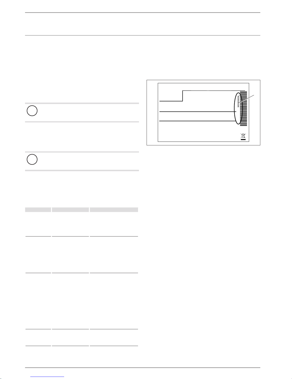
If you cannot remedy the fault, notify your qualified contractor. To
facilitate and speed up your request, provide the number from the
type plate. The type plate is located at the front top, on the right
or left hand side of the casing.
Sample type plate
Montageanweisung beachten! Dichtheit geprüft!
Made in Germany
*xxxxxxxxxxxxxxxxxx*
26�03�01�1736
1
1 Number on the type plate
INSTALLATION
Safety
www.stiebel-eltron.com WPL ACS classic | 7
INSTALLATION
7. Safety
Only a qualified contractor should carry out installation, commissioning, maintenance and repair of the appliance.
7.1 General safety instructions
We guarantee trouble-free function and operational reliability only
if original accessories and spare parts intended for the appliance
are used.
7.2 Instructions, standards and regulations
Note
Observe all applicable national and regional regulations
and instructions.
WPL07ACSclassic| WPL09ACSclassic
The tested appliance conforms to IEC 61000-3-3.
WPL17ACSclassic
The tested appliance conforms to IEC 61000-3-12.
8. Appliance description
The appliance offers frost protection for the connection lines. The
integral frost protection circuit starts the circulation pump in the
heat pump circuit automatically at a condenser temperature of
8°C, and thereby ensures circulation in all water-carrying sections. When the temperature in the buffer cylinder falls to below
+5°C, the heat pump is automatically started subject to the outside temperature.
8.1 Standard delivery
The following are delivered with the appliance:
- Wiring diagram
8.2 Accessories
8.2.1 Required accessories
- T-support SK 2 or wall mounting support WK 1
With integral emergency/booster heater
- Hydraulic module HM(S) (Trend), cylinder and hydraulic
module HSBB 200 (S) classic or integral cylinder HSBC 200 (S)
Without integral emergency/booster heater
- Hydraulic module HMSTrendBE, cylinder and hydraulic module HSBB200SclassicBE or integral cylinder
HSBC200SBE
8.2.2 Further accessories
- Remote control for heating systems FEK
- Remote control for heating systems FE7
- High limit safety cut-out for underfloor heating systems
STB-FB
9. Preparations
!
D0000060163
The appliance is designed for installation on a T-support or wall
mounting support. Observe the minimum clearances. If the appliance is installed in an open space, protect the air intake side. Do
this by erecting a wall to shield it against the wind. A gravel bed
is an essential requirement for both installation versions.
9.1 Sound emissions
The appliance is louder on the air intake and air discharge sides
than on the two enclosed sides. Observe the following information
when selecting the installation location.
Note
For details regarding the sound power level, see chapter
"Specification / Data table".
- Lawn areas and shrubs help reduce the spread of noise.
- Sound propagation can also be reduced by installing closely
spaced palisade fencing around the appliance.
Ensure that the air intake direction is the same as the domi-
nant wind direction. Air should not be blown out against the
wind.
Ensure that the air intake and air discharge are never direct-
ed towards noise-sensitive rooms of the house, e.g. bedrooms, or neighbouring houses.
Avoid installation between reflective building walls. Reflect-
ing building walls can increase the noise level.
INSTALLATION
Preparations
8 | WPL ACS classic www.stiebel-eltron.com
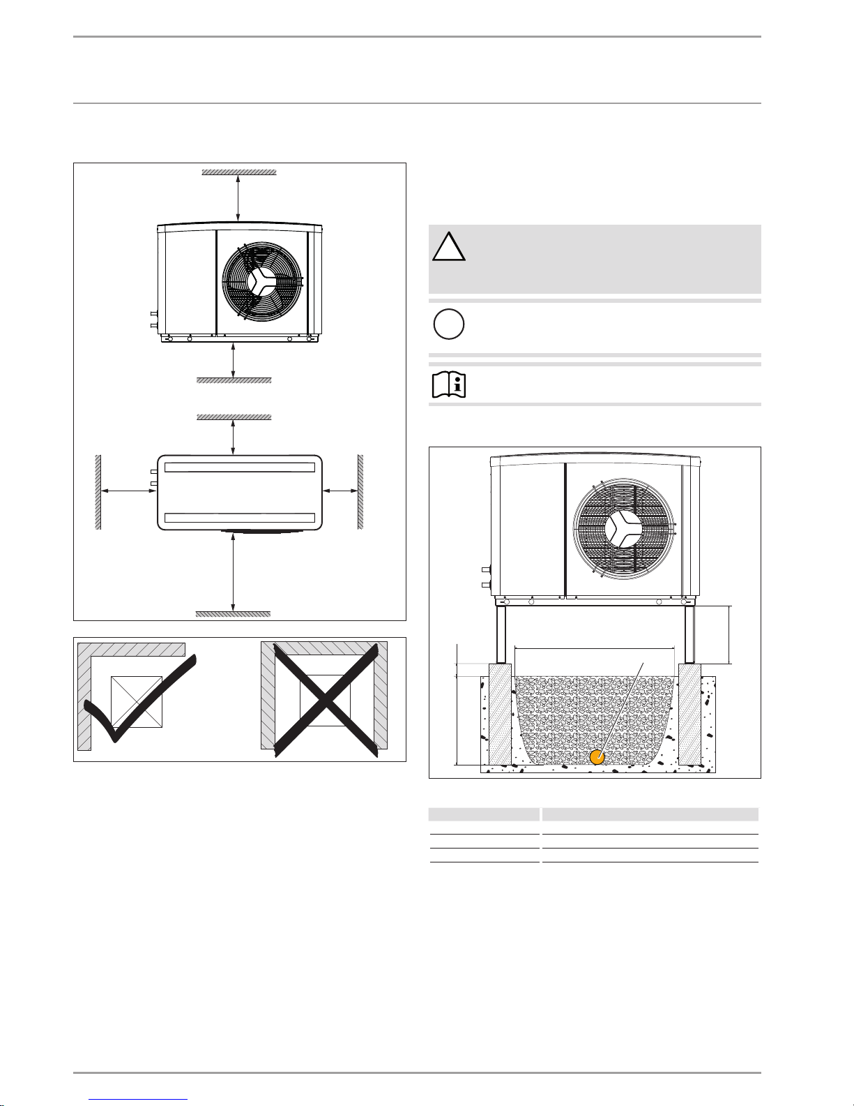
9.2 Minimum clearances
≥2000
≥500
≥200 ≥300
≥1000
≥800
D000005758191�00�00�0036
Never install the appliance in a recess. Two sides of the ap-
pliance must remain exposed.
Maintain the minimum clearances to ensure trouble-free op-
eration of the appliance and facilitate maintenance work.
9.3 Preparation of the installation location
Observe chapter "Sound emissions".
Ensure that the appliance is accessible from all sides.
9.3.1 Condensate drain
!
WARNING Injury
At temperatures below freezing point, ice may form.
Do not allow the gravel bed or surrounding area to
slope downwards towards paths.
!
Material losses
The foundations of the building must have a damp proof
membrane.
Note
Never use grit for the gravel bed.
Example: Gravel bed under T-support SK 2
>800
100
300
a
D0000063484
1
1 Drainage pipe
Heat pump a
WPL 07 ACS classic 700
WPL 09 ACS classic 700
WPL 17 ACS classic 830
Lay a drainage pipe under the appliance to drain moisture
away from the building.
Create a gravel bed below the condensate drain of the
appliance.
INSTALLATION
Preparations
www.stiebel-eltron.com WPL ACS classic | 9
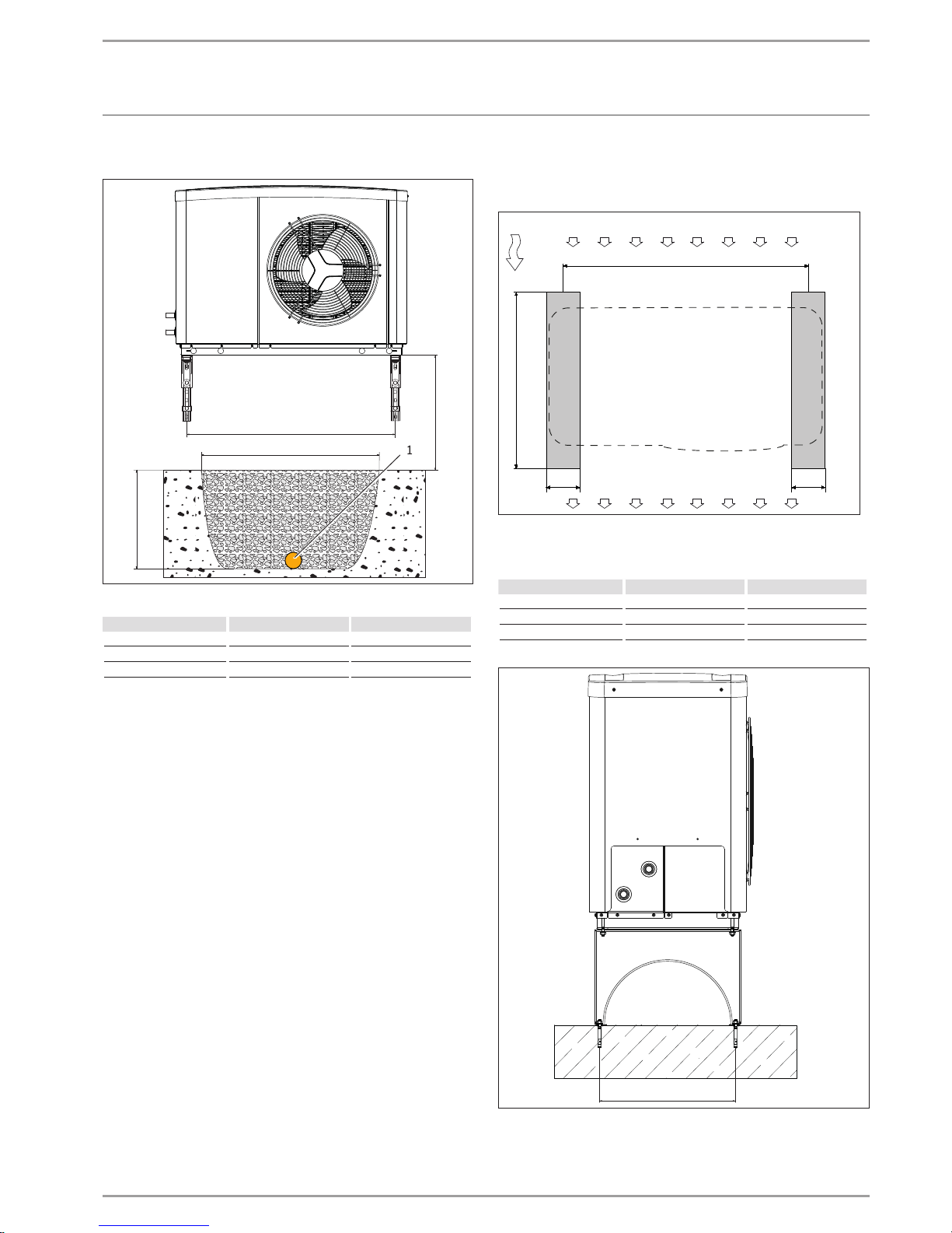
Example: Gravel bed under wall mounting support WK 1
>800
≥300
a
b
D0000065666
1
1 Drainage pipe
Heat pump a b
WPL 07 ACS classic 900 865
WPL 09 ACS classic 900 865
WPL 17 ACS classic 1000 995
Lay a drainage pipe under the appliance to drain moisture
away from the building.
Create a gravel bed below the condensate drain of the
appliance.
9.3.2 Siting
Example: T-support SK 2
B
A
1
3
2
150150
D0000063486
1 Air intake side
2 Air discharge side
3 Main wind direction
Heat pump A B
WPL 07 ACS classic 865 500
WPL 09 ACS classic 865 500
WPL 17 ACS classic 995 500
418
D0000065624
INSTALLATION
Preparations
10 | WPL ACS classic www.stiebel-eltron.com
!
Material losses
The T-support may bend if the heat pump is subject to
any lateral load.
Do not exert any pressure on the sides of the heat
pump.
Observe the static limits of the T-support used.
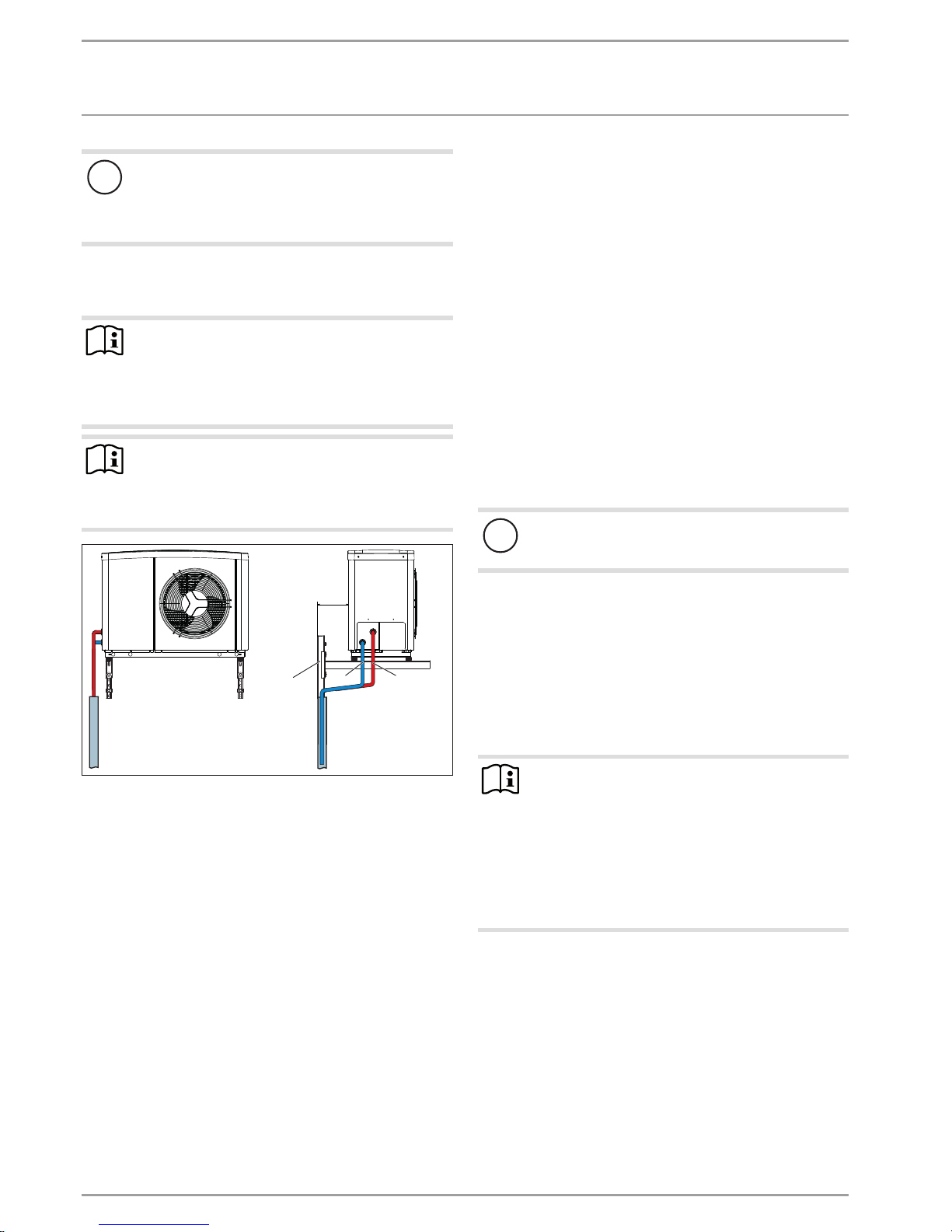
Example: Wall mounting support WK 1
Note
To prevent disturbance due to structure-borne noise
transmission, never install the wall mounting support
on the external walls of living areas or bedrooms.
Install the wall mounting support on a garage wall,
for example.
Note
Condensate drips from the appliance onto the floor.
Observe the minimum clearance below the appli-
ance (see chapter "Preparations/ Minimum clearances").
≥200
2
3
1
D0000057582
1 Heating flow
2 Heating return
3 Wall mounting support
Observe the static limits of the wall mounting support used.
9.4 Installing the supply lines
The supply lines are all electric cables plus the heating flow and
return lines.
Use only weatherproof cables, e.g. NYY.
Protect the flow and return lines against frost with sufficient
thermal insulation. Provide thermal insulation in accordance
with applicable regulations.
Also protect all supply lines/cables against humidity, damage
and UV radiation by means of a conduit.
Protect all pipe fixings and external wall ducts with anti-vi-
bration insulation.
9.5 WPM heat pump manager
A WPM heat pump manager is required to operate the appliance.
This controls the entire heating system. The heat pump manager
is installed in the products defined as required accessories (see
chapter "Installation/ Appliance description/ Accessories").
9.6 Buffer cylinder
!
Material losses
A buffer cylinder with diffusion-proof insulation is essential for fan cooling.
A buffer cylinder is recommended to ensure trouble-free appliance
operation.
The buffer cylinder provides hydraulic separation of the volume
flows in the heat pump circuit and heating circuit, and also serves
as an energy source for defrosting.
When operating without a buffer cylinder, observe the details
specified in chapter "Minimum flow rate with individual room
control by means of FEK/ FE7 in systems without buffer
cylinder".
Note
For operation without a buffer cylinder, we recommend
installing an electric emergency/booster heater (DHC).
An emergency/booster heater is installed in some of the
products required as accessories (see chapter “Installation/ Appliance description/ Accessories”).
If you do not install an emergency/booster heater,
for fault-free operation activate the WW LEARNING
FUNCTION parameter in the WPM heat pump manager.
 Loading...