


STIEBEL ELTRON WPL 13 basic, WPL 20 basic, WPL 18 S basic, WPL 13 S basic Operation And Installation
OPERATION AND INSTALLAT ION
Air source heat pump
» WPL 13 basic
» WPL 20 basic
» WPL 13 S basic
» WPL 18 S basic

CONTENTS
SPECIAL INFORMATION
OPERATION
1. General information �����������������������������������������3
1.1 Further applicable documents �������������������������������� 3
1.2 Safety instructions ����������������������������������������������� 3
1.3 Other symbols in this documentation ����������������������� 4
1.4 Units of measurement ������������������������������������������ 4
1.5 Standardised output data �������������������������������������� 4
2. Safety ���������������������������������������������������������� 4
2.1 Intended use ������������������������������������������������������ 4
2.2 General safety instructions ������������������������������������ 4
2.3 Test symbols ������������������������������������������������������ 4
3. Appliance description ���������������������������������������4
3.1 Function ����������������������������������������������������������� 5
4. Settings �������������������������������������������������������5
5. Maintenance and care ���������������������������������������5
6. Troubleshooting ����������������������������������������������5
INSTALLATION
7. Safety ���������������������������������������������������������� 6
7.1 General safety instructions ������������������������������������ 6
7.2 Instructions, standards and regulations �������������������� 6
8. Appliance description ���������������������������������������6
8.1 Standard delivery ������������������������������������������������ 6
8.2 Accessories �������������������������������������������������������� 6
9. Preparations �������������������������������������������������� 6
9.1 Acoustic emissions ���������������������������������������������� 6
9.2 Minimum clearances �������������������������������������������� 7
9.3 Preparing the installation site��������������������������������� 8
9.4 Electrical installation������������������������������������������� 10
9.5 Buffer cylinder �������������������������������������������������� 10
10. Mounting ���������������������������������������������������� 10
10.1 Handling ���������������������������������������������������������� 10
10.2 Positioning ������������������������������������������������������� 10
10.3 Heating water connection ������������������������������������� 11
10.4 Flow rate, heating side ���������������������������������������� 12
10.5 Condensate drain ����������������������������������������������� 13
10.6 Checking the condensate drain ������������������������������13
10.7 2. Heat source ��������������������������������������������������� 14
10.8 Safety temperature controller for underfloor heating
system ������������������������������������������������������������14
11. Electrical connection ��������������������������������������� 14
11.1 Fitting casing components ������������������������������������ 16
11.2 Routing air hoses ����������������������������������������������� 18
11.3 Fitting air hoses ������������������������������������������������� 19
11.4 Thermally insulating the wall outlets ����������������������� 19
12. Commissioning ��������������������������������������������� 20
12.1 Checks before commissioning�������������������������������� 20
12.2 Commissioning �������������������������������������������������� 20
12.3 Settings ����������������������������������������������������������� 21
13. Taking the appliance out of use �������������������������� 22
13.1 Standby ����������������������������������������������������������� 22
13.2 Power interruption ��������������������������������������������� 22
14. Appliance handover ���������������������������������������� 22
15. Troubleshooting �������������������������������������������� 22
15.1 Elements on the IWS ������������������������������������������� 22
15.2 Cleaning the condensate drain ������������������������������� 23
15.3 Resetting the high limit safety cut-out ��������������������� 23
15.4 Fan noise ��������������������������������������������������������� 23
16. Maintenance ������������������������������������������������ 23
17. Specification ����������������������������������������������� 24
17.1 Connections and dimensions, basic external
installation ������������������������������������������������������� 24
17.2 Connections and dimensions, standard external
installation ������������������������������������������������������� 24
17.3 Connections and dimensions, internal installation ������ 25
17.4 Wiring diagram WPL basic standard appliance (3phase) ������������������������������������������������������������� 26
17.5 Wiring diagram WPL S basic (1-phase) ��������������������� 28
17.6 Output diagrams WPL 13 basic �������������������������������30
17.7 Output diagrams WPL 20 basic ������������������������������� 31
17.8 Output diagrams WPL 13 S basic ����������������������������32
17.9 Output diagrams WPL 18 S basic ���������������������������� 33
17.10 Data table �������������������������������������������������������� 34
GUARANTEE
ENVIRONMENT AND RECYCLING
2 | WPL basic | WPL S basic www.stiebel-eltron.com
SPECIAL INFORMATION | OPERATION
General information
SPECIAL INFORMATION
- The appliance may be used by children aged 8
and up and persons with reduced physical, sensory or mental capabilities or a lack of experience provided that they are supervised or they
have been instructed on how to use the appliance
safely and have understood the resulting risks.
Children must never play with the appliance. Children must never clean the appliance or perform
user maintenance unless they are supervised.
- Only use a permanent connection to the power
supply. The appliance must be able to be separated from the power supply by an isolator that
disconnects all poles with at least 3mm contact
separation.
- Maintain the minimum clearances to ensure trouble-free operation of the appliance and facilitate
maintenance work.
- Maintenance work, such as checking the electrical safety, must only be carried out by a qualified
contractor.
- We recommend an annual inspection (to establish
the current condition of the system), and maintenance by a contractor if required (to return the
system to its original condition).
- The heat pump power supply must not be interrupted, even outside the heating season. Otherwise the system is at risk from frost.
- The heat pump manager automatically switches
the heat pump to summer or winter mode.
OPERATION
1. General information
The chapters „Special Information“ and „Operation“ are intended
for both the user and qualified contractors.
The chapter entitled “Installation” is intended for qualified contractors.
Note
Read these instructions carefully before using the appliance and retain them for future reference.
Pass on the instructions to a new user if required.
1.1 Further applicable documents
Operating and installation instructions of the heat pump
manager WPM
Operating and installation instructions of all other com-
ponents in the system
1.2 Safety instructions
1.2.1 Structure of safety instructions
KEYWORD Type of risk
!
Here, possible consequences are listed that may result
from failure to observe the safety instructions.
Steps to prevent the risk are listed.
1.2.2 Symbols, type of risk
Symbol Type of risk
!
Injury
Electrocution
- If the heat pump and frost protection are completely switched off, drain the system on the
water side.
www.stiebel-eltron.com WPL basic | WPL S basic | 3
1.2.3 Keywords
KEYWORD Meaning
DANGER Failure to observe this information will result in serious
injury or death.
WARNING Failure to observe this information may result in serious
injury or death.
CAUTION Failure to observe this information may result in non-
serious or minor injury.
OPERATION
Safety
1.3 Other symbols in this documentation
Note
Notes are bordered by horizontal lines above and below
the text. General information is identified by the symbol
shown on the left.
Read these texts carefully.
Symbol
!
This symbol indicates that you have to do something. The ac-
tions you need to take are described step by step.
Damage to the appliance and environment
Appliance disposal
1.4 Units of measurement
Note
All measurements are given in mm unless stated otherwise.
1.5 Standardised output data
Explanations to determine and interpret the specified standardised
output data.
1.5.1 Standard: EN 14511
The output data specifically mentioned in text, diagrams and
technical datasheets has been calculated according to the test
conditions of the standard shown in the heading of this section.
Generally, these standardised test conditions will not fully meet
the conditions found at the installation site of the system user.
Depending on the chosen test method and the extent to which
this method deviates from the conditions defined in the norm
shown in the heading of this section, any deviations can have a
considerable impact.
Further factors that have an influence on the test values are the
measuring equipment, the system configuration, the age of the
system and the flow rates.
A confirmation of the specified output data can only be obtained
if the test conducted for this purpose is also performed in accordance with the conditions defined in the norm shown in the
heading of this section.
2. Safety
Only qualified contractors should carry out installation, commissioning, maintenance and repair of the appliance.
Contractors are responsible for adherence to all currently applicable regulations during installation and commissioning.
2.1 Intended use
The appliance is intended to heat buildings and domestic hot water
(DHW). The appliance is designed for extracting energy from the
air and utilising this energy in water-based heating systems within
the stated operating temperature range.
This appliance is designed for domestic use. It can be safely operated by untrained personnel. The appliance can also be used in a
non-domestic environment, e.g. in a small business, as long as it
is used in the same way.
Any other use beyond that described shall be deemed inappropriate. Observation of these instructions is also part of the correct use
of this appliance. Any changes or modifications to this appliance
void all warranty rights.
2.2 General safety instructions
Observe the following safety instructions and regulations.
- The electrical installation and installation of the heating circuit must only be carried out by a recognised, qualified contractor or by our customer service engineers
- Contractors are responsible for adherence to all currently applicable regulations during installation and commissioning.
- Operate the appliance only when fully installed and with all
safety equipment fitted
- Protect the appliance from dust and dirt ingress during
building work
WARNING Injury
!
The appliance may be used by children aged 8 and up
and persons with reduced physical, sensory or mental
capabilities or a lack of experience provided that they
are supervised or they have been instructed on how to
use the appliance safely and have understood the resulting risks. Children must never play with the appliance.
Children must never clean the appliance or perform user
maintenance unless they are supervised.
2.3 Test symbols
See type plate on the appliance.
3. Appliance description
The appliance is an air source heat pump that operates as a heating
heat pump. H eat is extracted from the outdoo r air at a low temperature
level, and is then transferred to the heating water at a higher level.
The heating water can be heated up to a flow temperature of 75 °C.
The appliance is equipped with an electric booster heater (DHC).
The electric booster heater is activated if the dual mode point is
not achieved in mono mode operation in order to ensure the heating operation and the availability of high DHW temperatures. In
such cases the electric booster heater is activated as an additional
heat source in mono energetic operation.
4 | WPL basic | WPL S basic www.stiebel-eltron.com
OPERATION
Settings
Further operational characteristics:
- Suitable for underfloor and radiator heating systems
- Still extracts heat from the outdoor air at – 20 °C outside
temperature
- Corrosion-protected, external casing components made from
hot-dipped galvanised sheet steel plus powder-coated finish
- Comprises all components required for operation and all
safety equipment
- Filled with non-combustible safety refrigerant
Note
The heat pump manager is required for control over the
entire heating system.
3.1 Function
Heat is extracted from the outdoor air via the heat exchanger
(evaporator) on the air side. The now evaporated refrigerant is
compressed with one or two compressors. Electrical energy is
necessary for this process. Now, the refrigerant is at a higher
temperature level and transfers the heat drawn from the air via
an additional heat exchanger (condenser) to the heating system.
During this process, the refrigerant expands again, and the cycle
begins again.
At air temperatures below approx. +7 °C, the humidity in the air
condenses as hoarfrost on the evaporator fins. This hoarfrost is
automatically defrosted. Water created from this defrosting collects in the defrost pan and is drained off via a hose.
In the defrost cycle, the fan is switched OFF and the heat pump
circuit is reversed. The heat required for defrosting is drawn from
the buffer cylinder.
The heat pump automatically reverts to heating mode at the end
of the defrost cycle.
4. Settings
The appliance is controlled by means of the WMP II heat pump
manager; no other control unit is required.
Observe the heat pump manager operating and installation
instructions.
6. Troubleshooting
Fault Cause Remedy
There is no hot
water or the
heating system
stays cold.
Water is leaking
from the appliance.
Indoor installation: Condensate
is collecting on
the outside of the
appliance or the
air hoses.
Outdoor installation: Condensate
is collecting on
the outside of the
appliance.
If you cannot remedy the fault, notify your qualified contractor.
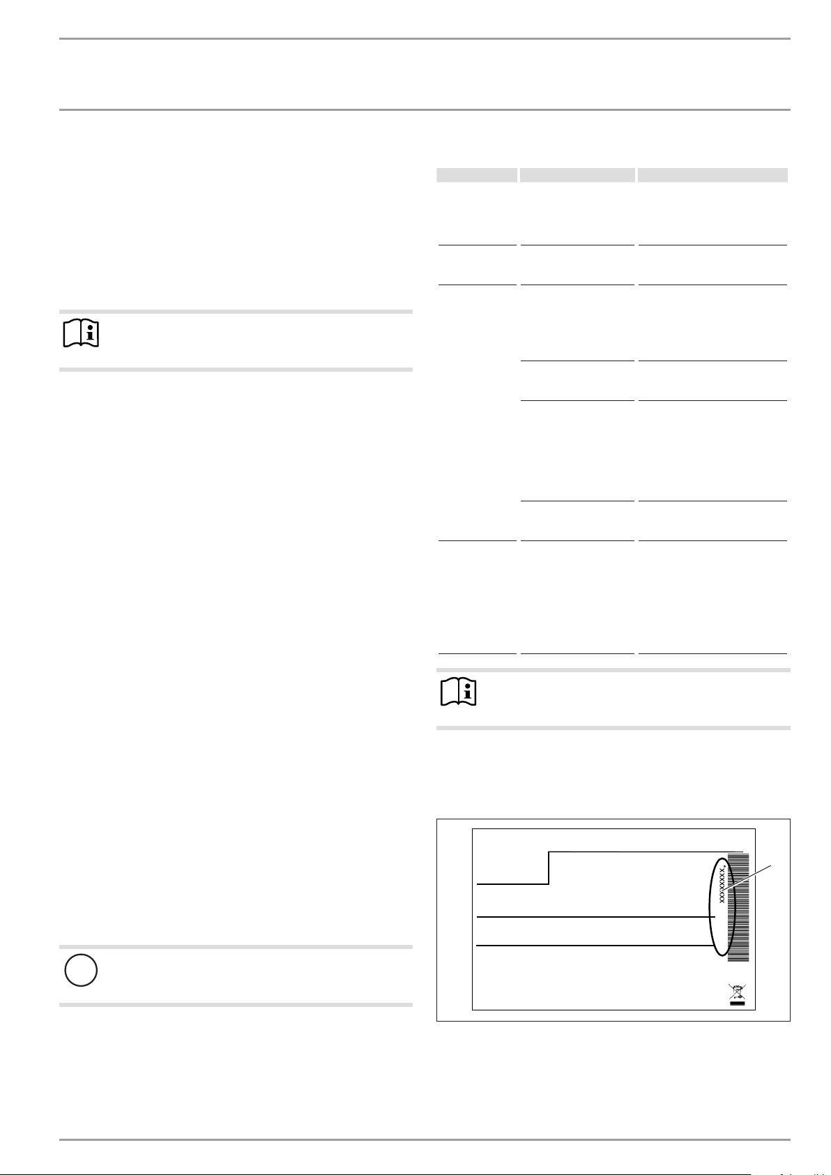
To facilitate and speed up your enquiry, please provide the serial
number from the type plate.
Sample type plate
There is no voltage at the
appliance.
The condensate drain
may be blocked.
The drying out phase of
the building is not yet
complete.
The humidity in the air is
relatively high (≥60%).
The appliance is located
in a moisture-prone
area. Moisture-prone
areas are rooms where
the humidity in the air is
high due to the drying of
laundry, for exam
ple.
The air hoses are incorrectly fitted or sealed.
Cold air escapes.
The heat pump is
drawing heat from the
outdoor air to heat the
building. This can cause
the humidity in the outdoor air to accumulate
as dew or frost on the
cooled heat pump casing.
This is not a defect.
Check the fuses/MCBs in your
fuse box/distribution panel.
If required, reset the MCBs. If
the MCBs trip again after being
reset, notify your contractor.
Clean the condensate drain as
described in chapter ‚Care and
maintenance‘.
If the room is sufficiently well
ventilated or dehumidified,
this condensate should no
longer form on the appliance approx.two years af ter the house
was built.
When the weather conditions
change, condensation should no
longer form on the appliance.
Make sure that the room is
adequately ventilated and dehumidified. If necessary, hang your
laundry up in a different room.
Use a vented tumble dryer.
Please note that condenser
tumble dryers do not reduce the
humidity in the air.
Check whether the air hoses are
correctly fitted and sealed. If
necessary, call your contractor.
Note
Even when the condensate is draining away correctly,
expect water to drip from the appliance onto the floor.
5. Maintenance and care
A damp cloth is sufficient for cleaning all plastic and sheet steel
*xxxxxxxxxxxxxxxxxx*
1
parts. Never use abrasive or corrosive cleaning agents.
Check the condensate drain monthly (visual inspection). Remove
contaminants and blockages immediately.
Damage to the appliance and environment
!
Keep the air discharge and intake apertures free from
snow and leaves.
We recommend an annual inspection (establishing the actual
state) and, if required, maintenance (returning the set state) by a
Montageanweisung beachten! Dichtheit geprüft!
1 Number on the type plate
Made in Germany
qualified contractor.
www.stiebel-eltron.com WPL basic | WPL S basic | 5
26�03�01�1736
INSTALLATION
Safety
INSTALLATION
7. Safety
7.1 General safety instructions
- Only qualified contractors should carry out installation, commissioning, maintenance and repair of the appliance.
- We guarantee trouble-free function and operational reliability only if the original accessories and spare parts intended
for the appliance are used
7.2 Instructions, standards and regulations
Note
Observe all applicable national and regional regulations
and instructions.
8. Appliance description
For external installation the appliance offers additional frost protection of the heating water pipes. The integral frost protection
circuit starts the circulation pump in the heat pump circuit automatically at +8 °C condenser temperature, and thereby ensures
circulation in all water-filled sections. The heat pump is started
automatically no later than when the temperature inside the buffer
cylinder drops below +5 °C.
Air hoses guide the intake air from the outside to the appliance and
route the discharge air from the appliance to the outside. These
are highly flexible, thermally insulated and are self-extinguishing
in case of fire in accordance with ASTMD1692-67T.
8.1 Standard delivery
8.1.1 Standard appliance
- Type plate
- Wiring diagram
8.1.2 Required accessories, external installation
The appliance casing components are supplied in a separate pack.
Description
Accessory for outdoor installation WPL .. Basic
Accessory for outdoor installation WPL 13/18/23 A
8.1.3 Required accessories, internal installation
The appliance casing components are supplied in a separate pack.
Description
Accessory for indoor installation WPL 13/18/23 I
WPIC
WPIC B
8.2 Accessories
8.2.1 Required accessories, internal and external installation
Description
Heat pump manager WPMS 3 or WPMW 3
Remote control for heating systems
Contact sensor
Immersion sensor
8.2.2 Additional required accessories for internal installation
Description
Thermally insulated air hose, 3m or 4m long
Hose connection plate
Wall outlet AWG 560
8.2.3 Further accessories
Description
Buffer cylinder
Pressure hose G 1¼ x 1 m (DN 32)
Pressure hose G 1¼ x 2 m (DN 32)
Pressure hose G 1¼ x 5 m (DN 32)
Pressure hose G 1¼ x 1 m (DN 32), can be trimmed
Hose fittings for pressure hose G 1¼ (DN 32)
Condensate pump
9. Preparations
9.1 Acoustic emissions
On the air intake and air discharge sides, the appliance is louder
than on the enclosed sides. Observe the following information
when selecting the installation location.
Note
For details regarding the sound power level, see chapter
"Specification / Data table".
9.1.1 Sound emissions for external installation
- Lawn areas and shrubs contribute to the reduction of noise.
- Noise propagation can also be reduced through dense palisades or similar.
Ensure that the air intake direction is in line with the main
wind direction. Air should not be drawn in against the wind.
Never direct the air intake or discharge towards noise-sensi-
tive rooms of the house, e.g. bedrooms.
Avoid installation on large, echoing floor areas, e.g. tiled
floors.
Avoid installation between reflective building walls. Reflec-
tive building walls can increase the sound level.
Note
Provide a recess (space) in the substrate to enable water
and electrical pipes/cables to be connected from below.
Also observe the chapter “Installation/Siting”.
6 | WPL basic | WPL S basic www.stiebel-eltron.com
INSTALLATION
Preparations
9.1.2 Sound emissions for internal installation
Never install the appliance directly below or next to living rooms
or bedrooms.
Never install on joists.
Isolate the installation surface. See chapter “Preparing the
installation site for internal installation”.
Connect the heating flow and return using flexible pres-
sure hoses. Suitable pressure hoses can be found in chapter
“Accessories”.
Insulate all pipe fixings and wall outlets against structure-
borne noise transmission.
Never direct the air intake and discharge apertures in exter-
nal walls towards neighbouring windows or living rooms/
bedrooms.
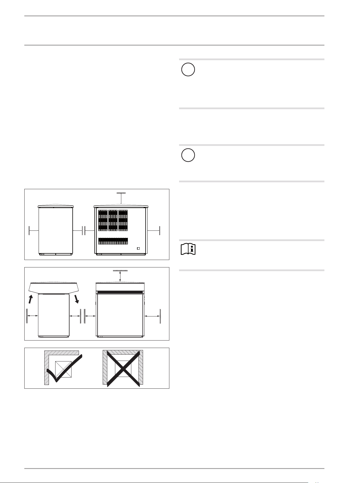
9.2 Minimum clearances
9.2.1 External installation
≥700
≥500 ≥500≥500
≥1000
Damage to the appliance and environment
!
Please note that the outdoor air must be able to flow
unimpeded into the appliance, and the exhaust air must
be able to be expelled without obstruction.
If the air intake and discharge of the appliance are obstructed by surrounding objects, this may cause a thermal
short-circuit.
Ensure that the appliance is not surrounded by any objects
such as buildings, walls or fences.
If necessary, maintain a greater clearance to the surrounding
objects.
Damage to the appliance and environment
!
The air flow rate through the appliance must not fall
below the minimum level. If the air flow rate falls below
the minimum level, trouble-free operation of the appliance is not guaranteed.
Ensure that the minimum air flow rate is maintained. Ob-
serve the details in chapter “Specification / Data table”.
If necessary, maintain a greater clearance to the surrounding
objects.
If the air discharge side of the appliance faces a wall of the house,
condensate may form on this wall from the cool air at the air
discharge.
≥700
≥500
≥500
Do not install the appliance in a recess. Two sides of the ap-
pliance must remain exposed.
Maintain the minimum clearances to ensure trouble-free op-
eration of the appliance and facilitate maintenance work.
In order to prevent air “short circuits”, maintain the mini-
mum clearances in the case of surrounding structures and
in particular in the case of cascades. Maintain the flow rate
on the heat source side (see chapter “Specification / data
table“).
≥500
≥1000
Note
D0000019239
D0000019241
91�00�00�0036
If the air discharge side faces house walls, maintain a
minimum clearance of 2m between the appliance and
the building.
www.stiebel-eltron.com WPL basic | WPL S basic | 7
INSTALLATION
3
Preparations
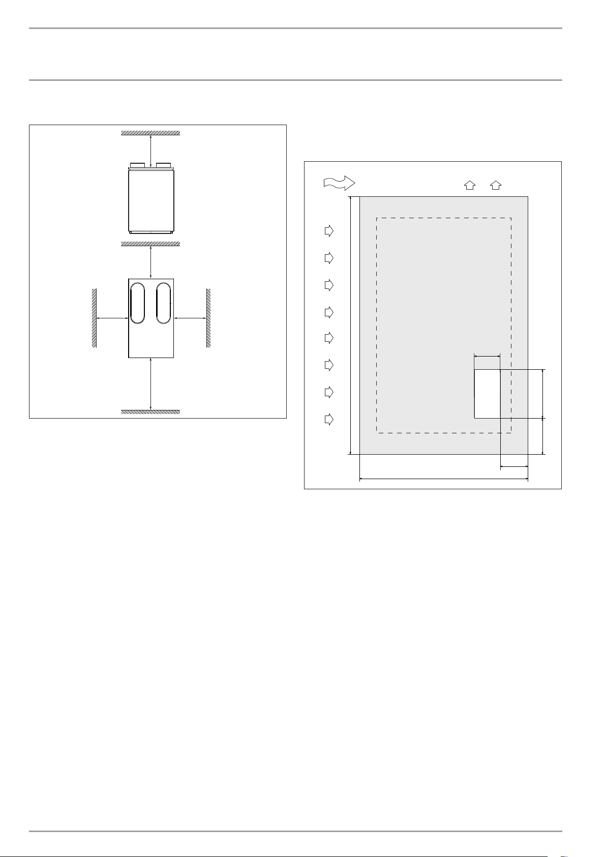
9.2.2 Internal installation
≥500
≥500
≥500
≥1000
≥500
9.3.2 Preparing the installation site for external installation
Observe chapter “Sound emissions for external installation”.
Example: Foundations with recess
2
1
1440
150
4
D0000019242
300
Maintain the minimum clearances to ensure trouble-free op-
eration of the appliance and facilitate maintenance work.
9.3 Preparing the installation site
9.3.1 General information
Ensure that the appliance is accessible from all sides.
- The substrate must be horizontal, level, solid and permanent.
Observe the minimum clearances in chapter “Preparations/
Minimum clearances”.
Ensure the entire heat pump frame is in contact with the sub-
strate. Uneven substrates can increase sound emissions.
190
170
1000
D0000019240
1 Air intake
2 Air discharge
3 Main wind direction
4 Recess
8 | WPL basic | WPL S basic www.stiebel-eltron.com
INSTALLATION
6
Preparations
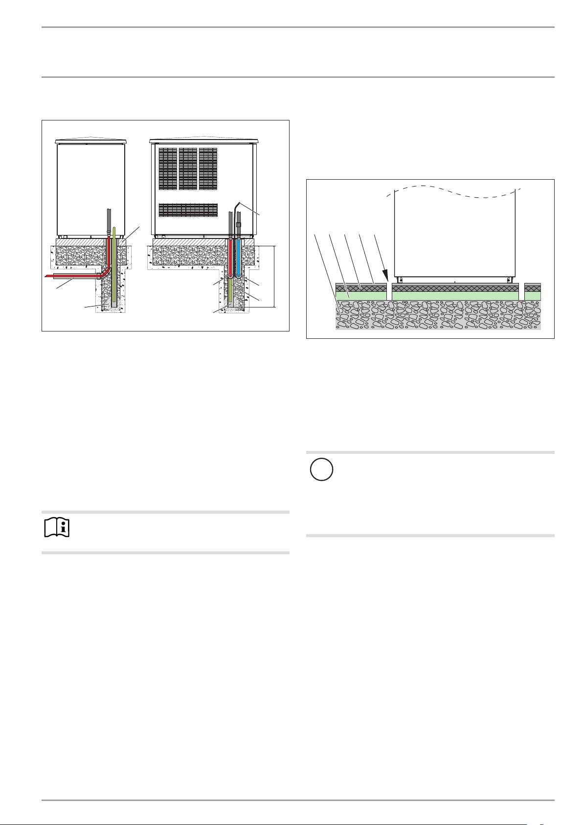
Example: Routing pipes underground
8
4
3
5
A Frost level
1 Heating circuit flow
2 Heating circuit return
3 Conduit for supply lines
4 Foundation
5 Gravel bed
6 Drainage pipe
7 Condensate hose
8 Electrical cables/leads
Use only cables suitable for outdoor use.
Protect the flow and return pipes against frost with sufficient
thermal insulation. Provide thermal insulation in accordance
with applicable regulations.
Protect all supply lines against humidity, damage and UV ra-
diation by means of a conduit.
Note
When routing the condensate hose, observe the chapter
“Installation / condensate drain”.
1
2
7
9.3.3 Preparing the installation site for internal installation
Observe chapter “Sound emissions for internal installation”.
Isolate the mounting surface around the heat pump by re-
cesses. After completing the installation, seal these recesses
with a water-impervious and sound insulating material, such
as silicone for example.
1 2 3 54
A
D0000019238
1 Concrete base
2 Impact sound insulation
3 Floating screed
4 Floor covering
5 Recess
In chapter “Specification/Connections and dimensions, internal
installation”, the location and dimensions of the air intake and
discharge apertures as well as those of the outlets/entries for
water pipes and cables in the appliance cover can be seen.
Material losses
!
The floor of the installation room must be water resistant.
During appliance operation, the outdoor air releases up
to 50l of condensate per day. If the condensate drain is
not installed correctly or if maintenance is not carried out
properly, water may escape. We recommend installing a
drain in the floor of the installation room.
26�03�01�1466
www.stiebel-eltron.com WPL basic | WPL S basic | 9
INSTALLATION
Mounting
9.4 Electrical installation
DANGER Electrocution!
Carry out all electrical connection and installation work
in accordance with national and regional regulations.
DANGER Electrocution!
Only use a permanent connection to the power supply.
The appliance must be able to be separated from the
power supply by an isolator that disconnects all poles
with at least 3mm contact separation. This requirement
can be met by contactors, isolators, fuses etc.
Note
The specified voltage must match the mains voltage. Observe the type plate.
Route cables with the following cross-sections in accordance with
the respective fuse rating:
Fuse rating Cable cross-section
C 16 A
C 25 A 6.0 mm² for routing through a wall
C 35 A 6.0 mm² for routing multi-core cables on a wall or in an
The electrical specifications are given in the “Data table”. The BUS
cable requires a cable J-Y (St) 2x2x0.8mm².
2.5 mm²
1.5 mm² with only two live cores and routing on a wall or in
an electrical conduit on a wall
4.0 mm² for routing multi-core cables on a wall or in an
electrical conduit on a wall
electrical conduit on a wall
10.2 Positioning
10.2.1 General information
Undo the fixing screws on the appliance frame and keep
them safe. Two or four screws are provided in the frame
to secure the cover. One screw respectively is provided to
secure the side panels (see also chapter “Fitting the casing
components”).
Note
Fit the casing components only after the electrical and
hydraulic connections have been made.
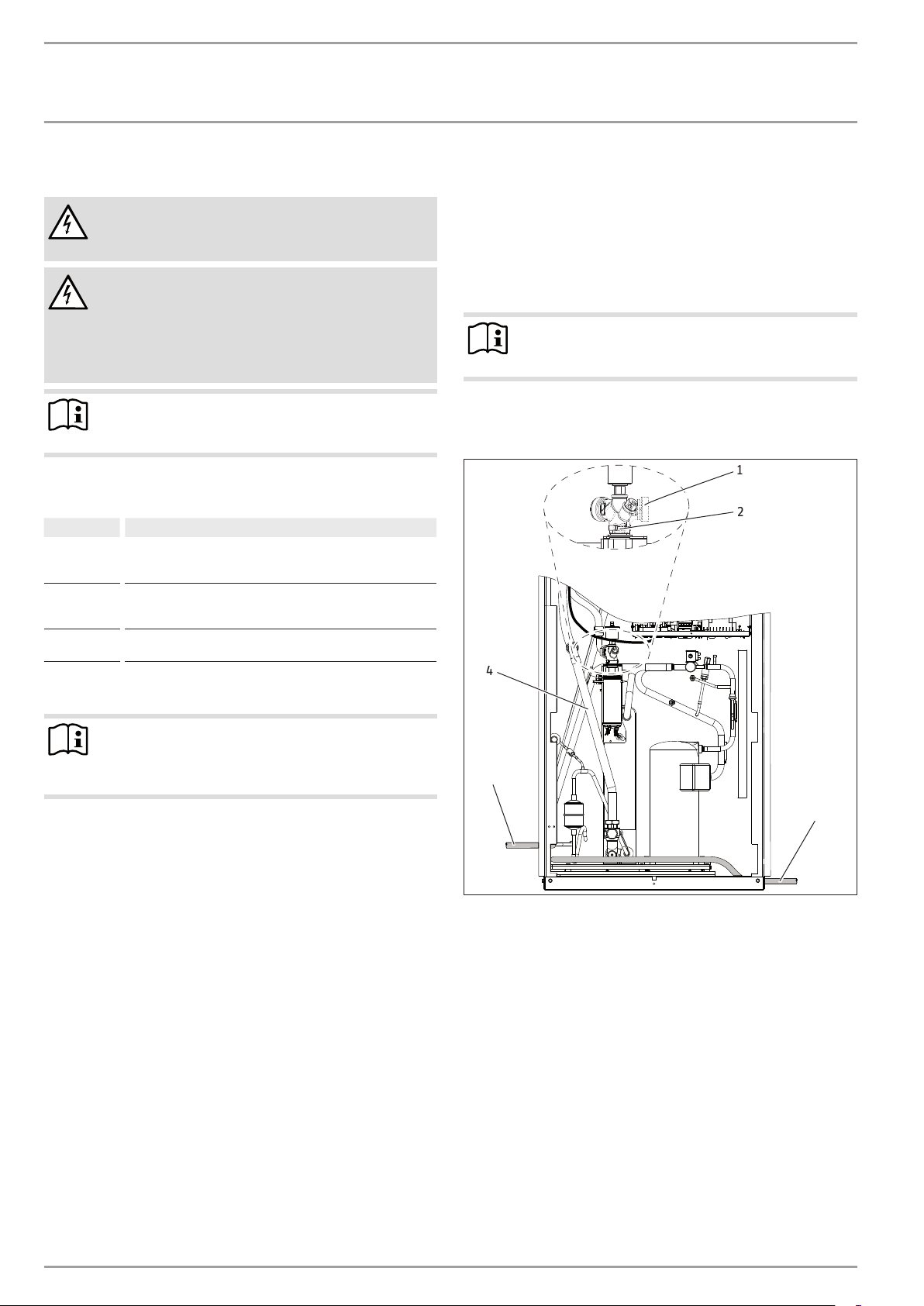
10.2.2 Internal installation
Position the standard appliance on the prepared substrate.
1
2
4
Note
Provide separate fuses/MCBs for the 3 power circuits of
the appliance, the control unit and the electric booster
heater.
9.5 Buffer cylinder
A buffer cylinder is recommended to ensure trouble-free appliance
operation. The buffer cylinder not only provides hydraulic separation of the volume flow in the heat pump and heating circuit, but
also serves as an energy source for defrosting the evaporator.
10. Mounting
10.1 Handling
Pay attention to the appliance’s centre of mass when trans-
porting the appliance.
The centre of mass is located in the compressor area.
- Lifting slings for transporting the standard appliance can be
hooked in anywhere on the lower frame.
Protect the appliance against heavy impact during transport.
- Only allow the appliance to be tilted during transport for a
short time to one of its longitudinal sides.
The longer the appliance is tilted, the greater the distribution
of refrigerant oil in the system. Wait approx. 30 minutes before starting the appliance after it has been tilted.
3
3
26�03�01�1650�
1 Connector
2 Union nut
3 Pipe bend, heating circuit return
4 Condensate drain hose
Undo the union nut from the heating flow.
Rotate the connector approx. 145°.
Retighten the union nut.
Fit the pipe bend for the heating circuit return (part of the
“Internal installation accessories”).
Route the condensate hose out of the appliance, either on the
r.h. or the l.h. side.
10 | WPL basic | WPL S basic www.stiebel-eltron.com
INSTALLATION
Mounting
1
5
2
6
3
4
1 Appliance power cable
2 Electric booster heater power cable
3 Control cable
4 BUS cable
5 Heating flow
6 Heating return
Position the cover on the appliance, and secure it with two
screws.
Cut the pipe outlets for the water pipes out of the cover.
Route the water pipes through the cover into the appliance.
Then route the cables from above through the cable entries
with strain relief fittings (PG fittings) into the appliance.
The open PG fittings are intended for the following: Appliance power supply, control cable and BUS cable.
10.2.3 External installation
Observe the air discharge direction.
Position the standard appliance on the prepared substrate.
Material losses
!
Rodents may get into the appliance through the knockout aperture.
Close off the knock-out aperture.
10.3 Heating water connection
The heating system to which the heat pump is to be connected
must be installed by a qualified contractor in accordance with the
26�03�01�0170
water installation drawings that are part of the technical documents.
Thoroughly flush the pipework before connecting the heat
pump. Debris, such as rust, sand and sealant, can impair the
operational reliability of the heat pump.
Connect the heat pump on the heating water side. Check for
tightness.
Connect flexible pressure hoses to the connectors; these will
act as anti-vibration dampers.
The pressure hoses should be at least 1 m long.
10.3.1 Oxygen diffusion
Material losses
!
Avoid open heating systems and plastic pipes in underfloor heating systems which are permeable to oxygen.
In underfloor heating systems with plastic pipes that are permeable to oxygen and in open vented heating systems, oxygen
diffusion may lead to corrosion on the steel components of the
heating system (e.g. on the indirect coil of the DHW cylinder, on
buffer cylinders, steel heating elements or steel pipes).
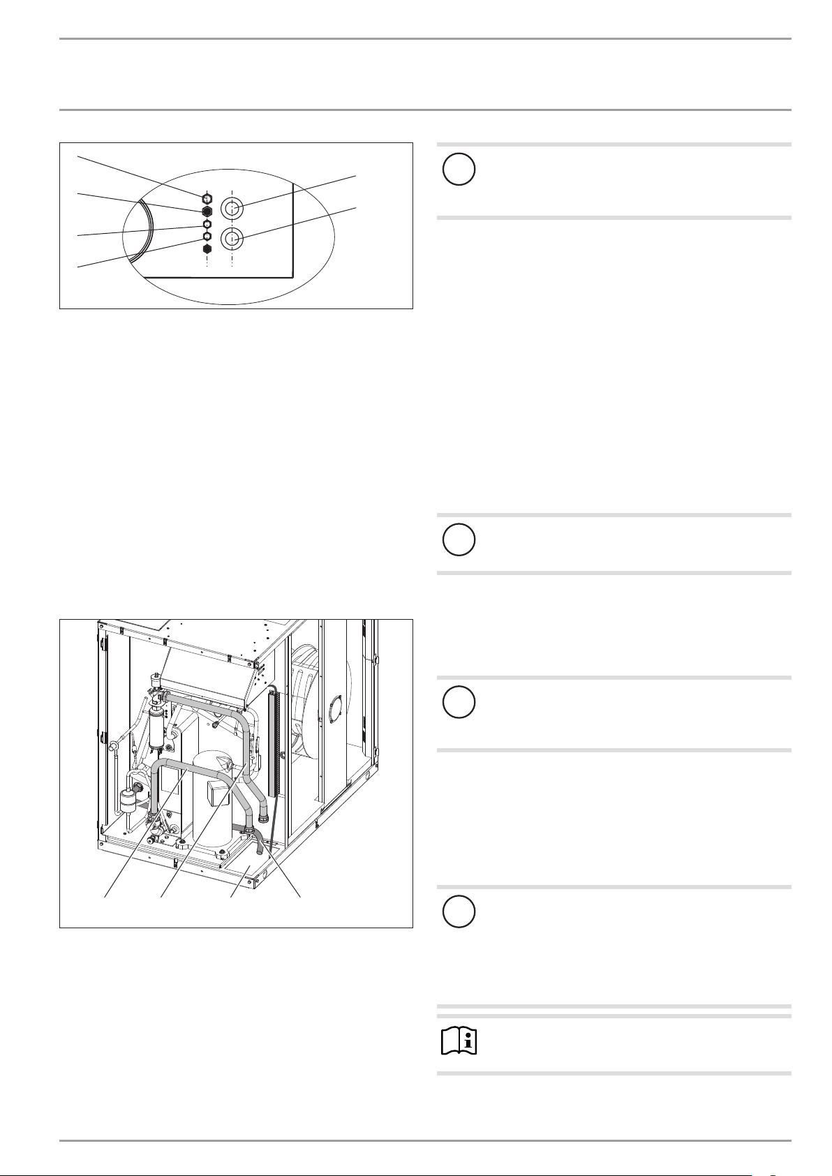
234
1 Condensate hose
2 Supply line outlet
3 Pipe bend, heating circuit flow
4 Pipe bend, heating circuit return
Fit the pipe bends for the heating circuit flow and return
(part of the “External installation accessories”).
Route the water pipes and the cables from below through the
cut-out in the floor into the appliance.
1
Material losses
!
The products of corrosion (e.g. rusty sludge) can settle in
the heating system components and can result in a lower
output or fault shutdowns due to reduced cross-sections.
10.3.2 Filling the heating system
Water quality
A fill water analysis must be available prior to charging the system. This may, for example, be requested from the relevant water
supply utility.
Material losses
26�03�01�1644�
!
To avoid damage as a result of scaling, it may be necessary to soften or desalinate the fill water. The fill water
limits specified in chapter "Specification / Data table"
must always be observed.
Recheck these limits 8-12 weeks after commission-
ing and as part of annual system maintenance.
Note
With conductivity of >1000μS/cm, desalination treatment
is recommended in order to avoid corrosion.
www.stiebel-eltron.com WPL basic | WPL S basic | 11