

OPERATION AND INSTALLAT ION
Compact air source heat pump
» WPL 10 I
» WPL 10 IK 3

2 | WPL 10 www.stiebel-eltron.com
CONTENTS
SPECIAL INFORMATION
OPERATION
1. General information �����������������������������������������3
1.1 Relevant documents_____________________________________________ 3
1.2 Safety instructions _______________________________________________ 3
1.3 Other symbols in this documentation _______________________ 4
1.4 Units of measurement __________________________________________ 4
1.5 Standardised output data ______________________________________ 4
2. Safety ���������������������������������������������������������� 4
2.1 Intended use ______________________________________________________ 4
2.2 General safety instructions ____________________________________ 4
2.3 Test symbols ______________________________________________________ 4
3. Appliance description ���������������������������������������4
3.1 Properties _________________________________________________________ 4
3.2 Function ___________________________________________________________ 5
4. Settings ������������������������������������������������������� 5
5. Maintenance and care ���������������������������������������5
6. Troubleshooting ����������������������������������������������5
INSTALLATION
7. Safety ���������������������������������������������������������� 6
7.1 General safety instructions ____________________________________ 6
7.2 Instructions, standards and regulations ____________________ 6
8. Appliance description ���������������������������������������6
8.1 Standard delivery ________________________________________________ 6
8.2 Accessories ________________________________________________________ 6
8.3 Details on energy consumption _______________________________ 6
9. Preparations �������������������������������������������������� 7
9.1 Electrical installation____________________________________________ 8
10. Installation ����������������������������������������������������8
10.1 Transport __________________________________________________________ 8
10.2 Siting _______________________________________________________________ 8
10.3 Heating water connection ______________________________________ 8
10.4 Oxygen diffusion _________________________________________________ 9
10.5 Filling the heating system _____________________________________ 9
10.6 Venting the heating system ____________________________________ 9
10.7 Safety temperature controller for underfloor heating
system _____________________________________________________________ 9
10.8 Buffer cylinders __________________________________________________ 9
10.9 Flow rate, heating side ________________________________________ 10
10.10 Condensate drain _______________________________________________ 11
10.11 Second heat generator ________________________________________ 11
10.12 Removing the casing parts ___________________________________ 11
11. Power supply ����������������������������������������������� 12
11.1 General ___________________________________________________________ 12
11.2 Electrical connection WPL10I _______________________________ 12
11.3 Electrical connection WPL10IK3 ___________________________ 12
11.4 Connecting compressor and electric emergency/
booster heater ___________________________________________________ 13
11.5 Control voltage connection ___________________________________ 14
11.6 Low voltage connection _______________________________________ 14
12. Fitting casing components �������������������������������� 14
13. Fitting air hoses �������������������������������������������� 15
13.1 WPL 10 I ___________________________________________________________ 15
13.2 WPL 10 IK 3 _______________________________________________________16
14. Commissioning ��������������������������������������������� 16
14.1 Checks before commissioning the heat pump manager 16
14.2 Commissioning the heat pump manager __________________ 16
14.3 Initial start-up ___________________________________________________ 16
15. Shutdown ��������������������������������������������������� 17
15.1 Standby mode ___________________________________________________ 17
15.2 Power interruption _____________________________________________ 17
16. Appliance handover ���������������������������������������� 17
17. Troubleshooting �������������������������������������������� 18
17.1 Controls on the IWS ____________________________________________ 18
17.2 Fan noise _________________________________________________________ 18
18. Maintenance ������������������������������������������������ 18
19. Specification ������������������������������������������������ 19
19.1 Dimensions and connections WPL10I _____________________ 19
19.2 Dimensions and connections WPL10IK3 _________________ 20
19.3 Wiring diagram WPL10I ______________________________________ 21
19.4 Wiring diagram WPL10IK3 __________________________________ 22
19.5 Output diagrams WPL10I | WPL10IK3 ___________________ 23
19.6 Data table ________________________________________________________ 24
GUARANTEE
ENVIRONMENT AND RECYCLING
www.stiebel-eltron.com WPL 10 | 3
SPECIAL INFORMATION | OPERATION
General information
SPECIAL INFORMATION
- The appliance may be used by children aged8
and up and persons with reduced physical, sensory or mental capabilities or a lack of experience
and know-how, provided that they are supervised
or they have been instructed on how to use the
appliance safely and have understood the resulting risks. Children must never play with the appliance. Children must never clean the appliance
or perform user maintenance unless they are
supervised.
- The connection to the power supply must be in
the form of a permanent connection. Ensure the
appliance can be separated from the power supply by an isolator that disconnects all poles with
at least 3mm contact separation.
- Maintain the minimum clearances to ensure trouble-free operation of the appliance and facilitate
maintenance work.
- Never interrupt the heat pump power supply,
even outside the heating season. Otherwise, system frost protection is not guaranteed.
- The heat pump manager automatically switches
the heat pump to summer or winter mode.
- If the heat pump and frost protection are completely switched off, drain the system on the
water side.
OPERATION
1. General information
The chapters "Special Information" and "Operation" are intended
for both the user and qualified contractors.
The chapter "Installation" is intended for qualified contractors.
Note
Read these instructions carefully before using the appliance and retain them for future reference.
Pass on the instructions to any new user where appropriate.
1.1 Relevant documents
Operating and installation instructions for the WPM heat
pump manager
Operating and installation instructions of all other com-
ponents in the system
1.2 Safety instructions
1.2.1 Structure of safety instructions
!
KEYWORD Type of risk
Here, possible consequences are listed that may result
from failure to observe the safety instructions.
Steps to prevent the risk are listed.
1.2.2 Symbols, type of risk
Symbol Type of risk
Injury
Electrocution
1.2.3 Keywords
KEYWORD Meaning
DANGER Failure to observe this information will result in serious
injury or death.
WARNING Failure to observe this information may result in serious
injury or death.
CAUTION Failure to observe this information may result in non-seri-
ous or minor injury.
!
OPERATION
Safety
4 | WPL 10 www.stiebel-eltron.com
1.3 Other symbols in this documentation
Note
General information is identified by the adjacent symbol.
Read these texts carefully.
Symbol Meaning
Material losses
(appliance damage, consequential losses and environmental pollution)
Appliance disposal
This symbol indicates that you have to do something. The ac-
tion you need to take is described step by step.
1.4 Units of measurement
Note
All measurements are given in mm unless stated otherwise.
1.5 Standardised output data
Explanations to determine and interpret the specified standardised
output data.
1.5.1 Standard: EN 14511
The output data specifically mentioned in text, diagrams and
technical datasheets has been calculated according to the test
conditions of the standard shown in the heading of this section.
Generally, these standardised test conditions will not fully meet
the conditions found at the installation site of the system user.
Depending on the chosen test method and the extent to which
this method deviates from the conditions defined in the norm
shown in the heading of this section, any deviations can have a
considerable impact.
Further factors that have an influence on the test values are the
measuring equipment, the system configuration, the age of the
system and the flow rates.
A confirmation of the specified output data can only be obtained
if the test conducted for this purpose is also performed in accordance with the conditions defined in the norm shown in the
heading of this section.
2. Safety
2.1 Intended use
This appliance is intended for domestic use. It can be used safely
by untrained persons. The appliance can also be used in a non-domestic environment, e.g. in a small business, as long as it is used
in the same way.
Any other use beyond that described shall be deemed inappropriate. Observation of these instructions and of instructions for any
accessories used is also part of the correct use of this appliance.
2.2 General safety instructions
!
WARNING Injury
The appliance may be used by children aged 8 and older
and persons with reduced physical, sensory or mental
capabilities or a lack of experience and know-how, provided that they are supervised or they have been instructed on how to use the appliance safely and have
understood the resulting risks. Children must never play
with the appliance. Children must never clean the appliance or perform user maintenance unless they are
supervised.
2.3 Test symbols
See type plate on the appliance.
3. Appliance description
3.1 Properties
The appliance is an air source heat pump designed for
use as a heating heat pump. The appliance extracts heat
from the outdoor air at a low temperature level and transfers it to the heating water at a higher temperature level.
The heating water can be heated up to a flow temperature of 60 °C.
The appliance is equipped with an electric emergency/booster
heater (DHC). If the dual mode point is undershot in mono mode
operation, the electric emergency/booster heater is activated to
safeguard heating operation and the provision of high DHW temperatures. In such a case in mono energetic operation, the electric
emergency/booster heater is activated as a booster heater.
This appliance has further operational characteristics:
- Suitable for underfloor and radiator heating.
- Preferred for low temperature heating systems.
- Extracts heat from the outdoor air even at outside temperatures of -20 °C.
- Corrosion-protected, external casing made from hot-dipped
galvanised sheet steel plus stove-enamelled finish.
- Comprises all components and safety equipment required for
operation.
- Filled with non-combustible safety refrigerant.
Note
For centralised control of the heating system, you would
need the WPM heat pump manager.
!
OPERATION
Settings
www.stiebel-eltron.com WPL 10 | 5
3.2 Function
Heat is extracted from the outdoor air via the heat exchanger
(evaporator) on the air side. The refrigerant evaporates and is
compressed by a compressor. This process requires electrical
energy.
The refrigerant is then at a higher temperature level and transfers
the heat drawn from the air to the heating system via an additional
heat exchanger (condenser). During this process, the refrigerant
expands and the cycle begins again.
At air temperatures below approx. 7°C, the humidity in the air
condenses as hoarfrost on the evaporator fins. Any hoarfrost is automatically defrosted. Water created from this defrosting process
collects in the defrost pan and is drained off via a hose.
In the defrost cycle, the fan is switched OFF and the heat pump
circuit is reversed. The heat required for defrosting is drawn from
the buffer cylinder or heating circuit. The heat pump automatically
reverts to heating mode at the end of the defrost cycle.
Special features of the WPL10IK3
The WPL10IK3 is equipped as standard with the WPM heat pump
manager. It is also equipped with a heating circuit pump, an expansion
vessel and a three-way valve for changeover between the heating circuit
and DHW heating. The standard delivery also includes the air hoses and
their fixing materials.
4. Settings
The system is operated exclusively with the WPM heat pump manager.
Please observe the heat pump manager operating and instal-
lation instructions.
5. Maintenance and care
!
Damage to the appliance and environment pollution
Maintenance work, such as checking the electrical safety,
must only be carried out by a qualified contractor.
Protect the appliance from dust and dirt ingress dur-
ing building work.
A damp cloth is sufficient for cleaning all plastic and sheet metal
parts. Never use abrasive or corrosive cleaning agents.
Every month, check that the condensate drain is working
correctly (visual inspection). When doing so, check whether
water is collecting below or next to the appliance. Observe
the "Troubleshooting" chapter.
We recommend an annual inspection (to establish the current
condition of the system), and service by a contractor if required
(to return the system into its original condition).
6. Troubleshooting
Fault Cause
Remedy
There is no hot
water or the
heating system
stays cold.
No power at the appliance.
Check the fuses/ MCBs in your
fuse box/distribution panel.
If required, reset the MCBs. If
the MCBs trip again after being
reset, notify your contractor.
Water is leaking
from the appliance.
The condensate drain
may be blocked.
Call your contractor to have the
condensate drain cleaned out.
Condensate is
collecting on the
outside of the
appliance or the
air hoses.
The drying out phase of
the building is not yet
complete.
If the room is sufficiently well
ventilated and dehumidified,
this condensate should no
longer form on the appliance approx.two years af ter the house
was built.
The relative humidity in
the air is high (≥60%).
A change in weather conditions
should no longer cause condensation to form on the appliance.
The appliance is sited
in a damp room. Damp
rooms are those where
humidity in the air is high
due to the drying of laundry, for example.
Ensure that the room is adequately ventilated and dehumidified. If necessary, hang your
laundry in a different room.
Use a vented tumble dryer.
Please note that condenser
tumble dryers do not reduce the
humidity in the air.
The air hoses are incorrectly fitted or poorly
sealed.
Cold air escapes.
Check whether the air hoses
are correctly fitted and sealed.
If necessary, refer to your contractor.
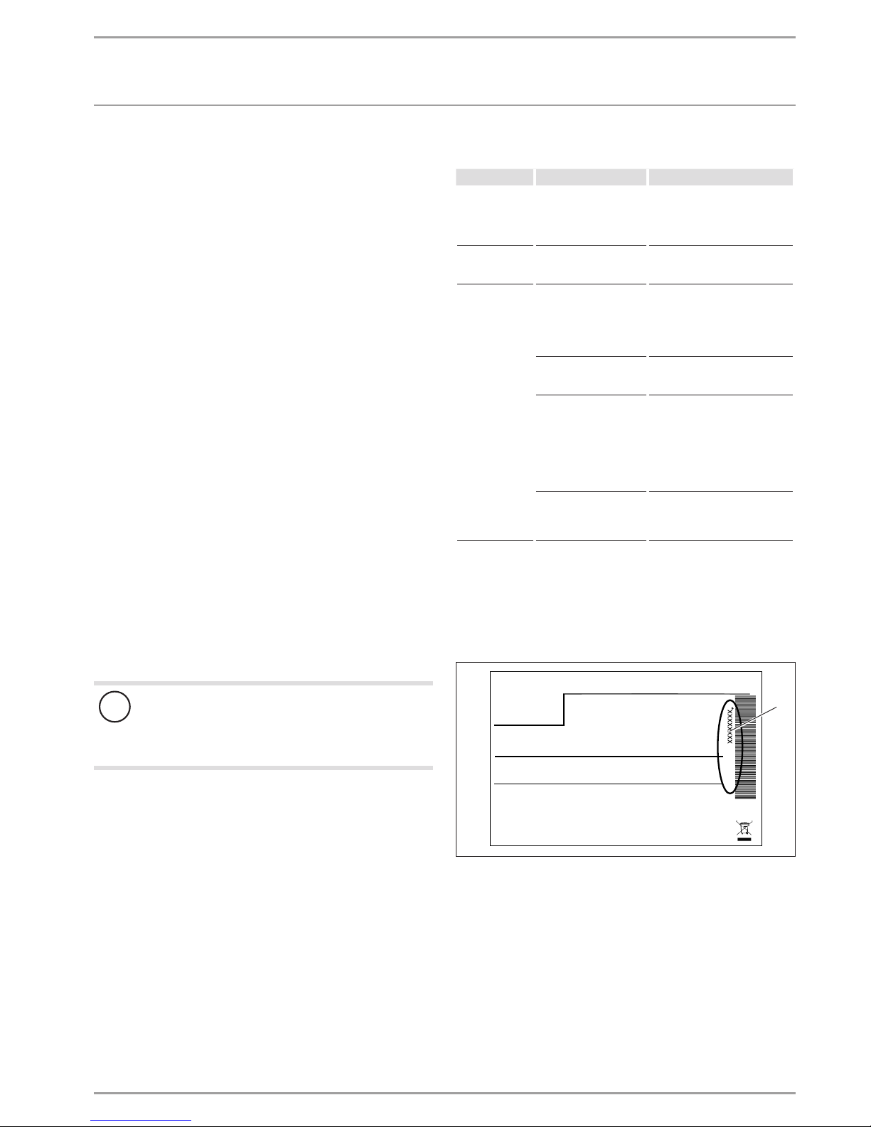
If you cannot remedy the fault, notify your contractor. To facilitate
and speed up your enquiry, please provide the serial number from
the type plate. The type plate is located at the front top, on the
right or left hand side of the casing.
Sample type plate
Montageanweisung beachten! Dichtheit geprüft!
Made in Germany
*xxxxxxxxxxxxxxxxxx*
26_03_01_1736
1
1 Number on the type plate
6 | WPL 10 www.stiebel-eltron.com
INSTALLATION
Safety
INSTALLATION
7. Safety
Only a qualified contractor should carry out installation, commissioning, maintenance and repair of the appliance.
7.1 General safety instructions
We guarantee the trouble-free function and operational reliability only if original accessories and spare parts intended for the
appliance are used.
7.2 Instructions, standards and regulations
Note
Observe all applicable national and regional regulations
and instructions.
8. Appliance description
For outdoor installation the appliance offers additional frost protection of the heating water pipes. The integral frost protection
circuit starts the heating circuit pump in the heat pump circuit
automatically at +8°C condenser temperature, and thereby ensures circulation in all water-filled sections.
The heat pump starts automatically when the temperature in the
heat pump circuit drops below +5°C.
8.1 Standard delivery
8.1.1 WPL 10 I
The following are delivered with the appliance:
- Wiring diagram
8.1.2 WPL 10 IK 3
The following are delivered with the appliance:
- 2 x air hose with fixing materials
- Wiring diagram
8.2 Accessories
Designation
Heat pump manager in wall mounted enclosure, WPMW (WPL10I only)
Pressure hoses SD25 or SD32
Wall duct with external wall grille AWG315SR
Wall duct with external wall grille AWG315GL
Thermally insulated air hose, 4m (WPL10I only)
Hose connection panel
Condensate pump PK10
Cylinder SBP200E
Cylinder SBP400E
Cylinder SBP700E
Heat pump manager in wall mounted enclosure, WPMW (WPL10I only)
Heat pump manager as control panel mounted version, WPMS (WPL10I only)
Mixer module with wall mounting enclosure, MSMW
Designation
Mixer module as control panel mounted version, MSMS
Pressure hose G 1¼” x 1m
Pressure hose G 1¼” x 2 m
Pressure hose G 1¼” x 5 m
Pressure hose G 1¼” x 10 m
Heat pump compact installation WPKI 5
UP kit 25 / 7E (for WPKI5)
Remote control for heating systems FE 7
Contact sensor AVF 6
Immersion sensor TF 6
STB-FB safety temperature controller for underfloor heating
Filter assembly 22 mm (FS-WP 22)
Filter assembly 28 mm (FS-WP 28)
www.stiebel-eltron.com WPL 10 | 7
INSTALLATION
Preparations
9. Preparations
Note
The appliance is designed for internal installation, except
in damp areas.
- Never install on joists.
Never install the appliance directly below or next to living
rooms or bedrooms.
Never direct the air intake and discharge apertures in exter-
nal walls towards neighbouring windows or living rooms/
bedrooms.
Protect pipe transitions through walls and ceilings with an-
ti-vibration insulation.
Note
For details regarding the sound power level, see chapter
"Specification / Data table".
The room in which the appliance is to be installed must meet the
following conditions:
- Free from the risk of frost.
- The room must not be subject to a risk of explosions arising
from dust, gases or vapours.
- When installing the appliance in a boiler room together with
other heating equipment, ensure that the operation of other
heating equipment will not be impaired.
- Minimum volume of the installation room. The minimum
volume of the installation room is assured if the minimum
clearances are observed.
- Load-bearing floor (for the weight of the appliance, see
chapter "Specification / Data table").
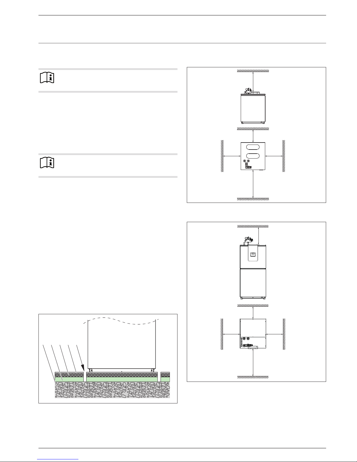
For installation on floating screeds, make provisions for a
quiet heat pump operation.
Isolate the mounting surface around the heat pump by a re-
cess. After completing the installation, seal the recess with
a water-impervious and sound insulating material, such as
silicone for example.
1 2 3 54
26_03_01_1466
1 Concrete base
2 Impact sound insulation
3 Floating screed
4 Floor covering
5 Recess
Minimum clearances WPL10I
≥500
≥200
≥600
≥500
≥1000
D0000019289
Minimum clearances WPL10IK3
≥500
≥200
≥500
≥500
≥1000
D0000019298
Maintain the minimum clearances to ensure trouble-free op-
eration of the appliance and facilitate maintenance work.
8 | WPL 10 www.stiebel-eltron.com
INSTALLATION
Installation
9.1 Electrical installation
DANGER Electrocution
Carry out all electrical connection and installation work
in accordance with national and regional regulations.
DANGER Electrocution
The connection to the power supply must be in the form
of a permanent connection. Ensure the appliance can
be separated from the power supply by an isolator that
disconnects all poles with at least 3mm contact separation. This requirement can be met with contactors, circuit
breakers, fuses/MCBs, etc.
Note
The specified voltage must match the mains voltage. Observe the type plate.
Install cables with the following cross-sections in accordance with
the respective fuse rating:
MCB/fuse
rating
Assignment Cable cross-section
C 16 A Compressor 2.5 mm²
B 16 A
Electric emergency/
booster heater (BH)
2.5 mm²
1.5 mm² with only two live cores and
routing on a wall or in an electrical conduit on a wall.
B 16 A Control cable 1.5 mm²
The electrical data is provided in the "Specification" chapter. For
the WPL10I, you require a J-Y (St) 2x2x0.8mm² electric BUS cable.
!
Material losses
Provide separate fuses/MCBs for the two power circuits,
i.e. for the compressor and the electricemergency/booster heater circuits.
10. Installation
10.1 Transport
Pay attention to the appliance's centre of gravity when trans-
porting the appliance.
- The centre of gravity is in the area where the compressor is
located.
- With the WPL10IK3, ensure that the control fascia is at the
top during transport.
- Lifting slings for handling the standard appliance can be
hooked in anywhere on the bottom of the frame.
Protect the appliance against heavy impact during transport.
- If the appliance needs to be tilted during transport only do so
for a short time on one of its longitudinal sides.
- The longer the appliance is tilted, the greater the distribution
of refrigerant oil in the system.
Wait approximately 30minutes before starting the appliance
after it has been tilted.
10.2 Siting
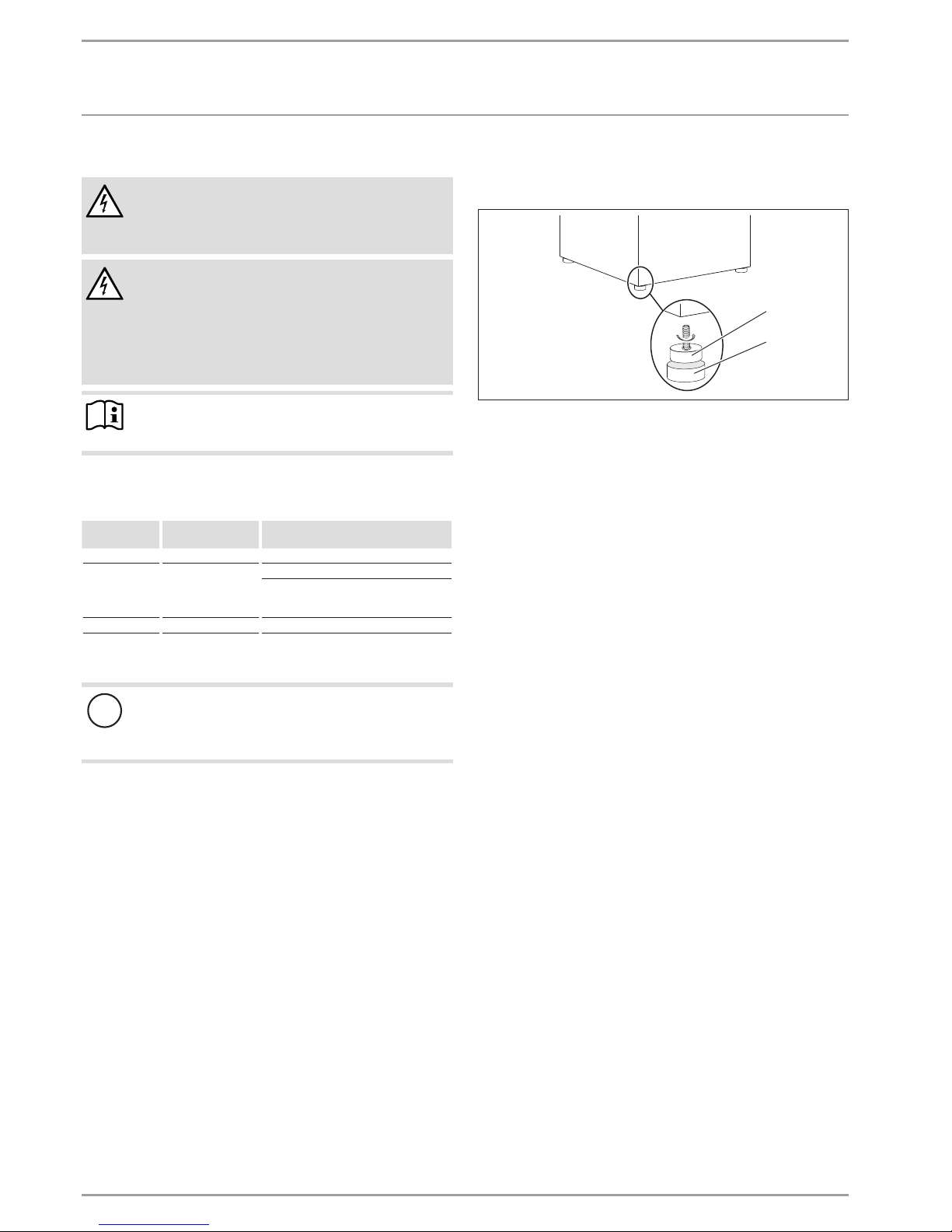
Remove the packaging film and the top and side EPS
padding.
D0000051813
1
2
1 Appliance foot
2 Sliding block
Undo the four fixing screws underneath the pallet.
Remove the appliance feet from the pack. Fully turn the feet
onto the appliance, without removing the appliance from the
pallet.
Take the appliance off the pallet and set it down on the pre-
pared base. If required, use the sliding blocks provided to
help you position the appliance.
Observe minimum distances (see the "Preparations / Mini-
mum clearances" chapter).
Level the appliance horizontally by adjusting the feet.
10.3 Heating water connection
The heating system to which the heat pump is connected must be
installed by a qualified contractor in accordance with the water
installation diagrams that are part of the technical guides.
In dual mode operation, return water from the second heat generator may flow through the heat pump. The return water temperature must not exceed 60°C.
Thoroughly flush the pipework before connecting the heat
pump. Foreign bodies, such as rust, sand and sealant, can
impair the operational reliability of the heat pump. We recommend installing our filter assembly in the heating return
(see chapter "Accessories").
On the WPL10I, connect one flexible pressure hose each to
the heating flow and heating return connections to act as
an anti-vibration mount. The pressure hoses are part of the
standard delivery. Anti-vibration mounts are already fitted to
the WPL10IK3.
Ensure the correct connection of the heating flow and return.
Check for tightness.
When sizing the heating circuit, observe the maximum avail-
able external pressure differential (see the "Specification /
Data table" chapter).
Provide thermal insulation in accordance with applicable
regulations.
www.stiebel-eltron.com WPL 10 | 9
INSTALLATION
Installation
10.4 Oxygen diffusion
!
Material losses
Avoid using open vented heating systems or steel pipework in conjunction with underfloor heating systems with
plastic pipes that are permeable to oxygen.
In open vented heating systems or in underfloor heating systems
with permeable plastic pipes, oxygen diffusion can cause corrosion on steel components such as internal cylinders, steel heating
elements or steel pipes.
The products of corrosion, e.g. rusty sludge, can settle inside the
heat pump condenser and reduce its cross-section, resulting in a
lower output or in the high pressure switch triggering a shutdown.
10.5 Filling the heating system
Heating water quality
Carry out a fill water analysis before the system is filled. This may,
for example, be requested by the relevant water supply utility.
!
Material losses
To avoid damage as a result of scaling, it may be necessary to soften or desalinate the fill water. Always observe
the fill water limits specified in the "Specification / Data
table" chapter.
Recheck these limits 8 - 12 weeks after commission-
ing and as part of the annual system service.
Note
With a conductivity >1000μS/cm, desalination treatment
is recommended in order to avoid corrosion.
Note
Suitable appliances for water softening and desalinating,
as well as for charging and flushing heating systems, can
be obtained from trade suppliers.
Note
If you treat the fill water with inhibitors or additives, the
same limits as for desalination apply.
10.6 Venting the heating system
Vent the heating system thoroughly.
10.7 Safety temperature controller for underfloor
heating system
!
Material losses
In order to prevent excessively high flow temperatures in
the underfloor heating system in the event of a fault, we
always recommend using a safety temperature controller
to limit the system temperature.
10.8 Buffer cylinders
10.8.1 Installation with buffer cylinder
A buffer cylinder is recommended to ensure a trouble-free heat
pump operation. The buffer cylinder (cylinder SBP) is not only
installed as an hydraulic separator for volume flow in the heat
pump and heating circuits, but primarily as energy source for
defrosting the evaporator.
If a buffer cylinder is used, remove the jumper across terminals
X4/5 (pump) and X4/8 (HCP) when commissioning the WPL...IK.
Remove return sensor B2 connected to terminals X2/2(B2) and
X2/3(B2) from the sleeve in the heat pump return and insert it
into the buffer cylinder sensor well.
10.8.2 Installation without buffer cylinder
!
Material losses
For operation without a buffer cylinder, set parameter
BUFFER OPERATION in menu SETTINGS / HEATING /
STANDARD SETTING to OFF.
 Loading...