

STIEBEL ELTRON WPL 10 AC, WPL 10 ACS Operation And Installation
OPERATION AND INSTALLAT ION
Air | water heat pump
» WPL 10 AC
» WPL 10 ACS

CONTENTS
SPECIAL INFORMATION
OPERATION
1. General information �����������������������������������������3
1.1 Safety instructions ����������������������������������������������� 3
1.2 Other symbols in this documentation ����������������������� 4
1.3 Units of measurement ������������������������������������������ 4
1.4 Standardised output data �������������������������������������� 4
2. Safety ���������������������������������������������������������� 4
2.1 Intended use ������������������������������������������������������ 4
2.2 Safety instructions ����������������������������������������������� 4
3. Appliance description ���������������������������������������5
3.1 Properties ��������������������������������������������������������� 5
3.2 Function ����������������������������������������������������������� 5
4. Settings �������������������������������������������������������5
5. Maintenance and care ���������������������������������������6
6. Troubleshooting ����������������������������������������������6
6.1 Other problems �������������������������������������������������� 6
INSTALLATION
7. Safety ���������������������������������������������������������� 7
7.1 General safety instructions ������������������������������������ 7
7.2 Instructions, standards and regulations �������������������� 7
8. Appliance description ���������������������������������������7
8.1 Standard delivery ������������������������������������������������ 7
8.2 Accessories �������������������������������������������������������� 7
9. Preparations �������������������������������������������������� 7
9.1 Acoustic emissions ���������������������������������������������� 7
9.2 Minimum clearances �������������������������������������������� 7
9.3 Preparation of the installation location ��������������������� 8
9.4 Transport ���������������������������������������������������������� 8
9.5 Siting ��������������������������������������������������������������� 8
9.6 WPM 3 heat pump manager ����������������������������������� 9
9.7 Buffer cylinder ��������������������������������������������������� 9
9.8 Preparing the electrical installation ������������������������ 10
10. Installation �������������������������������������������������� 10
10.1 Siting �������������������������������������������������������������� 10
10.2 Heating water connection ������������������������������������� 11
10.3 Flow and return connection ���������������������������������� 11
10.4 Oxygen diffusion ������������������������������������������������ 11
10.5 Filling the heating system ������������������������������������ 11
10.6 Minimum flow rate ��������������������������������������������� 12
10.7 Setting the flow rate on the heating side ������������������ 12
10.8 Condensate drain ����������������������������������������������� 13
10.9 External heat source 2 ����������������������������������������� 13
10.10 Safety temperature controller for underfloor heating
system ������������������������������������������������������������13
11. Power supply ����������������������������������������������� 14
11.1 Access to the wiring chamber �������������������������������� 14
11.2 Power supply WPL 10 AC (three-phase) ������������������� 14
11.3 Power supply WPL 10 ACS (single phase) ����������������� 16
11.4 Closing the wiring chamber ���������������������������������� 17
12. Commissioning ��������������������������������������������� 18
12.1 Checks before commissioning�������������������������������� 18
12.2 Initial start-up ��������������������������������������������������� 20
12.3 Operation and control �����������������������������������������20
12.4 Decommissioning ����������������������������������������������� 21
13. Maintenance ������������������������������������������������ 21
14. Troubleshooting �������������������������������������������� 21
14.1 Light emitting diodes (LEDs) ����������������������������������21
14.2 Reset button ����������������������������������������������������� 22
14.3 Resetting the high limit safety cut-out ��������������������� 22
14.4 Fan noise ��������������������������������������������������������� 22
15. Specification ������������������������������������������������ 23
15.1 Connection dimensions and variations ��������������������� 23
15.2 Wiring diagram WPL 10 AC (three-phase) ����������������� 24
15.3 Wiring diagram WPL 10 ACS (single phase) ��������������� 26
15.4 Output diagrams, heating WPL 10 AC�����������������������28
15.5 Output diagrams, cooling WPL 10 AC ����������������������� 29
15.6 Output diagrams, heating WPL 10 ACS ��������������������� 30
15.7 Output diagrams, cooling WPL 10 ACS ��������������������� 31
15.8 Data table �������������������������������������������������������� 32
GUARANTEE
ENVIRONMENT AND RECYCLING
2 | WPL 10 AC | WPL 10 ACS www.stiebel-eltron.com
SPECIAL INFORMATION | OPERATION
General information
SPECIAL INFORMATION
- The appliance may be used by children aged8
and older and persons with reduced physical,
sensory or mental capabilities or a lack of experience and know-how, provided that they are
supervised or they have been instructed on how
to use the appliance safely and have understood
the resulting risks. Children must never play with
the appliance. Children must never clean the appliance or perform user maintenance unless they
are supervised.
- The connection to the power supply must be in
the form of a permanent connection. Ensure the
appliance can be separated from the power supply by an isolator that disconnects all poles with
at least 3mm contact separation.
- Maintain the minimum clearances to ensure trouble-free operation of the appliance and facilitate
maintenance work.
- In dual mode operation, return water from the
second heat generator may flow through the heat
pump. Please note that the return water temperature may be a maximum of 60 °C.
- Maintenance work, such as checking the electrical safety, must only be carried out by a qualified
contractor.
- We recommend an annual inspection (to establish
the system's current condition), and maintenance
by a qualified contractor if required (to return the
system to the desired condition).
- Never interrupt the power supply, even outside
the heating season. The system's active frost protection is not guaranteed if the power supply is
interrupted.
OPERATION
1. General information
The chapters "Special Information" and "Operation" are intended
for both the user and qualified contractors.
The chapter "Installation" is intended for qualified contractors.
Note
Read these instructions carefully before using the appliance and retain them for future reference.
Pass on the instructions to a new user if required.
1.1 Safety instructions
1.1.1 Structure of safety instructions
KEYWORD Type of risk
!
Here, possible consequences are listed that may result
from failure to observe the safety instructions.
Steps to prevent the risk are listed.
1.1.2 Symbols, type of risk
Symbol Type of risk
!
1.1.3 Keywords
KEYWORD Meaning
DANGER Failure to observe this information will result in serious
WARNING Failure to observe this information may result in serious
CAUTION Failure to observe this information may result in non-seri-
Injury
Electrocution
injury or death.
injury or death.
ous or minor injury.
- If the heat pump and frost protection are completely switched off, drain the system on the
water side.
www.stiebel-eltron.com WPL 10 AC | WPL 10 ACS | 3
OPERATION
Safety
1.2 Other symbols in this documentation
Note
General information is identified by the adjacent symbol.
Read these texts carefully.
Symbol Meaning
!
This symbol indicates that you have to do something. The ac-
tion you need to take is described step by step.
Material losses
(appliance damage, consequential losses and environmental pollution)
Appliance disposal
1.3 Units of measurement
Note
All measurements are given in mm unless stated otherwise.
1.4 Standardised output data
Explanations to determine and interpret the specified standardised
output data
1.4.1 Standard: EN 14511
The output data specifically mentioned in text, diagrams and
technical datasheets has been calculated according to the test
conditions of the standard shown in the heading of this section.
Generally, these standardised test conditions will not fully meet
the conditions found at the installation site of the system user.
Depending on the chosen test method and the extent to which
this method deviates from the conditions defined in the norm
shown in the heading of this section, any deviations can have a
considerable impact.
Further factors that have an influence on the test values are the
measuring equipment, the system configuration, the age of the
system and the flow rates.
A confirmation of the specified output data can only be obtained
if the test conducted for this purpose is also performed in accordance with the conditions defined in the norm shown in the
heading of this section.
2. Safety
2.1 Intended use
The appliance is designed for the following purposes:
- For central heating
- For central cooling
- For DHW heating
Observe the operating limits listed in chapter "Specification".
This appliance is intended for domestic use. It can be used safely
by untrained persons. The appliance can also be used in a non-domestic environment, e.g. in a small business, as long as it is used
in the same way.
Any other use beyond that described shall be deemed inappropriate. Observation of these instructions and of instructions for any
accessories used is also part of the correct use of this appliance.
Any changes or conversions to the appliance void any warranty.
2.2 Safety instructions
Observe the following safety instructions and regulations.
- The electrical installation and installation of the heating circuit must only be carried out by a qualified contractor or by
our customer service engineers.
- The qualified contractor is responsible for adherence to
all currently applicable regulations during installation and
commissioning.
- Operate the appliance only when fully installed and with all
safety equipment fitted.
- Protect the appliance from dust and dirt ingress during
building work.
WARNING Injury
!
The appliance may be used by children aged 8 and up and
persons with reduced physical, sensory or mental capabilities or a lack of experience and know-how, provided
that they are supervised or they have been instructed on
how to use the appliance safely and have understood
the resulting risks. Children must never play with the
appliance. Children must never clean the appliance or
perform user maintenance unless they are supervised.
WARNING Injury
!
For safety reasons, only operate the appliance with
the casing closed.
4 | WPL 10 AC | WPL 10 ACS www.stiebel-eltron.com
OPERATION
Appliance description
3. Appliance description
3.1 Properties
The appliance is an air source heat pump for outdoor installation
that is designed to provide central heating. Heat is extracted from
the outdoor air at a low temperature level, and is then transferred
to the heating water at a higher temperature. The heating water
can be heated up to a flow temperature of 60 °C. The refrigerant
circuit is reversed for cooling operation.
The appliance is equipped with an electric emergency/booster
heater (DHC). If the dual mode point is undershot in mono mode
operation, the electric emergency/booster heater is activated to
safeguard heating operation and the provision of high DHW temperatures. In such a case in mono energetic operation, the electric
emergency/booster heater is activated as a booster heater.
This appliance has further operational characteristics:
- Suitable for underfloor and radiator heating.
- Preferred for low temperature heating systems.
- Extracts heat from the outdoor air even at outside temperatures of -20 °C.
- Corrosion-protected, external casing made from hot-dipped
galvanised sheet steel plus stove-enamelled finish.
- Comprises all components and safety equipment required for
operation.
- Filled with non-combustible safety refrigerant.
- Suitable for cooling through extraction of heat from the heating system.
Note
For centralised control over the entire heating system,
you would need the "WPM 3" heat pump manager.
3.2 Function
3.2.1 Heating
Heat is extracted from the outdoor air via the heat exchanger
(evaporator) on the air side. The refrigerant evaporates and is
compressed by a compressor. This process requires electrical
energy.
The refrigerant is then at a higher temperature level and transfers
the heat drawn from the air to the heating system via an additional
heat exchanger (condenser). During this process, the refrigerant
expands and the cycle begins again.
At air temperatures below approx. 7°C, the humidity in the air
condenses as hoarfrost on the evaporator fins. Any hoarfrost is automatically defrosted. Water created from this defrosting process
collects in the defrost pan and is drained off via a hose.
In the defrost cycle, the fan is switched off and the heat pump
circuit is reversed. The heat required for defrosting is drawn from
the buffer cylinder or heating circuit. When operating without
buffer cylinder, observe the general conditions defined in chapter "Installation / Preparations / Buffer cylinder". Otherwise the
heating water freezes under unfavourable conditions.
The heat pump automatically reverts to heating mode at the end
of the defrost cycle.
Material losses
!
In dual mode operation, return water from the second
heat generator may flow through the heat pump. Please
note that the return temperature must be no higher than
60 °C.
3.2.2 Cooling
Material losses
!
The heat pump is not suitable for continuous, year-round
cooling.
Observe the application limits (see chapter "Specifi-
cation / Data table").
Rooms are cooled by reversing the heat pump circuit. Heat is
extracted from the heating water and the evaporator transfers
this heat to the outdoor air.
Area cooling requires the installation of the FEK remote control
unit in a reference room to capture the relative humidity and the
room temperature as part of monitoring the dew point.
3.2.3 Heat pump application limit
The heat pump is switched off if the outside temperature falls
below the selected lower application limit for cooling (parameter
LIMITCOOLING).
4. Settings
The system is operated exclusively with the heat pump manager
(WPM 3).
Observe the heat pump manager operating and installation
instructions.
www.stiebel-eltron.com WPL 10 AC | WPL 10 ACS | 5

OPERATION
Maintenance and care
5. Maintenance and care
Material losses
!
Maintenance work, such as checking the electrical safety,
must only be carried out by a qualified contractor.
A damp cloth is sufficient for cleaning all plastic and sheet metal
parts. Never use abrasive or corrosive cleaning agents.
1.
2.
1
1 Inspection port
Check the condensate drain monthly (visual inspection). Remove
contaminants and blockages immediately (see chapter "Positioning").
6. Troubleshooting
Fault Cause Remedy
There is no hot
water or the heating system stays
cold.
Water is leaking
from the appliance.
Condensate is
collecting on the
outside of the appliance.
Note
Even when the condensate is draining away correctly,
expect water to drip from the appliance onto the floor.
D0000037831
6.1 Other problems
If you cannot remedy the fault, notify your qualified contractor.
To facilitate and speed up your enquiry, please provide the serial
number from the type plate. The type plate is located at the front
top, on the right or left hand side of the casing.
No power at the appliance.
The condensate drain may be
blocked.
The heat pump is drawing heat
from the outdoor air to heat
the building. This can cause the
humidity in the outdoor air to
accumulate as dew or frost on the
cooled heat pump casing. This is
not a defect.
Check the fuses/MCBs
in your fuse box/
distribution panel.
Replace the fuses/reset
the MCBs if required.
Notify your qualified
contractor if the fuses/
MCBs blow/trip again.
Clean the condensate
drain as described
in chapter 'Care and
maintenance'.
Material losses
!
Keep the air discharge and intake apertures free from
snow and leaves.
We recommend an annual inspection (establishing the actual
state) and, if required, maintenance (returning the set state) by a
specialist contractor.
Sample type plate
Montageanweisung beachten! Dichtheit geprüft!
1 Number on the type plate
Made in Germany
*xxxxxxxxxxxxxxxxxx*
1
26�03�01�1570
6 | WPL 10 AC | WPL 10 ACS www.stiebel-eltron.com
INSTALLATION
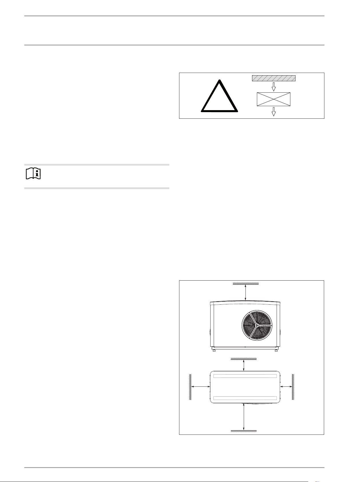
≥200
≥2000
≥500
≥1000
≥800
Safety
INSTALLATION
7. Safety
7.1 General safety instructions
- Only a qualified contractor should carry out installation,
commissioning, maintenance and repair of the appliance.
- We guarantee trouble-free function and operational reliability only if original accessories and spare parts intended for
the appliance are used.
7.2 Instructions, standards and regulations
Note
Observe all applicable national and regional regulations
and instructions.
8. Appliance description
The appliance protects the heating water lines against freezing up.
The integral frost protection circuit starts the circulation pump in
the heat pump circuit automatically at a condenser temperature
of 8 °C, and thereby ensures circulation in all water-carrying sections. If the temperature inside the buffer cylinder drops, the heat
pump starts automatically no later than when the temperature
falls below +5°C.
8.1 Standard delivery
The following are delivered with the appliance:
- Wiring diagram
- Condensate drain hose
9. Preparations
!
D0000060163
The appliance is designed for siting in front of a wall. Observe the
minimum clearances. If the appliance is installed in an open space
or on a roof, protect the air intake side. Do this by erecting a wall
to shield it against the wind.
9.1 Acoustic emissions
The appliance is louder on the air intake and air discharge sides
than on the two enclosed sides. Please therefore observe the information below.
For the sound power level, see chapter "Specification/Data table".
Ensure that the air intake direction is the same as the dom-
inant wind direction. Air should not be drawn in against the
wind.
Never direct the air intake or discharge towards noise sensi-
tive rooms of the house (e.g. bedrooms).
Lawn areas and shrubs help reduce the spread of noise.
Sound propagation can also be reduced by installing closely
spaced palisade fencing around the appliance. Observe the minimum clearances.
9.2 Minimum clearances
8.2 Accessories
8.2.1 Required accessories
- Heat pump manager with wall mounting casing, WPMW 3
8.2.2 Further accessories
- Wall mounting bracket WK 1
- T-support SK-WPL
- Mounting bracket MK 1
- Cylinder and hydraulic module HSBB 3
- Integral cylinder HSBC 200
- Hydraulic module HM (Trend)
- Pressure hoses DN 25
- Remote control for heating systems FEK
- Remote control for heating systems FE7
- Starting current limiter 25 A
- Safety temperature controller STB-FB
www.stiebel-eltron.com WPL 10 AC | WPL 10 ACS | 7
D0000022153
INSTALLATION
6
Preparations
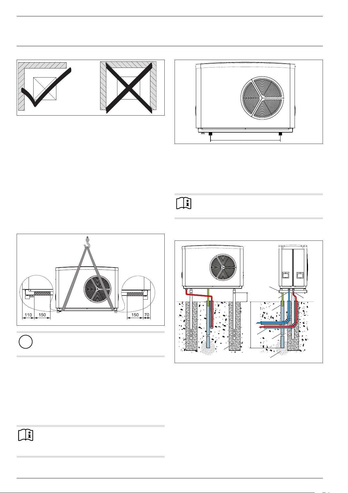
Never install the appliance in a recess. Two sides of the ap-
pliance must remain exposed.
Avoid installation on large, echoing floor areas (e.g. tiled
floors).
Avoid installation between reflective building walls. Reflect-
ing building walls can increase the noise level.
9.3 Preparation of the installation location
The substrate must be horizontal, level, solid and permanent.
Ensure that the appliance is accessible from all sides.
91�00�00�0036
890
Only use weather-resistant cables.
Protect the flow and return lines against frost with sufficient
thermal insulation. Provide thermal insulation in accordance
with applicable regulations.
Also protect all supply lines/cables against humidity, damage
and UV radiation by means of a conduit.
26�03�01�1683�
9.4 Transport
- Lifting straps to transport the appliance can be hooked into
the area highlighted in grey at the bottom of the support
frame.
Material losses
!
Protect the appliance against heavy impact during transport.
If the appliance needs to be tilted during transport only do so
for a short time on one of its longitudinal sides. The longer the
appliance is tilted, the greater the distribution of refrigerant in
the system. Wait approx. 30 minutes before starting the appliance
after it has been tilted.
9.5 Siting
Observe chapter "Sound emissions".
Note
Observe the clearance dimension in the following
diagram when using a T-support or wall mounting
bracket.
Note
When routing the condensate hose, observe chapter "Installation / Condensate drain".
Example: T-support SK-WPL
B
26�03�01�1548
A
4
A Depth of frost line
B 300
1 Heating flow
2 Heating return
3 Conduit for supply lines
4 Foundation
5 T-support
6 Gravel bed
7 Drainage pipe
8 Condensate drain
Observe the static limits of the T-support used.
5
2
8
3
7
1
D0000019236
8 | WPL 10 AC | WPL 10 ACS www.stiebel-eltron.com
INSTALLATION
4
6
Preparations
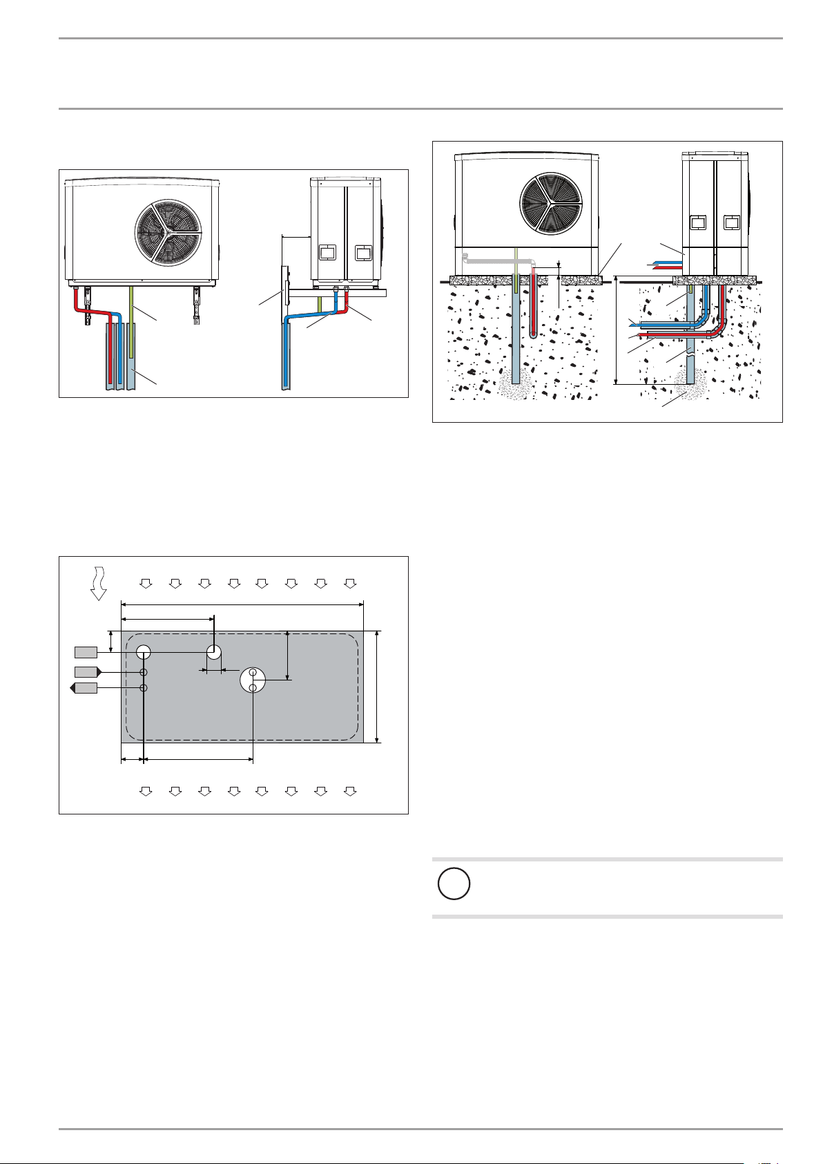
Example: Wall mounting bracket WK 1
≥200
5
3 1
2
1 Heating flow
2 Heating return
3 Condensate drain
4 Drainage pipe
5 Wall mounting bracket
Observe the static limits of the building wall and the wall
mounting bracket.
Example: Mounting bracket MK 1
b01
e02
e01
3
120
110
525
610
4
1350
80
1
265
5
2
b01 Entry electrical cables
e01 Heating flow
e02 Heating return
1 Air intake side
2 Air discharge side
3 Main wind direction
4 Condensate drain
5 Supply line outlet
635
4
5
9
2
70-80
A
D0000019244
8
2
1
3
7
A Depth of frost line
1 Heating flow
2 Heating return
3 Conduit for supply lines/cables
4 Foundation
5 Mounting bracket
6 Gravel bed
7 Drainage pipe
8 Condensate drain
9 Outlet for supply lines opt.
9.6 WPM 3 heat pump manager
A WPM3 heat pump manager is required to operate the appliance.
This controls the entire heating system.
9.7 Buffer cylinder
A buffer cylinder is recommended to ensure trouble-free appliance
operation.
The buffer cylinder provides hydraulic separation of the volume
flows in the heat pump circuit and heating circuit, and also serves
as an energy source for defrosting.
When operating without buffer cylinder, observe the details
D0000034844
specified in chapter "Minimum flow rate with individual room
controller by means of FEK / FE7 in the case of systems without buffer cylinder".
Material losses
!
A buffer cylinder with diffusion-proof insulation is essential for cooling mode.
1
D0000024451
www.stiebel-eltron.com WPL 10 AC | WPL 10 ACS | 9
INSTALLATION
Installation
9.8 Preparing the electrical installation
WARNING Risk of electrocution!
Carry out all electrical connection and installation work
in accordance with national and regional regulations.
WARNING Risk of electrocution!
The connection to the power supply must be in the form
of a permanent connection. The appliance must be able
to be separated from the power supply by an isolator
that disconnects all poles with at least 3mm contact
separation. This requirement can be met by contactors,
isolators, fuses, etc.
Material losses
!
The specified voltage must match the mains voltage. Observe the type plate.
Material losses
!
Provide separate fuses for the 3 power circuits (for the
appliance, the electric emergency/booster heater and the
control unit).
Always connect "L" for the heat pump and the control unit to
the same phase.
Where required, you can install our starting current limiter with
25 A for the WPL 10 AC (see "Additional accessories").
Route cables with the following cross-sections in accordance
with the respective fuse rating:
10. Installation
10.1 Siting
When installing the appliance, observe the air intake
direction.
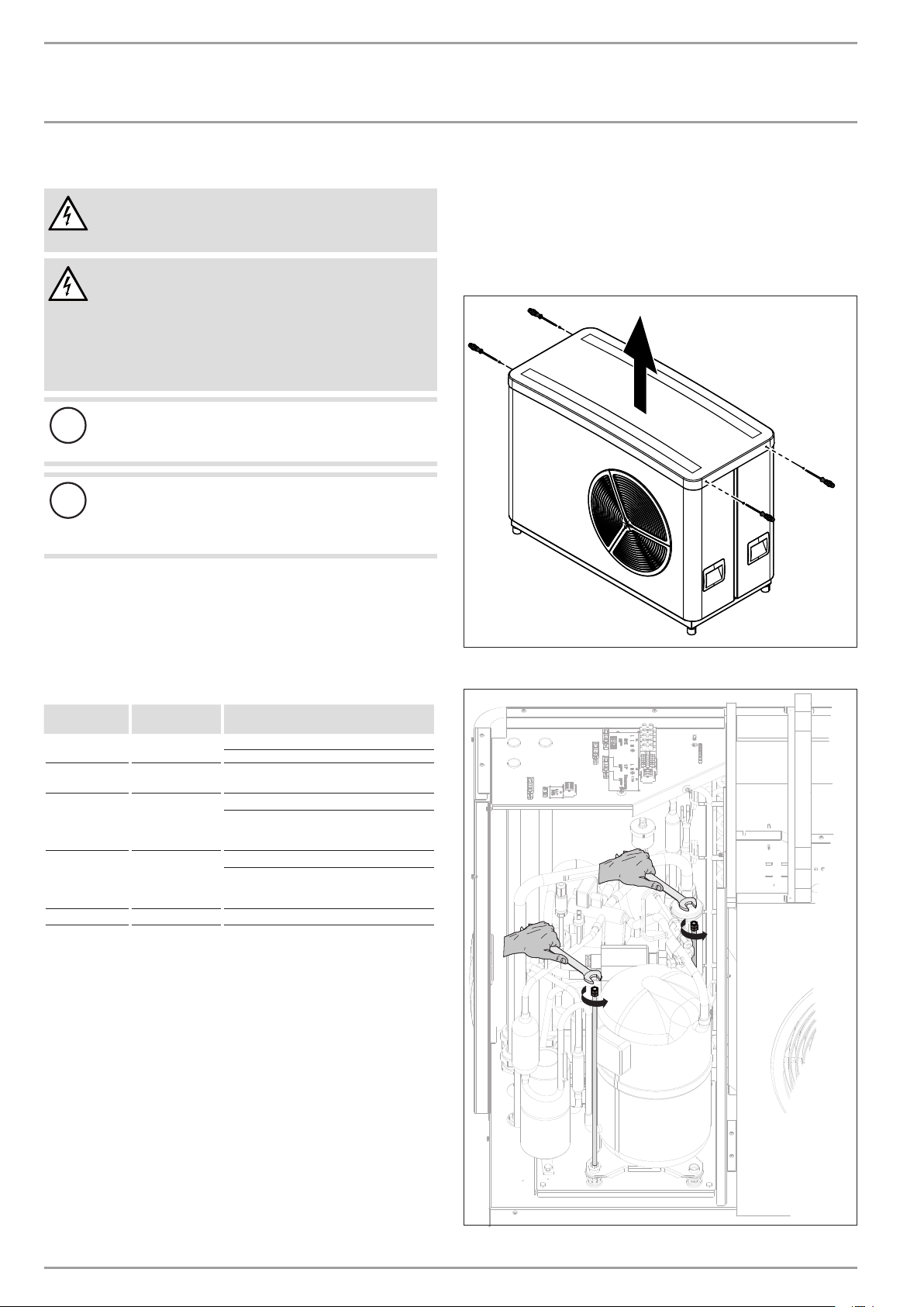
Position the standard appliance on the prepared substrate.
26�03�01�1544
Remove the cover.
MCB/fuse
rating
C 25 A Heat pump
C 16 A Heat pump
B 35 A
B 16 A
B 16 A Control 1.5 mm²
The electrical data is provided in the chapter "Specification" . You
require a J-Y (St) 2x2x0.8mm² cable as BUS cable.
Assignment Cable cross-section
(single phase)
(3-phase)
Electric emergen-
cy/booster heater
(DHC)
(single phase)
Electric emergency/booster heater
(DHC)
(3-phase)
2.5 mm² for routing above the surface
4.0 mm² for routing through a wall
2.5 mm²
6.0 mm² for routing through a wall
4.0 mm² when routing multi-core cables
on a wall or in an electrical conduit on
a wall
2.5 mm
1.5 mm² with only two live cores and
routing on a wall or in an electrical conduit on a wall.
10 | WPL 10 AC | WPL 10 ACS www.stiebel-eltron.com
26�03�01�1550
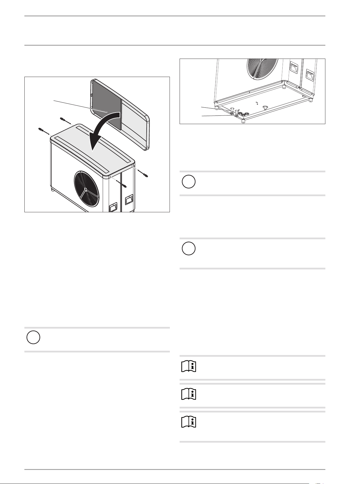
INSTALLATION
Installation
Remove the transport locks (threaded rods) from the
compressor.
1
1
2
1 Heating circuit flow
2 Heating circuit return
Connect the heat pump to the heating circuit. Check for
tightness.
10.4 Oxygen diffusion
Material losses
!
Avoid open heating systems and plastic pipes in underfloor heating systems which are permeable to oxygen.
26�03�01�1552
1 Sound insulation
Position the cover on the appliance.
Secure the cover with the four screws.
10.2 Heating water connection
The heat pump heating system must be installed by a qualified
contractor in accordance with the water installation drawings that
are part of the technical documents.
Thoroughly flush the pipework before connecting the heat
pump. Foreign matter, such as welding pearls, rust, sand
or sealant will impair the operational reliability of the heat
pump and can result in the heat pump condenser becoming
blocked.
10.3 Flow and return connection
Material losses
!
Insulate the heating flow and return lines with vapour
diffusion-proof material.
Fit an anti-vibration mount at least 1 m long to the connectors.
Structure-borne noise is largely prevented by the anti-vibration
construction of the heat pump and by the flexible pressure hoses,
which act as anti-vibration mounts.
Take the position of the heating flow and return from the fol-
lowing figure:
In underfloor heating systems with plastic pipes that are per-
26�03�01�1759
meable to oxygen and in open vented heating systems, oxygen
diffusion may lead to corrosion on the steel components of the
heating system (e.g. on the indirect coil of the DHW cylinder, on
buffer cylinders, steel heating elements or steel pipes).
Material losses
!
The products of corrosion (e.g. rusty sludge) can settle in
the heating system components and can result in a lower
output or fault shutdowns due to reduced cross-sections.
10.5 Filling the heating system
10.5.1 Water quality
Carry out a fill water analysis before the system is filled. This may,
for example, be requested by the relevant water supply utility.
To avoid damage as a result of scaling, it may be necessary to
soften or desalinate the fill water. Always observe the fill water
limits specified in the "Specification / Data table" chapter.
Recheck these limits 8-12 weeks after commissioning and as
part of the annual system maintenance.
Note
With a conductivity >1000 μS/cm, desalination treatment
is recommended in order to avoid corrosion.
Note
If you treat the fill water with inhibitors or additives, the
same limits as for desalination apply.
Note
Suitable appliances for water softening, as well as for
filling and flushing heating systems, can be obtained via
trade suppliers.
www.stiebel-eltron.com WPL 10 AC | WPL 10 ACS | 11
 Loading...