


STIEBEL ELTRON WPF 5 basic, WPF 7 basic, WPF 5 S basic, WPF 16 basic, WPF 7 S basic Operation And Installation
...
OPERATION AND INSTALLAT ION
Brine | water heat pumps
» WPF 5 basic
» WPF 7 basic
» WPF 10 basic
» WPF 13 basic
» WPF 16 basic
» WPF 5 S basic
» WPF 7 S basic
» WPF 10 S basic

CONTENTS
SPECIAL INFORMATION
OPERATION
1. General information �����������������������������������������3
1.1 Safety instructions ����������������������������������������������� 3
1.2 Other symbols in this documentation ����������������������� 4
1.3 Units of measurement ������������������������������������������ 4
1.4 Standardised output data �������������������������������������� 4
2. Safety ���������������������������������������������������������� 4
2.1 Intended use ������������������������������������������������������ 4
2.2 Safety information ����������������������������������������������� 4
2.3 Test symbols ������������������������������������������������������ 4
3. Appliance description ���������������������������������������4
3.1 Energy saving tip ����������������������������������������������� 5
4. Operation �����������������������������������������������������5
4.1 Operation ���������������������������������������������������������� 6
4.2 Essential facts in brief ������������������������������������������ 6
4.3 Adjustments at control level 1 �������������������������������� 7
4.4 Overview of control level 2������������������������������������� 7
4.5 Adjustments at control level 2 �������������������������������� 8
4.6 Remote control FE7 �������������������������������������������� 17
4.7 Remote control FEK �������������������������������������������� 17
5. Maintenance and care ������������������������������������� 17
6. Troubleshooting �������������������������������������������� 17
6.1 Other problems ������������������������������������������������� 17
INSTALLATION
7. Safety �������������������������������������������������������� 18
7.1 General safety information ����������������������������������� 18
7.2 Instructions, standards and regulations ������������������� 18
8. Appliance description ������������������������������������� 18
8.1 Mode of operation ���������������������������������������������� 18
8.2 Standard delivery ����������������������������������������������� 18
9. Preparations ������������������������������������������������ 18
9.1 General information �������������������������������������������� 18
9.2 Electrical installation������������������������������������������� 19
9.3 Buffer cylinder �������������������������������������������������� 19
10. Mounting ���������������������������������������������������� 19
10.1 Handling ���������������������������������������������������������� 19
10.2 Positioning ������������������������������������������������������� 19
10.3 Removing the casing panels ���������������������������������� 20
10.4 Installing the heat source system ��������������������������� 20
10.5 Heating water connection ������������������������������������� 22
10.6 Oxygen diffusion ������������������������������������������������ 22
10.7 Filling the heating system ������������������������������������ 22
10.8 Venting the heating system ����������������������������������� 22
10.9 Minimum flow rate of heat sink for WPF 5-16 basic ����� 23
10.10 Flow rate of heat sink for WPF 5-10 S basic ��������������� 24
10.11 DHW heating ����������������������������������������������������� 24
10.12 Electrical connection ������������������������������������������� 24
10.13 Fitting the casing parts ���������������������������������������� 28
10.14 installation ������������������������������������������������������� 29
10.15 High limit safety cut-out for underfloor heating
systems STB-FB ������������������������������������������������� 29
10.16 Remote control FE7 �������������������������������������������� 30
10.17 Remote control FEK �������������������������������������������� 30
11. Commissioning ��������������������������������������������� 30
11.1 Checks before commissioning�������������������������������� 30
11.2 Heating curve adjustment during commissioning ������� 31
11.3 Operation and control ����������������������������������������� 31
11.4 Taking the appliance out of use ������������������������������ 31
11.5 Heat pump manager commissioning summary ���������� 32
11.6 Heat pump manager commissioning ����������������������� 34
11.7 WPMiw commissioning report ������������������������������� 41
12. Settings ����������������������������������������������������� 42
12.1 Standard settings ����������������������������������������������� 42
12.2 Heating and DHW programs ����������������������������������42
12.3 Appliance handover �������������������������������������������� 42
13. Troubleshooting �������������������������������������������� 43
13.1 Fault display ����������������������������������������������������� 43
13.2 Resetting the high limit safety cut-out ��������������������� 44
13.3 Fault list parameter �������������������������������������������� 45
14. Maintenance ������������������������������������������������ 45
15. Specification ������������������������������������������������ 46
15.1 Connections ������������������������������������������������������ 46
15.2 Installation dimensions ���������������������������������������� 47
15.3 Wiring diagram WPF 5 basic ��������������������������������� 48
15.4 Wiring diagram WPF 7 basic | WPF 10 basic | WPF 13
basic | WPF 16 basic �������������������������������������������� 50
15.5 Wiring diagram WPF 5-10 S basic ��������������������������� 52
15.6 Output diagrams WPF 5 basic �������������������������������� 54
15.7 Output diagrams WPF 7 basic �������������������������������� 56
15.8 Output diagrams WPF 10 basic ������������������������������58
15.9 Output diagrams WPF 13 basic ������������������������������ 60
15.10 Output diagrams WPF 16 basic ������������������������������ 62
15.11 Output diagrams WPF 5 S basic ������������������������������ 64
15.12 Output diagrams WPF 7 S basic ������������������������������ 65
15.13 Output diagrams WPF 10 S basic ���������������������������� 66
15.14 Data table WPF 5-16 basic ������������������������������������ 67
15.15 Datentabelle WPF 5-10 S basic ������������������������������� 69
15.16 Data table WPMiw ���������������������������������������������� 70
GUARANTEE
ENVIRONMENT AND RECYCLING
2 | WPF basic www.stiebel-eltron.com
SPECIAL INFORMATION
General information
SPECIAL INFORMATION
- The appliance may be used by children aged8
and up and persons with reduced physical, sensory or mental capabilities or a lack of experience
and know-how, provided that they are supervised
or they have been instructed on how to use the
appliance safely and have understood the resulting risks. Children must never play with the appliance. Children must never clean the appliance
or perform user maintenance unless they are
supervised.
- Use a permanent connection to the power supply.
Ensure the appliance can be separated from the
power supply by an isolator that disconnects all
poles with at least 3mm contact separation.
- Maintain the minimum clearances to ensure trouble-free operation of the appliance and facilitate
maintenance work.
- The COOLING MODE parameter must only be set if
there is a suitable hydraulic circuit.
- The COOLING MODE parameter will only be
shown if a FEK or FE7 remote control is connected. The cooling mode is only possible in summer.
- Maintenance work, such as checking the electrical safety, must only be carried out by a qualified
contractor.
OPERATION
1. General information
The chapters „Special Information“ and „Operation“ are intended
for both the user and qualified contractors.
The chapter „Installation“ is intended for qualified contractors.
Note
Read these instructions carefully before using the appliance and retain them for future reference.
Pass these instructions on to a new user if required.
1.1 Safety instructions
1.1.1 Structure of safety instructions
KEYWORD Type of risk
Here, possible consequences are listed that may result
from failure to observe the safety instructions.
Steps to prevent the risk are listed.
1.1.2 Symbols, type of risk
Symbol Type of risk
1.1.3 Keywords
Injury
Electrocution
- We recommend a regular inspection (to establish
the current condition of the system), and maintenance by a qualified contractor if required (to
return the system to its original condition).
- Never interrupt the power supply, even outside
the heating period. The system’s active frost protection is not guaranteed if the power supply is
interrupted.
- There is no need to shut the system down in
summer. The heat pump manager has an automatic summer/winter changeover.
KEYWORD Meaning
DANGER Failure to observe this information will result in serious
injury or death.
WARNING Failure to observe this information may result in serious
injury or death.
CAUTION Failure to observe this information may result in non-seri-
ous or minor injury.
www.stiebel-eltron.com WPF basic | 3
OPERATION
Safety
1.2 Other symbols in this documentation
Note
General information is identified by the adjacent symbol.
Read these texts carefully.
Symbol Meaning
This symbol indicates that you have to do something. The ac-
tion you need to take is described step by step.
Material losses
(appliance damage, consequential losses and environmental pollution)
Appliance disposal
1.3 Units of measurement
Note
All measurements are given in mm unless stated otherwise.
1.4 Standardised output data
Explanations to determine and interpret the specified standardised
output data
1.4.1 Standard: EN 14511
The output data specifically mentioned in text, diagrams and
technical datasheets has been determined in line with the test
conditions described in the standard shown in the heading of
this chapter.
Generally, these standardised test conditions will not fully meet
the conditions found at the installation site of the system user.
Depending on the chosen test method and the extent to which
the selected method deviates from the conditions described in the
standard shown in the heading of this chapter, any deviations can
have a considerable impact. Further factors that have an influence
on the test values are the measuring equipment, the system configuration, the age of the system and the flow rates.
A confirmation of the specified output data can only be obtained
if the conditions applicable to the relevant test match those of the
standard shown in the heading of this chapter.
2. Safety
2.1 Intended use
The appliance is designed to:
- heat rooms.
- heat DHW.
Observe the operating limits listed in chapter “Specification”.
The appliance is intended for domestic use, i.e. h. it can be used
safely by untrained persons. The appliance can also be used in a
non-domestic environment, e.g. in a small business, as long as it
is used in the same way.
Any other use beyond that described shall be deemed inappropriate. Observation of these instructions and of instructions for any
accessories used is also part of the correct use of this appliance.
Any changes or conversions to the appliance void any warranty.
2.2 Safety information
Observe the following safety information and regulations.
- The electrical installation and installation of the heating circuit must only be carried out by a recognised, qualified contractor or by our customer service engineers.
- Contractors are responsible for adherence to all currently applicable regulations during installation and commissioning.
- Operate the appliance only when fully installed and with all
safety equipment fitted.
- Protect the appliance from dust and dirt ingress during
building work.
WARNING Injury
!
The appliance may be used by children aged 8 and up
and persons with reduced physical, sensory or mental
capabilities or a lack of experience provided that they
are supervised or they have been instructed on how to
use the appliance safely and have understood the resulting risks. Children must never play with the appliance.
Children must never clean the appliance or perform user
maintenance unless they are supervised.
WARNING Injury
!
For safety reasons, only operate the appliance with
the casing closed.
2.3 Test symbols
See type plate on the appliance.
3. Appliance description
The WPF is a heating heat pump designed as a ground source
heat pump. The heat pump extracts energy from the heat source
medium at a low temperature level. This extracted energy is then
transferred to the heating water at a higher level, enriched by
the electric energy drawn by the compressor. Subject to the heat
source temperature, the heating water can be heated up to a flow
temperature of 60 °C.
Inside the WPF, a heating circuit pump and a three-way valve have
been integrated for diverting the flow either to the heating circuit
4 | WPF basic www.stiebel-eltron.com
OPERATION
Operation
or the DHW circuit. DHW is heated by pumping the heating water,
which has been heated by the heat pump, through an indirect coil
in the DHW cylinder, where it transfers its energy to the DHW.
The appliance is equipped with an electric emergency/booster
heater (DHC). If the dual mode point is undershot in mono mode
operation, the electric emergency/booster heater is activated to
safeguard heating operation and the provision of high DHW temperatures. If the same thing happens in mono energetic operation,
the electric emergency/booster heater is activated as a booster
heater.
The equipment is regulated by an integral, weather-compensated
return temperature control (WPMiw heat pump manager).
The WPMiw also regulates the DHW heating to the required temperature. DHW heating will be completed automatically by an
integral electric booster heater, if either the high pressure sensor
or the hot gas limiter of the heat pump responds during DHW
heating, subject to the ECO function being enabled. Subject to the
ECO function being enabled, the DHW heating will terminate and
the set DHW value overwritten with the actual DHW temperature
that has been achieved.
The WPMiw also controls the integral electric booster heater. No
other heat source can be switched.
3.1 Energy saving tip
- Heat pumps operate with particular economy and environmental responsibility when they work with a maximum flow
temperature of 35 °C. Low flow temperatures can be achieved
by using area heating systems (e.g. underfloor heating or
wall heating systems).
- Size radiators so that the maximum required flow temperature does not exceed 45 °C.
- Activating the control parameter “Pump cycling” can reduce
the power drawn by the circulation pump. In this connection,
refer to your local heating contractor.
- When activating the “DHW ECO” parameter, the heat pump
heats DHW exclusively on its own, i.e. without the additional
electric booster heater. In that case, the DHW temperature is
automatically limited to that value, which the heat pump can
actually achieve. If, for reasons of pasteurisation, you want to
heat the cylinder to 60 °C at least once every day, activate the
“PASTEURISATION” parameter. In this connection, refer to
your local heating contractor.
Summary of WPMiw functions
- RS 232 interface for adjustment and monitoring via a PC
- System expansion through the FEK and FE7 remote control
units
- Input of the system and heat pump frost protection limits
- At least 24 h power reserve for the clock
- Automatic pump kick-start
- Reset option
- Stored fault list with precise fault code indication, together
with date and time display
- Fast and precise fault diagnosis with a system analyser incl.
temperature scanning of heat pumps and peripherals without
additional equipment
- Factory settings for time switch programs for all heating and
DHW circuits
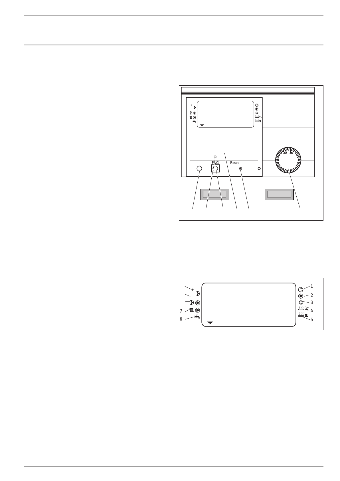
4. Operation
WPMiw heat pump manager
ROOM TEMP HCI
Time / Date
DHW temp.
Room temp. 1
Room temp. 2
Raumtemp. 1
Raumtemp. 2
Warmwassertemp.
Heizkurven
Heating curves
Zeit / Datum
Info temperatures
Heizprogramme
Holiday / Party prog.
Info Temperaturen
Ferien / Partyprog.
PRGPC Reset Auto
1 Rotary selector
2 Rotary selector Reset / Auto
3 Appliance menu
4 Programming key
5 Programming indicator
6 Optical interface RS 232
System status display
10
ROOM TEMP HCI
9
8
7
6
1 Compressor 1
2 Buffer cylinder primary pump
3 Cooling (only with a suitable hydraulic circuit)
4 Electric emergency/booster heater (DHW heating)
5 Electric emergency/booster heater (heating)
6 DHW heating
7 Circulation pump, heating circuit 1 “radiator circuit”
8 Circulation pump, heating circuit 2 “mixer circuit”
9 Mixer close
10 Mixer open
Start up
Heating prog
DHW program
Inbetriebnahme
Warmwasserprog.
2
3
1456
26�03�01�0073
1
2
3
4
5
26�03�01�1572
www.stiebel-eltron.com WPF basic | 5
OPERATION
Operation
4.1 Operation
The operation is split over three control levels. Control levels 1
and 2 are accessible to users and contractors alike. Control level
3 is reserved for qualified contractors:
1. control level (control flap closed)
This enables the adjustment of operating modes, such as standby
mode, programmed operation, constant day or setback mode, etc.
2. control level (control flap open)
This enables system parameters, such as room temperatures, DHW
temperatures, heating programs, etc. to be adjusted.
3. control level (for contractors only)
This level is protected by a code and should only be used by a
contractor. Here, you can determine the specific details regarding
the heat pump and heating system.
4.2 Essential facts in brief
Settings
All settings follow the same pattern:
Opening the control flap toggles the manager into programming
mode. An indicator symbol
play at system parameter Room temp. 1. Turning the rotary selector allows you to move the indicator to the system parameter
you want to change.
To change the system parameter, press
dicator above illuminates, you can modify the current value by
turning the rotary selector . Press the key again; the indicator
then extinguishes and the new set value has been saved. You can
modify further values for this parameter by pressing again, if
the red indicator has not been extinguished above . The programming step can only be terminated when the red indicator
has extinguished.
Terminating the programming process
You can terminate the programming process after entering and saving the required parameter changes by closing the control flap. If you
want to make further changes, turn the rotary selector
display shows BACK, then press
ous level. Closing the control flap with illuminated indicator above
returns the manager into its original position. The modified
value will then not be saved.
is shown at the bottom of the dis-
. Whenever the red in-
until the
. This will return you to the previ-
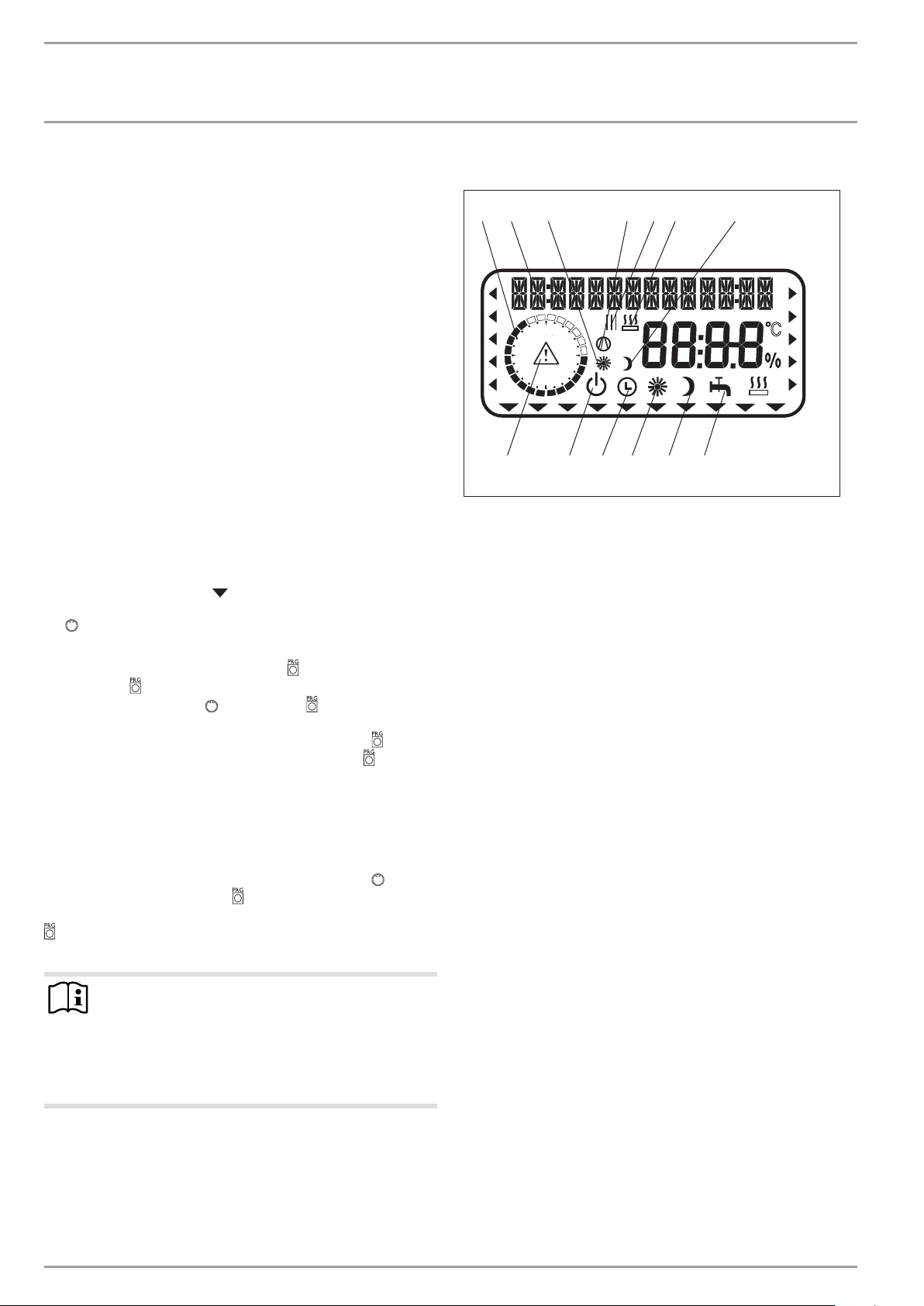
Display including all display elements
2 765431
24
18
13 12 11 10 9 8
1 Heating times for central heating and DHW (black)
2 14-digit plain text display
3 Day mode for heating circuit 1
4 Compressor running
5 Switching time pairs for central heating and DHW operation
6 2. heat source running
7 Setback mode for heating circuit 1
8 DHW mode
9 Constant setback mode
10 Constant day mode
11 Automatic mode
12 Standby mode
13 Fault message (flashing)
6
12
C
V
26�03�01�0075
Note
During commissioning, a system check will be implemented, e.g. all sensors that are currently connected are
displayed upon request. Sensors not connected before
the system went ‚live‘ are not registered by the manager
and are therefore not displayed. The indicator symbol
skips such system parameters.
Example: The system parameters DHW TEMP and DHW PROGRAM
will be skipped if, during commissioning, the DHW cylinder sensor
was not connected. und Warmwasserprog. übersprungen. Values
for these parameters, therefore, cannot be programmed.
6 | WPF basic www.stiebel-eltron.com
OPERATION
Operation
4.3 Adjustments at control level 1
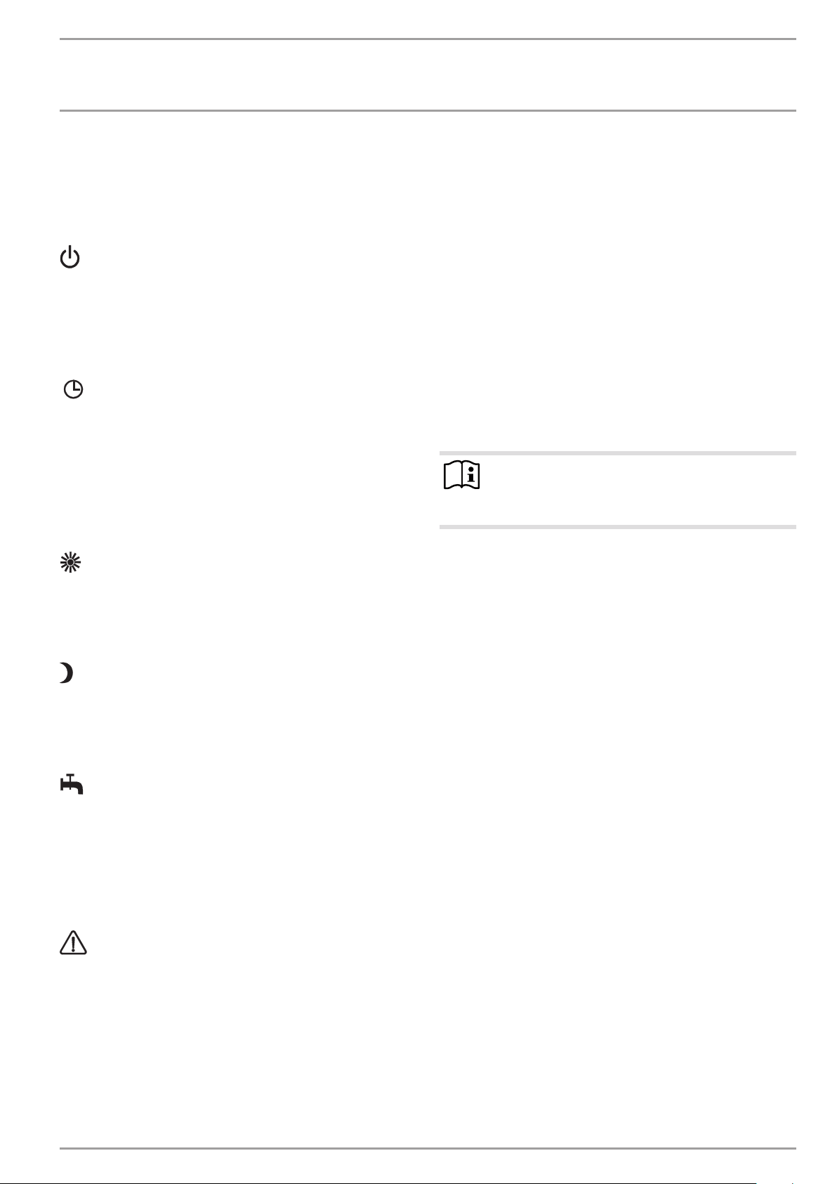
4.3.1 Operating modes
The operating modes are changed by turning rotary selector with
the control flap closed.
Standby mode
Frost protection is activated for heating and DHW mode. The display indicates frost protection when the flap is closed. The set
DHW value is fixed at 10 °C, the set heating flow value is calculated
based on a set room temperature of 5 °C.
Application: during holidays.
Automatic mode
Heating subject to time switch program (applies to heating circuits
1 and 2); changeover between day and setback temperatures. DHW
in accordance with a time switch program; changeover between
day and setback temperature, see point 4. In this operating mode,
an additional sun or moon symbol is displayed to indicate whether
heating circuit 1 is currently in day or setback mode. The remote
control is only active in this mode.
Application: When DHW and central heating are required.
Constant day mode
The heating circuit is constantly held at the day temperature (applicable to heating circuit 1 and heating circuit 2). DHW in accordance with a time switch program.
Application: Low energy houses without setback mode.
Constant setback mode
The heating circuit is constantly held at the setback temperature
(applicable to heating circuit 1 and heating circuit 2). DHW in
accordance with a time switch program.
Application: during weekends away.
DHW mode
DHW heating is regulated by a time switch program. If a time
program is enabled, the water inside the DHW cylinder is heated
to the set day temperature. At all other times, the water is heated to the set night temperature. Frost protection is activated for
heating operation.
Application: The heating season has ended; only DHW should be
generated.
Fault message (flashing)
Indicates faults in the heat pump system.
Notify your local contractor
4.4 Overview of control level 2
To access control level 2,
open the control flap.
Select the required parameter with the rotary selector.
The display shows the relevant parameter in plain text and an
arrow indicating the parameter’s location in the control level.
ROOM TEMP HC1
Here you can select the set room temperature for day and setback
mode for heating circuit 1.
ROOM TEMP HC2
Here you can select the set room temperature for day and setback
mode for heating circuit 2. The display ROOM TEMP2 will only be
displayed, if the mixer flow sensor for heating circuit 2 has been
connected.
Note
The actual room temperature can also be scanned if the
FE7 or FEK remote control has been connected and allocated to HC1 or HC2.
DHW TEMP
Here you can allocate a set day and night temperature to the
temperature inside the DHW cylinder.
TIME/DATE
Here you can adjust the time and summertime.
At the factory, summertime is set to begin on 25 March and to
end on 25 October.
HOLIDAY/PARTY
You can indicate the length of your holiday using the holiday program menu (start date, end date). The heat pump system operates in setback mode for the selected period. Frost protection is
activated for the DHW cylinder.
The party program menu item allows you to extend the day mode
by a few hours.
Temperatures
Here you can scan the heat pump or heat pump system sensor
temperatures, comparing set with actual values, the heating curve
gap, etc.
HEATING CURVES
Here you can select a heating curve each for heating circuit 1
and heating circuit 2. The room temperature will only remain
constant, irrespective of the outside temperature, if the correct
heating curve has been selected for the relevant type of building.
Selecting the correct heating curve is therefore vitally important.
HEATING PROG
Here you can adjust associated heating programs for heating circuits 1 and 2.
www.stiebel-eltron.com WPF basic | 7
OPERATION
Operation
DHW PROGRAM
Here you select the times when the appliance will control DHW
heating using the set day value. At all other times, the appliance
controls DHW heating using the set night value.
COMMISSIONING
Note
The commissioning level (control level 3) may only be
altered by your contractor.
Here you need to determine the settings of control level 2 and the
system-specific parameters. These parameters are adjusted at
control level 3, access to which is protected by code.
Check all parameters in sequence, and enter all selected values
into the column (system value) provided in the commissioning
report.
4.4.1 Special features of the WPF in cooling mode
For the WPF in cooling mode, your qualified contractor selects
the room temperature for cooling mode at control level 3. Cooling
commences when the room temperature exceeds the set room
temperature.
Cooling terminates when the actual room temperature is 2 K lower
than the set room temperature.
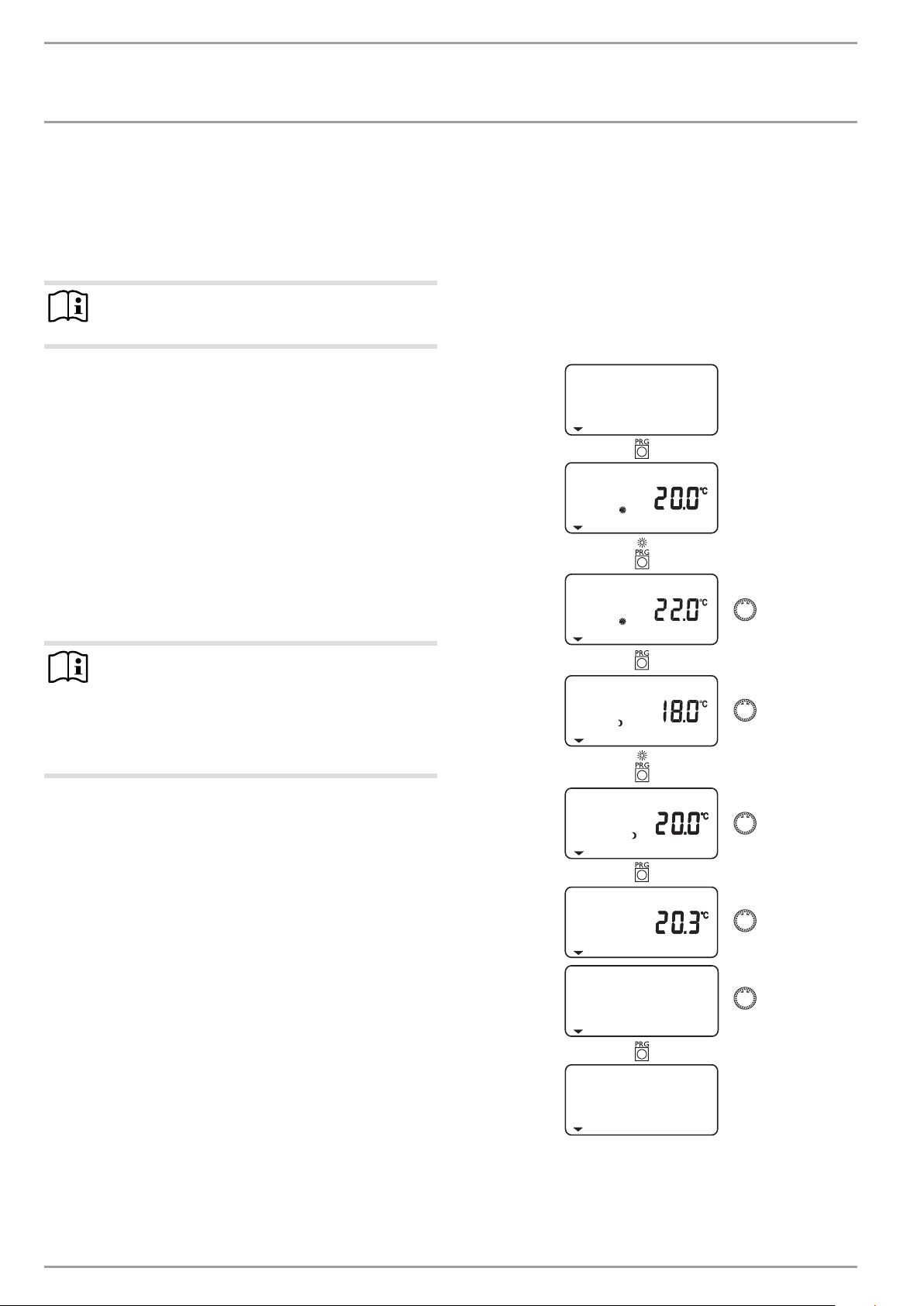
4.5 Adjustments at control level 2
To make any adjustments at control level 2, open the control flap.
4.5.1 Room temperature HC 1
With menu item ROOM TEMP HC1, you can select the set room
temperature for day and setback mode for heating circuit 1. Changing this parameter results in a parallel offset of the heating curve.
The actual room temperature can also be scanned, as soon as the
FE7 or FEK remote control has been connected and allocated to
heating circuit 1.
ROOM TEMP HC1
SET ROOM T DAY
SET ROOM T DAY
Note
For cooling via cooling surfaces (underfloor heating or
wall heating systems), you also require the FEK remote
control. For cooling via fan-assisted convectors, you also
require the FEK or FE7 remote control.
Cooling via radiators would lead to moisture damage and
is therefore not permissible!
SET ROOM T NGT
SET ROOM T NGT
ACTUAL ROOM T
BACK
ROOM TEMP HC1
8 | WPF basic www.stiebel-eltron.com
OPERATION
Operation
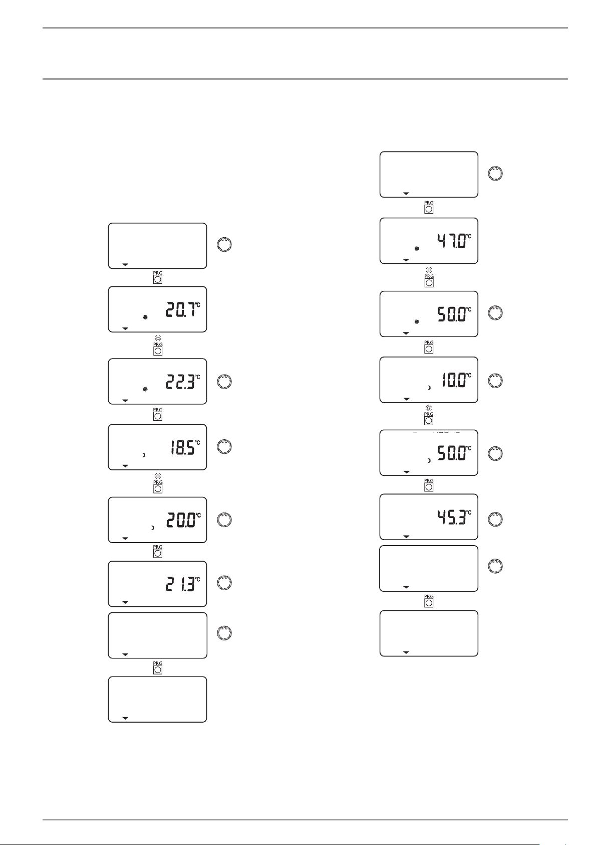
4.5.2 Room temperature, heating circuit 2
With menu item ROOM TEMP HC2, you can select the set room
temperature for day and setback mode for heating circuit 2. You
can change the room temperature, if you feel rooms are either
too hot or too cold. ROOM TEMP HC2 will only be displayed if the
mixer flow sensor is connected.
The actual room temperature can also be scanned, as soon as the
FE7 or FEK remote control has been connected and allocated to
heating circuit 2.
ROOM TEMP HC2
SET ROOM T DAY
SET ROOM T DAY
4.5.3 DHW temperature
With parameter 9, you can allocate a set day and night temperature to the temperature inside the DHW cylinder.
DHW TEMP
SET DHW T DAY
SET DHW T DAY
SET DHW T NGT
SET ROOM T NGT
SET ROOM T NGT
ACTUAL ROOM T
BACK
ROOM TEMP HC2
SET DHW T NGT
ACTUAL DHW T
BACK
DHW TEMP
www.stiebel-eltron.com WPF basic | 9
OPERATION
Operation
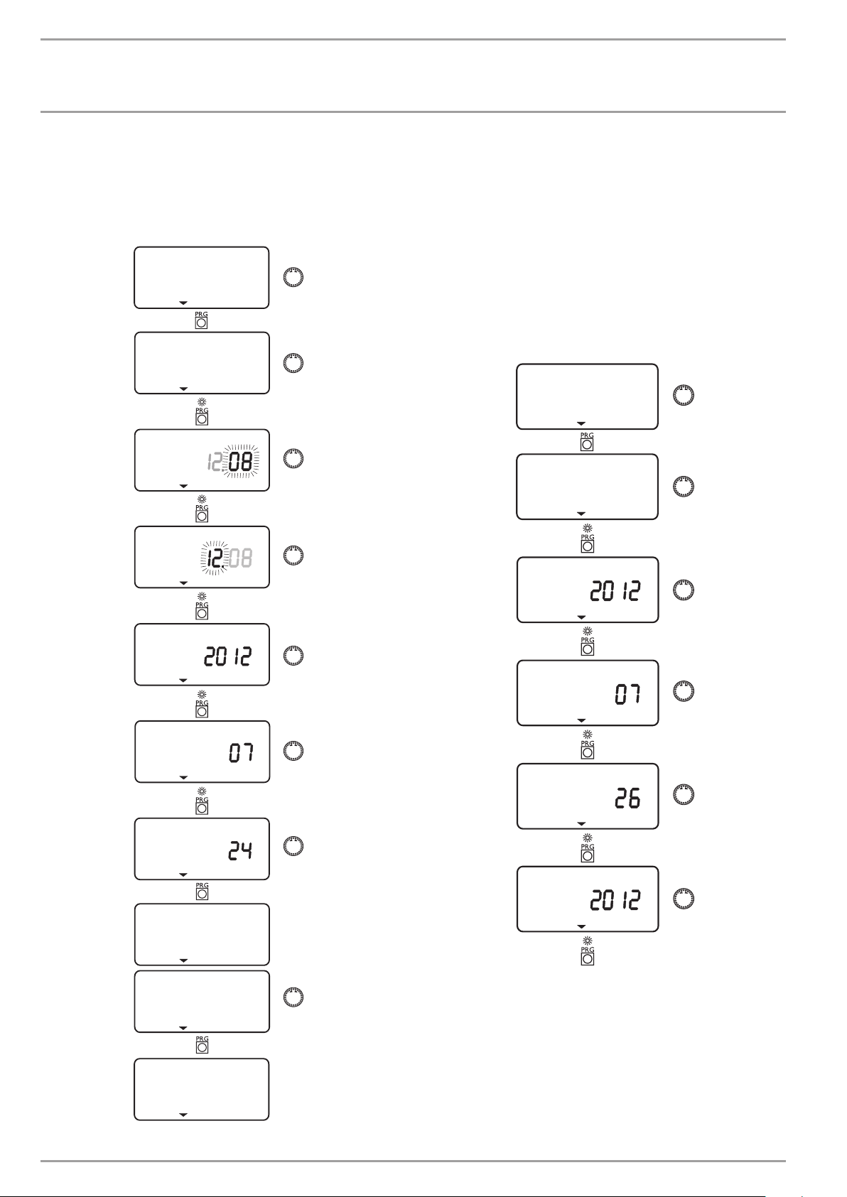
4.5.4 Time and date
You can adjust the time and summertime with the TIME/DATE
menu item.
At the factory, summertime is set to begin on 25 March and to
end on 25 October.
TIME/DATE
SET CLOCK
TIME
TIME
4.5.5 Holiday and party program
In HOLIDAY MODE, the heat pump system runs in setback mode
and frost protection for DHW heating is enabled. Holiday mode
is displayed when the flap is closed. For the start of the holidays,
the year, month and day are entered; also enter the year, month
and day for the end of the holidays. The start time is 0:00 h on the
first day of the holidays. The end time is 24:00 h on the day the
holiday ends. After the holiday period has expired, the heat pump
system operates again in accordance with the previous heating
and DHW program.
In PARTY MODE, you can extend the day mode for central heating
by a few hours. This is displayed with the flap closed.
HOLIDAY/PARTY
HOLIDAY
YEAR
MONTH
DAY
SET CLOCK
YEAR START
MONTH START
DAY START
YEAR END
BACK
TIME/DATE
10 | WPF basic www.stiebel-eltron.com
OPERATION
Operation
MONTH END
DAY END
HOLIDAY
BACK
HOLIDAY/PARTY
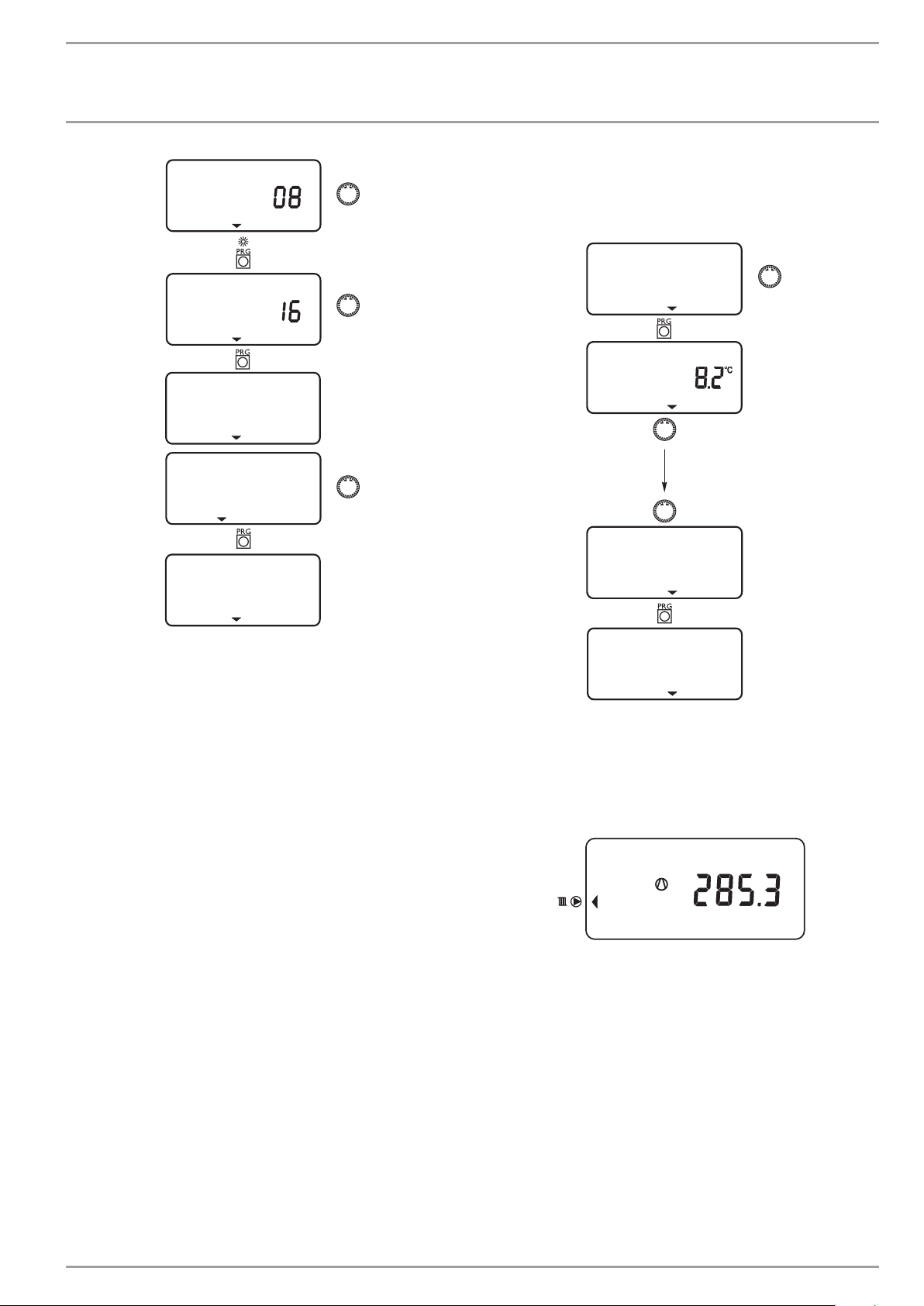
4.5.6 Temperatures
Under menu item TEMPERATURES, you can scan values of the heat
pump or heat pump system.
TEMPERATURES
OUTSIDE
BACK
TEMPERATURES
Actual or set temperatures will not be displayed if the corresponding sensor is not connected.
Example:
Compressor heat amount in heating mode since 0:00 h today in
KWh.
HEAT AMOU DAY kwh
www.stiebel-eltron.com WPF basic | 11
OPERATION
Operation
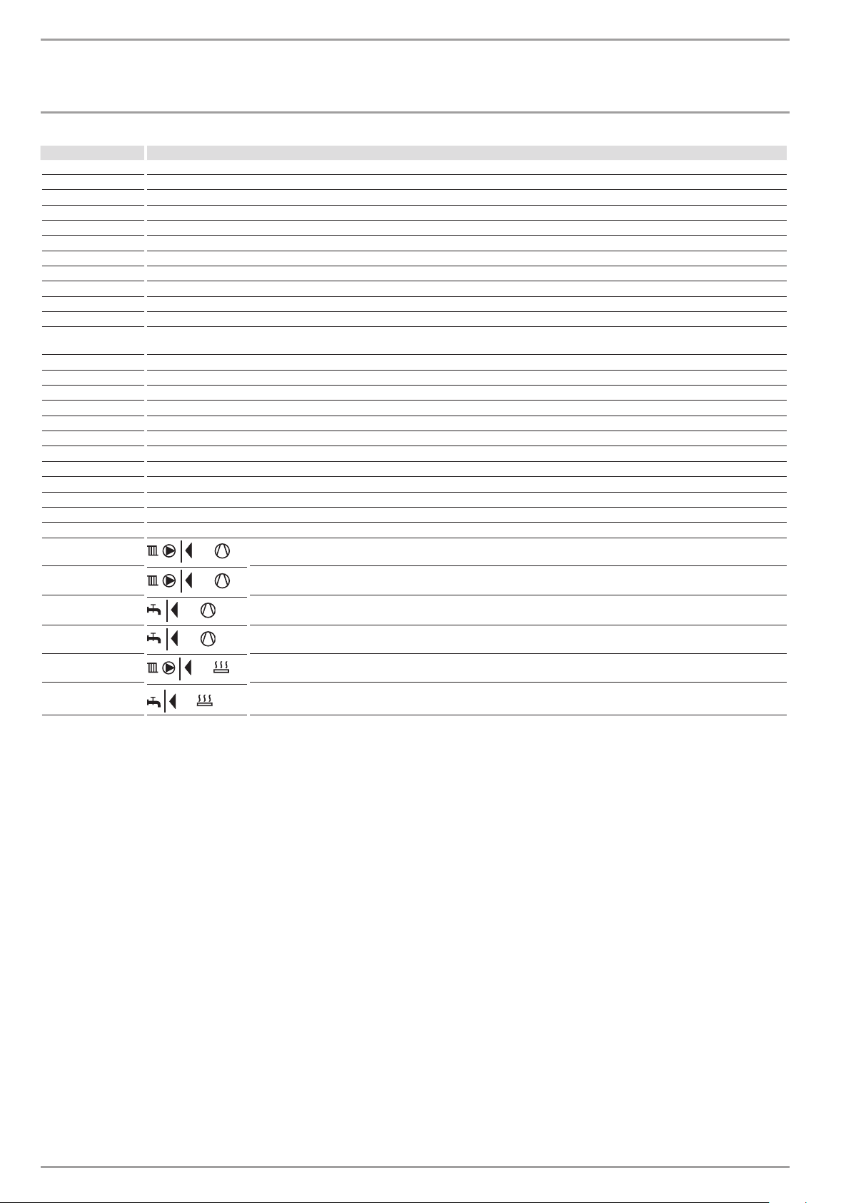
INFO WPM Meaning
external Outside temperature
ACT ROOM T FE7 Actual room temperature for heating circuit 1 (HC1) or heating circuit 2 (HC2) (will only be displayed if the FE7 remote control is connected)
SET ROOM T FE7 Set room temperature for heating circuit 1 or heating circuit 2 (will only be displayed if the FE7 remote control is connected)
REL HUMIDITY Relative humidity
DEW POINT TEMP Dew point temperature
SET DHW TEMP Set DHW temperature
ACTUAL RTRN T Actual heat pump return temperature - heating circuit 1
SET RTRN TEMP Set heat pump return temperature for heating circuit 1 (HC1). Fixed temperature is displayed for fixed temperature control
ACTUAL MIXER T Actual mixer flow temperature - heating circuit 2
SET MIXER TEMP Set mixer flow temperature - heating circuit 2
FIXED VALUE Set fixed temperature for heating circuit 1
SET BUFFER T Set buffer temperature (highest set value of heating circuits H1 and H2 (H3 if MSM is installed). Fixed temperature will be displayed for
ACTUAL FLOW T Actual heat pump flow temperature
SET FLOW HTG Set central heating flow temperature
ACTUAL SRCE T Actual heat source temperature
SET SRCE TEMP Minimum source temperature
DUAL-MODE HTG Dual-mode point - central heating
DUAL-MODE DHW Dual-mode point - DHW
HEAT LIMIT Limit temperature - central heating
DHW LIMIT Limit temperature - DHW
SYST FROST PRO System frost protection temperature
HOT GAS TEMP Compressor outlet temperature
HIGH PRESSURE HIGH PRESSURE
LOW PRESSURE Low pressure
HEAT AMOU DAY Compressor heat amount in heating mode since 0:00 h today.
set-value control)
TTL HEAT AMOU Total compressor heat amount in heating mode.
HEAT AMOU DAY Compressor heat amount in DHW mode since 0:00 h today.
TTL HEAT AMOU Total compressor heat amount in DHW mode.
TTL HEAT AMOU Total heat amount of the electric booster heater in heating mode
TTL HEAT AMOU Total heat amount of the electric booster heater in DHW mode
12 | WPF basic www.stiebel-eltron.com
OPERATION
Operation
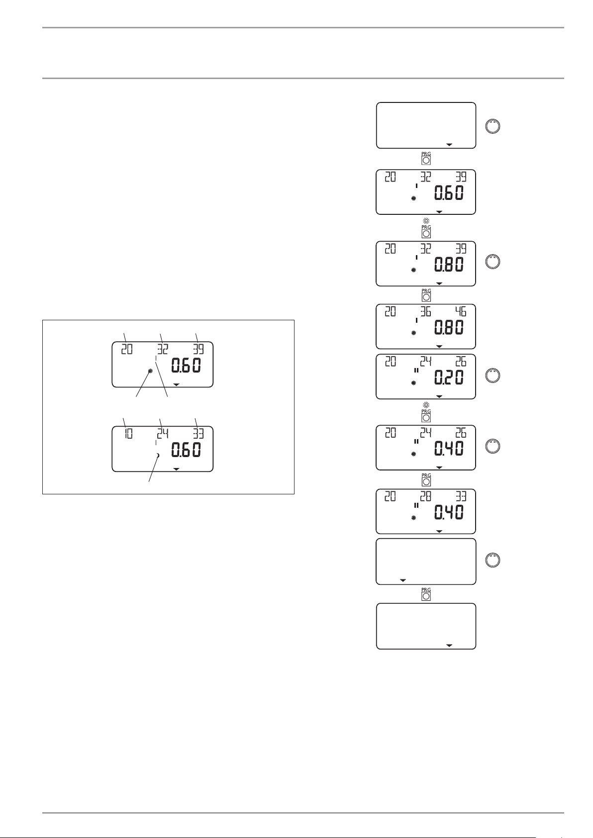
4.5.7 HEATING CURVES
The HTG CURVE menu item enables you to adjust one HTG CURVE
each for heating circuit 1 and 2.
Note: Your contractor will have set up a building and system-specific optimum heating curve for every heating circuit. It relates to
the heat pump return temperature for heating circuit 1 and to the
mixer flow temperature for heating circuit 2.
When adjusting the heating curve on the heat pump manager, the
calculated set return or flow temperature, which is subject to the
outside temperature and the set room temperature, will be shown
at the top of the display.
As soon as a temperature has been preselected via the fixed temperature parameter at control level 3, heating circuit 1 will be
hidden, and the display will show FIXED VALUE with the relevant
temperature.
Adjusting the heating curve
1 32
HEATING CURVES
4
1 32
1 Relative to an outside temperature of +20 °C
2 Relative to an outside temperature of 0 °C
3 Relative to an outside temperature of -20 °C
4 Day mode
5 Heating circuit 1
6 Setback mode
5
6
C26�03�01�1068
BACK
HEATING CURVES
www.stiebel-eltron.com WPF basic | 13
OPERATION
Operation
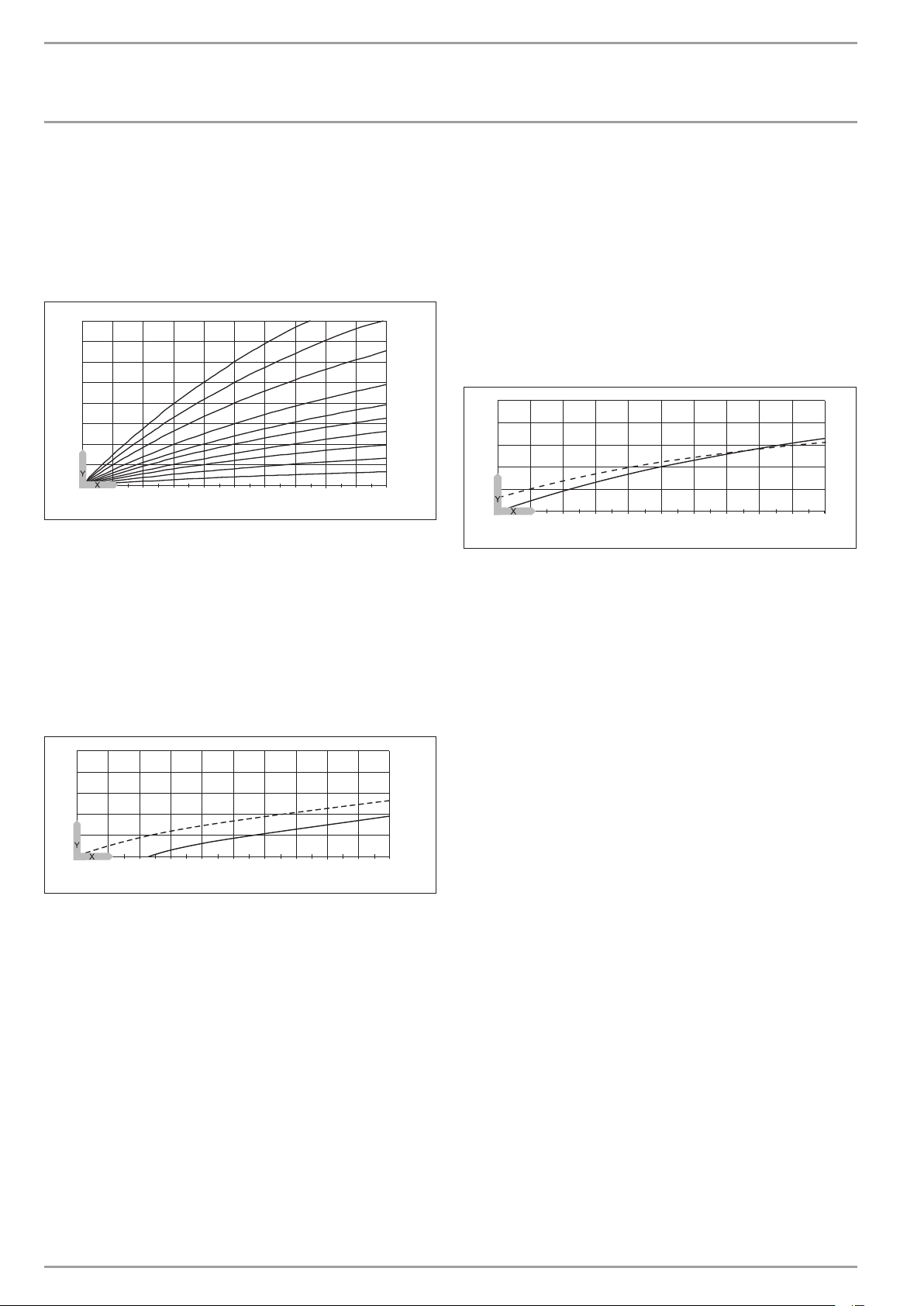
Heating curve diagram
One heating curve can be adjusted for heating circuit 1 and heating
circuit 2 respectively.
At the factory, heating curve 0.6 is set up for heating circuit 1 and
heating curve 0.2 for heating circuit 2.
These heating curves relate to a set room temperature of 20 °C.
-14
-16
-18
2,53
2
1,5
1,2
1
0,8
0,6
0,4
0,2
-20
100
80
60
40
20
2018161412
86420
10
-2-4-6
-8
-10
-12
Y Heating circuit 1, heat pump return temperature [°C]
Heating circuit 2, heat pump flow temperature [°C]
X Outside temperature [°C]
Adjustment of programmed changeover between day and
setback mode
The figure shows a standard heating curve with a slope of 0.8, relative to a set room temperature for day mode of 20°C. The bottom
curve is setback mode. The set room temperature is reduced to 15
°C for setback mode. The heating curve is shifted down parallel
to the original curve.
Adapting a heating curve
Example:
During spring and autumn, the temperature of a building’s heating
system is too low at an outside temperature between 5 °C and
15°C, despite open radiator valves, but is OK at outside temperatures of ≤ 0 °C. This problem can be remedied with a parallel offset
and a simultaneous reduction of the heating curve.
Prior to this adjustment, heating curve 1.0 was adjusted, relative
to a set room temperature of 20 °C. The dotted line indicates the
modified heating curve at 0.83 and a modified set room temperature at 23.2 °C.
70
60
50
40
30
26�03�01�1300
20
2018161412
86420
10
-2-4-6
-8
-10
-12
-14
Y Return/flow temperature [°C]
X Outside temperature [°C]
-16
-18
-20
26�03�01�1302
70
60
50
40
30
20
2018161412
86420
10
Y Return/flow temperature [°C]
X Outside temperature [°C]
1 Day mode
2 Setback mode
-2-4-6
1
2
-8
-10
-12
-14
-16
-18
-20
26�03 �01�1301
14 | WPF basic www.stiebel-eltron.com
OPERATION
Operation
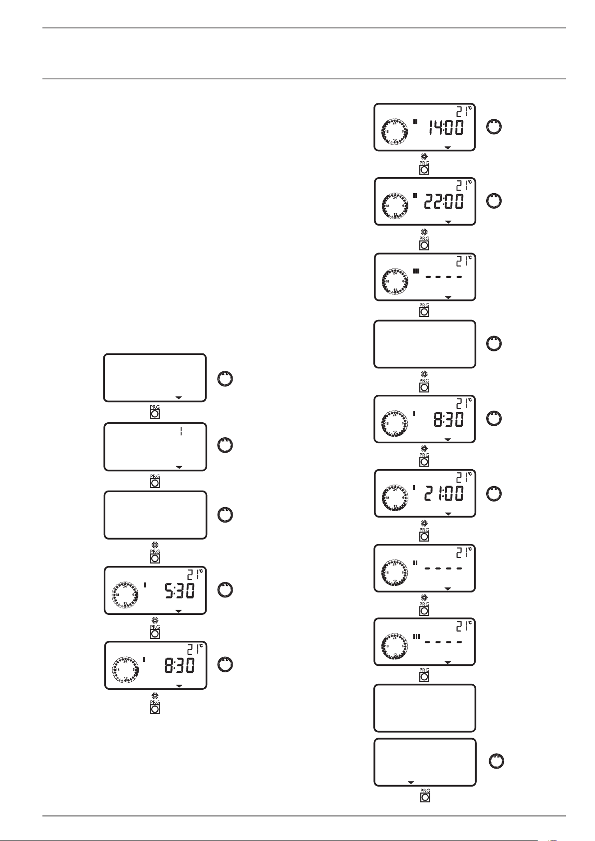
4.5.8 HEATING PROG
The HEATING PROG parameter enables you to determine when and
how often the appliance heats to the set day values for heating
circuit 1 and 2. At all other times, the appliance heats to the set
night temperature. You will have already selected the set values
under menu item ROOM TEMP HC1/2.
You can adjust your heating system as follows:
- for each individual day of the week (Monday, ..., Sunday)
- Monday to Friday (Mo – Fr)
- Saturday and Sunday (Sa – Su)
- the whole week (Mo – Su)
You can adjust three switching time pairs (I, II, III) for each of
these options.
Example:
For heating circuit 1, your heating system should provide heat
daily from Monday to Friday at two different times, i.e. from 05:30
h until 08:30 h as well as from 14:00 h until 22:00 h. For the
weekend, your heating system should provide heat from 08:30 h
until 21:00 h.
HEATING PROG
HEATING START
HEATING STOP
HEATING START
SAT–SUN
HEATING CIRC
MON–FRI
HEATING START
HEATING STOP
HEATING START
HEATING STOP
HEATING START
HEATING START
SAT–SUN
BACK
www.stiebel-eltron.com WPF basic | 15
OPERATION
Operation
BACK
HEATING PROG
DHW START
DHW STOP
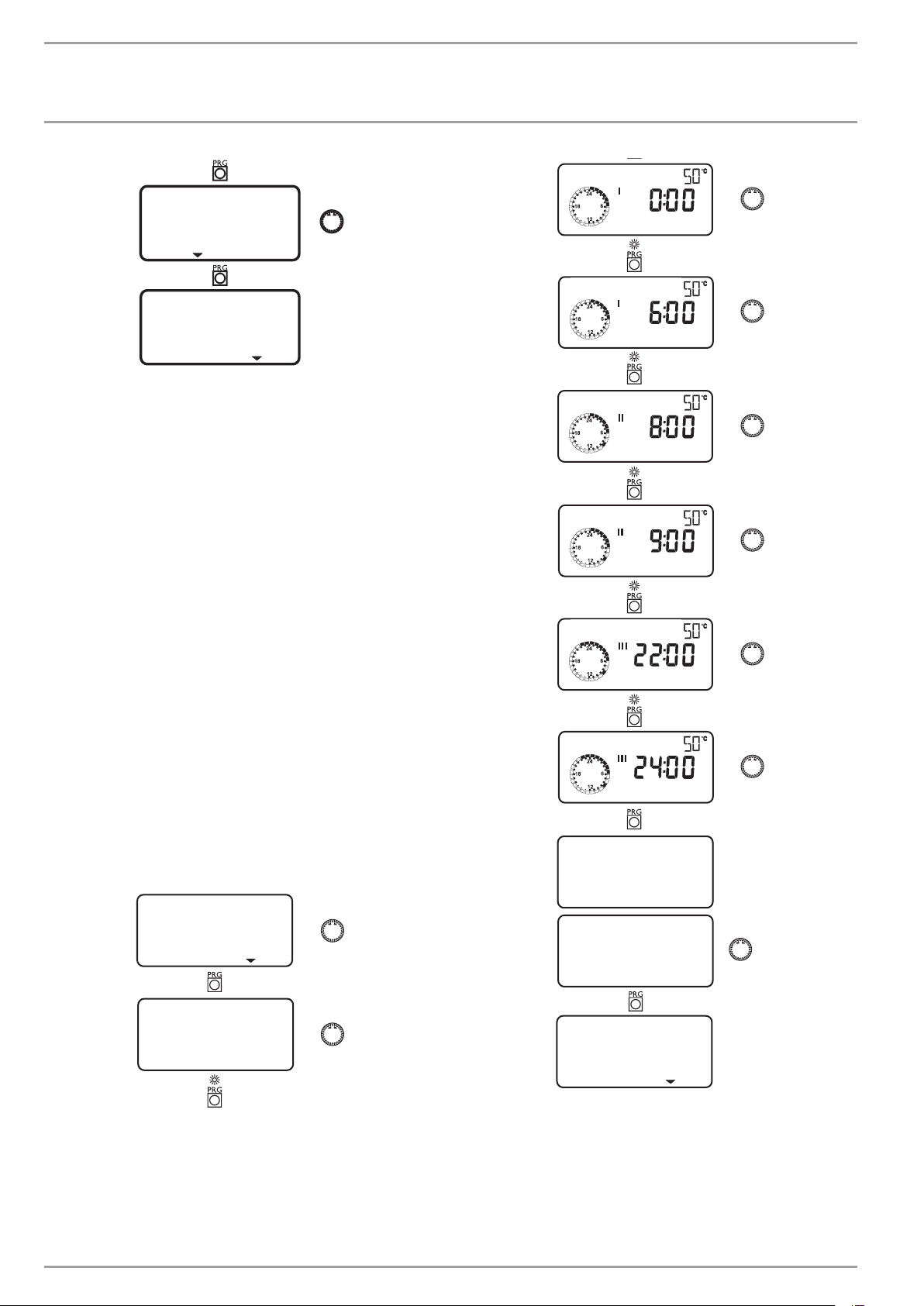
4.5.9 DHW programs
The DHW PROGRAM parameter enables you to select the times
when the appliance will control DHW heating using the set day
value. At all other times, the appliance controls DHW heating using
the set night value. You will have already selected the set values
under system parameter DHW TEMP. bereits eingestellt.
You can adjust your DHW heating as follows:
- for each individual day of the week (Monday, ..., Sunday)
- Monday to Friday (Mo – Fr)
- Saturday and Sunday (Sa – Su)
- the whole week (Mo – Su)
You can adjust three switching time pairs (I, II, III) for each of
these options.
Exception: You will need two switching time pairs, if you want to
heat DHW from 22:00 h until 06:00 h the following day.
Example:
You want to heat up DHW daily at two different times, i.e. from
22:00 h until 06:00 h the following day, and then from 08:00 h
until 09:00 h.
The day begins at 00:00 h; therefore begin programming for this
example at 00:00 h. The first switching times pair runs from 00:00
until 06:00 h. The second switching time pair runs from 08:00
until 09:00 h. The third switching times pair runs from 22:00 h
until 23:59 h.
DHW START
DHW STOP
DHW START
DHW STOP
MON–SUN
DHW PROGRAM
BACK
MON–SUN
16 | WPF basic www.stiebel-eltron.com
DHW PROGRAM
OPERATION
Maintenance and care
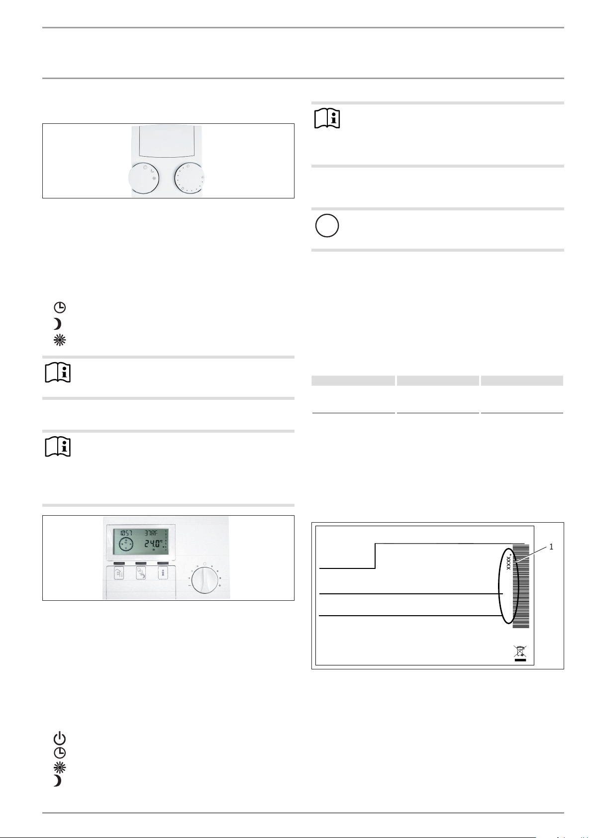
4.6 Remote control FE7
With the FE7 remote control, the following options are available:
- changing the set room temperature for heating for heating
circuit 1 or 2 by ± 5 °C.
- changing the operating mode.
It offers the following controls:
- one rotary selector for changing the set room temperature
- one rotary selector with the following positions
-
Automatic mode
-
Constant setback mode
-
Constant day mode
Note
The remote control is only active when the WPMiw is in
automatic mode.
4.7 Remote control FEK
Note
The parameters heating curve, room temperature and
heating program are not shown at the WPMiw heat pump
manager if the FEK is pre-selected for a specific heating
circuit.
5. Maintenance and care
PIC00000609
Appliance and system damage
!
Maintenance work, such as checking the electrical safety,
must only be carried out by a qualified contractor.
A damp cloth is sufficient for cleaning all plastic and sheet steel
parts. Never use abrasive or corrosive cleaning agents.
Protect the appliance from dust and dirt ingress during building
work.
We recommend a regular inspection (to establish the current condition of the system), and maintenance by a qualified contractor if
required (to return the system to its original condition).
6. Troubleshooting
Fault Cause Remedy
There is no hot water or
the heating system stays
cold.
The fuse/MCB has blown/
has responded.
Check the fuse/MCB in
your fuse box/distribution panel.
Note
In cooling mode, the WPF requires the FEK for area cooling systems, e.g. underfloor heating systems, chilled
ceilings, etc. Apart from the room temperature, it also
determines the dew point temperature to prevent condensation.
With the FEK remote control, the following options are available:
- changing the set room temperature for heating for heating
circuit 1 or 2 by ± 5 °C.
- changing the operating mode.
It offers the following controls:
- one rotary selector for changing the set room temperature
- one “Away” button
- one “Info” button
- one key to select the following operating modes:
-
Standby mode
-
Automatic mode
-
Constant day mode
-
Constant setback mode
6.1 Other problems
If you cannot remedy the fault, notify your heating contractor. To
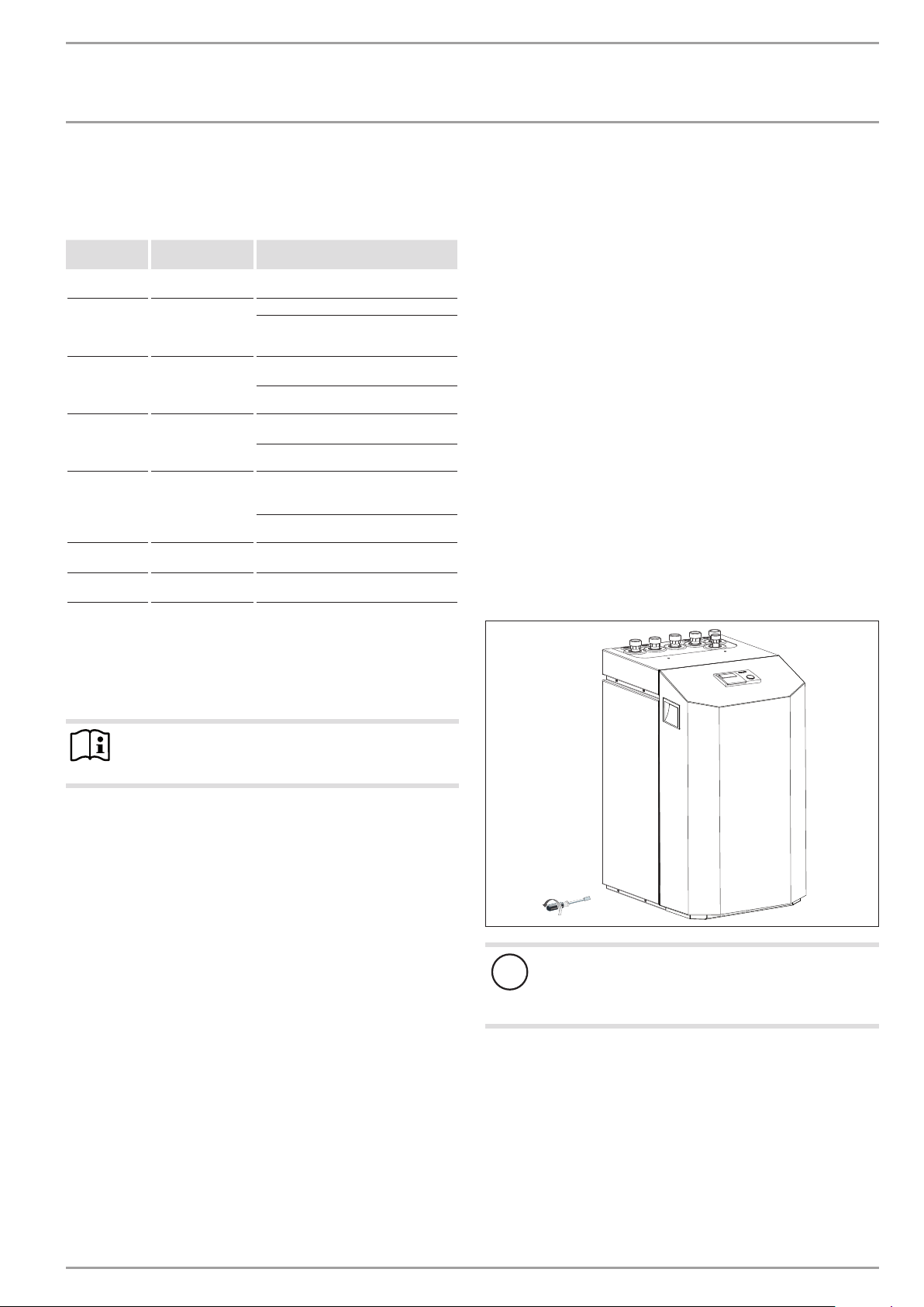
facilitate and speed up your enquiry, please provide the serial
number from the type plate. The type plate is located on the front
at the top on the right or left hand side of the casing.
Sample type plate
*xxxxxxxxxxxxxxxxxx*
PIC00000704
Montageanweisung beachten! Dichtheit geprüft!
1 Number on the type plate
Made in Germany
1
26�03�01�1736
www.stiebel-eltron.com WPF basic | 17

INSTALLATION
Safety
INSTALLATION
7. Safety
7.1 General safety information
- Only qualified contractors should carry out installation, commissioning, maintenance and repair of the appliance.
- We guarantee trouble-free operation and operational reliability only if the original accessories and spare parts intended for the appliance are used.
7.2 Instructions, standards and regulations
Note
Observe all applicable national and regional regulations
and instructions.
7.2.1 Electrical installation
Appliance damage
!
The specified voltage must match the mains voltage. Observe the type plate.
WARNING electrocution
Carry out all electrical connection and installation work
in accordance with national and regional regulations.
DANGER Electrocution
Before any work, isolate the appliance from the power
supply at the control panel.
WARNING electrocution
Only use a permanent connection to the power supply.
The appliance must be able to be separated from the
power supply by an isolator that disconnects all poles
with at least 3mm contact separation. This requirement
can be met by contactors, isolators, fuses etc.
8. Appliance description
8.2 Standard delivery
Delivered with the appliance:
- 1 outside temperature sensor AFS 2
9. Preparations
9.1 General information
Note
The appliance is designed for internal installation, except
in wet areas.
Never install the appliance directly below or next to
bedrooms.
Protect pipe transitions through walls and ceilings with an-
ti-vibration insulation.
The room in which the appliance is to be installed must meet the
following conditions:
- No risk from frost.
- The room must not be subject to a risk of explosions arising
from dust, gases or vapours.
- When installing the appliance in a boiler room together with
other heating equipment, ensure that the operation of other
heating equipment will not be impaired.
- The volume of the installation room should be at least
13.8m³.
- Load-bearing floor (for the weight of the internal unit, see
chapter „Specification / Data table“).
For installation on floating screeds, make provisions for quiet
heat pump operation.
Isolate the mounting surface around the heat pump by re-
cesses. After completing the installation, seal these recesses
with a water-impervious and sound insulating material, such
as silicone for example.
1 2 3 54
8.1 Mode of operation
Environmental energy is extracted by the heat exchanger on the
heat source side (evaporator). Any energy extracted is transferred,
together with the energy drawn by the compressor drive, to the
heating water by a heat exchanger on the heating water side
(condenser). Subject to the heat load, the heating water can be
heated to +60°C. The DHW is heated via the internal indirect coil
inside the DHW cylinder.
The electric booster heater (internal HS 2) starts if the high pressure sensor or the hot gas limiter responds during DHW heating.
In addition it can cover any residual heat demand, if the heating
system demand exceeds the heat pump output.
18 | WPF basic www.stiebel-eltron.com
1 Concrete base
2 Impact sound insulation
3 Floating screed
4 Floor covering
5 Recess
26�03�01�1466
INSTALLATION
Mounting
9.2 Electrical installation
In accordance with VDE 0298-4, use the following cable cross-sections subject to their fuse protection:
Fuse/MCB
rating
C 16 A Compressor
B 16 A
C 16 A
C 25 A
C 35 A
B 16 A Control circuit fuse
C 16 A Control circuit fuse
The electrical data is given in the “Specification” chapter.
Provide separate fuses for the two power circuits of the appliance
and the control unit.
Assignment Cable cross-section
(three phase)
Electric emergency/
booster heater (BH)
(three phase)
Compressor
WPF 5 S basic
(single phase)
Compressor
WPF 7 S basic /
WPF 10 S basic
(single phase)
Electric emergency/
booster heater (BH)
(single phase)
(three phase)
(single phase)
2.5 mm²
2.5 mm²
1.5 mm² with only two live cores and
routing on a wall or in an electrical conduit on a wall.
1.5 mm² for open routing. Note the type
of routing!
2.5 mm² for routing through a
wall. Note the type of routing!
4.0 mm² for open routing. Note the type
of routing!
6.0 mm² for routing through a
wall. Note the type of routing!
4.0 mm² when routing a multi core line
on a wall or in an electrical conduit on
a wall.
6.0 mm² for routing through a
wall. Note the type of routing!
1.5 mm²
1.5 mm²
10. Mounting
10.1 Handling
Transport the appliance in its packaging to protect it against
damage.
Protect the appliance against heavy impact during transport.
- Only allow the appliance to be tilted during transport for a
short time to one of its longitudinal sides.
The longer the appliance is tilted, the greater the distribution
of refrigerant oil in the system.
- Storage and transport at temperatures below - 20 °C and in
excess of + 50 °C are not permissible.
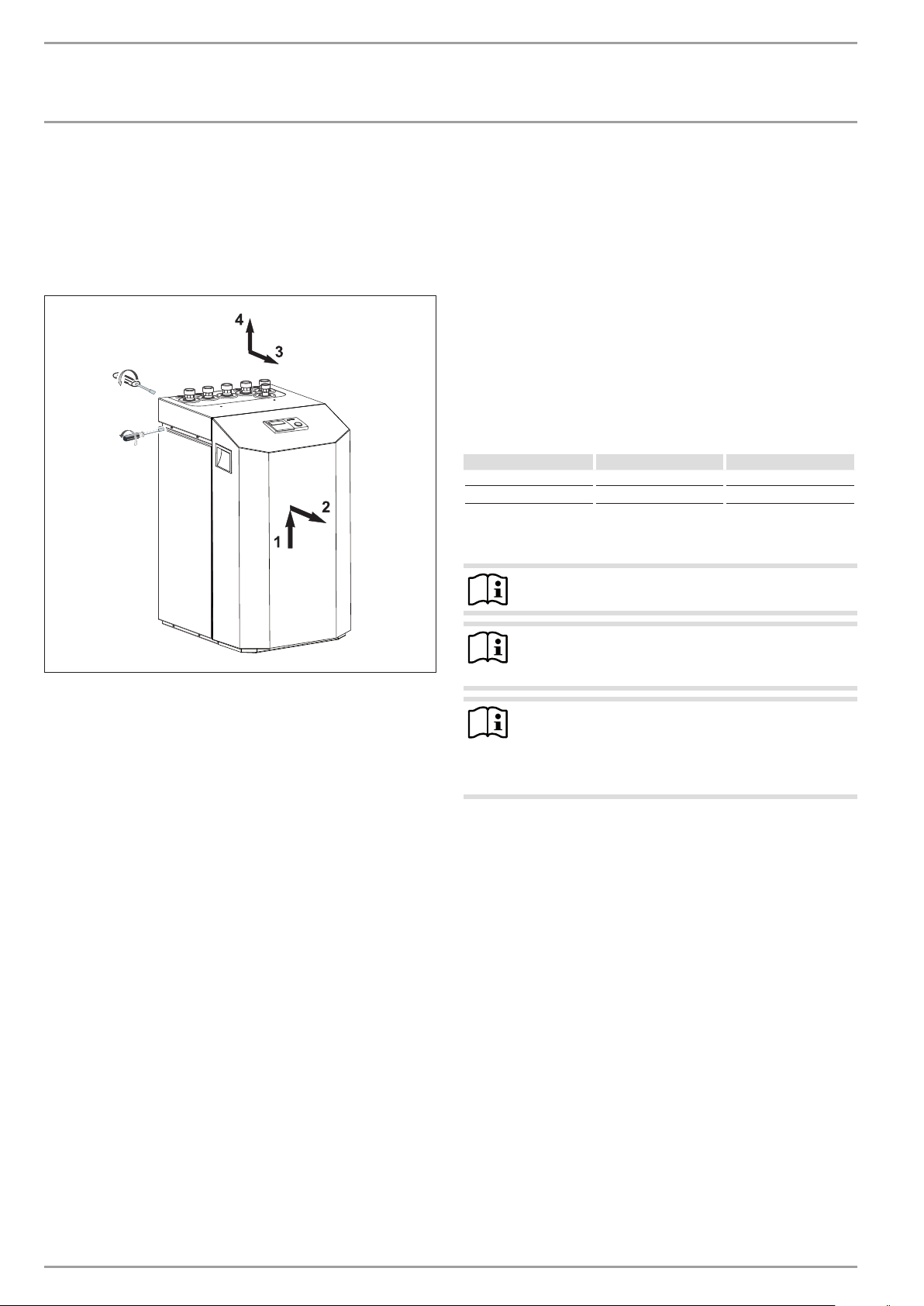
10.2 Positioning
Remove the packaging film and the top and side EPS
padding.
Tilt the appliance backwards slightly and remove it from the
pallet.
Position the appliance on the prepared substrate.
Observe the minimum clearances (see chapter “Dimensions
and connection”).
Remove the six screws from the appliance plinth, and set
down the casing onto the floor.
9.3 Buffer cylinder
Note
In combination with the WPF 13 basic and the WPF 16
basic, it is absolutely imperative to use a buffer cylinder.
A buffer cylinder is recommended to ensure trouble-free appliance
operation.
The buffer cylinder provides hydraulic separation of the flow rates
in the heat pump circuit and the heating circuit.
When operating without a buffer cylinder, observe the details
specified in the chapter “Minimum flow rate without buffer
cylinder”.
6x
Appliance damage
!
The casing must stand on the floor free from the refrigeration unit. D. h. That means, the six plinth screws must
not be refitted.
26�03�01�1573
www.stiebel-eltron.com WPF basic | 19
INSTALLATION
Mounting
10.3 Removing the casing panels
When removing the front cover ensure, that the cables, which
connect the heat pump manager with the control panel, are not
torn off.
The same applies to the earth connection which electrically connects the front cover to the casing.
2x
4x
10.4.3 Connection and filling with brine
Prior to connecting the heat pump, check the heat source circuit
for possible leaks, and flush thoroughly.
Calculate the volume of the heat source circuit. The brine volume
of the heat pump under operating conditions can be found in the
data table (see chapter “Specification”).
The overall volume is equal to the required amount of brine made
by mixing undiluted ethylene glycol and water. The chloride content of the water must not exceed 300 ppm.
Mixing ratio
The brine concentration varies when using a ground collector or
a geothermal probe as a heat source.
The mixing ratio can be found in the table below.
Ethylene glycol Water
Geothermal probe 25 % 75 %
Geothermal collector 33 % 67 %
Charging the brine circuit
Note
The WPF S series does not have a brine pressure switch.
10.4 Installing the heat source system
Design the heat source system for the ground source heat pump
in accordance with the technical guides.
10.4.1 Permitted brine:
- Heat transfer medium as concentrate on an ethylene glycol
base, part no: 231109
- Heat transfer medium as concentrate on an ethylene glycol
base, part no: 161696
10.4.2 Circulation pump and required flow rate
Use a circulation pump with compound-filled windings to supply
the brine, to prevent an earth short circuit through condensate in
the electrical part of the pump (cold water version).
Size the circulation pump in accordance with the system-specific
conditions, h. i.e. nominal flow rate and pressure drop must be
taken into consideration (see “Specification”).
An adequate flow rate must be safeguarded at every possible
brine temperature, i.e.:
Nominal flow rate at a brine temperature of 0°C with a tolerance
of +10%.
Note
26�03�01�1574
The brine/water heat pump is equipped with a brine pressure
switch in the brine circuit. The brine pressure switch prevents
brine getting into the ground if there is a leak in the brine circuit.
If the pressure in the brine circuit falls below 0.7bar, the brine
pressure switch turns the heat pump off. In order for the heat
pump to be enabled again, the pressure must be raised to at least
1.5bar while the heat pump is on standby.
To prevent the brine pressure switch turning the heat pump off
when there is no leak, charge the heat source side of the heat
pump during installation with a minimum pressure of >1.5bar.
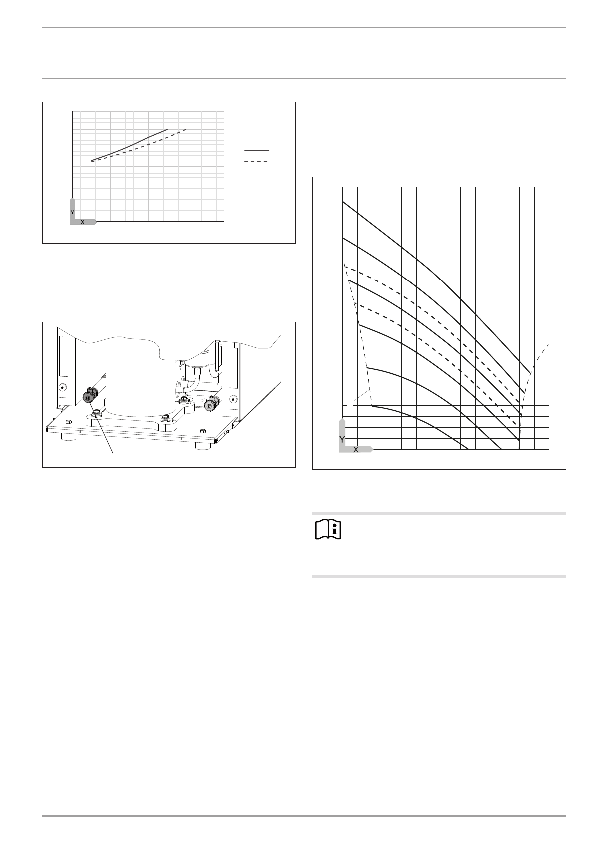
Fill the system according to the following curve.
Insulate the brine lines with diffusion-proof thermal
insulation.
Note
The brine pressure switch is bridged to the power supply
utility contact at the factory.
To activate the brine pressure switch, remove the
jumper.
20 | WPF basic www.stiebel-eltron.com
INSTALLATION
1
2
Mounting
3
2,5
2
1,5
1
0,5
0
0 200 400 600 800
X System volume [l]
Y Charge pressure [bar]
1 Required charge pressure subject to the system volume with
33% brine
2 Required charge pressure depending on system volume with
25% brine
Check the brine concentration:
Determine the density of the ethylene glycol/water mixture,
e.g. with a hydrometer.
Using the actual density and temperature, you can check the current concentration in the diagram.
1,10
1,09
1,08
D0000058692
1,07
1,06
1,05
1,04
1,03
1,02
1,01
50 Vol.-%
40
33
30
25
20
10
1
1 Drain, brine side
Fill the brine circuit via the drain.
After filling the system with brine and prior to commissioning,
open the drain until brine runs out of it. No water must remain in
the pipe run to the drain.
A
1,00
0,99
0,98
26�03�01�1606
-20 0 20 40 60 80 100
0
X Temperature [°C]
Y Density [g/cm³]
A Frost protection [°C]
Note
The quoted details refer to ethylene glycol. These details
will differ slightly (see “Specification”) when using propylene glycol and the heat transfer medium as readymixed solution.
Thermally insulate all brine pipes with vapour-proof material.
To prevent the transmission of noise, connect the heat source
circuit to the heat pump with flexible pressure hoses.
26�03�01�1914
www.stiebel-eltron.com WPF basic | 21

INSTALLATION
Mounting
10.4.4 Checking the heat source flow rate
The heat source flow rate is set via the temperature differential of
the heat source circuit.
Calculate the temperature differential. For this, operate the
appliance in heating mode or DHW mode.
Max. temperature differential of heat source circuit
6
5
4
3
2
1
-5 0 5 10 15 20
Y Max. temperature differential [K]
X Source inlet temperature [°C]
1 Heating flow 35 °C
2 Heating flow 50 °C
Note
You can check the source outlet temperature on the heat
pump manager display under system parameter TEMPERATURES.
1
2
10.5 Heating water connection
The heat pump heating system must be installed by a qualified
contractor in accordance with the water installation drawings that
are part of the technical documents.
Thoroughly flush the pipework before connecting the heat
pump. Foreign bodies, such as welding beads, rust, sand,
sealant, etc. can impair the operational reliability of the heat
pump.
Connect the heat pump on the hot water side. Check for
tightness.
Ensure the correct connection of the heating flow and return.
Provide thermal insulation in accordance with applicable regulations.
For sizing the heating circuit, note the maximum available external
pressure differential.
10.6 Oxygen diffusion
diffusion may lead to corrosion on the steel components of the
heating system (e.g.on the indirect coil of the DHW cylinder, on
buffer cylinders, steel radiators or steel pipes).
In the event of oxygenation, separate the heating system be-
tween the heating circuit and the buffer cylinder.
Material losses
!
The products of corrosion (e.g.rusty sludge) can settle in the heating system components, which may result in a lower output or fault shutdowns due to reduced
cross-sections.
10.7 Filling the heating system
Fill the heating system via the drain.
84�03�01�0017
1
1 Drain, heating side
Water quality
A fill water analysis must be carried out before the system is
filled. This may, for example, be requested from the relevant water
supply utility.
Material losses
!
To avoid damage as a result of scaling, it may be necessary to soften or desalinate the fill water. The fill water
limits specified in chapter "Specification / Data table"
must always be observed.
Recheck these limits 8-12 weeks after commission-
ing and as part of the annual system maintenance.
Note
With a conductivity >1000μS/cm, desalination treatment
is recommended in order to avoid corrosion.
Note
Suitable appliances for water softening and desalinating,
as well as for charging and flushing heating systems, can
be obtained via trade suppliers.
26�03�01�1606
Material losses
!
Avoid open vented heating systems and underfloor heating systems with plastic pipes which are permeable to
oxygen.
Note
If you treat the fill water with inhibitors or additives, the
same limits as for desalination apply.
10.8 Venting the heating system
In underfloor heating systems with plastic pipes that are permeable to oxygen and in open vented heating systems, oxygen
22 | WPF basic www.stiebel-eltron.com
Vent the pipework carefully.