

OPERATION ANd INsTAllATION
BRINE | WATER HEAT PUMPs
» WPf 20
» WPf 27
» WPf 35
» WPf 40
» WPf 52
» WPf 66
» WPf 27 HT

CONTENT
SPECIAL INFORMATION _____________________________________________3
OPERATION __________________________________________________________4
1. General information �����������������������������������������4
1.1 Safety information ����������������������������������������������� 4
1.2 Other symbols in this documentation ����������������������� 4
1.3 Units of measurement ������������������������������������������ 4
1.4 Heat pump output data ����������������������������������������� 4
2. Safety ���������������������������������������������������������� 4
2.1 Correct use �������������������������������������������������������� 4
2.2 Safety instructions ����������������������������������������������� 4
2.3 CE designation ��������������������������������������������������� 4
3. Device description �������������������������������������������5
3.1 Operational characteristics ������������������������������������ 5
3.2 Function ����������������������������������������������������������� 5
4. Control ��������������������������������������������������������5
5. Maintenance and care ���������������������������������������5
6. Other problems �����������������������������������������������5
INSTALLATION _______________________________________________________6
7. Safety ���������������������������������������������������������� 6
7.1 General safety instructions ������������������������������������ 6
7.2 Instructions. standards and regulations �������������������� 6
8. Device description �������������������������������������������6
8.1 WPF 20 | 27 �������������������������������������������������������� 6
8.2 WPF 35 | 40 | 52 | 66 ��������������������������������������������� 7
8.3 WPF 27 HT ��������������������������������������������������������� 7
9. Standard delivery ��������������������������������������������8
9.1 Accessories �������������������������������������������������������� 8
10. Installation ����������������������������������������������������8
10.1 Transport ���������������������������������������������������������� 8
10.2 Positioning �������������������������������������������������������� 8
10.3 Installation of the heat pump system ������������������������ 9
10.4 Installation of the heat consumer system ������������������ 10
10.5 Fitting the casing parts ���������������������������������������� 12
10.6 Removing the casing parts ����������������������������������� 13
10.7 Power supply ���������������������������������������������������� 14
10.8 Modules ���������������������������������������������������������� 14
11. Commissioning ��������������������������������������������� 16
11.1 Operation and control ����������������������������������������� 16
12. Maintenance ������������������������������������������������ 16
13. Troubleshooting �������������������������������������������� 17
13.1 DIP switch (heat pump) ���������������������������������������� 17
13.2 DIP switch (BA) �������������������������������������������������� 17
13.3 LEDs ________________________________________________________ 17
14. Specification ������������������������������������������������ 18
14.1 Water and brine connection ���������������������������������� 18
14.2 Wiring diagrams for heat pump WPF 20 | 27 �������������� 19
14.3 Wiring diagrams for heat pump WPF WPF 35 | 40 ������� 20
14.4 Wiring diagrams for heat pump WPF WPF 52 | 66 ������� 21
14.5 Wiring diagrams for heat pump WPF WPF 27 HT �������� 22
14.6 Output diagrams WPF 20 �������������������������������������� 24
14.7 Output diagrams WPF 27 �������������������������������������� 26
14.8 Output diagrams WPF 27 HT ���������������������������������� 28
14.9 Output diagrams WPF 35 �������������������������������������� 30
14.10 Output diagrams WPF 40 �������������������������������������� 32
14.11 Output diagrams WPF 52 �������������������������������������� 34
14.12 Output diagrams WPF 66 �������������������������������������� 36
14.13 Data table �������������������������������������������������������� 38
WARRANTY
ENVIRONMENT AND RECYCLING _________________________________ 43
2 | WPF 20/27/40/52/66 WWW.STIEBEL-ELTRON.COM

SPECIAL INFORMATION
SPECIAL INFORMATION
- The appliance may be used by children aged8
and up and persons with reduced physical,
sensory or mental capabilities or a lack of
experience and know-how, provided that they are
supervised or they have been instructed on how
to use the appliance safely and have understood
the resulting risks. Children must never play with
the appliance. Children must never clean the
appliance or perform user maintenance unless
they are supervised.
- Use a permanent connection to the power supply.
Ensure the appliance can be separated from the
power supply by an isolator that disconnects all
poles with at least 3mm contact separation.
- Maintain the minimum clearances to ensure
trouble-free operation of the appliance and
facilitate maintenance work.
- At the WPM II. set parameter source in the
commissioning list to "Ethylene glycol". otherwise
the frost stat would stop the heat pump at
temperatures below 7 °C.
- Maintenance work, such as checking the electrical
safety, must only be carried out by a qualified
contractor.
- We recommend an annual inspection (to establish
the system's current condition), and maintenance
by a qualified contractor if required (to return the
system to the desired condition).
- Never interrupt the power supply, even outside
the heating period. The system's active frost
protection is not guaranteed if the power supply
is interrupted.
- There is no need to shut the system down
in summer. The heat pump manager has an
automatic summer/winter changeover.
WWW.STIEBEL-ELTRON.COM WPF 20/27/40/52/66 | 3
OPERATION
GENERAL INFORMATION | SAFETY
OPERATION
1. General information
The chapter entitled “Operation” is intended for appliance users
and contractors.
The chapter entitled “Installation” is intended for contractors.
Note
Read these instructions carefully before using the
appliance and retain them for future reference.
Pass on the instructions to a new user if required.
1.1 Safety information
1.1.1 Structure of safety information
KEYWORD Type of risk
Here, possible consequences are listed that may result
from non-observation of the safety information.
f Steps to prevent the risk are listed.
1.1.2 Symbols, type of risk
Symbol Type of risk
!
Injury
Electrocution
1.4 Heat pump output data
Information regarding the measuring method and interpretation of the heat pump output data provided in these
operating and installation instructions:
The output data provided in the text and diagrams of these
operating and installation instructions has been calculated
according to the standardised measuring conditions of EN14511.
Please note that these standardised measuring conditions do not
always wholly match the local on-site conditions of the individual
system user. The discrepancy may be significant, depending on
the measuring method selected, i.e. the degree of deviation of
the selected method, from the conditions stipulated in EN14511.
Further factors that may have an influence on the measured values
are the measuring equipment, the system configuration, the age
of the system and the flow rates.
It is only possible to confirm the output data provided in these
operating and installation instructions for a specific heat pump if
the measurement used for test purposes was taken under identical
conditions and parameters, i.e. in accordance with EN14511.
2. Safety
2.1 Correct use
The appliance is designed for central heating within the application
limits given in the specification.
This appliance is designed for domestic use. It can be safely
operated by untrained personnel. The appliance can also be used
in a non-domestic environment, e.g. in a small business, as long
as it is used in the same way.
Any other use beyond that described shall be deemed inappropriate.
Observation of this document is also part of the correct use of
the unit. Any changes or conversions to the appliance void any
warranty.
1.2 Other symbols in this documentation
Symbol
!
Note
Notes are bordered by horizontal lines above and below
the text. General information is identified by the symbol
shown on the left.
f This symbol indicates that you have to do something. The
action you need to take is described step by step.
Damage to the appliance and environment
f Read these texts carefully.
1.3 Units of measurement
Note
All measurements are given in mm unless stated
otherwise.
2.2 Safety instructions
Observe the following safety information and instructions.
The electrical installation and installation of the refrigerant circuit
must only be carried out by a recognised. qualified contractor or
by qualified Stiebel Eltron customer service engineers.
The recognised contractor is responsible for adherence to
all currently applicable instructions during installation and
commissioning.
Operate this device only if it is fully installed and all safety
equipment is fitted.
4 | WPF 20/27/40/52/66 WWW.STIEBEL-ELTRON.COM
!
!
OPERATION
DEVICE DESCRIPTION | CONTROL | MAINTENANCE AND CARE
Danger to life through electrocution!
Never spray the device with water or other liquids.
Risk of damage!
Prior to maintenance work. isolate the device from its
power supply.
DANGER Injury
!
he appliance may be used by children aged 8 and up and
persons with reduced physical, sensory or mental capabilities or
a lack of experience provided that they are supervised or they
have been instructed on how to use the appliance safely and have
understood the resulting risks. Children must never play with the
appliance. Children must never clean the appliance or perform
user maintenance unless they are supervised.
2.3 CE designation
The CE designation shows that the device meets all the essential
requirements:
- Electrical Compatibility Directive (2004/108/EC)
- Low Voltage Directive (2006/95/EC)
- Pressure Equipment Directive (97/23/EC)
The rating plate is located at the back of the heat pump.
5. Maintenance and care
Risk of damage!
Maintenance work. such as checking the electrical
safety. must only be carried out by a qualified electrician.
Protect the equipment from dust and dirt ingress during
building work.
A damp cloth is sufficient for cleaning all plastic and sheet steel
parts. Do not use abrasive or corrosive cleaning agents!
6. Other problems
Check the fuse/circuit breaker in your fuse box. If it has blown/
tripped. replace/reset the fuse/MCB. Notify your local contractor
if the fuse/MCB blows/trips again.
If you cannot remedy the fault, notify your qualified contractor.
To facilitate and speed up your enquiry, please provide the serial
number from the type plate.
Sample type plate
*xxxxxxxxxxxxxxxxxx*
1
3. Device description
3.1 Operational characteristics
The WPF is a heating heat pump designed as brine/water heat
pump. The heat pump extracts energy from the heat source
medium. i.e. brine. at a low temperature level. This extracted
energy is then transferred to the heating water at a higher
level. enriched with the energy drawn by the compressor.
Subject to the heat source temperature. the heating water can be
heated up to a flow temperature of 60 °C.
With heat pump type WPF HT. subject to the heat source
temperature. the heating water can be heated to a flow
temperature of up to 75 °C.
A modular operation is possible with the WPF.
3.2 Function
The heat source medium (brine) enters the heat pump evaporator.
There. heat is extracted from the medium. so it exits the heat
pump at a lower temperature.
The energy made useful through the heat pump is transferred to
the heating water inside the condenser.
Then. the heating water transfers its energy to the heating circuit.
4. Control
The heat pump is exclusively controlled by the heat pump manager
WPM II. Therefore. observe the instructions in the chapter Operation
in the operating and installation instructions of the heat pump
manager WPM II.
Montageanweisung beachten! Dichtheit geprüft!
1 Number on the type plate
Made in Germany
26�03�01�1736
WWW.STIEBEL-ELTRON.COM WPF 20/27/40/52/66 | 5
INSTALLATION
SAFETY | DEVICE DESCRIPTION
INSTALLATION
7. Safety
Only qualified contractors should carry out installation.
commissioning. maintenance and repair of the appliance.
7.1 General safety instructions
We guarantee trouble-free operation and operational reliability
only if the original accessories and spare parts intended for the
appliance are used.
7.2 Instructions. standards and regulations
Observe all applicable national and regional regulations and instructions.
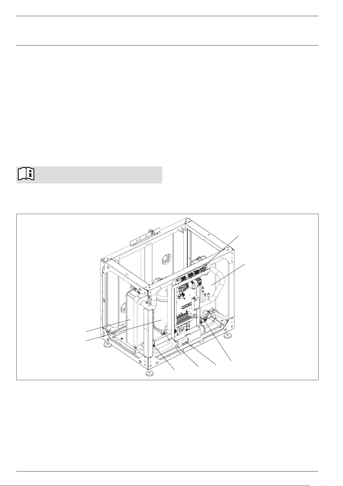
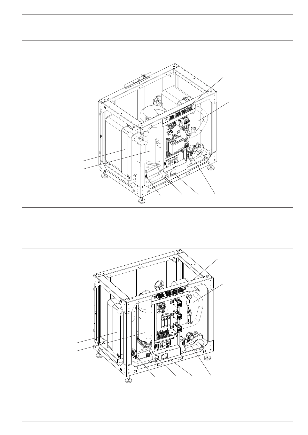
8. Device description
8.1 WPF 20 | 27
8
7
1
2
3
6
1 Electrical terminals
2 Condenser
3 Fill & drain valve (heating)
4 Sight glass
5 Expansion valve
6 Fill & drain valve (brine)
7 Compressor
8 Evaporator
6 | WPF 20/27/40/52/66 WWW.STIEBEL-ELTRON.COM
5
4
26�03�01�1318
INSTALLATION
DEVICE DESCRIPTION
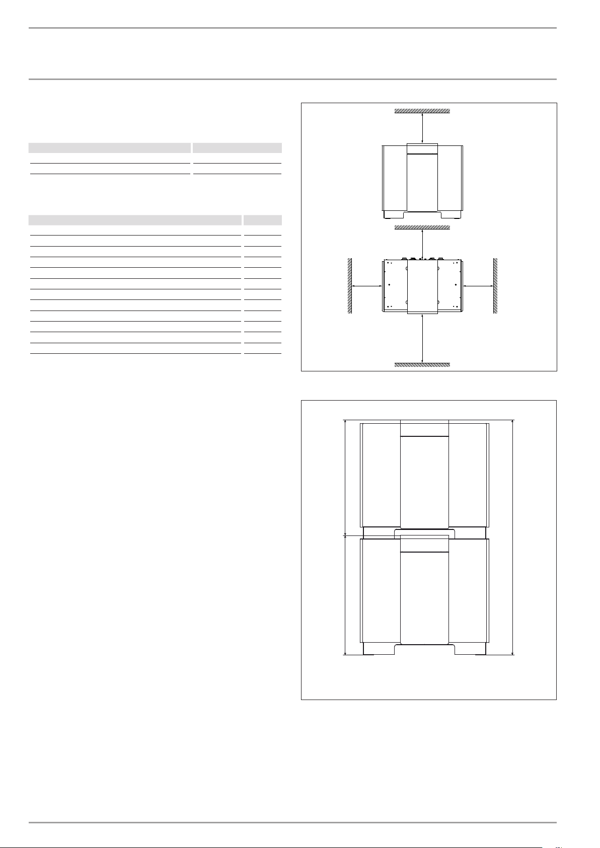
8.2 WPF 35 | 40 | 52 | 66
8
7
1
2
1 Electrical terminals
2 Condenser
3 Fill & drain valve (heating)
4 Sight glass
8.3 WPF 27 HT
8
7
6
5 Expansion valve
6 Fill & drain valve (brine)
7 Compressor
8 Evaporator
5
4
3
26�03�01�0797
1
2
6
1 Electrical terminals
2 Condenser
3 Fill & drain valve (heating)
4 Sight glass
WWW.STIEBEL-ELTRON.COM WPF 20/27/40/52/66 | 7
5
5 Expansion valve
6 Fill & drain valve (brine)
7 Compressor
8 Evaporator
4
3
26�03�01�0797
INSTALLATION
Standard delivery |
INSTALLATION
9. Standard delivery
Heat pumps are delivered in two shipping units.
Designation Part no.
Standard heat pump device
Casing parts 223384
9.1 Accessories
Designation Part no.
Heat pump manager with wall mounting enclosure. WPMW II 185450
Heat pump manager as control panel mounted version. WPMS II 185451
Mixer module with wall mounting enclosure. MSMW 074012
Mixer module as control panel mounted version. MSMS 074011
Cylinder SBP 700 E 185459
Cylinder SBP 700 E SOL 185460
Kit WPVB 227760
Heating system remote control FE 7 185579
Contact sensor AVF 6 165341
Immersion sensor TF 6 165342
Heat transfer medium (concentrate) (10 litre can) 231109
Heat transfer medium (concentrate) (30 litre can) 161696
10. Installation
10.1 Transport
To protect the equipment against damage. transport it vertically
inside its packaging. Storage and transport at temperatures below
– 20 °C and in excess of + 50 °C are not permissible.
In the top of the frame are four holes for fitting lifting eyes M 12
where the equipment can be lifted.
The casing parts are delivered in a separate package. and these
are fitted to the device at the place of installation.
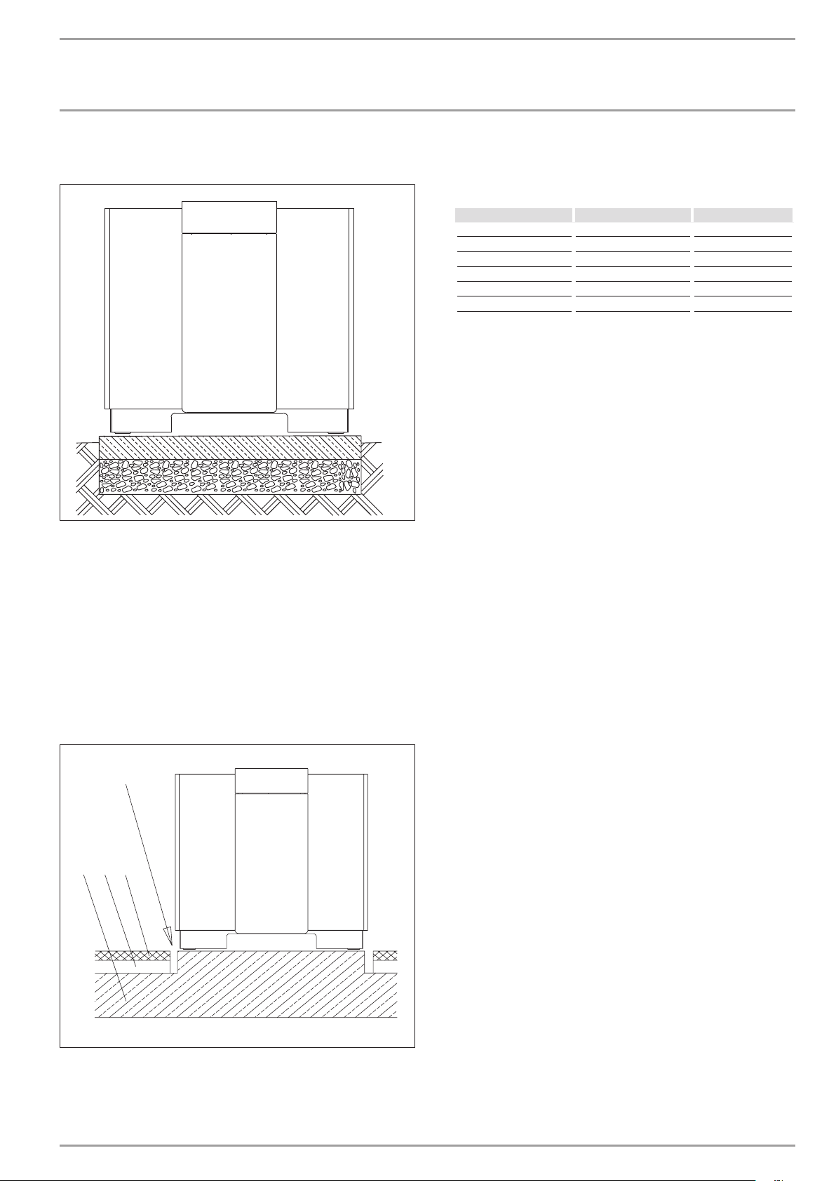
≥500
≥500
≥500
≥1000
2 heat pumps may also be stacked.
f For this, use the WPVB joining set.
≥500
D0000019260
10.2 Positioning
10.2.1 General
Level the device horizontally by adjusting the equipment feet.
To prevent the heat pump from being damaged by frost in case
of external installation. fit and electrically connect the contact
sensor AVF 6 into the heating return as frost protection. Electrical
connection and sensor installation. see chapter "Power supply".
f Observe the minimum clearances.
2269
1154 1115
D0000020355
8 | WPF 20/27/40/52/66 WWW.STIEBEL-ELTRON.COM
INSTALLATION
INSTALLATION
10.2.2 External installation
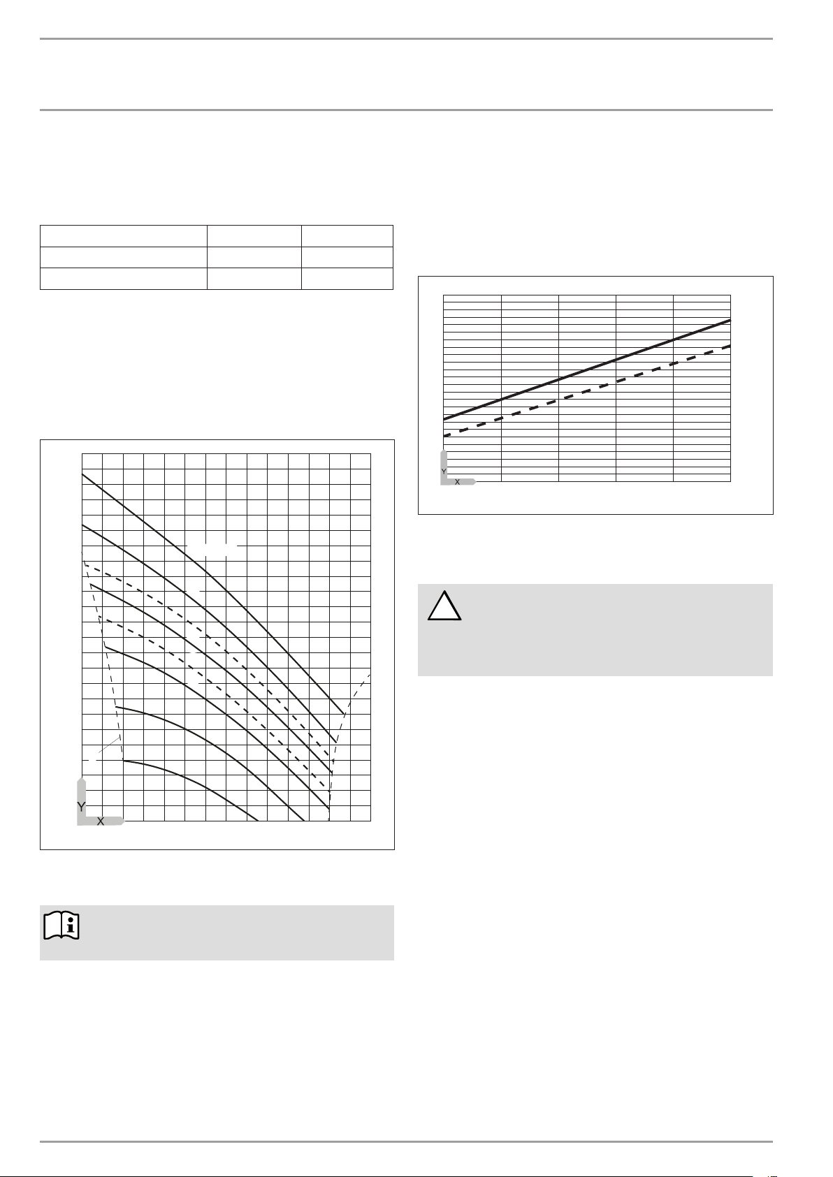
We recommend foundations as base for the device.
Route all supply lines inside a conduit that is free from frost
(protective pipe).
Protect the connection area at the back panel against all weather
and solar influences.
10.2.3 Internal installation
The room where the WPF is to be installed must meet the following
conditions:
- Load-bearing floor. For the weight of the WPF. see
"Specification".
- For a quiet heat pump operation on floating screeds. recess
the screed and the anti-vibration insulation around the
installation location
of the heat pump.
4
1
3
2
- The room must not be subject to a risk of explosions arising
from dust. gases or vapours. Never allow the floor area
and the volume of the installation room to be less than the
minimum values listed in the table.
Typ Volume Floor area
WPF 20 14 m³ 5 m²
WPF 27 | WPF 27 HT 16 m³ 7 m²
WPF 35 23 m³ 9 m²
WPF 40 23 m³ 9 m²
WPF 52 28 m³ 11 m²
WPF 66 33 m³ 13 m²
- When installing the WPF in a boiler room together with
other heating equipment ensure. that the operation of other
heating equipment will not be impaired.
10.2.4 Sound emission.
Never install the heat pump immediately below or adjacent to
bedrooms. Insulate pipes through walls and ceilings against
structure-borne noise transmission.
10.3 Installation of the heat pump system
26�03�01�0803
The layout of the connection material on the soruce side has to
be done according to the evaporator and condensator materials
(Technical Datas) to avoide corrosion.
Design the heat source system for the brine/water heat pump in
accordance with Stiebel Eltron technical guides.
Permitted brine:
- Heat transfer medium as concentrate on an ethylene glycol
base, part no: 231109
- Heat transfer medium as concentrate on an ethylene glycol
base, part no: 161696
10.3.1 Circulation pump and required flow rate
Use a circulation pump with compound-filled windings to supply
the brine. to prevent an earth short circuit through condensation
in the electrical part of the pump (cold water version).
Size the circulation pump in accordance with the system-specific
conditions. i.e. nominal flow rate and pressure drop must be taken
into consideration (see "Specification").
An adequate flow rate must be safeguarded at every possible
brine temperature. i.e.:
Size the nominal flow rate at brine temperature 0 °C with a
tolerance of + 10 %.
10.3.2 Connection and filling with brine
Prior to connecting the heat pump. check the heat source circuit
for possible leaks. and flush thoroughly.
Calculate the volume of the heat source circuit. You can obtain the
brine volume inside the heat pump from the "Specification" table.
The overall volume equals that of the required amount of brine
that should be mixed from undiluted ethylene glycol and water.
The chloride content of the water must not exceed 300 ppm.
C26�03�01�0802
1 Concrete ceiling
2 Impact sound insulation
3 Floating screed
4 Recess
WWW.STIEBEL-ELTRON.COM WPF 20/27/40/52/66 | 9
INSTALLATION
INSTALLATION
Mixing ratio
The brine concentration varies when using a ground collector or
a geothermal probe as a heat source.
The mixing ratio can be found in the table below.
Ethylene glycol Water
Geothermal probe 25% 75%
Geothermal collector 33% 67%
After filling the system with brine and prior to commissioning.
open the fill & drain valve until brine runs out of it. No water must
remain in the pipe run to the fill & drain valve.
10.3.3 Check the brine concentration:
f Determine the density of the ethylene glycol/water mixture,
e.g. with a hydrometer.
Using the actual density and temperature, you can check the actual
concentration in the diagram.
1,10
1,09
1,08
1,07
1,06
1,05
1,04
1,03
1,02
1,01
A
1,00
0,99
0,98
-20 0 20 40 60 80 100
50 Vol.-%
40
33
30
25
20
10
0
X Temperature [°C]
Y Density [g/cm³]
A Frost protection [°C]
Note
The quoted details refer to ethylene glycol (see
"Specification").
10.3.4 Checking the flow rate (during heat pump
commissioning)
Check the flow and return temperatures of the heat source. For
this. determine the temperature differential by measuring the
temperature under the thermal insulation on both flow and return
pipes of the heat pump.
The diagram shows the temperature spread at the nominal flow
rate.
6
5
4
3
2
1
-5 0 5 10 15 20
Y Temperature differential
X Source inlet temperature
1 Brine = heating flow 35 °C
2 Brine = heating flow 50 °C
Risk of damage!
At the WPM II. set parameter source in the commissioning
!
list to "Ethylene glycol". otherwise the frost stat would
stop the heat pump at temperatures below 7 °C. The
source inlet temperature can be checked on the display
of the WPM II under the Info Temp. system parameter.
10.4 Installation of the heat consumer system
The layout of the connection material on the heating side has to
be done according to the evaporator and condensator materials
(Technical Datas) to avoide corrosion.
Implement the heat consumer system (heating circuit) in
accordance with current technical rules. For safety equipment in
heating systems. consult the DIN EN 12828.
Ensure the correct connection of the heating flow and return.
26�03�01�1914
Protect the heating water lines against frost and moisture (only
in case of external installation). Protect flow and return lines
in external installations with an adequate amount of thermal
insulation against frost and by routing them inside a conduit
against moisture
Maintain the required insulation thickness in accordance with the
Heating System Order [or local regulations].
The integral frost protection control (inside the heat pump). that
automatically starts the circulation pump in the heat pump circuit
at + 8 °C and thereby safeguards circulation in all water-bearing
components. offers additional frost protection. The heat pump is
started automatically no later than when the temperature inside
the buffer cylinder drops below + 5 °C.
Prior to connecting the heat pump. check the heating system for
leaks. flush it thoroughly. fill and carefully vent it.
.
1
2
84�03�01�0017
10 | WPF 20/27/40/52/66 WWW.STIEBEL-ELTRON.COM
INSTALLATION
INSTALLATION
10.4.1 Oxygen diffusion
Risk of damage
In underfloor heating systems. avoid open heating
!
systems or the installation of steel pipes in conjunction
with plastic pipes that are permeable to oxygen.
Steel components. such as radiators and pipes. can corrode if
plastic underfloor heating system pipes. which are permeable to
oxygen. are used.
The products of corrosion. e.g. rusty sludge. can settle inside the
heat pump condenser and result in a lower output by reducing
the cross-section. or in a shutdown being activated by the high
pressure limiter.
10.4.2 Filling the heating system
Water quality
A fill water analysis must be available prior to charging the system.
This may, for example, be requested from the relevant water
supply utility.
Material losses
!
To avoid damage as a result of scaling, it may be necessary
to soften or desalinate the fill water. The fill water limits
specified in chapter "Specification / Data table" must
always be observed.
f Recheck these limits 8-12 weeks after
commissioning and as part of annual system
maintenance.
10.4.6 Second external heat source
For dual-mode heating systems. always connect the heat pump
into the return of the second heat source (e.g. oil fired boiler).
High heating water temperature: In dual-mode heating systems.
the return water from the second heat source can flow through
the heat pump. immediately after it has been switched off. with
a max. temperature of 60 °C. The temperature may be 70 °C no
earlier than ten minutes after the heat pump has been shut down.
10.4.7 Heat meter
Observe the additional pressure drop when installing heat meters
on the heating side. The sieves inside the heat meters are easily
blocked by dirt particles in the heating circuit. further increasing
the pressure drop.
Note
With conductivity of >1000μS/cm, desalination treatment
is recommended in order to avoid corrosion.
Note
Suitable appliances for water softening and desalinating,
as well as for charging and flushing heating systems, can
be obtained via trade suppliers.
Note
If you treat the fill water with inhibitors or additives, the
same limits as for desalination apply.
10.4.3 Buffer cylinder
A buffer cylinder is recommended to ensure a trouble-free heat
pump operation. The buffer cylinder provides hydraulic separation
of the volume flow in the heat pump circuit and the heating circuit.
The flow rate in the heat pump remains constant if. for example.
the flow rate in the heating circuit is reduced by thermostatic
valves.
10.4.4 Circulation pump (cylinder primary pump)
When using a buffer cylinder. observe the pressure drop of the
evaporator. of the connecting lines. bends. valves etc. in sizing the
circulation pump to be installed.
10.4.5 Circulation pump (heating circuit pump)
Where no buffer cylinder is used. size the circulation pump
on the heating side taking the condenser pressure drop into
consideration. The flow rate at DT = 10 K (see "Specification") of
the heat pump must be assured under all operating conditions of
the heating system through the installation of an overflow valve.
WWW.STIEBEL-ELTRON.COM WPF 20/27/40/52/66 | 11
INSTALLATION
INSTALLATION
10.5 Fitting the casing parts
Fitting the plinth facia and control panel frame
2
1.
3.2.
1
2
1
C26�03�01�0791
f Hook the plinth facia 1 into the device frame and secure each with three screws
f Position the covers 2 and secure each with two screws to the sides.
Fitting the side covers
1
2
C26�03�01�0792
f Fix the guard plate 1 with four screws. The both in the front with the toothed locked washer.
f Secure the control panel frame 2 with five screws.
12 | WPF 20/27/40/52/66 WWW.STIEBEL-ELTRON.COM
INSTALLATION
INSTALLATION
Fitting the side panels
1
1
2
f Hook the side panels 1 from the top into the slots and hooks
provided and secure with one screw each at the bottom of
the control panel frame.
f Install sound insulation 2 in the control panel frame
Fit front panel
C26�03�01�0793
Fit centre cover
C26�03�01�0794
f Position the cover at the front of the device and push it back;
then secure it with two screws.
f Make the power supply before the centre cover and front
panel are fitted.
C26�03�01�0795
10.6 Removing the casing parts
f Hook the bottom of the front panel into the control panel
frame. pivot it towards the frame and secure with one screw
on each side.
WWW.STIEBEL-ELTRON.COM WPF 20/27/40/52/66 | 13
The casing parts are removed in reverse order.

INSTALLATION
INSTALLATION
10.7 Power supply
Notify your local power supply utility of the electrical connection.
Only qualified electricians must carry out the installation in
accordance with these instructions.
Danger to life through electrocution!
Before any work. isolate the equipment from the power
supply at the control panel.
Observe VDE 0100 [or local regulations] and the regulations of your
local power supply utility.
The heat pump must be able to be separated from the mains power
supply by an additional isolator. that disconnects all poles with at
least 3 mm contact separation. For this purpose. use contactors.
main isolators. fuses. etc. on site.
The terminals are located above the control panel. Remove the lid
to enable the equipment to be connected.
The following are connected at the terminals:
- the power supply of the IWS heat pump control unit
- the compressor power supply
- the brine pump power supply
- the BUS cable (J-Y (St) 2x2x0.8)
Ensure that High. Low and Ground are correctly connected.
- the enable signal for the stand-alone operation at terminal
X4/2. For this. remove the jumper between X4/L and X4/2.
The IWS (integral heat pump controller) is a PCB that is fitted as
standard into the heat pump control panel. The IWS controls the
contactors of the compressors and the starting current limiter.
receives the signal inputs for high pressure. low pressure and
central faults and contains the BUS interface to the WPM II.
Use appropriate cables in accordance with local regulations
for all connections. For this. observe the Electrical details in
"Specification" and the Electrical connection diagram.
Check the strain relief function.
Observe the operating instructions for the WPM II heat pump
manager.
Connect the circulation pump for the heat consumers in accordance
with the electrical connection diagram
documentation.
In case of external installation. use only weather-proof
connecting cables to VDE 0100 [or local regulations]. As a
minimum requirement. use cables with rubber sheathing with
the identification 60245 IEC 57. Route all lines inside a conduit
(protective pipe).
or the engineering
To prevent the heat pump from being damaged by frost in case of
external installation or when installing it in a room that is not free
from the risk of frost. fit and electrically connect the contact sensor
AVF 6 at the heating-return. The contact sensor is electrically
connected at terminals X2/4 and X2/5.
The heating circuit pumps are started when the heating-return
temperature falls to +8 °C. The reverse switching hysteresis is 4 K.
Sensor installation:
f Thoroughly clean the pipe.
f Apply heat conducting paste A.
f Secure the sensor with a tie.
STAND-ALONE operation
In emergencies. this heat pump can also operate without the heat
pump manager (see troubleshooting).
Route all connecting cables and sensor leads through the apertures
in the back panel.
10.8 Modules
When using a modular approach. connect the individual heat
pumps via terminal BUS 1. 2. 3. Ensure that High. Low and Ground
are correctly connected at the WPM II as well as at the heat pump.
14 | WPF 20/27/40/52/66 WWW.STIEBEL-ELTRON.COM

Störung
INSTALLATION
INSTALLATION
Power supply WPF 20. WPF 27. WPF 35, WPF 40. WPF 52. WPF 66. WPF 27 HT
WPM II
BUS / Fühler
X2
X2 LV terminal
1 BUS High H
2 BUS Low L
3 BUS Ground
4 & 5 Temperature sensor B6
X3 Power supply
Heat pump (compressor)
L1. L2. L3. N. PE
X4 Control terminal
Power supply: L. N. PE
Control input:
Ext. control. STAND-ALONE operation
ON. compressor output signal
Fault message. output signal
X5 Power supply
Brine pump
L1. L2. L3. N. PE
~230V 50Hz
X4
3/N/PE
~400V 50Hz
X5
3/N/PE
~400V 50Hz
X3
26�03�01�0796
WWW.STIEBEL-ELTRON.COM WPF 20/27/40/52/66 | 15

!
!
INSTALLATION
COMMISSIONING
| MAINTENANCE
11. Commissioning
Only approved contractors may commission this equipment and
instruct the owner in its use.
Commission the WPF in accordance with these installation
instructions and the operating and installation instructions of the
heat pump manager WPM II. Our customer service can assist in
the commissioning. which is chargeable.
Where this heat pump is used in an installation that is intended
for commercial use. the rules of the relevant Health & Safety at
Work Act may come into play. For further details. check your local
authorising body. The function of the device. including those of
any safety equipment fitted is tested at the factory.
After commissioning. the installer should complete the
commissioning report contained in these instructions.
Check the following prior to commissioning:
Heating system
- Was the heating system filled to the correct pressure. and
was the quick-acting air vent valve opened?
Temperature sensor
- Were the outside temperature and the return temperature
sensor (in conjunction with a buffer cylinder) correctly
positioned and connected?
Power supply
- Was the mains power supply properly connected?
Please note:
!
The compressor in the appliance can only turn in one
direction. If the appliance is not connected correctly. the
compressor remains in operation for 30 seconds then
switches off.
Drain the liquid contained inside the evaporator via the fill & drain
valve that becomes accessible after removing the r.h. side panel.
12. Maintenance
Danger to life through electrocution!
Before any work. isolate the equipment from the power
supply at the control panel.
Risk of damage!
Check the refrigerant circuit of the heat pump WPF 20,
27, 35, 40, 52, 66 annually for tightness in accordance
with EU Directive 842/2006.
Document tightness tests in the service record.
If heat meters are installed. frequently clean their sieves. which
block easily.
When the heat pump operation is impaired (high pressure limiter
responds) through deposits of corrosion by-products (rust sludge)
inside the condenser. only dissolving them by means of solvents
used by our customer service will remove this problem.
Risk of damage!
Never change the factory setting of the rotary selector
on the overcurrent circuit breaker
Factory setting
WPF 52 35 A
WPF 66 45 A
A permanently set overcurrent circuit breaker is installed inside
the compressor of the WPF 20. 27 and 40.
In this case the heat pump manager displays the fault message
"no output". Two phases should then be interchanged to alter the
direction of rotation.
When everything has been implemented correctly. the system
can be heated to its maximum operating temperature and vented
once again.
Risk of damage!
Observe the maximum system temperature in underfloor
!
heating systems.
11.1 Operation and control
A WPM II heat pump manager is required to operate the heat
pump. It regulates the entire heating system. All necessary
adjustments prior and during operation are made on this device.
Only qualified contractors must make adjustments listed in the
commissioning report of the WPM II heat pump manager.
Risk of damage!
The system does not need to be shut down during summer.
!
as the WPM II implements an automatic summer/winter
changeover. If the system is. nevertheless. to be shut
down. set the WPM II to standby. That way the safety
functions that protect the system remain enabled (e.g.
frost protection).
Drain the water side of the equipment. if the heat pump is taken
out of use at a location subject to a risk of frost or if it is installed
externally.
16 | WPF 20/27/40/52/66 WWW.STIEBEL-ELTRON.COM

INSTALLATION
BA
!
TROUBLESHOOTING
13. Troubleshooting
Checking the IWS settings
1
2
1 LEDs
2 DIP switch (BA)
3 Reset button
4 DIP switch (heat pump)
The control panel with the "Internal heat pump controller" (IWS II)
becomes accessible after removing the front hood. The following
list the adjustments of the IWS II required for the WPF:
13.1 DIP switch (heat pump)
The DIP switch (heat pump) enables the pre-selection of the
various compressor systems. Subject to the system heat pump
type. for the WPF this was set to 12 at the factory.
If the WPF is to be operated as a module with another WPF. this
setting (heat pump) remains at 12.
f Please check whether the DIP switch (heat pump) is set
correctly.
3
4
temperature sensor at sensor terminals X2/4 and X2/5. The
sensor must be connected to the heating return (chapter Device
description). The operating mode is indicated by the green LED
on the right.
Risk of damage!
For STAND-ALONE operation. remove the jumper
between X4/1 and X4/2.
13.3 LEDs
Red LED:
The LED flashes when a heat pump fault occurs once. The system
will be shut down.
The red LED illuminates steady if more than 5 heat pump faults
occur within 2 hours. The system will be shut down permanently.
If the red LED is flashing or illuminated steadily, voltage of 230V
is present at the fault output (terminal X4/3).
To delete the faults from the IWS II. select Reset WP and reset
by pressing PRG on the IWS II. The internal counter will then be
26�03�01�0661
returned to zero.
Heat pump faults displayed by the LED: High pressure fault / low
pressure fault. central fault message and hardware faults at the
IWS II (see fault list).
Green centre LED: Flashes during the initialisation and becomes
steady after the BUS address has been allocated. Communication
to the WPM II is only then established. This is only relevant for the
WPF. if the control unit is replaced. otherwise the unit is initialised
at the factory.
Green r.h. LED: Illuminates steady if STAND-ALONE operation has
been selected.
Reset button
In case of incorrect initialisation. see chapter 5.4.1 in the operating
and installation instructions of the WPM II.
The correct position of the slide switch can also be checked on
control level 3 on the WPM II. The display should indicate a C under
parameter "Type IWS".
13.2 DIP switch (BA)
Switches 1, 2 and 3 have no relevance to the WPF.
Position switch 4
Switch ON : STAND-ALONE operation
STAND-ALONE operation is only possible if a heat pump type has
been allocated to the WPM II under parameter IWS TYPE.
Should the WPM II heat pump manager develop a fault. the heat
pump can be operated in STAND-ALONE mode in an emergency.
In this operating mode. there is no communication with the WPM
II. The heat pump regulates to a fixed temperature: it starts up at
50 °C and shuts down at 55 °C. For this. 230 V must be applied to
terminal X4/2. and a contact sensor AVF 6 connected as a return
WWW.STIEBEL-ELTRON.COM WPF 20/27/40/52/66 | 17

f01
INSTALLATION
SPECIFICATION
14. Specification
14.1 Water and brine connection
e01
860
b01
1150
1250
WPF 20 WPF 27 WPF 35 WPF 40 WPF 52 WPF 66 WPF 27 HT
b01 Entry electrical cables
e01 Heating flow Male thread G 2 G 2 G 2 G 2 G 2 G 2 G 2
e02 Heating return Male thread G 2 G 2 G 2 G 2 G 2 G 2 G 2
f01 Heat source flow Male thread G 2 G 2 G 2 G 2 G 2 G 2 G 2
f02 Heat source return Male thread G 2 G 2 G 2 G 2 G 2 G 2 G 2
e02
900
772
f02
340
470
360
480
600
720
D0000016833.ai
18 | WPF 20/27/40/52/66 WWW.STIEBEL-ELTRON.COM

8
X2
K1
A2
A1
6
7
Q1
2
1
6
5
4
3
L
1 1
2
1
s u B
Hei ß gas
12
10
9
8
7
H
Einfrierschutz
3
HD/ND
Solepumpe
N
5
4
3
2
1
3
4
5
L
M1
M
3
X3
X5
A2
9
10
1 1
12
13
X1
F ü r e l h
2
1
L1
L2 L3
N
K4
6
4
2
1 3 5
K1
6
4
2
1 3 5
14
L
N
X4
euetS.txE
r .
1/N /PE AC 50Hz 230V
F2
> p
2
3/N/PE AC 50Hz 400V
3/N/PE AC 50Hz 400V
3 2 1
4
5
X23
X34
N3
X23
X29
X33
X30
2 1
1
X24
X24
C
T1
S
T2
R
T3
L1
L2 L3
N
K4
A1
A2
Q1
A2
A1
Q1
2
4
6
5
3
1
L3
L2
L1
T1
T2
T3
A1
A2
T <
E2
1
2
3
Anschluss Solepumpe
L
H
Kleinspannung
BUS
B6
B6
N O
F9
Z2
6
4
2
1 3 5
br ws sw
br ws sw
3
4
5
2
1
X35
6
P
I
P
I
P3
P1
1
1
2
2
12-18V
X28
B5
3
rungötS
INSTALLATION
SPECIFICATION
14.2 Wiring diagrams for heat pump WPF 20 | 27
heater
X24 Power supply earth screw
X28 Plug-in connector terminal strip
X29 Plug-in connector IWS II 12-PIN
X30 Plug-in connector IWS II 3-PIN
X33 Plug-in connector IWS II 5-PIN
X34 Plug-in connector terminal strip - oil sump
X35 Plug-in connector IWS II 6-PIN
Z2 Supressor elemen
WWW.STIEBEL-ELTRON.COM WPF 20/27/40/52/66 | 19
N3 Temp. controller - oil sump heater
P1 High pressure transducer
P3 Low pressure transducer
Q1 Softstart contactor
X1 Terminals
X2 LV terminal
X3 Heat pump - mains
X4 Control voltage terminals
X5 Brine pump terminals
X23 Power supply earth terminal block
not free from the risk of frost)
26�03�01�0853�d
A2 Integral heat pump controller IWS II
B5 Hot gas temperature sensor
B6 Frost sensor (only for ext. inst. or inst. in a room
E2 Oil sump heater
F2 High pressure limiter
F9 Solar pump MCB
K1 Safety contactor
K4 Brine pump contactor
M1 Compressor motor

INSTALLATION
SPECIFICATION
14.3 Wiring diagrams for heat pump WPF WPF 35 | 40
X23
N
L2 L3
3/N/PE AC 50Hz 400V
L1
X3
N
L2 L3
3/N/PE AC 50Hz 400V
L1
Anschluss Solepumpe
X5
2
P1
P
I
1
2
P
I
1
P3
1 3 5
1 3 5
br ws sw
1 3 5
X28
K1
F9
Z2
K4
6
4
2
br ws sw
6
4
2
12-18V
6
4
2
1 3 5
K2
2
4
6
L3
5
L2
3
L1
1
Q1
A1
23
A2
24
T3
6
T2
4
T1
2
A2
K2
A1
Drossel
Z1
X24
R
T3
S
T2
M
3
C
T1
M1
4
1
X1
X30 Plug-in connector IWS II 3-PIN
X33 Plug-in connector IWS II 5-PIN
X34 Plug-in connector terminal strip - oil sump heater
X35 Plug-in connector IWS II 6-PIN
Z1 Supressor elemen
Z2 Supressor elemen
B6
5
4
B6
3 2 1
L
BUS
H
Kleinspannung
X2
B5
X35
A2
1
X29
X1
2
1
Z1/schräg links
Z1/schräg rechts
X23
6
4
5
3
2
1
3
A2
4
4
Q1
5
A2
5
A1
6
K4
Q1
6
7
A1
7
8
N
L
2
3
X33
HD/ND
Solepumpe
9
8
9
10
4
5
3
2
10
1 1
Hei ß gas
1 1
12
N3
X34
Einfrierschutz
12
13
14
T <
3
2
1
1
F ü r e l h
X30
A1
2
1
3
H
L
s u B
P1 High pressure transducer
P3 Low pressure transducer
Q1 Softstart contactor
X1 Terminals
X2 LV terminal
X3 Heat pump - mains
X4 Control voltage terminals
X5 Brine pump terminals
X23 Power supply earth terminal block
X24 Power supply earth screw
X28 Plug-in connector terminal strip
X29 Plug-in connector IWS II 12-PIN
K1
A2
F2
X4
1
E2
> p
2
3
2 1
L
N
törungS
e u e t S . t x E r .
N O
1/N /PE AC 50Hz 230V
X24
not free from the risk of frost)
26�03�01�0806�d
A2 Integral heat pump controller IWS II
B5 Hot gas temperature sensor
B6 Frost sensor (only for ext. inst. or inst. in a room
E2 Oil sump heater
F2 High pressure limiter
F9 Solar pump MCB
K1 Safety contactor
K2 Compressor contactor
K4 Brine pump contactor
M1 Compressor motor
N3 Temp. controller - oil sump heater
20 | WPF 20/27/40/52/66 WWW.STIEBEL-ELTRON.COM

8
X2
K1
A2
A1
6
7
Q1
2
1
6
5
4
3
L
1 1
2
1
s u B
Hei ß gas
12
10
9
8
7
H
Einfrierschutz
3
HD/ND
Solepumpe
N
5
4
3
2
1
3
4
5
L
X3
X5
A2
9
10
1 1
12
13
X1
F ü r e l h
2
1
L1
L2 L3
N
K4
6
4
2
1 3 5
K1
6
4
2
1 3 5
14
L
N
X4
euetS.txE r.
1/N /PE AC 50Hz 230V
F2
> p
2
3/N/PE AC 50Hz 400V
3/N/PE AC 50Hz 400V
3 2 1
4
5
X23
X34
N3
X23
X29
X33
X30
21
1
X24
L1
L2 L3
N
K4
A1
A2
Q1
A2
A1
T <
E2
1
2
3
Anschluss Solepumpe
L
H
Kleinspannung
BUS
B6
B6
NO
F9
Z2
6
4
2
1 3 5
br ws sw
br ws sw
3
4
5
2
1
X35
6
P
I
P
I
P3
P1
1
1
2
2
12-18V
X28
B5
M1
M
3
6
4
2
1 3 5
X24
C
T1
S
T2
R
T3
A2
A1
K2
Q1
2
4
6
5
3
1
L3
L2
L1
T1
T2
T3
K2
23
24
A1
A2
X1
1
4
Drossel
Z1
Z1/schräg rechts
Z1/schräg links
F8
5
3
1
2
4
6
T1
T2
F7
> u
M2
M1
3
Störung
INSTALLATION
SPECIFICATION
14.4 Wiring diagrams for heat pump WPF WPF 52 | 66
X30 Plug-in connector IWS II 3-PIN
X33 Plug-in connector IWS II 5-PIN
heater
X34 Plug-in connector terminal strip - oil sump
X35 Plug-in connector IWS II 6-PIN
Z1 Supressor elemen
Z2 Supressor elemen
WWW.STIEBEL-ELTRON.COM WPF 20/27/40/52/66 | 21
N3 Temp. controller - oil sump heater
P1 High pressure transducer
P3 Low pressure transducer
Q1 Softstart contactor
X1 Terminals
X2 LV terminal
X3 Heat pump - mains
X4 Control voltage terminals
X5 Brine pump terminals
26�03�01�0780�c
A2 Integral heat pump controller IWS II
not free from the risk of frost)
B5 Hot gas temperature sensor
B6 Frost sensor (only for ext. inst. or inst. in a room
E2 Oil sump heater
F2 High pressure limiter
F7 Protective motor switch. internal
F8 Protective motor switch. external
F9 Solar pump MCB
X23 Power supply earth terminal block
X24 Power supply earth screw
X28 Plug-in connector terminal strip
X29 Plug-in connector IWS II 12-PIN
K1 Safety contactor
K2 Compressor contactor
K4 Brine pump contactor
M1 Compressor motor

INSTALLATION
8
X2
K1.1
A2
A1
6
7
K2
2
1
6
5
4
3
L
1 1
2
1
s u B
Hei ß gas
12
10
9
8
7
H
Einfrierschutz
3
HD/ND
Solepumpe
N
5
4
3
2
1
3
4
5
L
X3
X5
A2
9
10
1 1
12
13
X1
F ü r e l h
2
1
L1
L2 L3
N
K4
6
4
2
1 3 5
K1.1
6
4
2
1 3 5
14
L
N
X4
euetS.txE r.
1/N /PE AC 50Hz 230V
F2
> p
2
3/N/PE AC 50Hz 400V
3/N/PE AC 50Hz 400V
3 2 1
4
5
X23
X34
N3
X23
X29
X33
X30
21
1
X24
L1
L2 L3
N
K4
A1
A2
K2
A2
A1
T <
E2
1
2
3
Anschluss Solepumpe
L
H
Kleinspannung
BUS
B6
B6
NO
F9
Z3
6
4
2
1 3 5
sw ws br
sw ws br
3
4
5
2
1
X35
6
P
I
P
I
P3
P1
1
1
2
2
12-18V
X28
B5
M1
M
3
6
4
2
1 3 5
X24
C
T1
S
T2
R
T3
K1
T1
T2
F7
> υ
M2
M1
6
4
2
1 3 5
K2
K1
K1
A2
A1
R1
R2
R3
3
Störung
SPECIFICATION
14.5 Wiring diagrams for heat pump WPF WPF 27 HT
heater
X28 Plug-in connector terminal strip
X29 Plug-in connector IWS II 12-PIN
X30 Plug-in connector IWS II 3-PIN
X33 Plug-in connector IWS II 5-PIN
X34 Plug-in connector terminal strip - oil sump
X35 Plug-in connector IWS II 6-PIN
Z3 Supressor elemen
22 | WPF 20/27/40/52/66 WWW.STIEBEL-ELTRON.COM
N3 Temp. controller - oil sump heater
P1 High pressure transducer
P3 Low pressure transducer
R1 Sart-Resistor
R2 Sart-Resistor
R3 Sart-Resistor
X1 Terminals
X2 LV terminal
X3 Heat pump - mains
X4 Control voltage terminals
X5 Brine pump terminals
X23 Power supply earth terminal block
X24 Power supply earth screw
26�03�01�1435�b
A2 Integral heat pump controller IWS II
room not free from the risk of frost)
B5 Hot gas temperature sensor
B6 Frost sensor (only for ext. inst. or inst. in a
E2 Oil sump heater
F2 High pressure limiter
F7 Protective motor switch. internal
F9 Solar pump MCB
K1 Relay. resitor bridge
K1.1 Safety contactor
K2 Compressor contactor
K4 Brine pump contactor
M1 Compressor motor

INSTALLATION
SPECIFICATION
WWW.STIEBEL-ELTRON.COM WPF 20/27/40/52/66 | 23

INSTALLATION
1
2
3
4
1
2
3
4
SPECIFICATION
14.6 Output diagrams WPF 20
Key to output diagrams
Y Heating output [kW] / power consumption [kW] / coefficient of performance e [-]
X Inlet temperature of the WQA medium [°C]
1 Flow temperature 35 °C
2 Flow temperature 45 °C
3 Flow temperature 55 °C
4 Flow temperature 60 °C
Heating output
37
35
33
31
29
27
25
23
21
19
17
-5 0 5 10 15 20
Power consumption
9,0
8,5
8,0
7,5
7,0
6,5
D0000021913
6,0
5,5
5,0
4,5
4,0
-5 0 5 10 15 20
24 | WPF 20/27/40/52/66 WWW.STIEBEL-ELTRON.COM
D0000021913

1
2
3
4
INSTALLATION
SPECIFICATION
COP
8
7
6
5
4
3
2
1
0
-5 0 5 10 15 20
D0000021913
WWW.STIEBEL-ELTRON.COM WPF 20/27/40/52/66 | 25

INSTALLATION
1
2
3
4
1
2
3
4
SPECIFICATION
14.7 Output diagrams WPF 27
Key to output diagrams
Y Heating output [kW] / power consumption [kW] / coefficient of performance e [-]
X Inlet temperature of the WQA medium [°C]
1 Flow temperature 35 °C
2 Flow temperature 45 °C
3 Flow temperature 55 °C
4 Flow temperature 60 °C
Heating output
53
48
43
38
33
28
23
-5 0 5 10 15 20
Power consumption
12
11
10
9
8
7
D0000021913
6
5
-5 0 5 10 15 20
26 | WPF 20/27/40/52/66 WWW.STIEBEL-ELTRON.COM
D0000021913

1
2
3
4
INSTALLATION
SPECIFICATION
COP
8
7
6
5
4
3
2
1
0
-5 0 5 10 15 20
D0000021913
WWW.STIEBEL-ELTRON.COM WPF 20/27/40/52/66 | 27

INSTALLATION
35
45
55
65
75
35
45
55
65
75
SPECIFICATION
14.8 Output diagrams WPF 27 HT
Key to output diagrams
Y Heating output [kW] / power consumption [kW] / coefficient of performance e [-]
X Inlet temperature of the WQA medium [°C]
1 Flow temperature 35 °C
2 Flow temperature 45 °C
3 Flow temperature 55 °C
4 Flow temperature 60 °C
Heating output
42
37
32
27
22
17
-5 0 5 10 15 20
Power consumption
15
14
13
12
11
10
9
8
D0000021913
7
6
5
-5 0 5 10 15 20
28 | WPF 20/27/40/52/66 WWW.STIEBEL-ELTRON.COM
D0000021913

35
45
55
65
75
INSTALLATION
SPECIFICATION
COP
8
7
6
5
4
3
2
1
0
-5 0 5 10 15 20
D0000021913
WWW.STIEBEL-ELTRON.COM WPF 20/27/40/52/66 | 29

1
2
3
4
1
2
3
4
INSTALLATION
SPECIFICATION
14.9 Output diagrams WPF 35
Key to output diagrams
Y Heating output [kW] / power consumption [kW] / coefficient of performance e [-]
X Inlet temperature of the WQA medium [°C]
1 Flow temperature 35 °C
2 Flow temperature 45 °C
3 Flow temperature 55 °C
4 Flow temperature 60 °C
Heating output
62
57
52
47
42
37
32
27
-5 0 5 10 15 20
Power consumption
16
15
14
13
12
11
D0000021913
10
9
8
7
-5 0 5 10 15 20
30 | WPF 20/27/40/52/66 WWW.STIEBEL-ELTRON.COM
D0000021913

1
2
3
4
INSTALLATION
SPECIFICATION
COP
8
7
6
5
4
3
2
1
0
-5 0 5 10 15 20
D0000021913
WWW.STIEBEL-ELTRON.COM WPF 20/27/40/52/66 | 31

1
2
3
4
1
2
3
4
INSTALLATION
SPECIFICATION
14.10 Output diagrams WPF 40
Key to output diagrams
Y Heating output [kW] / power consumption [kW] / coefficient of performance e [-]
X Inlet temperature of the WQA medium [°C]
1 Flow temperature 35 °C
2 Flow temperature 45 °C
3 Flow temperature 55 °C
4 Flow temperature 60 °C
Heating output
74
69
64
59
54
49
44
39
34
-5 0 5 10 15 20
Power consumption
17
16
15
14
13
12
D0000021913
11
10
9
8
-5 0 5 10 15 20
32 | WPF 20/27/40/52/66 WWW.STIEBEL-ELTRON.COM
D0000021913

1
2
3
4
INSTALLATION
SPECIFICATION
COP
8
7
6
5
4
3
2
1
0
-5 0 5 10 15 20
D0000021913
WWW.STIEBEL-ELTRON.COM WPF 20/27/40/52/66 | 33

1
2
3
4
1
2
3
4
INSTALLATION
SPECIFICATION
14.11 Output diagrams WPF 52
Key to output diagrams
Y Heating output [kW] / power consumption [kW] / coefficient of performance e [-]
X Inlet temperature of the WQA medium [°C]
1 Flow temperature 35 °C
2 Flow temperature 45 °C
3 Flow temperature 55 °C
4 Flow temperature 60 °C
Power consumption
95
90
85
80
75
70
65
60
55
50
45
-5 0 5 10 15 20
Leistungsaufnahme
21
20
19
18
17
16
D0000021913
15
14
13
12
11
-5 0 5 10 15 20
34 | WPF 20/27/40/52/66 WWW.STIEBEL-ELTRON.COM
D0000021913

1
2
3
4
INSTALLATION
SPECIFICATION
COP
8
7
6
5
4
3
2
1
0
-5 0 5 10 15 20
D0000021913
WWW.STIEBEL-ELTRON.COM WPF 20/27/40/52/66 | 35

1
2
3
4
1
2
3
4
INSTALLATION
SPECIFICATION
14.12 Output diagrams WPF 66
Key to output diagrams
Y Heating output [kW] / power consumption [kW] / coefficient of performance e [-]
X Inlet temperature of the WQA medium [°C]
1 Flow temperature 35 °C
2 Flow temperature 45 °C
3 Flow temperature 55 °C
4 Flow temperature 60 °C
Heating output
113
103
93
83
73
63
53
-5 0 5 10 15 20
Power consumption
29
27
25
23
21
D0000021913
19
17
15
13
-5 0 5 10 15 20
36 | WPF 20/27/40/52/66 WWW.STIEBEL-ELTRON.COM
D0000021913

1
2
3
4
INSTALLATION
SPECIFICATION
COP
8
7
6
5
4
3
2
1
0
-5 0 5 10 15 20
D0000021913
WWW.STIEBEL-ELTRON.COM WPF 20/27/40/52/66 | 37

INSTALLATION
SPECIFICATION
14.13 Data table
Output details apply to new appliances with clean heat exchangers.
WPF 20 WPF 27 WPF 27 HT WPF 35 WPF 40 WPF 52 WPF 66
233003 233004 233009 233005 233006 233007 233008
Outputs to EN 14511
Output at B0/W35 (EN 14511) kW 21.5 29.69 27.41 38.04 43.1 55.83 67.10
Power consumptions to EN 14511
Power consumption at B0/W35 (EN 14511) kW 4.61 6.12 6.32 7.96 9.23 11.61 14.71
Coeff icients of performance to EN 14511
Coeff icient of performance at B0/W35 (EN 14511) 4.66 4.85 4.34 4.78 4.67 4.81 4.56
Sound data
Sound power level (EN 12102) dB(A) 54.6 55 55 56 57.9 58 61.5
Sound pressure level at 1 m distance in a free
field
Sound pressure level at 5 m distance in a free
field
Application limits
Min. installation room volume m³ 14 16 24 20 23 27 33
Max. permissible pressure MPa 0.6 0.6 0.6 0.6 0.6 0.6 0.6
Min. application limit on the heating side °C 15 15 15 15 15 15 15
Max. application limit on the heating side °C 60 60 75 60 60 60 60
Heat source application limit (min.) °C -5 -5 -5 -5 -5 -5 -5
Heat source application limit (max.) °C 20 20 20 20 20 20 20
[Wasserhärte] °dH ≤3 ≤3 ≤3 ≤3 ≤3 ≤3 ≤3
[pH-Wert (mit Aluminiumverbindungen)] [mg/l] 8.0-8.5 8.0-8.5 8.0-8.5 8.0-8.5 8.0-8.5 8.0-8.5 8.0-8.5
[pH-Wert (ohne Aluminiumverbindungen)] [mg/l] 8.0-10.0 8.0-10.0 8.0-10.0 8.0-10.0 8.0-10.0 8.0-10.0 8.0-10.0
[Chlorid] [mg/l] <30 <30 <30 <30 <30 <30 <30
[Leitfähigkeit (Enthärten)] [μS/cm] <1000 <1000 <1000 <1000 <1000 <1000 <1000
[Leitfähigkeit (Entsalzen)] [μS/cm] 20-100 20-100 20-100 20-10 0 20-10 0 20 -100 20-100
[Sauerstoff 8-12 Wochen nach Befüllung (Ent-
härten)]
[Sauerstoff 8-12 Wochen nach Befüllung (Ent-
salzen)]
Electrical details
Frequency Hz 50 50 50 50 50 50 50
Control circuit fuse A 1x B 16 1 x B 16 1 x B 16 1 x B 16 1 x B 16 1 x B 16 1 x B 16
Fuse - compressor A 3 x C 35 3 x C 35 3 x C 35 3 x C35 3 x C 35 3 x C 50 3 x C 50
Control phases 1/N/PE 1/N/PE 1/N/PE 1/N/PE 1/N/PE 1/N/PE 1/N/PE
Compressor phases 3/PE 3/PE 3/PE 3/PE 3/PE 3/PE 3/PE
Rated control voltage V 230 230 230 230 230 230 230
Rated compressor voltage V 400 400 400 400 400 400 400
Current (with/without softstarter) A 55/- 60/- 90/- 60/- 60/- 65/- 80/Operating current max. A 15 19 23.3 23.5 30 32 41
Max. phase angle cos(phi) 0.83 0.83 0.82 0.79 0.87 0.88
Versions
Refrigerant R410 A R410 A R134a R410 A R410 A R410 A R410 A
Refrigerant capacity kg 5.99 7.2 5.99 10.0 10 12 14.5
Compressor oil Emkarate RL
Condenser material 1.4401/Cu 1.4401/Cu 1.4401/Cu 1.4401/Cu 1.4401/Cu 1.4401/Cu 1.4401/Cu
Evaporator material 1.4401/Cu 1.4401/Cu 1.4401/Cu 1.4401/Cu 1.4401/Cu 1.4401/Cu 1.4401/Cu
IP-Rating IP34 D IP34 D IP34 D IP34 D IP34 D IP34 D IP34 D
Dimensions
Height mm 1154 1154 1154 1154 1154 1154 1154
Width mm 1242 1242 1242 1242 1242 1242 1242
Depth mm 860 860 860 860 860 860 860
Weights
Weight kg 345 367 409 391 415 539 655
Connections
Connection on the heating system side G 2 G 2 G 2 G 2 G 2 G 2 G 2
Connection on the heat source side G 2 G 2 G 2 G 2 G 2 G 2 G 2
Connecting cable mm
Values
permissible refrigerant pressure MPa 4.3 4.3 2.4 4.3 4.3 4.3 4.3
Brine volume l 11.2 13 13 16.6 16.6 20.2 23.8
dB(A) 47 47 47 48 49.9 50 53.5
dB(A) 33 33 33 34 35.9 36 39.5
[mg/l] <0.02 <0.02 <0.02 <0.02 <0.02 <0.02 <0.02
[mg/l] <0.1 <0.1 <0.1 <0.1 <0.1 <0.1 <0.1
32 3MAF
2
Emkarate RL
32 3MAF
5 x 6.0 5 x 6.0 5 x 6.0 5 x 6.0 5 x 6.0 5 x 10.0 5 x 10.0
Emkarate RL
32 3MAF
Emkarate RL
32 3MAF
Emkarate RL
32 3MAF
Emkarate RL
32 3MAF
Emkarate RL
32 3MAF
38 | WPF 20/27/40/52/66 WWW.STIEBEL-ELTRON.COM

INSTALLATION
SPECIFICATION
WPF 20 WPF 27 WPF 27 HT WPF 35 WPF 40 WPF 52 WPF 66
Pressure differential on the heat source side hPa 150 140 140 160 160 150 160
Pressure differential, central heating side hPa 60 52 52 80 80 60 80
Flow rate, heat source side m³/h 5 7 6.75 8.8 10.5 13 16.1
Rated heating flow rate m³/h 2.65 3.65 3.29 4.48 5.3 6.86 8.26
Heating flow rate (min.) m³/h 1.85 2.56 2.3 3.14 3.71 4.81 5.78
Heating flow rate (EN 14511) at A7/W35, B0/W35
and 5 K
m³/h 3.7 5.12 4.61 6.5 7.42 9.61 11.56
WWW.STIEBEL-ELTRON.COM WPF 20/27/40/52/66 | 39

NOTES
40 | WPF 20/27/40/52/66 WWW.STIEBEL-ELTRON.COM

NOTES
WWW.STIEBEL-ELTRON.COM WPF 20/27/40/52/66 | 41

NOTES
42 | WPF 20/27/40/52/66 WWW.STIEBEL-ELTRON.COM

WARRANTY
ENVIRONMENT AND RECYCLING
Warranty
The warranty conditions of our German companies do not
apply to appliances acquired outside of Germany. In countries
where our subsidiaries sell our products, it is increasingly the
case that warranties can only be issued by those subsidiaries.
Such warranties are only granted if the subsidiary has issued
its own terms of warranty. No other warranty will be granted.
We shall not provide any warranty for appliances acquired in
countries where we have no subsidiary to sell our products.
This will not aect warranties issued by any importers.
Environment and recycling
We would ask you to help protect the environment. After use,
dispose of the various materials in accordance with national
regulations.
KYOTO | R410A
This device is filled with refrigerant R410A.
Refrigerant R410A is a CFC greenhouse gas mentioned in the Kyoto
protocol with a global greenhouse potential (GWP) = 1925.
Never release refrigerant R410A to atmosphere.
WWW.STIEBEL-ELTRON.COM WPF 20/27/40/52/66 | 43

g
y
Deutschland
STIEBEL ELTRON GmbH & Co. KG
Dr.-Stiebel-Straße 33 | 37603 Holzminden
Tel. 05531 702-0 | Fax 05531 702-480
info@stiebel-eltron.de
www.stiebel-eltron.de
Australia
STIEBEL ELTRON Australia Pty. Ltd.
4/8 Rocklea Drive | Port Melbourne VIC 3207
Tel. 03 9645-1833 | Fax 03 9645-4366
info@stiebel.com.au
www.stiebel.com.au
Austria
STIEBEL ELTRON Ges.m.b.H.
Eferdinger Str. 73 | 4600 Wels
Tel. 07242 47367-0 | Fax 07242 47367-42
info@stiebel-eltron.at
www.stiebel-eltron.at
Belgium
STIEBEL ELTRON bvba/sprl
't Hofveld 6 - D1 | 1702 Groot-Bijgaarden
Tel. 02 42322-22 | Fax 02 42322-12
info@stiebel-eltron.be
www.stiebel-eltron.be
China
Stiebel Eltron (Guangzhou) Technology
Development Co., Ltd.
Rm 102, F1, Yingbin-Yihao Mansion, No. 1
Yingbin Road
Panyu District | 511431 Guangzhou
Tel. 020 61952996 | Fax 020 61952990
info@stiebeleltron.cn
www.stiebeleltron.cn
Czech Republic
STIEBEL ELTRON spol. s r.o.
K Hájům 946 | 155 00 Praha 5 - Stodůlky
Tel. 251116-111 | Fax 235512-122
info@stiebel-eltron.cz
www.stiebel-eltron.cz
Denmark
Pettinaroli A/S
Mandal Allé 21 | 5500 Middelfart
Tel. 06341 666-6 | Fax 06341 666-0
info@stiebel-eltron.dk
www.stiebel-eltron.dk
Finland
STIEBEL ELTRON OY
Kapinakuja 1 | 04600 Mäntsälä
Tel. 020 720-9988
info@stiebel-eltron.fi
www.stiebel-eltron.fi
Verkauf Tel. 05531 702-110 | Fax 05531 702-95108 | info-center@stiebel-eltron.de
Kundendienst Tel. 05531 702-111 | Fax 05531 702-95890 | kundendienst@stiebel-eltron.de
Ersatzteilverkauf Tel. 05531 702-120 | Fax 05531 702-95335 | ersatzteile@stiebel-eltron.de
France
STIEBEL ELTRON SAS
7-9, rue des Selliers
B.P 85107 | 57073 Metz-Cédex 3
Tel. 0387 7438-88 | Fax 0387 7468-26
info@stiebel-eltron.fr
www.stiebel-eltron.fr
Hungary
STIEBEL ELTRON Kft.
Gyár u. 2 | 2040 Budaörs
Tel. 01 250-6055 | Fax 01 368-8097
info@stiebel-eltron.hu
www.stiebel-eltron.hu
Japan
NIHON STIEBEL Co. Ltd.
Kowa Kawasaki Nishiguchi Building 8F
66-2 Horikawa-Cho
Saiwai-Ku | 212-0013 Kawasaki
Tel. 044 540-3200 | Fax 044 540-3210
info@nihonstiebel.co.jp
www.nihonstiebel.co.jp
Netherlands
STIEBEL ELTRON Nederland B.V.
Daviottenweg 36 | 5222 BH 's-Hertogenbosch
Tel. 073 623-0000 | Fax 073 623-1141
info@stiebel-eltron.nl
www.stiebel-eltron.nl
Poland
STIEBEL ELTRON Polska Sp. z o.o.
ul. Działkowa 2 | 02-234 Warszawa
Tel. 022 60920-30 | Fax 022 60920-29
stiebel@stiebel-eltron.pl
www.stiebel-eltron.pl
Russia
STIEBEL ELTRON LLC RUSSIA
Urzhumskaya street 4,
building 2 | 129343 Moscow
Tel. 0495 7753889 | Fax 0495 7753887
info@stiebel-eltron.ru
www.stiebel-eltron.ru
Slovakia
TATRAMAT - ohrievače vody, s.r.o.
Hlavná 1 | 058 01 Poprad
Tel. 052 7127-125 | Fax 052 7127-148
info@stiebel-eltron.sk
www.stiebel-eltron.sk
Switzerland
STIEBEL ELTRON AG
Industrie West
Gass 8 | 5242 Lupfig
Tel. 056 4640-500 | Fax 056 4640-501
info@stiebel-eltron.ch
www.stiebel-eltron.ch
Thailand
STIEBEL ELTRON Asia Ltd.
469 Moo 2 Tambol Klong-Jik
Amphur Bangpa-In | 13160 Ayutthaya
Tel. 035 220088 | Fax 035 221188
info@stiebeleltronasia.com
www.stiebeleltronasia.com
United Kingdom and Ireland
STIEBEL ELTRON UK Ltd.
Unit 12 Stadium Court
Stadium Road | CH62 3RP Bromborough
Tel. 0151 346-2300 | Fax 0151 334-2913
info@stiebel-eltron.co.uk
www.stiebel-eltron.co.uk
United States of America
STIEBEL ELTRON, Inc.
17 West Street | 01088 West Hatfield MA
Tel. 0413 247-3380 | Fax 0413 247-3369
info@stiebel-eltron-usa.com
www.stiebel-eltron-usa.com
4<AMHCMN=iaggaj>
Irrtum und technische Änderungen vorbehalten! | Subject to errors and technical changes! | Sous réserve
d‘erreurs et de modifications techniques! | Onder voorbehoud van ver
Salvo error o modificación técnica! | Excepto erro ou alteração técnica | Zastrzeżone zmian
ewentualne błędy | Omyly a technické změny jsou vyhrazeny! | A muszaki változtatások és tévedések jogát
fenntartjuk! |
technické zmeny sú vyhradené! Stand 8870
Отсутствие ошибок не гарантируется. Возможны технические изменения.
issingen en technische wijzigingen! |
techniczne i
| Chyby a
A 280660-37738-8870
B 280643-37738-8870
 Loading...