

STIEBEL ELTRON WPF 5 basic, WPF 7 basic, WPF 5 S basic, WPF 16 basic, WPF 7 S basic Operation And Installation
...Page 1
OPERATION AND INSTALLAT ION
Brine | water heat pumps
» WPF 5 basic
» WPF 7 basic
» WPF 10 basic
» WPF 13 basic
» WPF 16 basic
» WPF 5 S basic
» WPF 7 S basic
» WPF 10 S basic
Page 2

CONTENTS
SPECIAL INFORMATION
OPERATION
1. General information �����������������������������������������3
1.1 Safety instructions ����������������������������������������������� 3
1.2 Other symbols in this documentation ����������������������� 4
1.3 Units of measurement ������������������������������������������ 4
1.4 Standardised output data �������������������������������������� 4
2. Safety ���������������������������������������������������������� 4
2.1 Intended use ������������������������������������������������������ 4
2.2 Safety information ����������������������������������������������� 4
2.3 Test symbols ������������������������������������������������������ 4
3. Appliance description ���������������������������������������4
3.1 Energy saving tip ����������������������������������������������� 5
4. Operation �����������������������������������������������������5
4.1 Operation ���������������������������������������������������������� 6
4.2 Essential facts in brief ������������������������������������������ 6
4.3 Adjustments at control level 1 �������������������������������� 7
4.4 Overview of control level 2������������������������������������� 7
4.5 Adjustments at control level 2 �������������������������������� 8
4.6 Remote control FE7 �������������������������������������������� 17
4.7 Remote control FEK �������������������������������������������� 17
5. Maintenance and care ������������������������������������� 17
6. Troubleshooting �������������������������������������������� 17
6.1 Other problems ������������������������������������������������� 17
INSTALLATION
7. Safety �������������������������������������������������������� 18
7.1 General safety information ����������������������������������� 18
7.2 Instructions, standards and regulations ������������������� 18
8. Appliance description ������������������������������������� 18
8.1 Mode of operation ���������������������������������������������� 18
8.2 Standard delivery ����������������������������������������������� 18
9. Preparations ������������������������������������������������ 18
9.1 General information �������������������������������������������� 18
9.2 Electrical installation������������������������������������������� 19
9.3 Buffer cylinder �������������������������������������������������� 19
10. Mounting ���������������������������������������������������� 19
10.1 Handling ���������������������������������������������������������� 19
10.2 Positioning ������������������������������������������������������� 19
10.3 Removing the casing panels ���������������������������������� 20
10.4 Installing the heat source system ��������������������������� 20
10.5 Heating water connection ������������������������������������� 22
10.6 Oxygen diffusion ������������������������������������������������ 22
10.7 Filling the heating system ������������������������������������ 22
10.8 Venting the heating system ����������������������������������� 22
10.9 Minimum flow rate of heat sink for WPF 5-16 basic ����� 23
10.10 Flow rate of heat sink for WPF 5-10 S basic ��������������� 24
10.11 DHW heating ����������������������������������������������������� 24
10.12 Electrical connection ������������������������������������������� 24
10.13 Fitting the casing parts ���������������������������������������� 28
10.14 installation ������������������������������������������������������� 29
10.15 High limit safety cut-out for underfloor heating
systems STB-FB ������������������������������������������������� 29
10.16 Remote control FE7 �������������������������������������������� 30
10.17 Remote control FEK �������������������������������������������� 30
11. Commissioning ��������������������������������������������� 30
11.1 Checks before commissioning�������������������������������� 30
11.2 Heating curve adjustment during commissioning ������� 31
11.3 Operation and control ����������������������������������������� 31
11.4 Taking the appliance out of use ������������������������������ 31
11.5 Heat pump manager commissioning summary ���������� 32
11.6 Heat pump manager commissioning ����������������������� 34
11.7 WPMiw commissioning report ������������������������������� 41
12. Settings ����������������������������������������������������� 42
12.1 Standard settings ����������������������������������������������� 42
12.2 Heating and DHW programs ����������������������������������42
12.3 Appliance handover �������������������������������������������� 42
13. Troubleshooting �������������������������������������������� 43
13.1 Fault display ����������������������������������������������������� 43
13.2 Resetting the high limit safety cut-out ��������������������� 44
13.3 Fault list parameter �������������������������������������������� 45
14. Maintenance ������������������������������������������������ 45
15. Specification ������������������������������������������������ 46
15.1 Connections ������������������������������������������������������ 46
15.2 Installation dimensions ���������������������������������������� 47
15.3 Wiring diagram WPF 5 basic ��������������������������������� 48
15.4 Wiring diagram WPF 7 basic | WPF 10 basic | WPF 13
basic | WPF 16 basic �������������������������������������������� 50
15.5 Wiring diagram WPF 5-10 S basic ��������������������������� 52
15.6 Output diagrams WPF 5 basic �������������������������������� 54
15.7 Output diagrams WPF 7 basic �������������������������������� 56
15.8 Output diagrams WPF 10 basic ������������������������������58
15.9 Output diagrams WPF 13 basic ������������������������������ 60
15.10 Output diagrams WPF 16 basic ������������������������������ 62
15.11 Output diagrams WPF 5 S basic ������������������������������ 64
15.12 Output diagrams WPF 7 S basic ������������������������������ 65
15.13 Output diagrams WPF 10 S basic ���������������������������� 66
15.14 Data table WPF 5-16 basic ������������������������������������ 67
15.15 Datentabelle WPF 5-10 S basic ������������������������������� 69
15.16 Data table WPMiw ���������������������������������������������� 70
GUARANTEE
ENVIRONMENT AND RECYCLING
2 | WPF basic www.stiebel-eltron.com
Page 3
SPECIAL INFORMATION
General information
SPECIAL INFORMATION
- The appliance may be used by children aged8
and up and persons with reduced physical, sensory or mental capabilities or a lack of experience
and know-how, provided that they are supervised
or they have been instructed on how to use the
appliance safely and have understood the resulting risks. Children must never play with the appliance. Children must never clean the appliance
or perform user maintenance unless they are
supervised.
- Use a permanent connection to the power supply.
Ensure the appliance can be separated from the
power supply by an isolator that disconnects all
poles with at least 3mm contact separation.
- Maintain the minimum clearances to ensure trouble-free operation of the appliance and facilitate
maintenance work.
- The COOLING MODE parameter must only be set if
there is a suitable hydraulic circuit.
- The COOLING MODE parameter will only be
shown if a FEK or FE7 remote control is connected. The cooling mode is only possible in summer.
- Maintenance work, such as checking the electrical safety, must only be carried out by a qualified
contractor.
OPERATION
1. General information
The chapters „Special Information“ and „Operation“ are intended
for both the user and qualified contractors.
The chapter „Installation“ is intended for qualified contractors.
Note
Read these instructions carefully before using the appliance and retain them for future reference.
Pass these instructions on to a new user if required.
1.1 Safety instructions
1.1.1 Structure of safety instructions
KEYWORD Type of risk
Here, possible consequences are listed that may result
from failure to observe the safety instructions.
Steps to prevent the risk are listed.
1.1.2 Symbols, type of risk
Symbol Type of risk
1.1.3 Keywords
Injury
Electrocution
- We recommend a regular inspection (to establish
the current condition of the system), and maintenance by a qualified contractor if required (to
return the system to its original condition).
- Never interrupt the power supply, even outside
the heating period. The system’s active frost protection is not guaranteed if the power supply is
interrupted.
- There is no need to shut the system down in
summer. The heat pump manager has an automatic summer/winter changeover.
KEYWORD Meaning
DANGER Failure to observe this information will result in serious
injury or death.
WARNING Failure to observe this information may result in serious
injury or death.
CAUTION Failure to observe this information may result in non-seri-
ous or minor injury.
www.stiebel-eltron.com WPF basic | 3
Page 4
OPERATION
Safety
1.2 Other symbols in this documentation
Note
General information is identified by the adjacent symbol.
Read these texts carefully.
Symbol Meaning
This symbol indicates that you have to do something. The ac-
tion you need to take is described step by step.
Material losses
(appliance damage, consequential losses and environmental pollution)
Appliance disposal
1.3 Units of measurement
Note
All measurements are given in mm unless stated otherwise.
1.4 Standardised output data
Explanations to determine and interpret the specified standardised
output data
1.4.1 Standard: EN 14511
The output data specifically mentioned in text, diagrams and
technical datasheets has been determined in line with the test
conditions described in the standard shown in the heading of
this chapter.
Generally, these standardised test conditions will not fully meet
the conditions found at the installation site of the system user.
Depending on the chosen test method and the extent to which
the selected method deviates from the conditions described in the
standard shown in the heading of this chapter, any deviations can
have a considerable impact. Further factors that have an influence
on the test values are the measuring equipment, the system configuration, the age of the system and the flow rates.
A confirmation of the specified output data can only be obtained
if the conditions applicable to the relevant test match those of the
standard shown in the heading of this chapter.
2. Safety
2.1 Intended use
The appliance is designed to:
- heat rooms.
- heat DHW.
Observe the operating limits listed in chapter “Specification”.
The appliance is intended for domestic use, i.e. h. it can be used
safely by untrained persons. The appliance can also be used in a
non-domestic environment, e.g. in a small business, as long as it
is used in the same way.
Any other use beyond that described shall be deemed inappropriate. Observation of these instructions and of instructions for any
accessories used is also part of the correct use of this appliance.
Any changes or conversions to the appliance void any warranty.
2.2 Safety information
Observe the following safety information and regulations.
- The electrical installation and installation of the heating circuit must only be carried out by a recognised, qualified contractor or by our customer service engineers.
- Contractors are responsible for adherence to all currently applicable regulations during installation and commissioning.
- Operate the appliance only when fully installed and with all
safety equipment fitted.
- Protect the appliance from dust and dirt ingress during
building work.
WARNING Injury
!
The appliance may be used by children aged 8 and up
and persons with reduced physical, sensory or mental
capabilities or a lack of experience provided that they
are supervised or they have been instructed on how to
use the appliance safely and have understood the resulting risks. Children must never play with the appliance.
Children must never clean the appliance or perform user
maintenance unless they are supervised.
WARNING Injury
!
For safety reasons, only operate the appliance with
the casing closed.
2.3 Test symbols
See type plate on the appliance.
3. Appliance description
The WPF is a heating heat pump designed as a ground source
heat pump. The heat pump extracts energy from the heat source
medium at a low temperature level. This extracted energy is then
transferred to the heating water at a higher level, enriched by
the electric energy drawn by the compressor. Subject to the heat
source temperature, the heating water can be heated up to a flow
temperature of 60 °C.
Inside the WPF, a heating circuit pump and a three-way valve have
been integrated for diverting the flow either to the heating circuit
4 | WPF basic www.stiebel-eltron.com
Page 5
OPERATION
Operation
or the DHW circuit. DHW is heated by pumping the heating water,
which has been heated by the heat pump, through an indirect coil
in the DHW cylinder, where it transfers its energy to the DHW.
The appliance is equipped with an electric emergency/booster
heater (DHC). If the dual mode point is undershot in mono mode
operation, the electric emergency/booster heater is activated to
safeguard heating operation and the provision of high DHW temperatures. If the same thing happens in mono energetic operation,
the electric emergency/booster heater is activated as a booster
heater.
The equipment is regulated by an integral, weather-compensated
return temperature control (WPMiw heat pump manager).
The WPMiw also regulates the DHW heating to the required temperature. DHW heating will be completed automatically by an
integral electric booster heater, if either the high pressure sensor
or the hot gas limiter of the heat pump responds during DHW
heating, subject to the ECO function being enabled. Subject to the
ECO function being enabled, the DHW heating will terminate and
the set DHW value overwritten with the actual DHW temperature
that has been achieved.
The WPMiw also controls the integral electric booster heater. No
other heat source can be switched.
3.1 Energy saving tip
- Heat pumps operate with particular economy and environmental responsibility when they work with a maximum flow
temperature of 35 °C. Low flow temperatures can be achieved
by using area heating systems (e.g. underfloor heating or
wall heating systems).
- Size radiators so that the maximum required flow temperature does not exceed 45 °C.
- Activating the control parameter “Pump cycling” can reduce
the power drawn by the circulation pump. In this connection,
refer to your local heating contractor.
- When activating the “DHW ECO” parameter, the heat pump
heats DHW exclusively on its own, i.e. without the additional
electric booster heater. In that case, the DHW temperature is
automatically limited to that value, which the heat pump can
actually achieve. If, for reasons of pasteurisation, you want to
heat the cylinder to 60 °C at least once every day, activate the
“PASTEURISATION” parameter. In this connection, refer to
your local heating contractor.
Summary of WPMiw functions
- RS 232 interface for adjustment and monitoring via a PC
- System expansion through the FEK and FE7 remote control
units
- Input of the system and heat pump frost protection limits
- At least 24 h power reserve for the clock
- Automatic pump kick-start
- Reset option
- Stored fault list with precise fault code indication, together
with date and time display
- Fast and precise fault diagnosis with a system analyser incl.
temperature scanning of heat pumps and peripherals without
additional equipment
- Factory settings for time switch programs for all heating and
DHW circuits
4. Operation
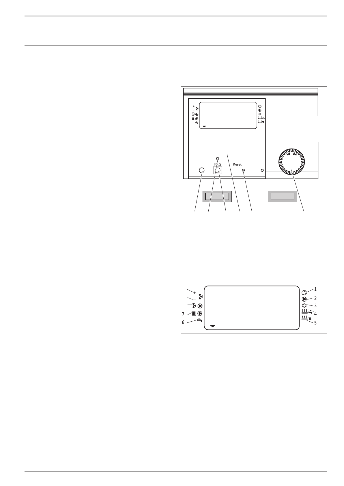
WPMiw heat pump manager
ROOM TEMP HCI
Time / Date
DHW temp.
Room temp. 1
Room temp. 2
Raumtemp. 1
Raumtemp. 2
Warmwassertemp.
Heizkurven
Heating curves
Zeit / Datum
Info temperatures
Heizprogramme
Holiday / Party prog.
Info Temperaturen
Ferien / Partyprog.
PRGPC Reset Auto
1 Rotary selector
2 Rotary selector Reset / Auto
3 Appliance menu
4 Programming key
5 Programming indicator
6 Optical interface RS 232
System status display
10
ROOM TEMP HCI
9
8
7
6
1 Compressor 1
2 Buffer cylinder primary pump
3 Cooling (only with a suitable hydraulic circuit)
4 Electric emergency/booster heater (DHW heating)
5 Electric emergency/booster heater (heating)
6 DHW heating
7 Circulation pump, heating circuit 1 “radiator circuit”
8 Circulation pump, heating circuit 2 “mixer circuit”
9 Mixer close
10 Mixer open
Start up
Heating prog
DHW program
Inbetriebnahme
Warmwasserprog.
2
3
1456
26�03�01�0073
1
2
3
4
5
26�03�01�1572
www.stiebel-eltron.com WPF basic | 5
Page 6
OPERATION
Operation
4.1 Operation
The operation is split over three control levels. Control levels 1
and 2 are accessible to users and contractors alike. Control level
3 is reserved for qualified contractors:
1. control level (control flap closed)
This enables the adjustment of operating modes, such as standby
mode, programmed operation, constant day or setback mode, etc.
2. control level (control flap open)
This enables system parameters, such as room temperatures, DHW
temperatures, heating programs, etc. to be adjusted.
3. control level (for contractors only)
This level is protected by a code and should only be used by a
contractor. Here, you can determine the specific details regarding
the heat pump and heating system.
4.2 Essential facts in brief
Settings
All settings follow the same pattern:
Opening the control flap toggles the manager into programming
mode. An indicator symbol
play at system parameter Room temp. 1. Turning the rotary selector allows you to move the indicator to the system parameter
you want to change.
To change the system parameter, press
dicator above illuminates, you can modify the current value by
turning the rotary selector . Press the key again; the indicator
then extinguishes and the new set value has been saved. You can
modify further values for this parameter by pressing again, if
the red indicator has not been extinguished above . The programming step can only be terminated when the red indicator
has extinguished.
Terminating the programming process
You can terminate the programming process after entering and saving the required parameter changes by closing the control flap. If you
want to make further changes, turn the rotary selector
display shows BACK, then press
ous level. Closing the control flap with illuminated indicator above
returns the manager into its original position. The modified
value will then not be saved.
is shown at the bottom of the dis-
. Whenever the red in-
until the
. This will return you to the previ-
Display including all display elements
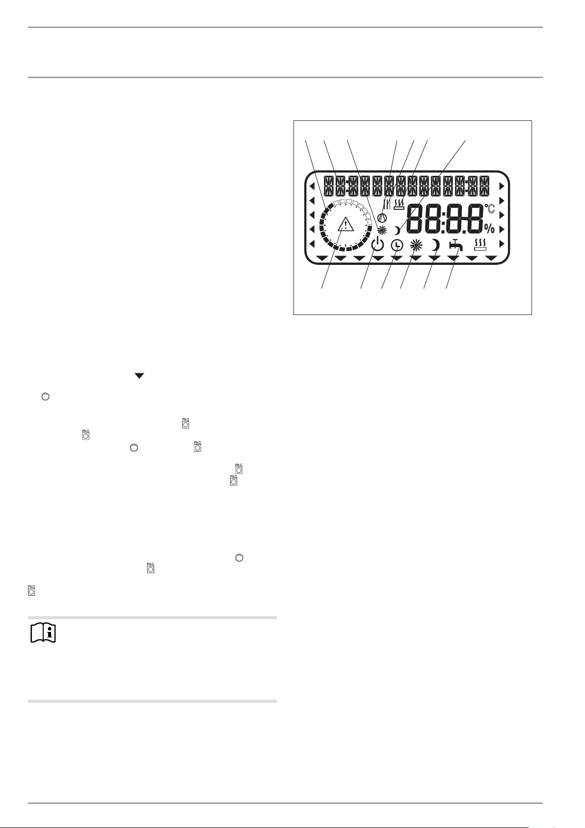
2 765431
24
18
13 12 11 10 9 8
1 Heating times for central heating and DHW (black)
2 14-digit plain text display
3 Day mode for heating circuit 1
4 Compressor running
5 Switching time pairs for central heating and DHW operation
6 2. heat source running
7 Setback mode for heating circuit 1
8 DHW mode
9 Constant setback mode
10 Constant day mode
11 Automatic mode
12 Standby mode
13 Fault message (flashing)
6
12
C
V
26�03�01�0075
Note
During commissioning, a system check will be implemented, e.g. all sensors that are currently connected are
displayed upon request. Sensors not connected before
the system went ‚live‘ are not registered by the manager
and are therefore not displayed. The indicator symbol
skips such system parameters.
Example: The system parameters DHW TEMP and DHW PROGRAM
will be skipped if, during commissioning, the DHW cylinder sensor
was not connected. und Warmwasserprog. übersprungen. Values
for these parameters, therefore, cannot be programmed.
6 | WPF basic www.stiebel-eltron.com
Page 7
OPERATION
Operation
4.3 Adjustments at control level 1
4.3.1 Operating modes
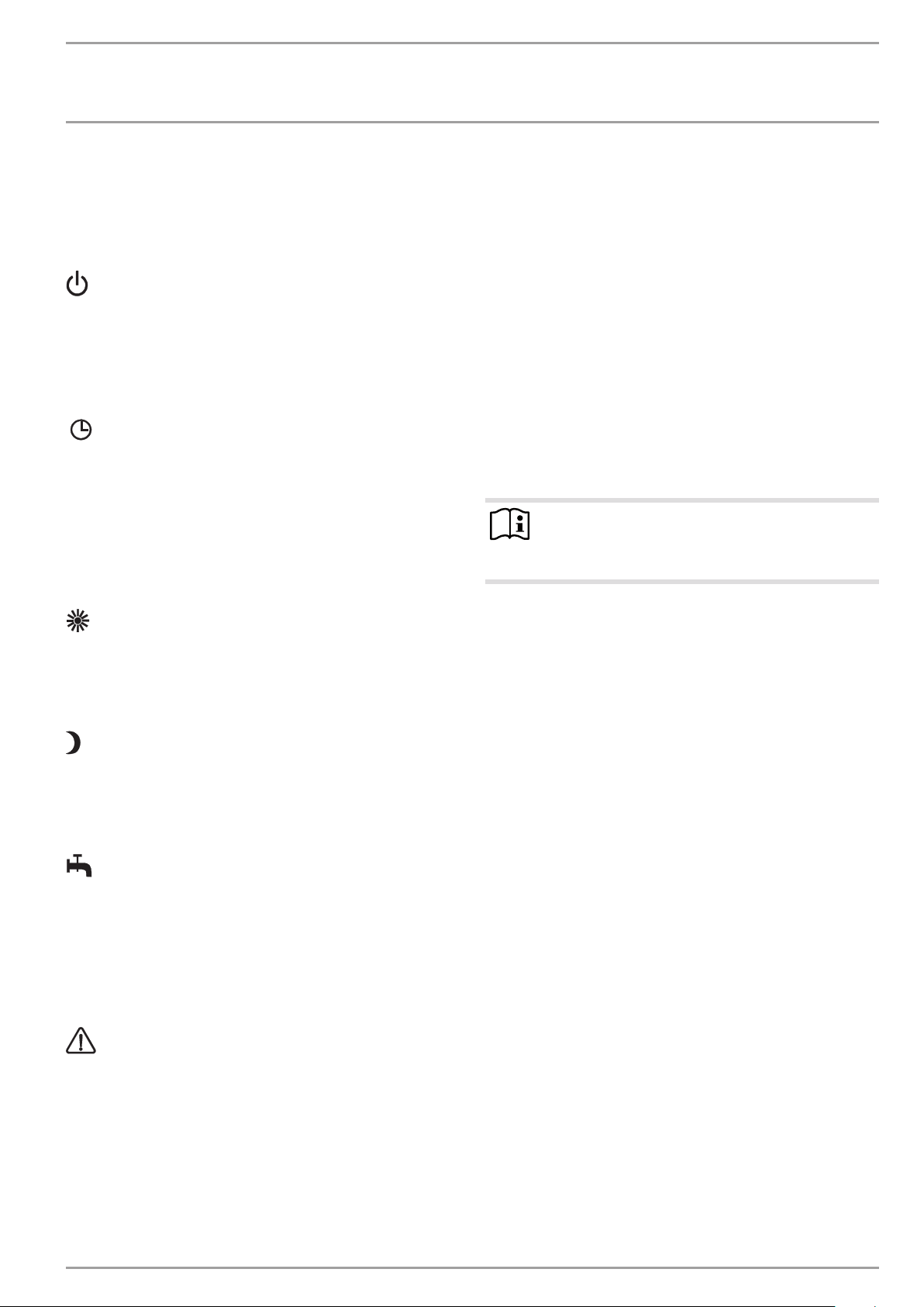
The operating modes are changed by turning rotary selector with
the control flap closed.
Standby mode
Frost protection is activated for heating and DHW mode. The display indicates frost protection when the flap is closed. The set
DHW value is fixed at 10 °C, the set heating flow value is calculated
based on a set room temperature of 5 °C.
Application: during holidays.
Automatic mode
Heating subject to time switch program (applies to heating circuits
1 and 2); changeover between day and setback temperatures. DHW
in accordance with a time switch program; changeover between
day and setback temperature, see point 4. In this operating mode,
an additional sun or moon symbol is displayed to indicate whether
heating circuit 1 is currently in day or setback mode. The remote
control is only active in this mode.
Application: When DHW and central heating are required.
Constant day mode
The heating circuit is constantly held at the day temperature (applicable to heating circuit 1 and heating circuit 2). DHW in accordance with a time switch program.
Application: Low energy houses without setback mode.
Constant setback mode
The heating circuit is constantly held at the setback temperature
(applicable to heating circuit 1 and heating circuit 2). DHW in
accordance with a time switch program.
Application: during weekends away.
DHW mode
DHW heating is regulated by a time switch program. If a time
program is enabled, the water inside the DHW cylinder is heated
to the set day temperature. At all other times, the water is heated to the set night temperature. Frost protection is activated for
heating operation.
Application: The heating season has ended; only DHW should be
generated.
Fault message (flashing)
Indicates faults in the heat pump system.
Notify your local contractor
4.4 Overview of control level 2
To access control level 2,
open the control flap.
Select the required parameter with the rotary selector.
The display shows the relevant parameter in plain text and an
arrow indicating the parameter’s location in the control level.
ROOM TEMP HC1
Here you can select the set room temperature for day and setback
mode for heating circuit 1.
ROOM TEMP HC2
Here you can select the set room temperature for day and setback
mode for heating circuit 2. The display ROOM TEMP2 will only be
displayed, if the mixer flow sensor for heating circuit 2 has been
connected.
Note
The actual room temperature can also be scanned if the
FE7 or FEK remote control has been connected and allocated to HC1 or HC2.
DHW TEMP
Here you can allocate a set day and night temperature to the
temperature inside the DHW cylinder.
TIME/DATE
Here you can adjust the time and summertime.
At the factory, summertime is set to begin on 25 March and to
end on 25 October.
HOLIDAY/PARTY
You can indicate the length of your holiday using the holiday program menu (start date, end date). The heat pump system operates in setback mode for the selected period. Frost protection is
activated for the DHW cylinder.
The party program menu item allows you to extend the day mode
by a few hours.
Temperatures
Here you can scan the heat pump or heat pump system sensor
temperatures, comparing set with actual values, the heating curve
gap, etc.
HEATING CURVES
Here you can select a heating curve each for heating circuit 1
and heating circuit 2. The room temperature will only remain
constant, irrespective of the outside temperature, if the correct
heating curve has been selected for the relevant type of building.
Selecting the correct heating curve is therefore vitally important.
HEATING PROG
Here you can adjust associated heating programs for heating circuits 1 and 2.
www.stiebel-eltron.com WPF basic | 7
Page 8
OPERATION
Operation
DHW PROGRAM
Here you select the times when the appliance will control DHW
heating using the set day value. At all other times, the appliance
controls DHW heating using the set night value.
COMMISSIONING
Note
The commissioning level (control level 3) may only be
altered by your contractor.
Here you need to determine the settings of control level 2 and the
system-specific parameters. These parameters are adjusted at
control level 3, access to which is protected by code.
Check all parameters in sequence, and enter all selected values
into the column (system value) provided in the commissioning
report.
4.4.1 Special features of the WPF in cooling mode
For the WPF in cooling mode, your qualified contractor selects
the room temperature for cooling mode at control level 3. Cooling
commences when the room temperature exceeds the set room
temperature.
Cooling terminates when the actual room temperature is 2 K lower
than the set room temperature.
4.5 Adjustments at control level 2
To make any adjustments at control level 2, open the control flap.
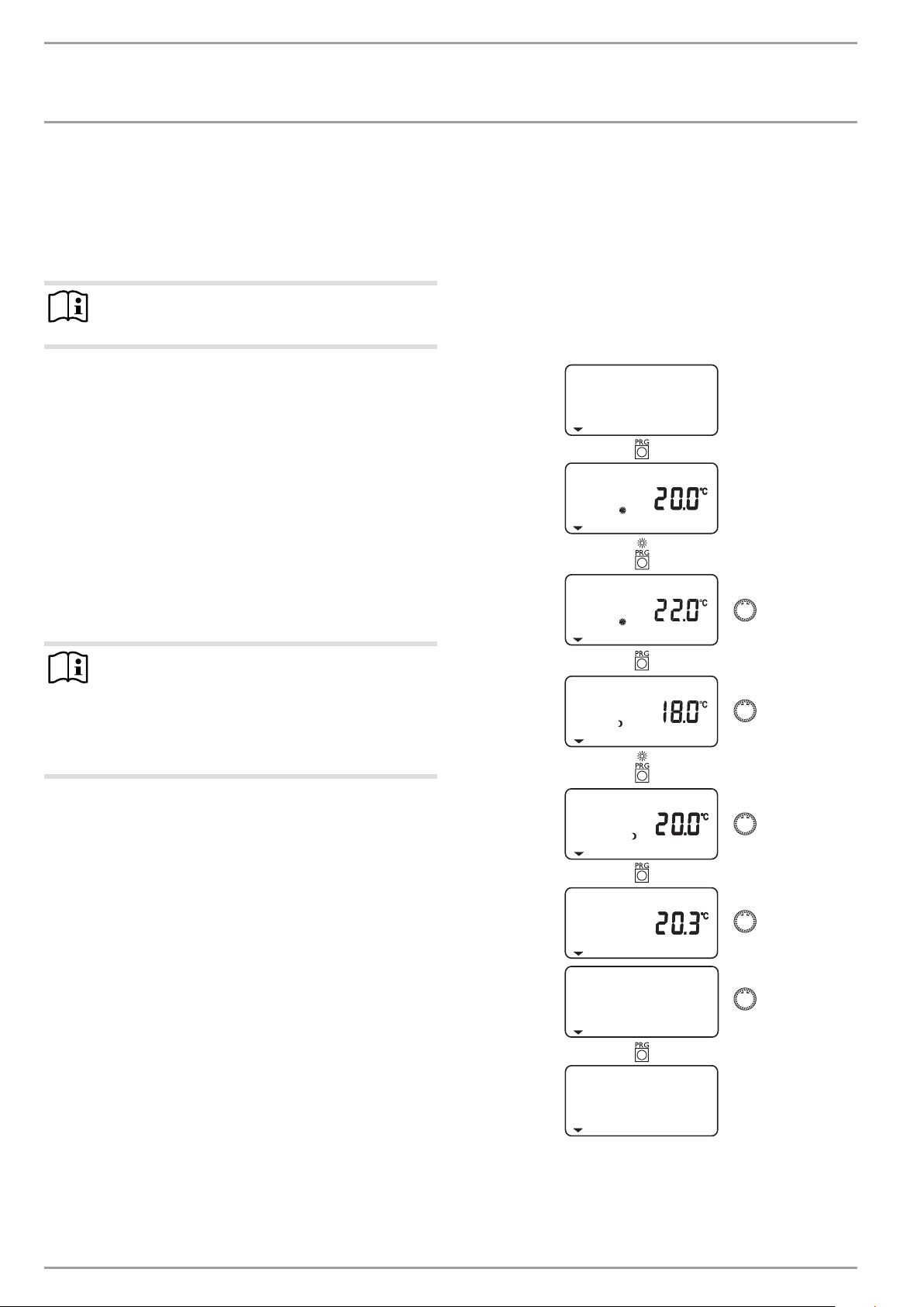
4.5.1 Room temperature HC 1
With menu item ROOM TEMP HC1, you can select the set room
temperature for day and setback mode for heating circuit 1. Changing this parameter results in a parallel offset of the heating curve.
The actual room temperature can also be scanned, as soon as the
FE7 or FEK remote control has been connected and allocated to
heating circuit 1.
ROOM TEMP HC1
SET ROOM T DAY
SET ROOM T DAY
Note
For cooling via cooling surfaces (underfloor heating or
wall heating systems), you also require the FEK remote
control. For cooling via fan-assisted convectors, you also
require the FEK or FE7 remote control.
Cooling via radiators would lead to moisture damage and
is therefore not permissible!
SET ROOM T NGT
SET ROOM T NGT
ACTUAL ROOM T
BACK
ROOM TEMP HC1
8 | WPF basic www.stiebel-eltron.com
Page 9
OPERATION
Operation
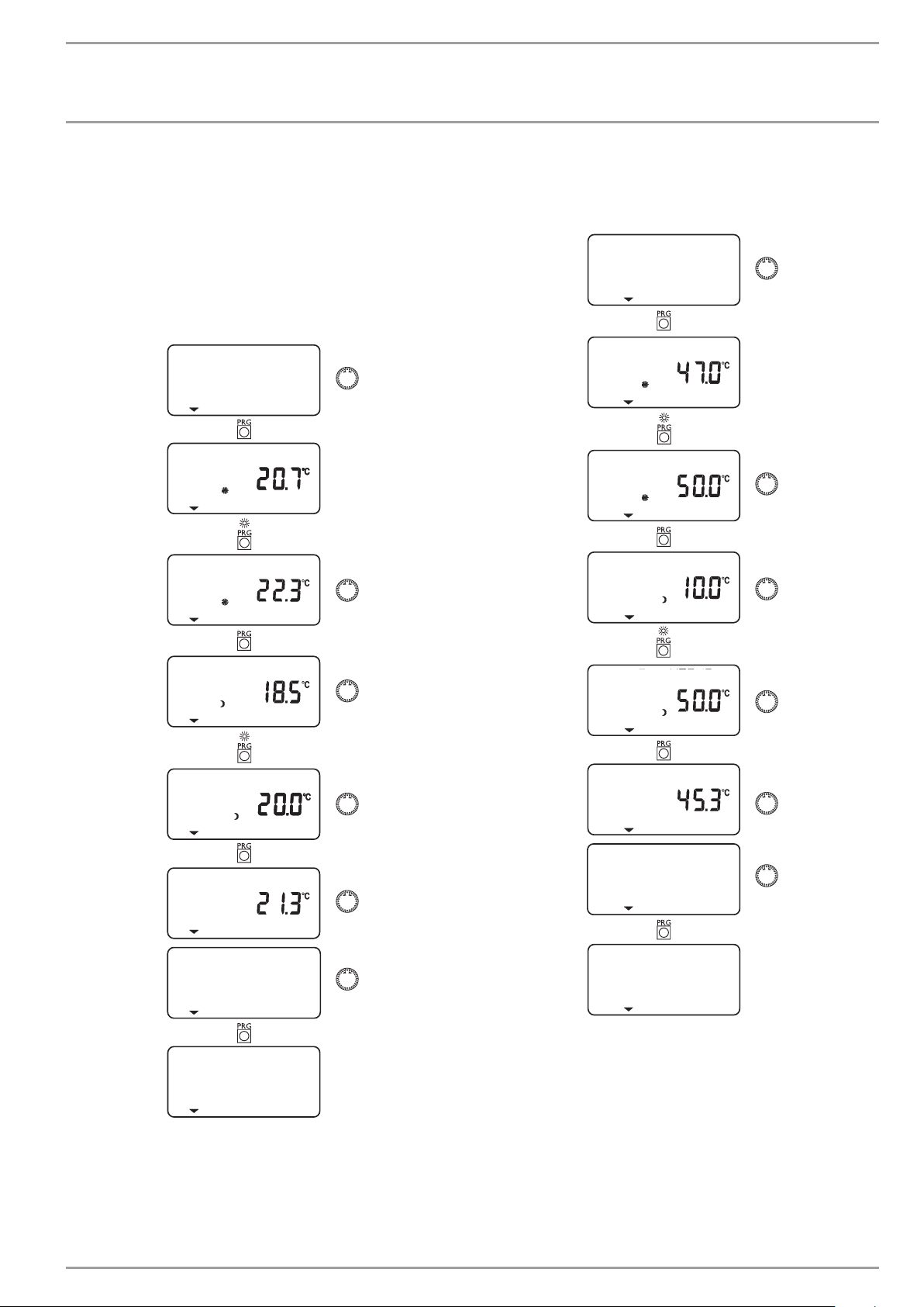
4.5.2 Room temperature, heating circuit 2
With menu item ROOM TEMP HC2, you can select the set room
temperature for day and setback mode for heating circuit 2. You
can change the room temperature, if you feel rooms are either
too hot or too cold. ROOM TEMP HC2 will only be displayed if the
mixer flow sensor is connected.
The actual room temperature can also be scanned, as soon as the
FE7 or FEK remote control has been connected and allocated to
heating circuit 2.
ROOM TEMP HC2
SET ROOM T DAY
SET ROOM T DAY
4.5.3 DHW temperature
With parameter 9, you can allocate a set day and night temperature to the temperature inside the DHW cylinder.
DHW TEMP
SET DHW T DAY
SET DHW T DAY
SET DHW T NGT
SET ROOM T NGT
SET ROOM T NGT
ACTUAL ROOM T
BACK
ROOM TEMP HC2
SET DHW T NGT
ACTUAL DHW T
BACK
DHW TEMP
www.stiebel-eltron.com WPF basic | 9
Page 10
OPERATION
Operation
4.5.4 Time and date
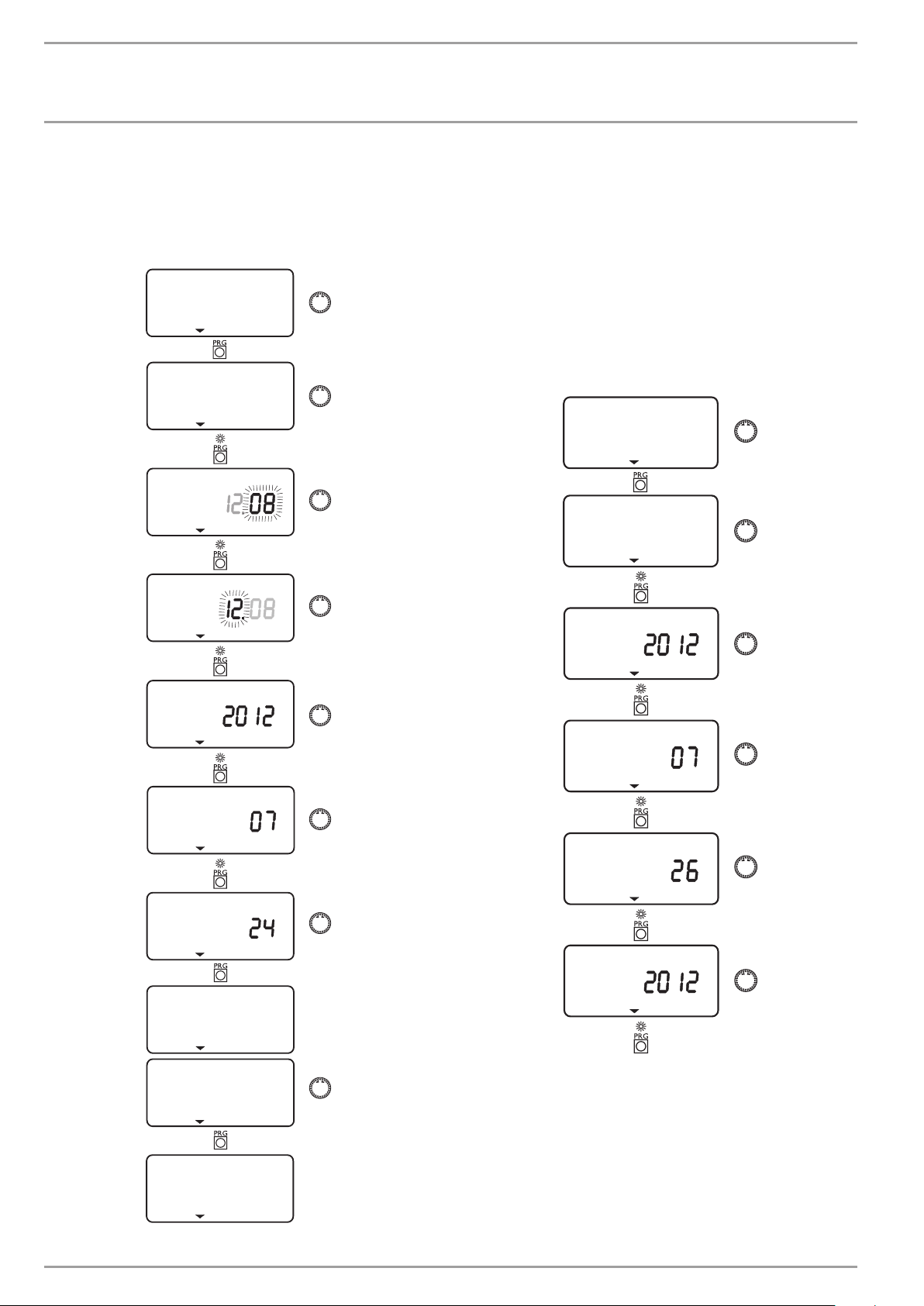
You can adjust the time and summertime with the TIME/DATE
menu item.
At the factory, summertime is set to begin on 25 March and to
end on 25 October.
TIME/DATE
SET CLOCK
TIME
TIME
4.5.5 Holiday and party program
In HOLIDAY MODE, the heat pump system runs in setback mode
and frost protection for DHW heating is enabled. Holiday mode
is displayed when the flap is closed. For the start of the holidays,
the year, month and day are entered; also enter the year, month
and day for the end of the holidays. The start time is 0:00 h on the
first day of the holidays. The end time is 24:00 h on the day the
holiday ends. After the holiday period has expired, the heat pump
system operates again in accordance with the previous heating
and DHW program.
In PARTY MODE, you can extend the day mode for central heating
by a few hours. This is displayed with the flap closed.
HOLIDAY/PARTY
HOLIDAY
YEAR
MONTH
DAY
SET CLOCK
YEAR START
MONTH START
DAY START
YEAR END
BACK
TIME/DATE
10 | WPF basic www.stiebel-eltron.com
Page 11
OPERATION
Operation
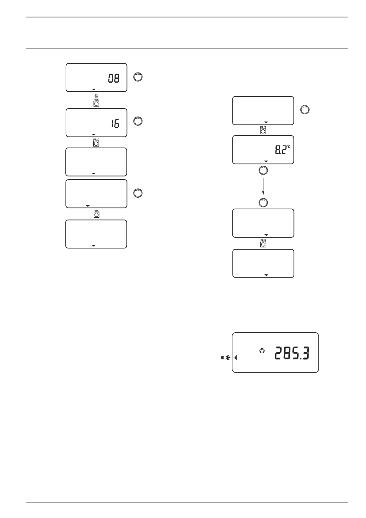
MONTH END
DAY END
HOLIDAY
BACK
HOLIDAY/PARTY
4.5.6 Temperatures
Under menu item TEMPERATURES, you can scan values of the heat
pump or heat pump system.
TEMPERATURES
OUTSIDE
BACK
TEMPERATURES
Actual or set temperatures will not be displayed if the corresponding sensor is not connected.
Example:
Compressor heat amount in heating mode since 0:00 h today in
KWh.
HEAT AMOU DAY kwh
www.stiebel-eltron.com WPF basic | 11
Page 12
OPERATION
Operation
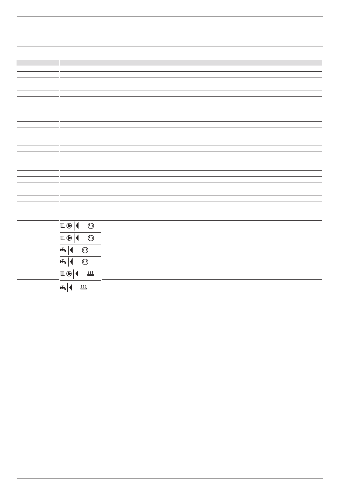
INFO WPM Meaning
external Outside temperature
ACT ROOM T FE7 Actual room temperature for heating circuit 1 (HC1) or heating circuit 2 (HC2) (will only be displayed if the FE7 remote control is connected)
SET ROOM T FE7 Set room temperature for heating circuit 1 or heating circuit 2 (will only be displayed if the FE7 remote control is connected)
REL HUMIDITY Relative humidity
DEW POINT TEMP Dew point temperature
SET DHW TEMP Set DHW temperature
ACTUAL RTRN T Actual heat pump return temperature - heating circuit 1
SET RTRN TEMP Set heat pump return temperature for heating circuit 1 (HC1). Fixed temperature is displayed for fixed temperature control
ACTUAL MIXER T Actual mixer flow temperature - heating circuit 2
SET MIXER TEMP Set mixer flow temperature - heating circuit 2
FIXED VALUE Set fixed temperature for heating circuit 1
SET BUFFER T Set buffer temperature (highest set value of heating circuits H1 and H2 (H3 if MSM is installed). Fixed temperature will be displayed for
ACTUAL FLOW T Actual heat pump flow temperature
SET FLOW HTG Set central heating flow temperature
ACTUAL SRCE T Actual heat source temperature
SET SRCE TEMP Minimum source temperature
DUAL-MODE HTG Dual-mode point - central heating
DUAL-MODE DHW Dual-mode point - DHW
HEAT LIMIT Limit temperature - central heating
DHW LIMIT Limit temperature - DHW
SYST FROST PRO System frost protection temperature
HOT GAS TEMP Compressor outlet temperature
HIGH PRESSURE HIGH PRESSURE
LOW PRESSURE Low pressure
HEAT AMOU DAY Compressor heat amount in heating mode since 0:00 h today.
set-value control)
TTL HEAT AMOU Total compressor heat amount in heating mode.
HEAT AMOU DAY Compressor heat amount in DHW mode since 0:00 h today.
TTL HEAT AMOU Total compressor heat amount in DHW mode.
TTL HEAT AMOU Total heat amount of the electric booster heater in heating mode
TTL HEAT AMOU Total heat amount of the electric booster heater in DHW mode
12 | WPF basic www.stiebel-eltron.com
Page 13
OPERATION
Operation
4.5.7 HEATING CURVES
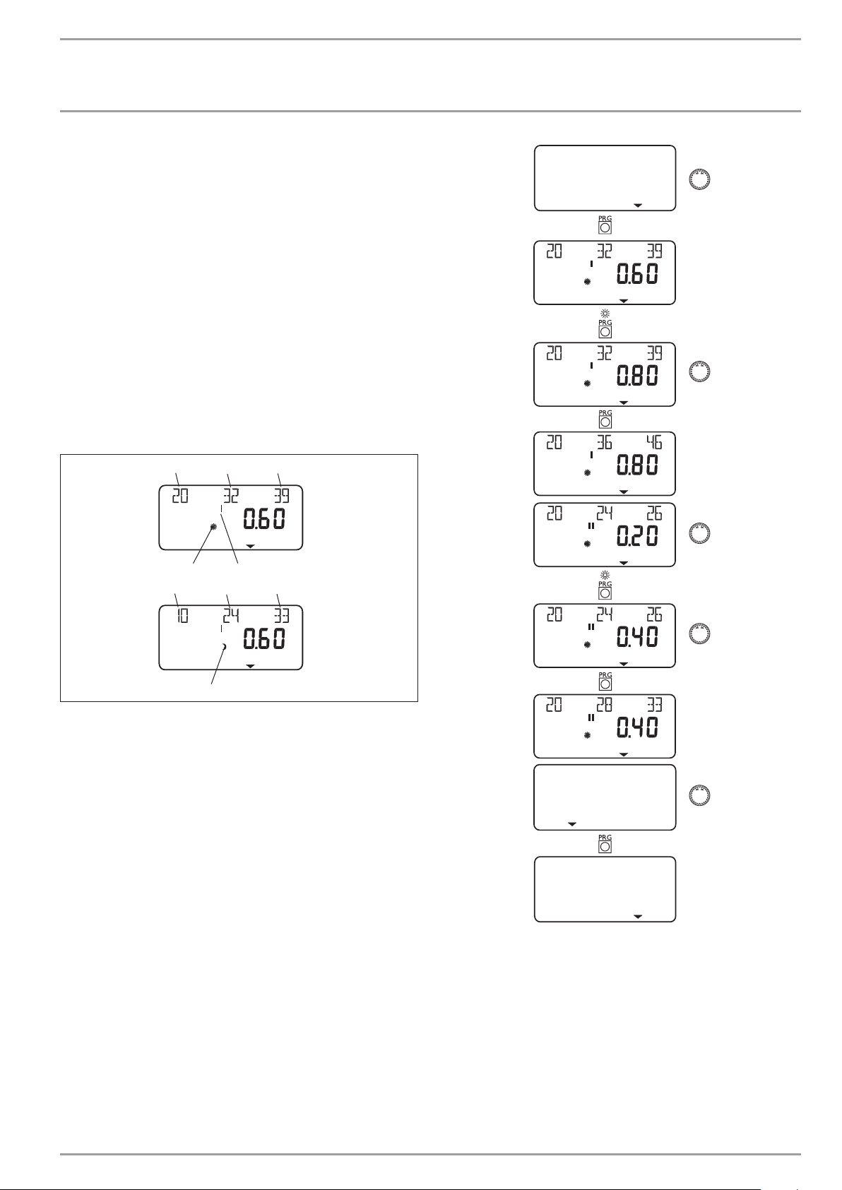
The HTG CURVE menu item enables you to adjust one HTG CURVE
each for heating circuit 1 and 2.
Note: Your contractor will have set up a building and system-specific optimum heating curve for every heating circuit. It relates to
the heat pump return temperature for heating circuit 1 and to the
mixer flow temperature for heating circuit 2.
When adjusting the heating curve on the heat pump manager, the
calculated set return or flow temperature, which is subject to the
outside temperature and the set room temperature, will be shown
at the top of the display.
As soon as a temperature has been preselected via the fixed temperature parameter at control level 3, heating circuit 1 will be
hidden, and the display will show FIXED VALUE with the relevant
temperature.
Adjusting the heating curve
1 32
HEATING CURVES
4
1 32
1 Relative to an outside temperature of +20 °C
2 Relative to an outside temperature of 0 °C
3 Relative to an outside temperature of -20 °C
4 Day mode
5 Heating circuit 1
6 Setback mode
5
6
C26�03�01�1068
BACK
HEATING CURVES
www.stiebel-eltron.com WPF basic | 13
Page 14
OPERATION
Operation
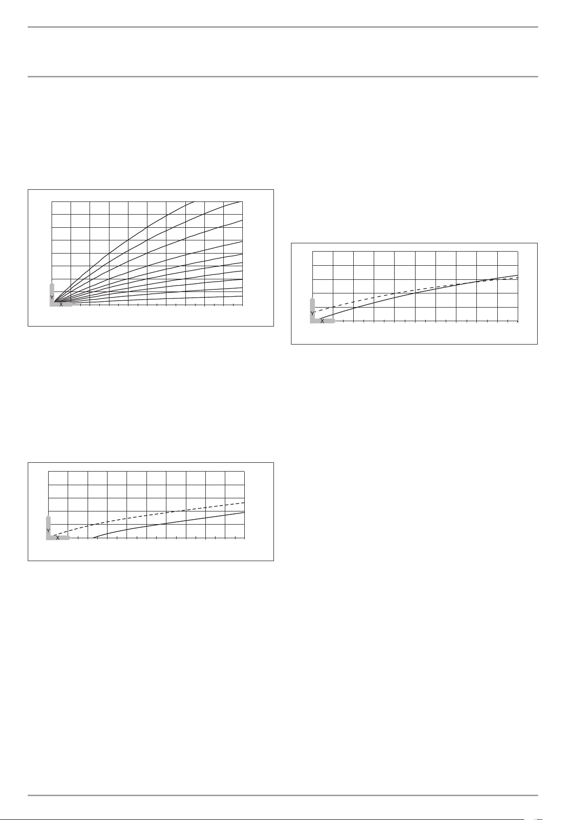
Heating curve diagram
One heating curve can be adjusted for heating circuit 1 and heating
circuit 2 respectively.
At the factory, heating curve 0.6 is set up for heating circuit 1 and
heating curve 0.2 for heating circuit 2.
These heating curves relate to a set room temperature of 20 °C.
-14
-16
-18
2,53
2
1,5
1,2
1
0,8
0,6
0,4
0,2
-20
100
80
60
40
20
2018161412
86420
10
-2-4-6
-8
-10
-12
Y Heating circuit 1, heat pump return temperature [°C]
Heating circuit 2, heat pump flow temperature [°C]
X Outside temperature [°C]
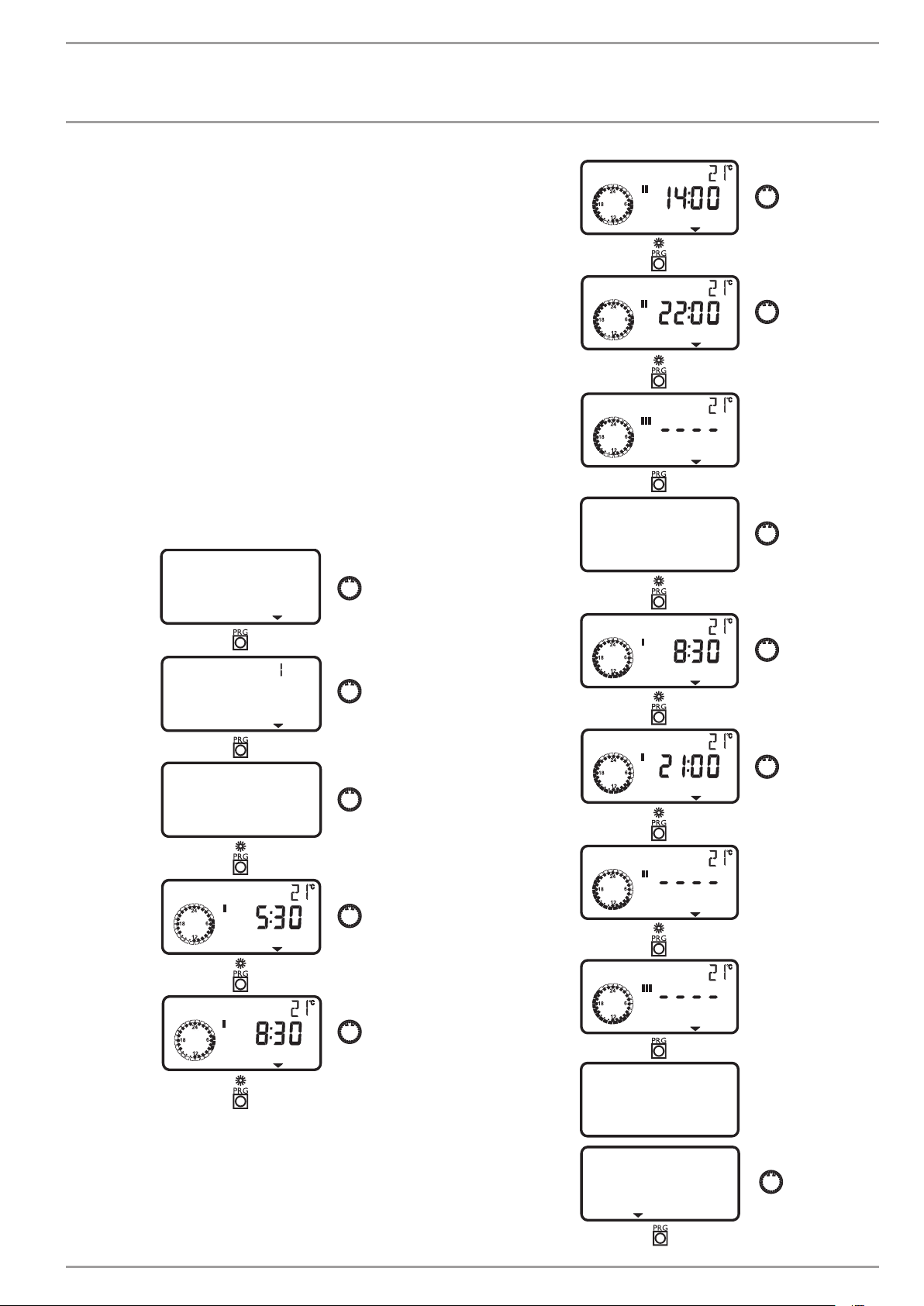
Adjustment of programmed changeover between day and
setback mode
The figure shows a standard heating curve with a slope of 0.8, relative to a set room temperature for day mode of 20°C. The bottom
curve is setback mode. The set room temperature is reduced to 15
°C for setback mode. The heating curve is shifted down parallel
to the original curve.
Adapting a heating curve
Example:
During spring and autumn, the temperature of a building’s heating
system is too low at an outside temperature between 5 °C and
15°C, despite open radiator valves, but is OK at outside temperatures of ≤ 0 °C. This problem can be remedied with a parallel offset
and a simultaneous reduction of the heating curve.
Prior to this adjustment, heating curve 1.0 was adjusted, relative
to a set room temperature of 20 °C. The dotted line indicates the
modified heating curve at 0.83 and a modified set room temperature at 23.2 °C.
70
60
50
40
30
26�03�01�1300
20
2018161412
86420
10
-2-4-6
-8
-10
-12
-14
Y Return/flow temperature [°C]
X Outside temperature [°C]
-16
-18
-20
26�03�01�1302
70
60
50
40
30
20
2018161412
86420
10
Y Return/flow temperature [°C]
X Outside temperature [°C]
1 Day mode
2 Setback mode
-2-4-6
1
2
-8
-10
-12
-14
-16
-18
-20
26�03 �01�1301
14 | WPF basic www.stiebel-eltron.com
Page 15
OPERATION
Operation
4.5.8 HEATING PROG
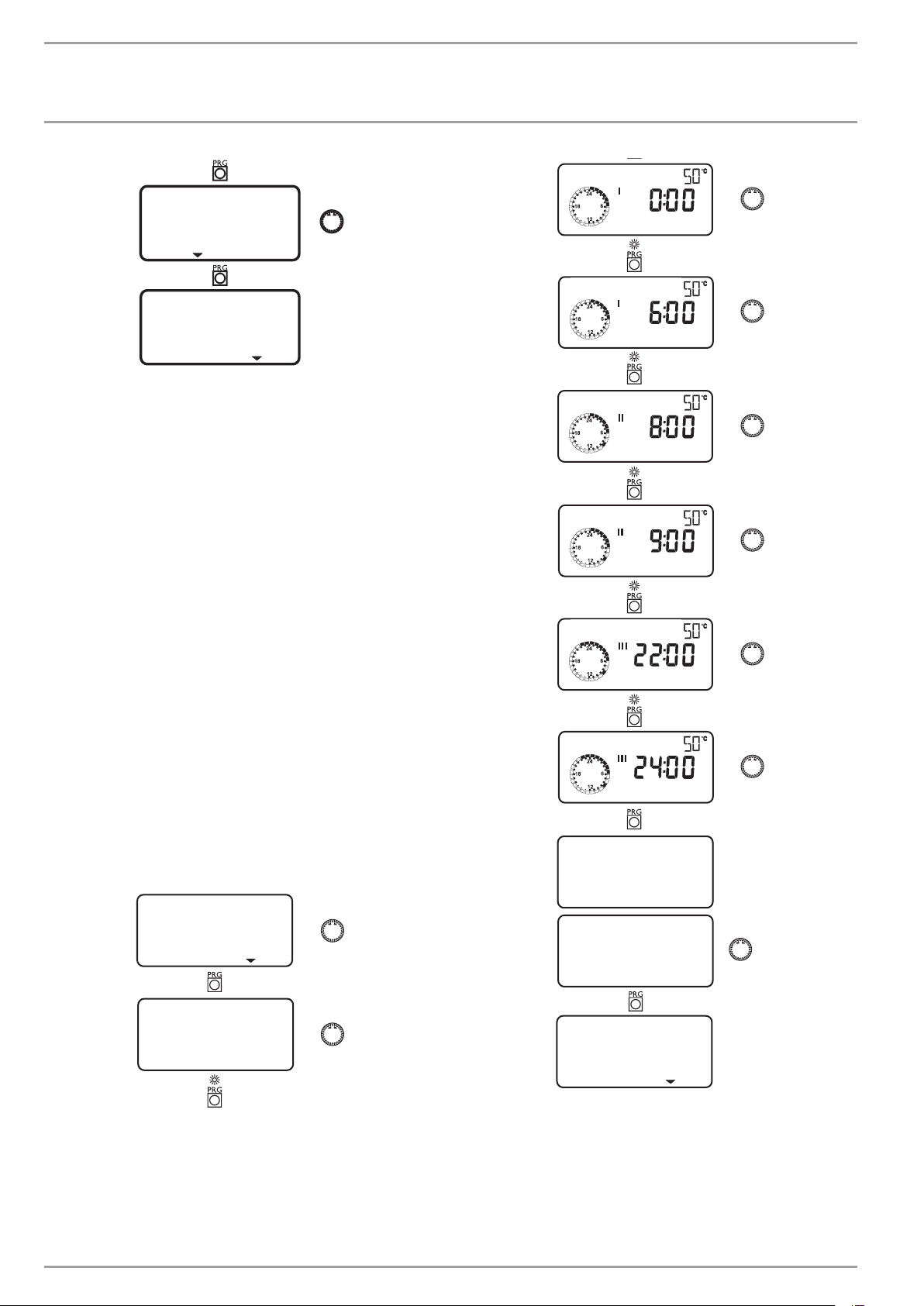
The HEATING PROG parameter enables you to determine when and
how often the appliance heats to the set day values for heating
circuit 1 and 2. At all other times, the appliance heats to the set
night temperature. You will have already selected the set values
under menu item ROOM TEMP HC1/2.
You can adjust your heating system as follows:
- for each individual day of the week (Monday, ..., Sunday)
- Monday to Friday (Mo – Fr)
- Saturday and Sunday (Sa – Su)
- the whole week (Mo – Su)
You can adjust three switching time pairs (I, II, III) for each of
these options.
Example:
For heating circuit 1, your heating system should provide heat
daily from Monday to Friday at two different times, i.e. from 05:30
h until 08:30 h as well as from 14:00 h until 22:00 h. For the
weekend, your heating system should provide heat from 08:30 h
until 21:00 h.
HEATING PROG
HEATING START
HEATING STOP
HEATING START
SAT–SUN
HEATING CIRC
MON–FRI
HEATING START
HEATING STOP
HEATING START
HEATING STOP
HEATING START
HEATING START
SAT–SUN
BACK
www.stiebel-eltron.com WPF basic | 15
Page 16
OPERATION
Operation
BACK
HEATING PROG
DHW START
DHW STOP
4.5.9 DHW programs
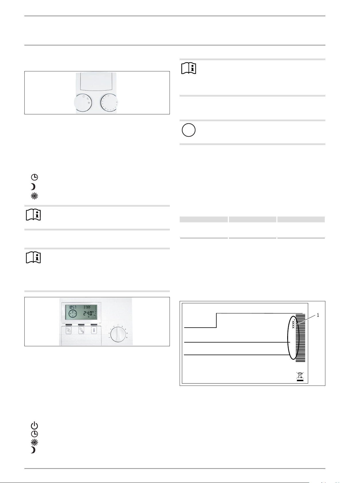
The DHW PROGRAM parameter enables you to select the times
when the appliance will control DHW heating using the set day
value. At all other times, the appliance controls DHW heating using
the set night value. You will have already selected the set values
under system parameter DHW TEMP. bereits eingestellt.
You can adjust your DHW heating as follows:
- for each individual day of the week (Monday, ..., Sunday)
- Monday to Friday (Mo – Fr)
- Saturday and Sunday (Sa – Su)
- the whole week (Mo – Su)
You can adjust three switching time pairs (I, II, III) for each of
these options.
Exception: You will need two switching time pairs, if you want to
heat DHW from 22:00 h until 06:00 h the following day.
Example:
You want to heat up DHW daily at two different times, i.e. from
22:00 h until 06:00 h the following day, and then from 08:00 h
until 09:00 h.
The day begins at 00:00 h; therefore begin programming for this
example at 00:00 h. The first switching times pair runs from 00:00
until 06:00 h. The second switching time pair runs from 08:00
until 09:00 h. The third switching times pair runs from 22:00 h
until 23:59 h.
DHW START
DHW STOP
DHW START
DHW STOP
MON–SUN
DHW PROGRAM
BACK
MON–SUN
16 | WPF basic www.stiebel-eltron.com
DHW PROGRAM
Page 17
OPERATION
Maintenance and care
4.6 Remote control FE7
With the FE7 remote control, the following options are available:
- changing the set room temperature for heating for heating
circuit 1 or 2 by ± 5 °C.
- changing the operating mode.
It offers the following controls:
- one rotary selector for changing the set room temperature
- one rotary selector with the following positions
-
Automatic mode
-
Constant setback mode
-
Constant day mode
Note
The remote control is only active when the WPMiw is in
automatic mode.
4.7 Remote control FEK
Note
The parameters heating curve, room temperature and
heating program are not shown at the WPMiw heat pump
manager if the FEK is pre-selected for a specific heating
circuit.
5. Maintenance and care
PIC00000609
Appliance and system damage
!
Maintenance work, such as checking the electrical safety,
must only be carried out by a qualified contractor.
A damp cloth is sufficient for cleaning all plastic and sheet steel
parts. Never use abrasive or corrosive cleaning agents.
Protect the appliance from dust and dirt ingress during building
work.
We recommend a regular inspection (to establish the current condition of the system), and maintenance by a qualified contractor if
required (to return the system to its original condition).
6. Troubleshooting
Fault Cause Remedy
There is no hot water or
the heating system stays
cold.
The fuse/MCB has blown/
has responded.
Check the fuse/MCB in
your fuse box/distribution panel.
Note
In cooling mode, the WPF requires the FEK for area cooling systems, e.g. underfloor heating systems, chilled
ceilings, etc. Apart from the room temperature, it also
determines the dew point temperature to prevent condensation.
With the FEK remote control, the following options are available:
- changing the set room temperature for heating for heating
circuit 1 or 2 by ± 5 °C.
- changing the operating mode.
It offers the following controls:
- one rotary selector for changing the set room temperature
- one “Away” button
- one “Info” button
- one key to select the following operating modes:
-
Standby mode
-
Automatic mode
-
Constant day mode
-
Constant setback mode
6.1 Other problems
If you cannot remedy the fault, notify your heating contractor. To
facilitate and speed up your enquiry, please provide the serial
number from the type plate. The type plate is located on the front
at the top on the right or left hand side of the casing.
Sample type plate
*xxxxxxxxxxxxxxxxxx*
PIC00000704
Montageanweisung beachten! Dichtheit geprüft!
1 Number on the type plate
Made in Germany
1
26�03�01�1736
www.stiebel-eltron.com WPF basic | 17
Page 18

INSTALLATION
Safety
INSTALLATION
7. Safety
7.1 General safety information
- Only qualified contractors should carry out installation, commissioning, maintenance and repair of the appliance.
- We guarantee trouble-free operation and operational reliability only if the original accessories and spare parts intended for the appliance are used.
7.2 Instructions, standards and regulations
Note
Observe all applicable national and regional regulations
and instructions.
7.2.1 Electrical installation
Appliance damage
!
The specified voltage must match the mains voltage. Observe the type plate.
WARNING electrocution
Carry out all electrical connection and installation work
in accordance with national and regional regulations.
DANGER Electrocution
Before any work, isolate the appliance from the power
supply at the control panel.
WARNING electrocution
Only use a permanent connection to the power supply.
The appliance must be able to be separated from the
power supply by an isolator that disconnects all poles
with at least 3mm contact separation. This requirement
can be met by contactors, isolators, fuses etc.
8. Appliance description
8.2 Standard delivery
Delivered with the appliance:
- 1 outside temperature sensor AFS 2
9. Preparations
9.1 General information
Note
The appliance is designed for internal installation, except
in wet areas.
Never install the appliance directly below or next to
bedrooms.
Protect pipe transitions through walls and ceilings with an-
ti-vibration insulation.
The room in which the appliance is to be installed must meet the
following conditions:
- No risk from frost.
- The room must not be subject to a risk of explosions arising
from dust, gases or vapours.
- When installing the appliance in a boiler room together with
other heating equipment, ensure that the operation of other
heating equipment will not be impaired.
- The volume of the installation room should be at least
13.8m³.
- Load-bearing floor (for the weight of the internal unit, see
chapter „Specification / Data table“).
For installation on floating screeds, make provisions for quiet
heat pump operation.
Isolate the mounting surface around the heat pump by re-
cesses. After completing the installation, seal these recesses
with a water-impervious and sound insulating material, such
as silicone for example.
1 2 3 54
8.1 Mode of operation
Environmental energy is extracted by the heat exchanger on the
heat source side (evaporator). Any energy extracted is transferred,
together with the energy drawn by the compressor drive, to the
heating water by a heat exchanger on the heating water side
(condenser). Subject to the heat load, the heating water can be
heated to +60°C. The DHW is heated via the internal indirect coil
inside the DHW cylinder.
The electric booster heater (internal HS 2) starts if the high pressure sensor or the hot gas limiter responds during DHW heating.
In addition it can cover any residual heat demand, if the heating
system demand exceeds the heat pump output.
18 | WPF basic www.stiebel-eltron.com
1 Concrete base
2 Impact sound insulation
3 Floating screed
4 Floor covering
5 Recess
26�03�01�1466
Page 19
INSTALLATION
Mounting
9.2 Electrical installation
In accordance with VDE 0298-4, use the following cable cross-sections subject to their fuse protection:
Fuse/MCB
rating
C 16 A Compressor
B 16 A
C 16 A
C 25 A
C 35 A
B 16 A Control circuit fuse
C 16 A Control circuit fuse
The electrical data is given in the “Specification” chapter.
Provide separate fuses for the two power circuits of the appliance
and the control unit.
Assignment Cable cross-section
(three phase)
Electric emergency/
booster heater (BH)
(three phase)
Compressor
WPF 5 S basic
(single phase)
Compressor
WPF 7 S basic /
WPF 10 S basic
(single phase)
Electric emergency/
booster heater (BH)
(single phase)
(three phase)
(single phase)
2.5 mm²
2.5 mm²
1.5 mm² with only two live cores and
routing on a wall or in an electrical conduit on a wall.
1.5 mm² for open routing. Note the type
of routing!
2.5 mm² for routing through a
wall. Note the type of routing!
4.0 mm² for open routing. Note the type
of routing!
6.0 mm² for routing through a
wall. Note the type of routing!
4.0 mm² when routing a multi core line
on a wall or in an electrical conduit on
a wall.
6.0 mm² for routing through a
wall. Note the type of routing!
1.5 mm²
1.5 mm²
10. Mounting
10.1 Handling
Transport the appliance in its packaging to protect it against
damage.
Protect the appliance against heavy impact during transport.
- Only allow the appliance to be tilted during transport for a
short time to one of its longitudinal sides.
The longer the appliance is tilted, the greater the distribution
of refrigerant oil in the system.
- Storage and transport at temperatures below - 20 °C and in
excess of + 50 °C are not permissible.
10.2 Positioning
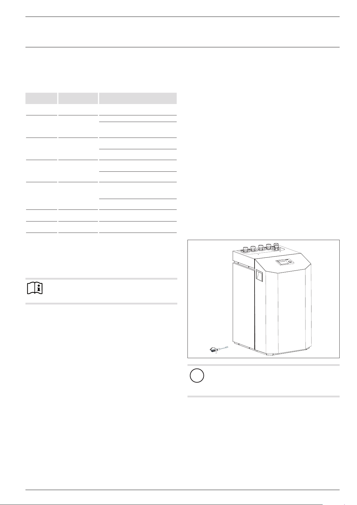
Remove the packaging film and the top and side EPS
padding.
Tilt the appliance backwards slightly and remove it from the
pallet.
Position the appliance on the prepared substrate.
Observe the minimum clearances (see chapter “Dimensions
and connection”).
Remove the six screws from the appliance plinth, and set
down the casing onto the floor.
9.3 Buffer cylinder
Note
In combination with the WPF 13 basic and the WPF 16
basic, it is absolutely imperative to use a buffer cylinder.
A buffer cylinder is recommended to ensure trouble-free appliance
operation.
The buffer cylinder provides hydraulic separation of the flow rates
in the heat pump circuit and the heating circuit.
When operating without a buffer cylinder, observe the details
specified in the chapter “Minimum flow rate without buffer
cylinder”.
6x
Appliance damage
!
The casing must stand on the floor free from the refrigeration unit. D. h. That means, the six plinth screws must
not be refitted.
26�03�01�1573
www.stiebel-eltron.com WPF basic | 19
Page 20
INSTALLATION
Mounting
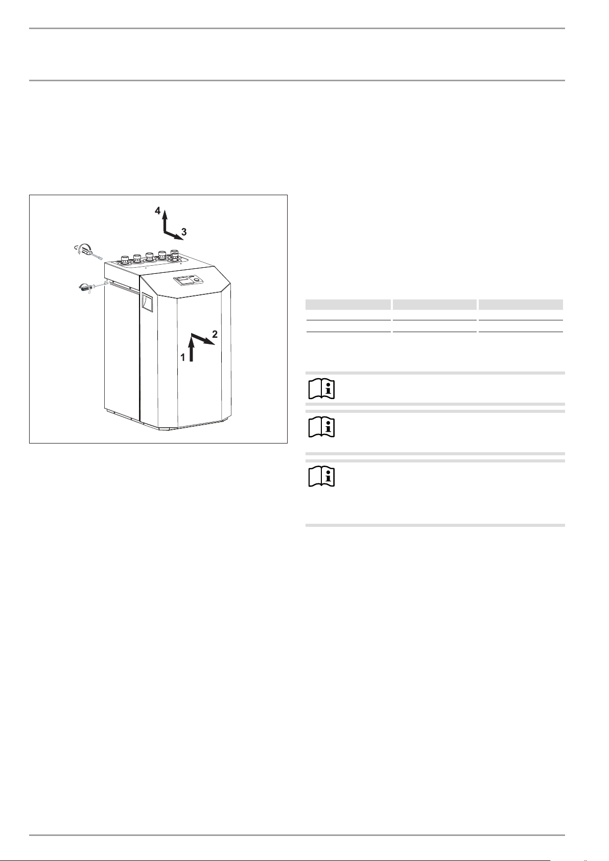
10.3 Removing the casing panels
When removing the front cover ensure, that the cables, which
connect the heat pump manager with the control panel, are not
torn off.
The same applies to the earth connection which electrically connects the front cover to the casing.
2x
4x
10.4.3 Connection and filling with brine
Prior to connecting the heat pump, check the heat source circuit
for possible leaks, and flush thoroughly.
Calculate the volume of the heat source circuit. The brine volume
of the heat pump under operating conditions can be found in the
data table (see chapter “Specification”).
The overall volume is equal to the required amount of brine made
by mixing undiluted ethylene glycol and water. The chloride content of the water must not exceed 300 ppm.
Mixing ratio
The brine concentration varies when using a ground collector or
a geothermal probe as a heat source.
The mixing ratio can be found in the table below.
Ethylene glycol Water
Geothermal probe 25 % 75 %
Geothermal collector 33 % 67 %
Charging the brine circuit
Note
The WPF S series does not have a brine pressure switch.
10.4 Installing the heat source system
Design the heat source system for the ground source heat pump
in accordance with the technical guides.
10.4.1 Permitted brine:
- Heat transfer medium as concentrate on an ethylene glycol
base, part no: 231109
- Heat transfer medium as concentrate on an ethylene glycol
base, part no: 161696
10.4.2 Circulation pump and required flow rate
Use a circulation pump with compound-filled windings to supply
the brine, to prevent an earth short circuit through condensate in
the electrical part of the pump (cold water version).
Size the circulation pump in accordance with the system-specific
conditions, h. i.e. nominal flow rate and pressure drop must be
taken into consideration (see “Specification”).
An adequate flow rate must be safeguarded at every possible
brine temperature, i.e.:
Nominal flow rate at a brine temperature of 0°C with a tolerance
of +10%.
Note
26�03�01�1574
The brine/water heat pump is equipped with a brine pressure
switch in the brine circuit. The brine pressure switch prevents
brine getting into the ground if there is a leak in the brine circuit.
If the pressure in the brine circuit falls below 0.7bar, the brine
pressure switch turns the heat pump off. In order for the heat
pump to be enabled again, the pressure must be raised to at least
1.5bar while the heat pump is on standby.
To prevent the brine pressure switch turning the heat pump off
when there is no leak, charge the heat source side of the heat
pump during installation with a minimum pressure of >1.5bar.
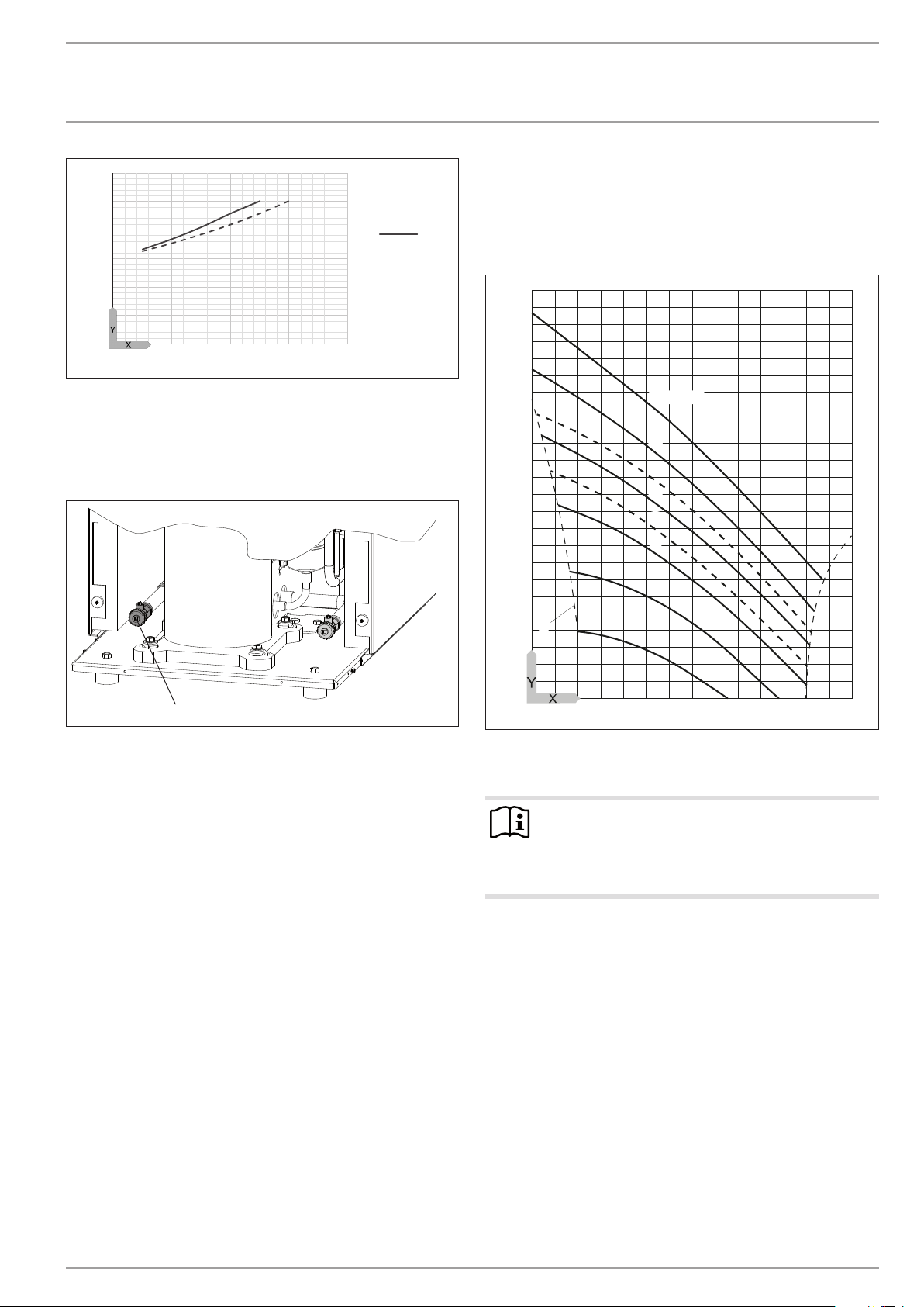
Fill the system according to the following curve.
Insulate the brine lines with diffusion-proof thermal
insulation.
Note
The brine pressure switch is bridged to the power supply
utility contact at the factory.
To activate the brine pressure switch, remove the
jumper.
20 | WPF basic www.stiebel-eltron.com
Page 21
INSTALLATION
1
2
Mounting
3
2,5
2
1,5
1
0,5
0
0 200 400 600 800
X System volume [l]
Y Charge pressure [bar]
1 Required charge pressure subject to the system volume with
33% brine
2 Required charge pressure depending on system volume with
25% brine
Check the brine concentration:
Determine the density of the ethylene glycol/water mixture,
e.g. with a hydrometer.
Using the actual density and temperature, you can check the current concentration in the diagram.
1,10
1,09
1,08
D0000058692
1,07
1,06
1,05
1,04
1,03
1,02
1,01
50 Vol.-%
40
33
30
25
20
10
1
1 Drain, brine side
Fill the brine circuit via the drain.
After filling the system with brine and prior to commissioning,
open the drain until brine runs out of it. No water must remain in
the pipe run to the drain.
A
1,00
0,99
0,98
26�03�01�1606
-20 0 20 40 60 80 100
0
X Temperature [°C]
Y Density [g/cm³]
A Frost protection [°C]
Note
The quoted details refer to ethylene glycol. These details
will differ slightly (see “Specification”) when using propylene glycol and the heat transfer medium as readymixed solution.
Thermally insulate all brine pipes with vapour-proof material.
To prevent the transmission of noise, connect the heat source
circuit to the heat pump with flexible pressure hoses.
26�03�01�1914
www.stiebel-eltron.com WPF basic | 21
Page 22

INSTALLATION
Mounting
10.4.4 Checking the heat source flow rate
The heat source flow rate is set via the temperature differential of
the heat source circuit.
Calculate the temperature differential. For this, operate the
appliance in heating mode or DHW mode.
Max. temperature differential of heat source circuit
6
5
4
3
2
1
-5 0 5 10 15 20
Y Max. temperature differential [K]
X Source inlet temperature [°C]
1 Heating flow 35 °C
2 Heating flow 50 °C
Note
You can check the source outlet temperature on the heat
pump manager display under system parameter TEMPERATURES.
1
2
10.5 Heating water connection
The heat pump heating system must be installed by a qualified
contractor in accordance with the water installation drawings that
are part of the technical documents.
Thoroughly flush the pipework before connecting the heat
pump. Foreign bodies, such as welding beads, rust, sand,
sealant, etc. can impair the operational reliability of the heat
pump.
Connect the heat pump on the hot water side. Check for
tightness.
Ensure the correct connection of the heating flow and return.
Provide thermal insulation in accordance with applicable regulations.
For sizing the heating circuit, note the maximum available external
pressure differential.
10.6 Oxygen diffusion
diffusion may lead to corrosion on the steel components of the
heating system (e.g.on the indirect coil of the DHW cylinder, on
buffer cylinders, steel radiators or steel pipes).
In the event of oxygenation, separate the heating system be-
tween the heating circuit and the buffer cylinder.
Material losses
!
The products of corrosion (e.g.rusty sludge) can settle in the heating system components, which may result in a lower output or fault shutdowns due to reduced
cross-sections.
10.7 Filling the heating system
Fill the heating system via the drain.
84�03�01�0017
1
1 Drain, heating side
Water quality
A fill water analysis must be carried out before the system is
filled. This may, for example, be requested from the relevant water
supply utility.
Material losses
!
To avoid damage as a result of scaling, it may be necessary to soften or desalinate the fill water. The fill water
limits specified in chapter "Specification / Data table"
must always be observed.
Recheck these limits 8-12 weeks after commission-
ing and as part of the annual system maintenance.
Note
With a conductivity >1000μS/cm, desalination treatment
is recommended in order to avoid corrosion.
Note
Suitable appliances for water softening and desalinating,
as well as for charging and flushing heating systems, can
be obtained via trade suppliers.
26�03�01�1606
Material losses
!
Avoid open vented heating systems and underfloor heating systems with plastic pipes which are permeable to
oxygen.
Note
If you treat the fill water with inhibitors or additives, the
same limits as for desalination apply.
10.8 Venting the heating system
In underfloor heating systems with plastic pipes that are permeable to oxygen and in open vented heating systems, oxygen
22 | WPF basic www.stiebel-eltron.com
Vent the pipework carefully.
Page 23
INSTALLATION
Mounting
10.9 Minimum flow rate of heat sink for WPF 5-16
basic
The heat pump is designed in such a way that no buffer cylinder
is required to provide hydraulic separation of the flow in the heat
pump circuit and the heating circuit in conjunction with space
heating systems.
However, in conjunction with radiators or an installation with
several heating circuits, the use of a buffer cylinder or a low loss
header is recommended.
The WPF 13 and 16 appliances must, in any case, always be operated with a buffer cylinder or a low loss header.
Risk of damage!
!
The minimum flow rate to ensure perfect heat pump operation must be maintained at every operating point of
the heat pump.
10.9.1 Minimum flow rate without buffer cylinder
The minimum flow rate is set using the temperature differential
of the heating system.
Set the heating circuit pump to ∆p-constant. Set ∆p-constant to a
value at which the temperature reaches or falls below the maximum temperature differential.
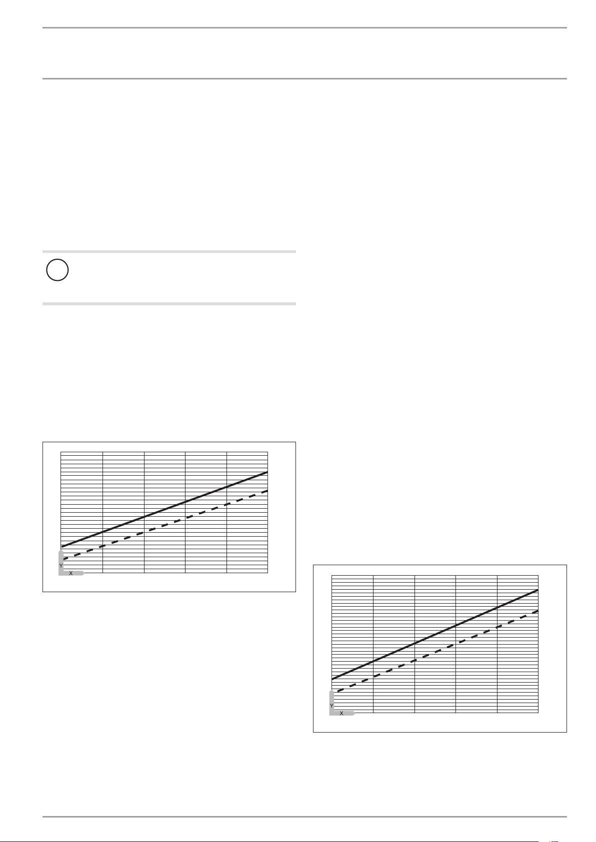
Max. temperature differential on the heating side without
buffer cylinder
18
16
14
12
10
8
1
2
Set the head of the circulation pump to a level that safe-
guards the flow rate required to operate the heat pump.
Check the final setting in DHW mode and adjust if required.
Fully open the overflow valve.
Close the overflow valve one turn at a time until the return to
the heat pump or the installed radiators become noticeably
warm.
If no overflow can be detected in the overflow valve using the
temperature sensor, close the heating circuit and heating circuit
valves and check the overflow valve is working.
Individual room control via remote control FE7 or FEK
In this case, one or more heating circuits in the heating system
must be left open. The open heating circuit(s) should be installed
in the lead room (room in which the remote control is installed,
e.g. the living room). The individual room can then be controlled
via the FE7 or FEK remote control, or indirectly by adjusting the
heating curve. The other rooms can be equipped with zone valves
or thermostatic valves.
Fully open the heating circuit(s).
Isolate by temporarily removing the fuse from the second in-
ternal heat source (DHC electric booster heater).
Operate the appliance in heating mode.
Set the head of the circulation pump to a level that safe-
guards the flow rate required to operate the heat pump.
Check the final setting in DHW mode and adjust if required.
10.9.2 Minimum flow rate with buffer cylinder or low loss
header
The minimum flow rate is set via the temperature differential of
the buffer circuit.
Set the heating circuit pump to ∆p-constant. Set ∆p-constant to a
value at which the temperature reaches or falls below the maximum temperature differential.
Max. temperature differential on the heating side with buffer
cylinder or low loss header
6
-5 0 5 10 15 20
12
84�03�01�0091�
11
1
Y Max. temperature differential [K]
X Source inlet temperature [°C]
1 Heating flow 35 °C
2 Heating flow 50 °C
In heating mode without a buffer cylinder, there are two possible
ways to safeguard the minimum flow rate:
Installing an overflow valve
Install an overflow valve with an internal diameter that is matched
to and sized for the heating system, and adjust it as follows:
Fully open the heating circuit(s).
Isolate by temporarily removing the fuse from the second in-
ternal heat source (DHC electric booster heater).
Fully close the overflow valve.
Operate the heat pump in heating mode.
10
9
8
7
6
5
4
-5 0 5 10 15 20
Y Max. temperature differential [K]
X Source inlet temperature [°C]
1 Heating flow 35 °C
2 Heating flow 50 °C
2
Isolate by temporarily removing the fuse from the second in-
ternal heat source (DHC electric booster heater).
www.stiebel-eltron.com WPF basic | 23
84�03�01�0090�
Page 24
INSTALLATION
Mounting
Operate the appliance in heating mode.
Set the head of the circulation pump to a level that safe-
guards the flow rate required to operate the heat pump.
Check the final setting in DHW mode and adjust the setting if
required.
10.10 Flow rate of heat sink for WPF 5-10 S basic
10.10.1 Circulation pump (cylinder primary pump)
The cylinder primary pump is integrated into the WPF. Consider
the available external head of 2.8 m when sizing the anti-vibration mounts and the pipework between the heat pump and the
buffer cylinder.
When utilising the WPF for DHW heating, ensure that the connection between the heat pump and the DHW cylinder is sized so
that the total pressure drop outside the heat pump is less than the
available external head of 2.8 m.
10.10.2 Circulation pump (heating circuit pump)
If no cylinder (buffer cylinder) is used, consider the maximum
external pressure of 280 hPa when sizing the heating circuit. Safeguard the nominal flow rate of the heat pump under all operating
conditions of the heating system by installing an overflow valve.
10.11 DHW heating
For DHW heating, a DHW cylinder with internal indirect coil is
required. The minimum coil surface area required is 3 m³.
A three-way diverter valve is integrated into the WPF between the
DHW heating circuit and the central heating circuit.
Connect the DHW flow of the appliance to the upper coil con-
nection of the DHW cylinder (see Specification / Connections).
Connect the DHW return of the appliance to the lower coil
connection of the DHW cylinder.
10.12 Electrical connection
Only qualified electricians must carry out the installation in accordance with these instructions.
DANGER Electrocution
Before any work, isolate the appliance from the power
supply at the control panel.
Permission to connect the appliance may need to be obtained from
your local power supply utility.
The terminals are located in the appliance control panel.
Note
Observe the chapter “Removing the casing parts”
when the appliance is closed.
Use appropriate cables in accordance with local regulations for
all connections.
Open the control panel’s cover flap. To do so, remove the fix-
ing screws on the side at the top of the control panel.
Route all connecting cables and sensor leads through the
entries in the back panel (see chapter “Connections and
dimensions”).
Route all cables through the strain reliefs.
Connect the cables according to the following diagrams.
Then check the function of the strain relief fittings.
Material losses
!
The compressor must only rotate in one direction. Change
the direction of rotation by interchanging two phases, if
the fault NO POWER appears in the WPMiw display when
the compressor starts.
Connected load of the electric booster heater
Connect the electric booster heater to ensure acceptable DHW
convenience. Mark the box in front to the terminal ratings on the
relevant label below the type plate.
Note
When closing the appliance, observe chapter “Fitting
the casing parts”.
24 | WPF basic www.stiebel-eltron.com
Page 25
INSTALLATION
L1 L2 L3 N L1 L2 L3 L1’ L2’ L3’
ONKSKühlen
F8
Mounting
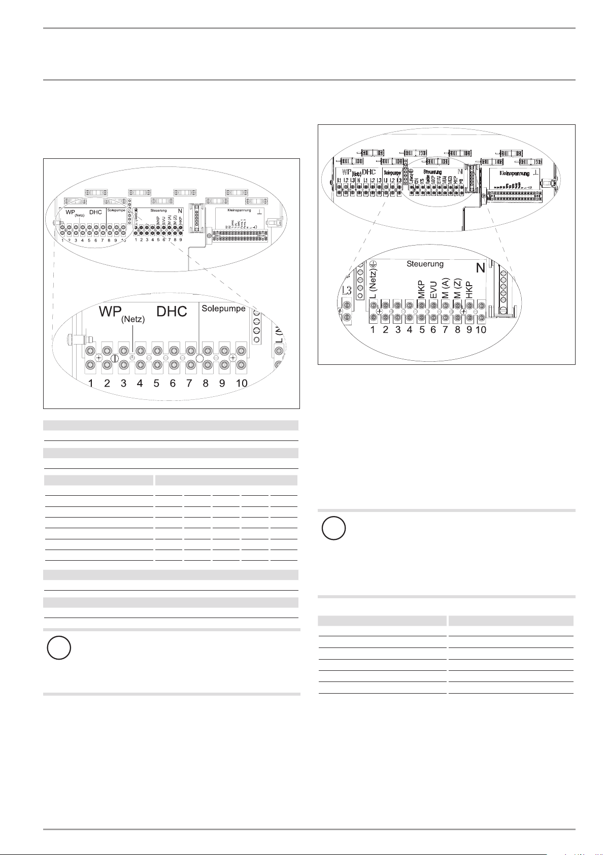
10.12.1 Electrical connection WPF basic (three-phase)
Connection X3: Heat pump, electric booster heater and brine
pump
L1 L2 L3 N L1 L2 L3 L1’ L2’ L3’
Heat pump power supply (compressor)
L1, L2, L3, PE
DHC power supply (electric booster heater)
L1, L2, L3, N, PE
Connected load Terminal assignment
2.6 kW L1 N PE
3.0 kW L2 N PE
3.2 kW L3 N PE
5.6 kW L1 L2 N PE
5.8 kW L1 L3 N PE
6.2 kW L2 L3 N PE
8.8 kW L1 L2 L3 N PE
Three-phase brine pump power supply
L1', L2', L3', PE
Single phase brine pump power supply
L1', N (X3/4) PE
ON
KS
Kühlen
B1
B1
1 2 3 4 5 6 7 8 9 10 11 12 13
Material losses
!
When a single phase brine pump is connected, protect
the heat pump and the DHC only via one common RCD.
If no electric emergency/booster heater is connected, N
must be tapped from X25 for the brine pump.
Connections X4: Control unit
Mains supply: L, N, PE
Outputs:
ON Compressor signal
26�03�01�1579
KS Brine pump signal
Cooling Cooling mode
MKP Mixer circuit pump and N, PE
M(A) Mixer open
M(Z) Mixer closed
HKP Heating circuit pump and N, PE
F8 Brine pressure switch
Control inputs:
EVU Power supply utility enable signal
Material losses
!
Only connect energy efficient circulation pumps ap-
proved by us.
When using energy efficient circulation pumps not approved by us, an external relay with a breaking capacity
of at least 10A/250VAC or our relay set WPM-RBS is
required.
Part no.:
UP 25/7.0 E 232942
UP 25/7.5 E 232943
UP 25/7.5 PCV 235949
UP 30/7.5 E 2339 47
WPKI-HK E 233602
WPKI-HKM E 233603
D0000076045
After connecting all electrical cables, refit and seal the cover over
the mains terminal strip.
www.stiebel-eltron.com WPF basic | 25
Page 26
INSTALLATION
1 2 3 4 5 6 7 8 9 10 11 12 13
B1
B1
L N R RC L L’ N L N PE
Mounting
Connections X2: Low voltage
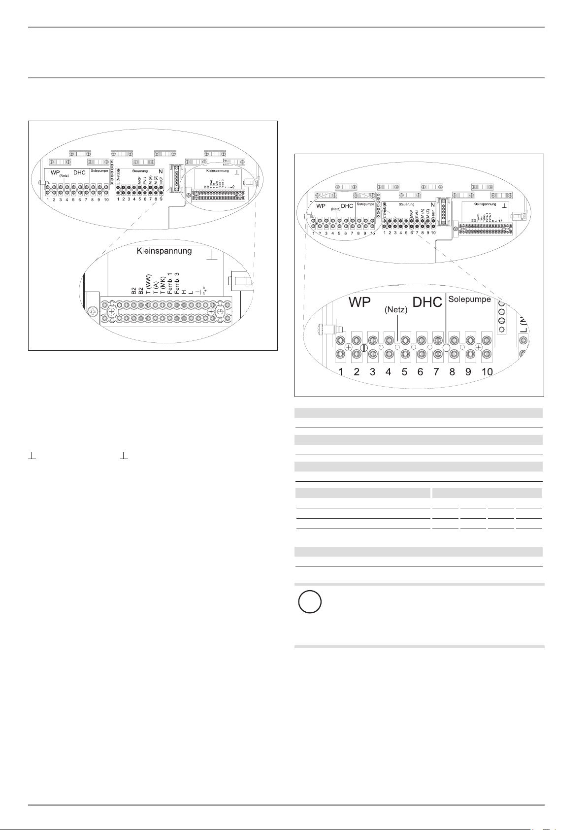
L1 L2 L3 N L1 L2 L3 L1’ L2’ L3’
ON
KS
Kühlen
B1
B1
1 2 3 4 5 6 7 8 9 10 11 12 13
B1 Temperature sensor heat pump flow
B2 Temperature sensor heat pump return
T (WW) DHW temperature sensor and earth
T(A) Outside temperature sensor and earth
T(MK) Mixer circuit temperature sensor and earth
Fernb. 1 Remote control 1
Fernb. 3 Remote control 3
H BUS high
L BUS low
BUS ground
“ + “ BUS “ + “
10.12.2 Electrical connection WPF S basic (single-phase)
Connection X3: Heat pump, electric booster heater and brine
pump
L N R RC L L’ N L N PE
26�03�01�1581
Heat pump power supply (compressor)
L, N, PE
Heat pump with WPAB power supply
R, RC, N, PE
DHC power supply (electric booster heater)
L, L´, N, PE
Connected load Terminal assignment
3.0 kW L N PE
3.2 kW L´ N PE
6.2 kW L L´ N PE
SONKS
Kühlen
B1
B1
1 2 3 4 5 6 7 8 9 10 11 12 13
26�03� 01�1611
Brine pump power supply
L, N, PE
Material losses
!
When a single phase brine pump is connected, protect
the heat pump and the DHC only via one common RCD.
If no electric emergency/booster heater is connected, N
must be tapped from X25 for the brine pump.
After connecting all electrical cables, refit and seal the cover over
the mains terminal strip.
26 | WPF basic www.stiebel-eltron.com
Page 27
INSTALLATION
S
ONKSKühlen
1 2 3 4 5 6 7 8 9 10 11 12 13
B1
B1
Mounting
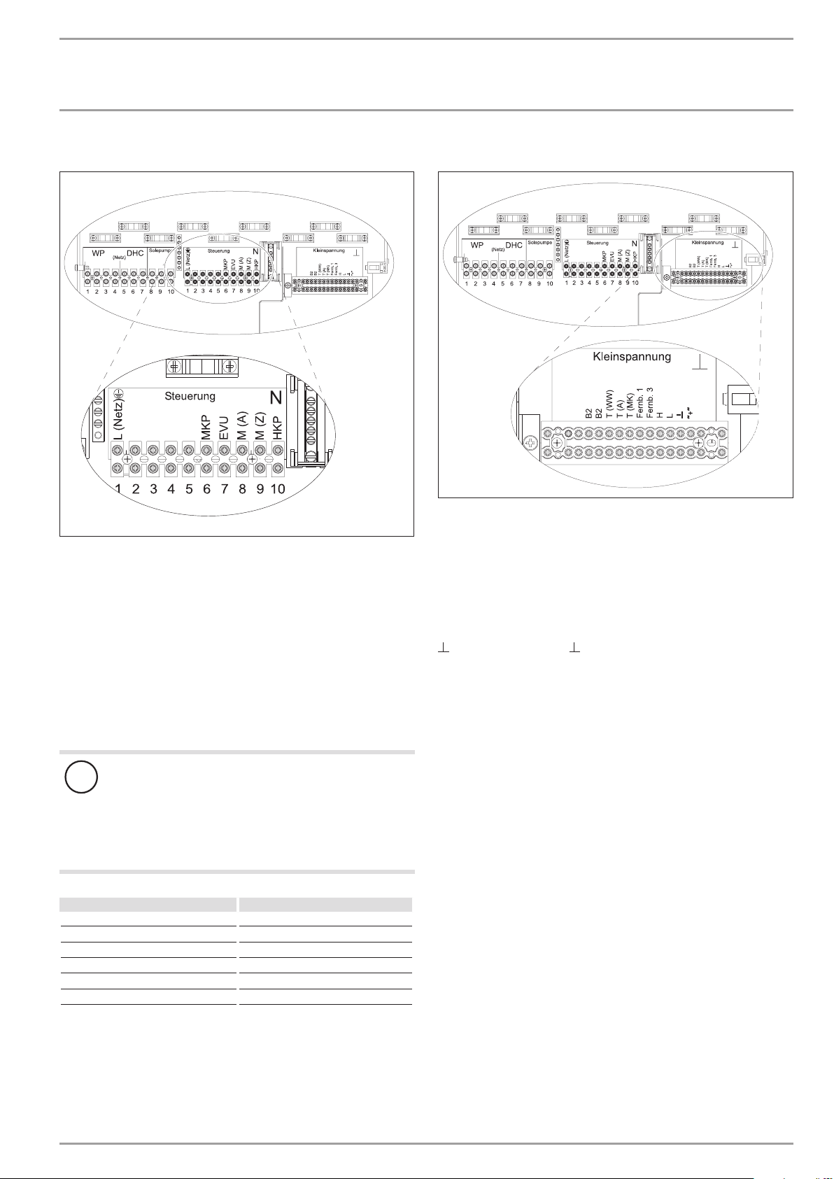
Connections X4: Control unit
L N R RC L L’ N L N PE
SONKS
Kühlen
Mains supply: L, N, PE
Outputs:
S Control output for the WPAB
ON Compressor signal
KS Brine pump signal
Cooling Cooling mode
MKP Mixer circuit pump and N, PE
Pump 2. Heating circuit and N, PE
M(A) Mixer open
M(Z) Mixer closed
HKP Heating circuit pump and N, PE
Control inputs:
EVU Power supply utility enable signal
B1
B1
1 2 3 4 5 6 7 8 9 10 11 12 13
Connections X2: Low voltage
L N R RC L L’ N L N PE
SONKS
Kühlen
B1 Temperature sensor heat pump flow
B2 Temperature sensor heat pump return
26�03�01�1612
T (WW) DHW temperature sensor and earth
T(A) Outside temperature sensor and earth
T(MK) Mixer circuit temperature sensor and earth
Fernb. 1 Remote control 1
Fernb. 3 Remote control 3
H BUS high
L BUS low
BUS ground
“ + “ BUS “ + “
B1
B1
1 2 3 4 5 6 7 8 9 10 11 12 13
26�03�01�1613
Material losses
!
Only connect energy efficient circulation pumps ap-
proved by us.
When using energy efficient circulation pumps not approved by us, an external relay with a breaking capacity
of at least 10A/250VAC or our relay set WPM-RBS is
required.
Part no.:
UP 25/7.0 E 232942
UP 25/7.5 E 232943
UP 25/7.5 PCV 235949
UP 30/7.5 E 2339 47
WPKI-HK E 233602
WPKI-HKM E 233603
www.stiebel-eltron.com WPF basic | 27
Page 28
INSTALLATION
Mounting
10.12.3 Electrical connection of WPF S basic (single phase) to
heat pump starting current limiter WPAB
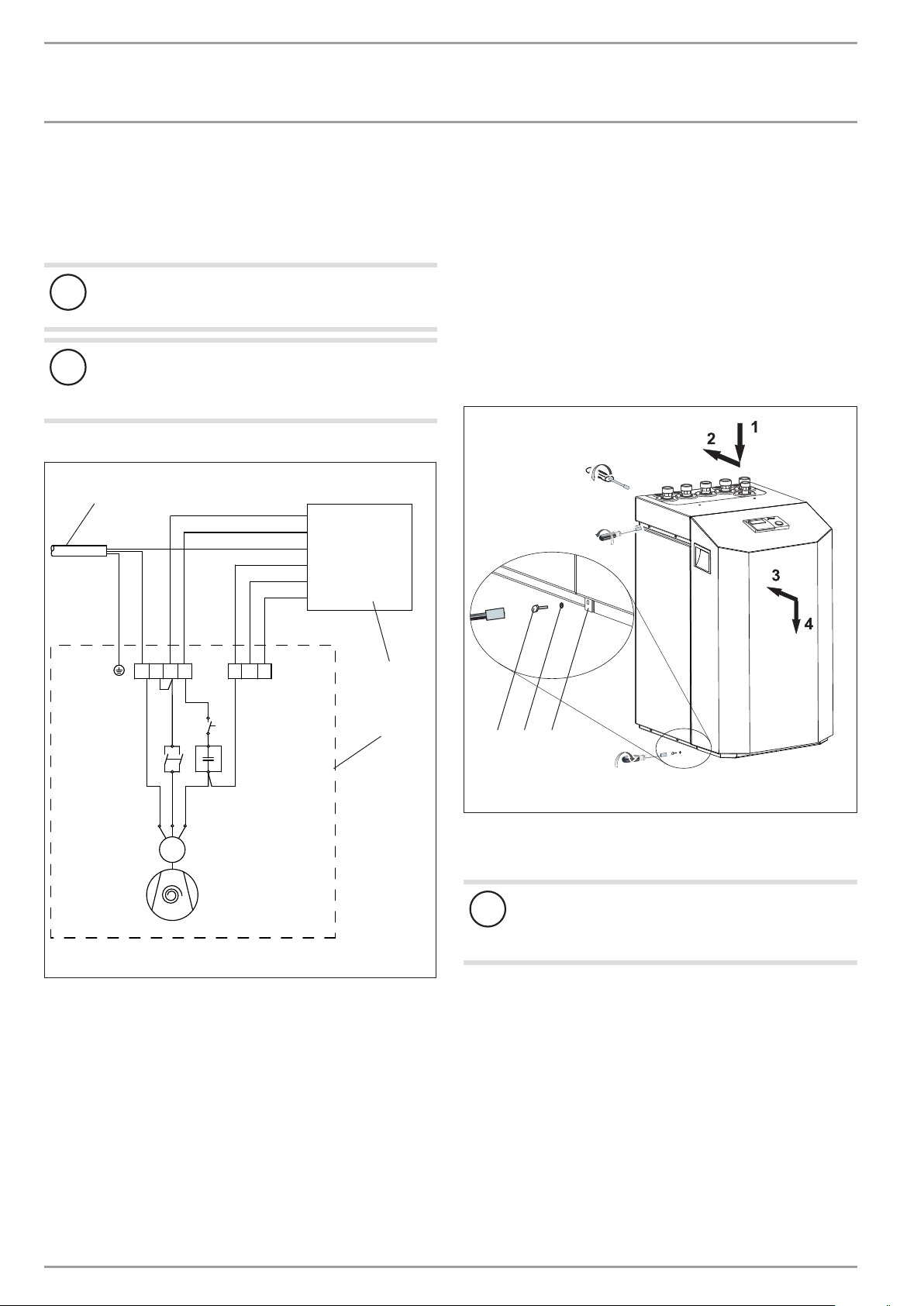
To limit the starting current of the WPF S basic, the WPAB can be
installed in the domestic distribution board. The WPAB limits the
starting current to the values listed in the specification.
Material losses
!
When a WPAB is connected to the heat pump, remove the
jumper between R and RC at terminal X3.
Material losses
!
When connecting a WPAB, use the same phase for L (terminal X3) of the compressor and L (terminal X4) of the
controller; protect the unit with an RCD.
Wire in accordance with the following diagram.
3
R
RC
L1
S
ON
N
10.13 Fitting the casing parts
When fitting the casing parts, please proceed as follows:
Close the cover of the control panel.
Secure the cover by firmly tightening the fixing screws with
serrated washers.
Fit the cover to the appliance.
After attaching the front cover, fix it to the side panels with
screws, as shown in the diagram. When attaching the front
cover, fit the tab with its screws and serrated washers. The
tab, screws and serrated washers can be found in the pack.
When attaching the front cover, ensure the earth conductor is
connected correctly.
2x
4x
X3
L R RCN
2 4
1
S P C
1~
X4
6
5
3
M
M1
1 WPAB
2 Heat pump
3 Power supply 1/N/PE 230V
NONS
1
2
3
1
2
2x
26�03�01�1575
1 Tab
2 Serrated washer
3 Screw
Appliance damage
!
The casing must stand on the floor free from the refrigeration unit. D. h. That means, the six plinth screws must
not be refitted.
26�03�01�0256
28 | WPF basic www.stiebel-eltron.com
Page 29
INSTALLATION
Mounting
10.14 installation
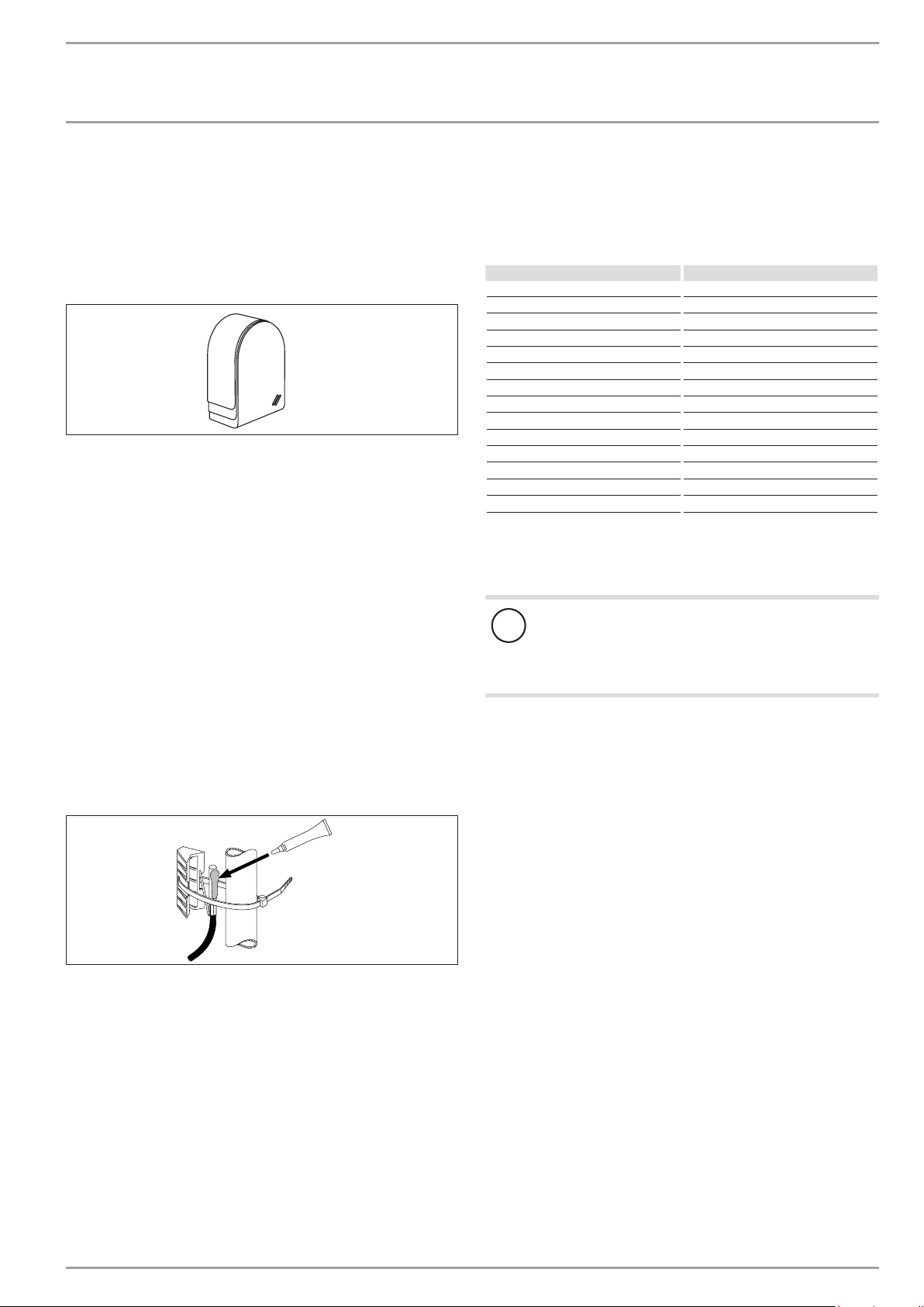
The temperature sensors have a decisive influence on the function
of your heating system. Therefore ensure the correct seating and
adequate insulation of sensors.
Outside temperature sensor AFS 2 (included in the pack
supplied)
Install the outside temperature sensor on a north or north-eastern
wall. Minimum distances: 2.5 m from the ground, 1 m to the side
of doors and windows. The outside temperature sensor should
be freely exposed to the elements, but should not be installed
above windows, doors or air ducts and should not be subject to
direct sunlight.
Connect the outside temperature sensor to terminal X2 (T(A)) and
the earth terminal block X26 of the appliance.
Installation:
Remove the cover.
Secure the lower part with the screw supplied.
Connect the cable.
Replace the cover. The cover must audibly click into place.
PTC sensor resistance values
The sensors installed in the appliance (return, flow and source
sensors), the outside temperature sensor AFS 2, the contact sensor AVF 6 and the PTC immersion sensor TF 6A all have identical
resistance values.
Temperature in °C Resistance in Ω
-20 1367
–10 1495
0 1630
10 1772
20 1922
25 2000
30 2080
40 2245
50 2417
26�03�21�0052
60 2597
70 2785
80 2980
90 3182
100 3392
10.15 High limit safety cut-out for underfloor heating
systems STB-FB
Material losses
!
In case of failure, in order to prevent an excessively high
flow temperature in the underfloor heating system, we
generally recommend the use of a safety temperature
controller to limit the system temperature.
Contact sensor AVF 6
This sensor is required when using a mixer circuit.
Installation information:
Clean the pipe.
Apply heat conducting paste.
Secure the sensor with a cable tie.
26�03�01�1431
www.stiebel-eltron.com WPF basic | 29
Page 30
INSTALLATION
Fernb.3
Fernb.1
Commissioning
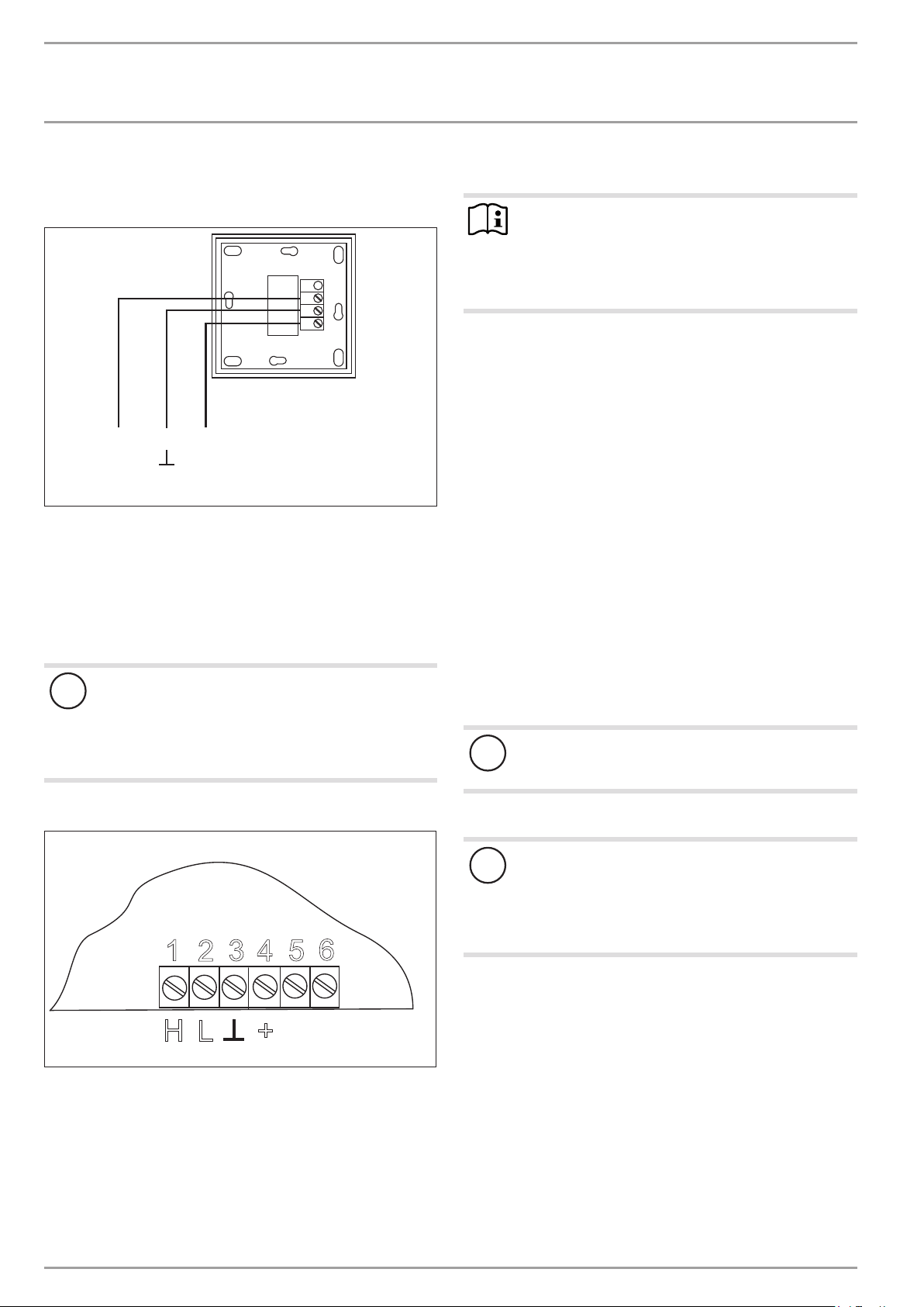
10.16 Remote control FE7
Connection array FE7
123
The FE 7 remote control enables you to adjust the set room temperature for heating circuit 1 or heating circuit 2 by ± 5 °C in
automatic mode only. You can also change the operating mode.
Connect it to the terminals Rem.con.1, and Rem.con.3 at terminal
block X2 and the earth terminal block X26 of the appliance.
10.17 Remote control FEK
11. Commissioning
Note
Does not apply to WPF5 (S) basic.
When quick start is used, the starting resistors are not
patched in.
Do not use quick start when measuring the starting
current.
Only heating contractors may carry out the adjustments on the
heat pump manager commissioning list, commission the appliance
and instruct the owner in its use.
Commissioning is to be carried out in accordance with these installation instructions and the operating and installation instructions
of the heat pump manager. Our customer service can assist in the
commissioning, which is chargeable.
Where this appliance is intended for commercial use, the rules of
the relevant Health & Safety at Work Act may be applicable
26�21�01�0008
for commissioning. For further details, check your local authorising body.
After commissioning, complete the commissioning report that are
part of these instructions.
11.1 Checks before commissioning
Before commissioning check the points detailed below.
Appliance and system damage
!
In cooling mode, the WPF requires the FEK for area cooling systems, e.g. underfloor heating systems, chilled
ceilings, etc. Apart from the room temperature, it also
determines the dew point temperature to prevent condensation.
Connection array FEK
2
L
3
4
+
1
H
The FEK remote control enables you to change the set room temperature for heating circuit 1 or heating circuit 2 by ± 5 °C as well
as the operating mode. Connect it to terminals H, L, I and + at the
terminal block X2 of the appliance.
5
6
11.1.1 Heating system
- Have you filled the heating system to the correct pressure,
and opened the quick-acting air vent valve?
System damage
!
Observe the maximum system temperature in underfloor
heating systems.
11.1.2 Heat source
System damage
!
With an underfloor heating system, never use the heat
pump to dry the screed as this places such a high demand
on the heat source that the frost protection function may
respond. See also chapter “Commissioning the heat pump
manager / Parameter HEAT-UP PROG”.)
11.1.3 High limit safety cut-out
At ambient temperatures below -15°C it may happen that the
high limit safety cut-out triggers the emergency/booster heater.
Check whether the high limit safety cut-out has responded.
26�03�01�0094
30 | WPF basic www.stiebel-eltron.com
Page 31
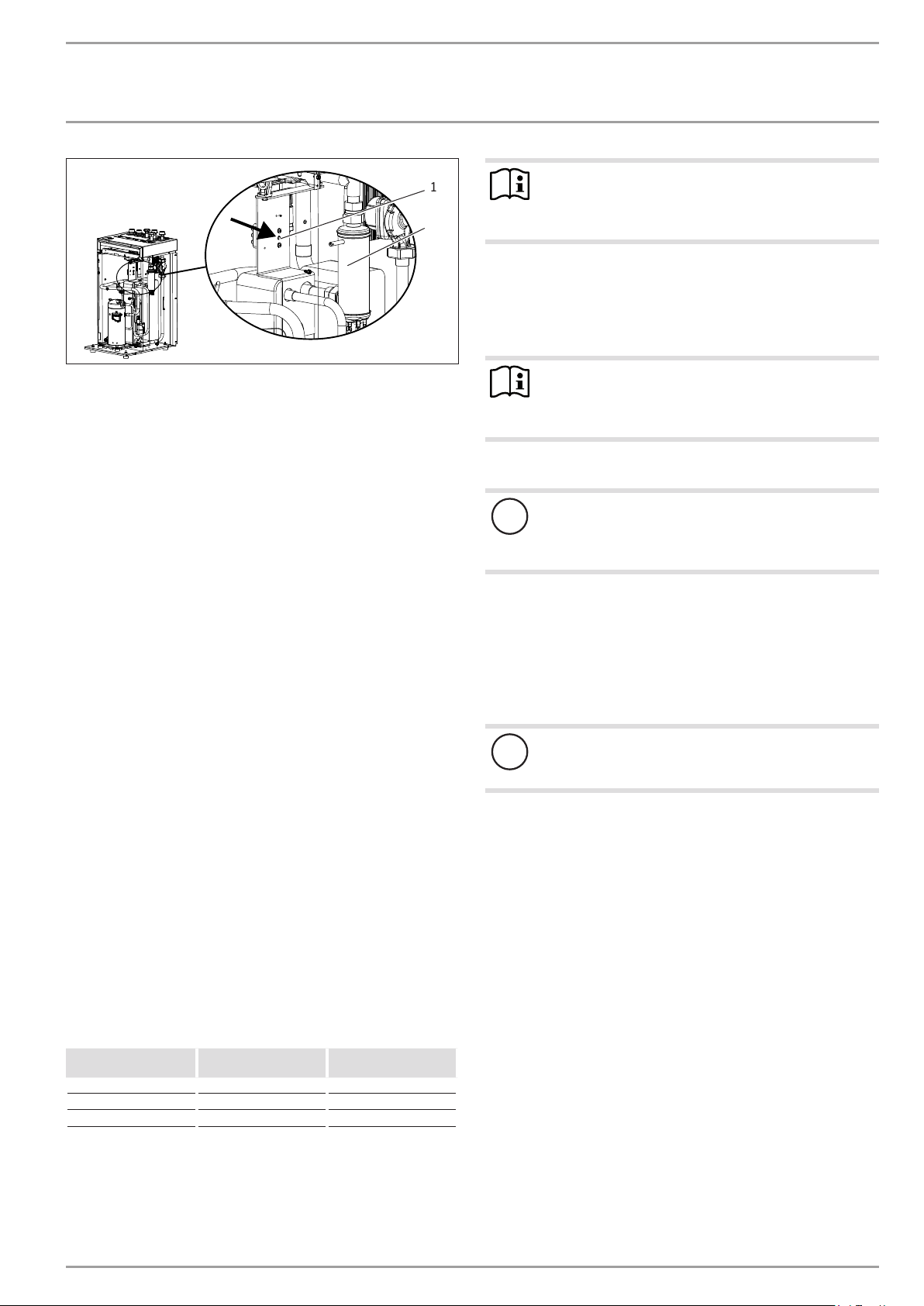
INSTALLATION
Commissioning
1
2
1 High limit safety cut-out reset button
2 Electric emergency/booster heater
Reset the high limit safety cut-out by pressing the reset
button.
11.1.4 Temperature sensor
- Have you correctly located and connected the outside temperature sensor and the return temperature sensor (in conjunction with a buffer cylinder)?
11.1.5 Power supply
- Have you correctly connected the power supply?
- The compressor turns in the right direction if, when voltage is applied to the heat pump power supply (mains), no
fault message appears in the display. If the fault message
NO OUTPUT appears, reverse the rotational direction of the
compressor.
11.2 Heating curve adjustment during
commissioning
The efficiency of a heat pump decreases with rising flow temperature. The heating curve should therefore be adjusted with care.
Heating curves that are adjusted too high lead to the zone and
thermostatic valves closing, which may lead to the minimum flow
rate required for the heating circuit not being achieved.
The following steps will help you to adjust the heating curve correctly:
- Fully open thermostatic or zone valves in a lead room (e.g.
living room or bathroom).
We do not recommend installing thermostatic or zone valves
in the lead room. Control the temperature for these rooms
via remote control.
- At different outside temperatures (e.g. -10 °C and +10 °C),
adjust the heating curve so the required temperature is set in
the lead room.
Standard values for a start:
Parameter Underfloor heating
system
Heating curve 0,4 0,8
Controller dynamics 5 15
Room temperature 20 °C 20 °C
Heating system with
radiators
Note
If no remote control is installed, raising the parameter
“room temperature” leads to a parallel offset of the heating curve.
Increase the parameter “HEATING CURVE” if the room temperature
is not high enough when outside temperatures are low.
If the parameter “Heating curve” has been raised, adjust the zone
or thermostatic valve in the lead room to the required temperature
at high outside temperatures.
26�03�01�1893
Note
Never reduce the temperature in the entire building by
closing all zone or thermostatic valves, but by using the
setback programs.
11.3 Operation and control
Appliance and system damage
!
Never interrupt the power supply outside the heating
period. The system‘s active frost protection is not guaranteed if the power supply is interrupted.
The system should not be switched off in summer. The heat pump
manager has an automatic summer / winter changeover.
11.4 Taking the appliance out of use
If the appliance is to be taken out of use, set the heat pump manager to standby. This retains the safety functions designed to protect
the system (e.g. frost protection).
Appliance and system damage
!
If the heat pump and frost protection are completely
switched off, drain the system on the water side.
If the room temperature in spring and autumn is too low (approx.
10 °C outside temperature), the parameter “Room temperature”
must be raised.
www.stiebel-eltron.com WPF basic | 31
Page 32
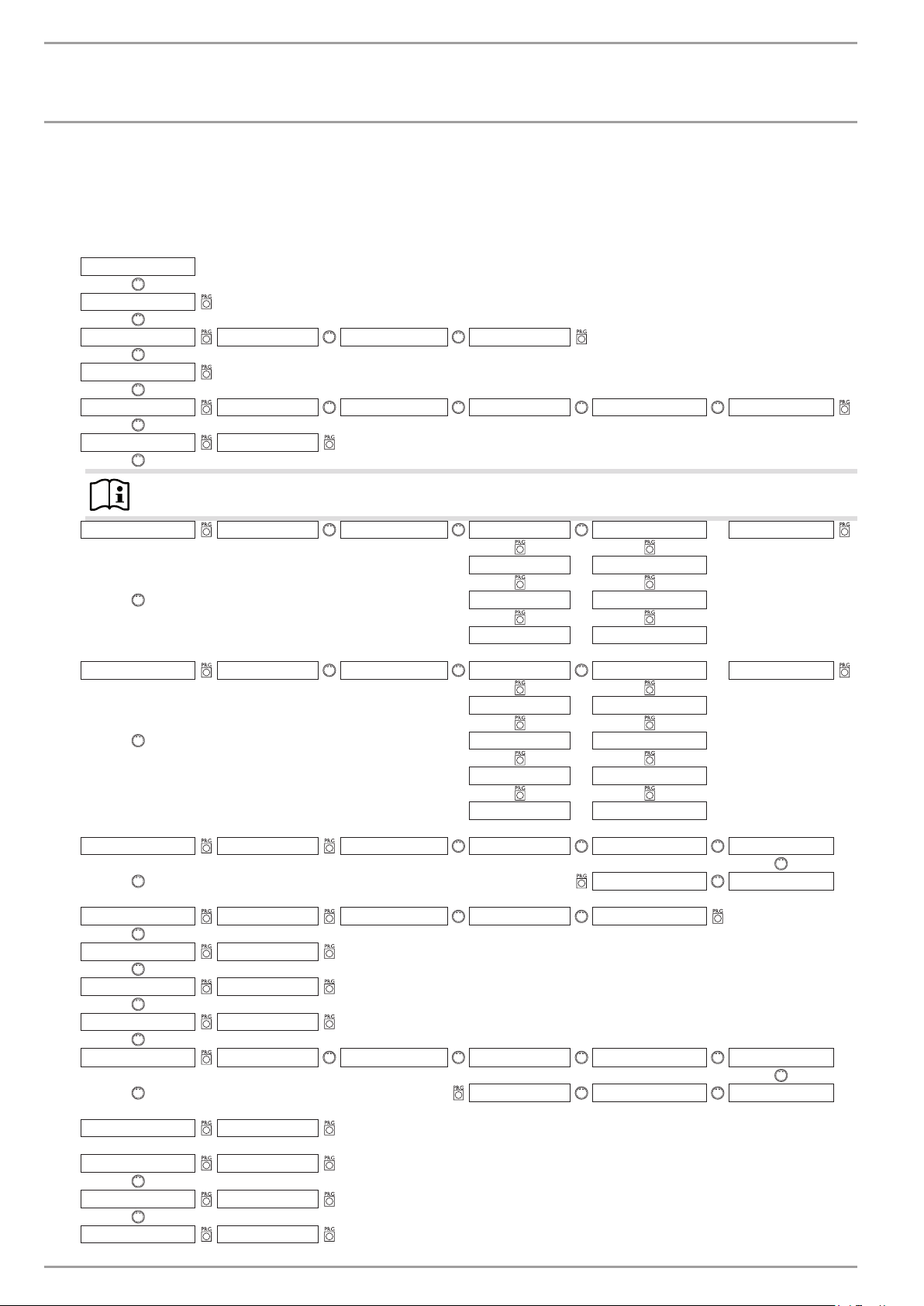
INSTALLATION
Commissioning
11.5 Heat pump manager commissioning summary
(Control level 3)
No. Parameter (shown in the display)
FIRST STARTUP
1
2
3
4
5
6
ENTER CODE
LANGUAGE GERMAN --- BACK
CONTRAST
DISPLAY ACTUAL RTRN T OUTSIDE TEMP DAY DHW TEMP MIXER TEMP
EMERG OPERTN ON / OFF
Note
The COOLING MODE parameter must only be set if there is a suitable hydraulic circuit.
COOLING OP ON / OFF PASSIVE FA N AREA BACK
COOLINGMODE
SET ROOM T SET ROOM T
SET FLOW TEMP SET FLOW TEMP
HYSTERESIS HYSTERESIS
ON / OFF ACTIVE FAN AREA BACK
SET ROOM T SET ROOM T
SET FLOW TEMP SET FLOW TEMP
HYSTERESIS HYSTERESIS
DYNAMIC DYNAMIC
HEAT-UP PROG ON / OFF LOW END TEMP LOW END DURAT MAX HEAT-UP T MAX HUT TIME
7
BACK INCREASE/DAY
SUMMER MODE ON / OFF BUILDING TYPE OUTSIDE TEMP BACK
8
PUMP CYCLES ON / OFF
9
BU PUMP CONST ON / OFF
10
11
12
13
14
15
FIXED VALUE OFF / °C
SOURCE ETHYLENE GLYCO
MIN SRCE TEMP °C
RETURN MAX °C
MAX HTG FLOW T °C
POTASS CARB
ALM 0 ALM 30 ALM 60
WATER ALM 180 ALM 120
16
32 | WPF basic www.stiebel-eltron.com
HP SENSOR BAR
Page 33
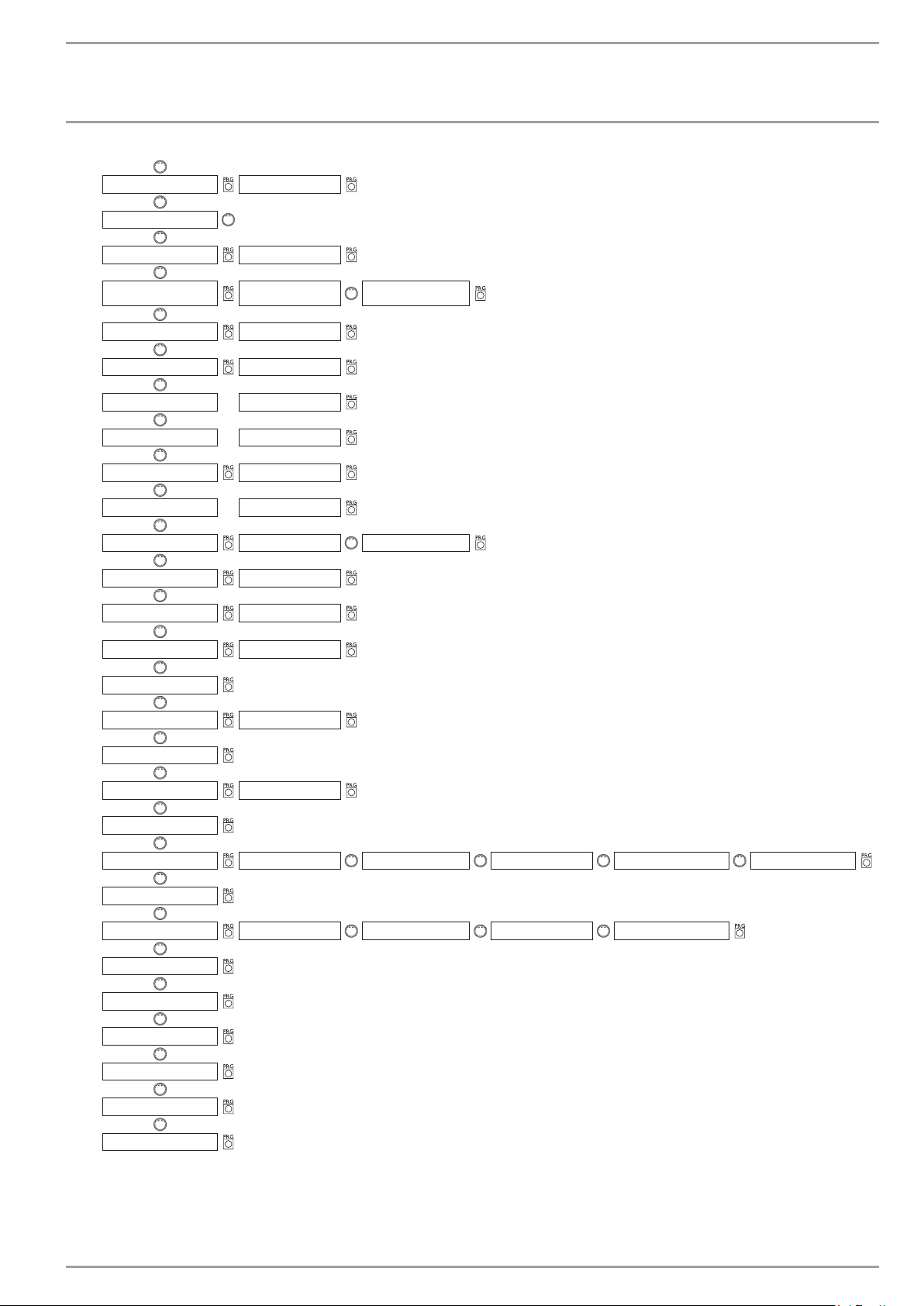
INSTALLATION
Commissioning
17
18
19
20
21
22
23
24
25
26
27
28
29
MIXER MA X °C
MIXER DYNAMIC
FROST PROTECT °C
SELECT REM CON
FE CORRECTION °C
ROOM INFLUENCE °C
HEATING LIMIT OFF / °C
DUAL-MODE HTG °C
DHW LIMIT °C
DUAL-MODE DHW °C
DHW ECO ON / OFF BACK
DHW HYSTERESIS °C
DHW CORRECTION °C
HEATING CIR-
CUIT 1
HEATING CIRCUIT 2
PASTEURISATION ON / OFF
30
CNTRL DYNAMIC
31
32
33
34
35
36
37
38
39
40
41
42
IDLE TIME MIN
REM IDLE TIME
SINGLE PHASE ON / OFF
QUICK START
RELAY TEST DHW PRIM PUMP RELAY TEST IWS ----- BRINE PUMP BACK
LCD TEST
FAULT LIST FAULT 1 --- FAULT 20 BACK
WPMIW SOFTWARE
ANALYSIS
DIAGNOSIS
HEAT P RESET
43
www.stiebel-eltron.com WPF basic | 33
RUNTIMES
BACK
Page 34
INSTALLATION
Commissioning
11.6 Heat pump manager commissioning
General information
Not only the adjustments at control level 2 but also the system-specific parameters must be determined as part of commissioning the
heat pump system. These parameters are adjusted at control level
3, access to which is protected by code.
Note
The heat pump manager should be in standby mode during commissioning. This prevents an uncontrolled heat
pump start. Please remember to reset the system into its
last operating mode.
Check all parameters in sequence, and enter all selected values
into the column (system value) provided in the commissioning
report.
Note
Not all adjustments take immediate effect. Some adjustments only become effective in certain situations or after
a delay.
1 CODE
Enter the correct four-digit code to change parameters at control
level 3. The factory-set code is 1 0 0 0.
After pressing PRG (indicator illuminates), the first digit can be
selected by turning the rotary selector. Pressing PRG again confirms the value, then the second digit of the code begins to flash.
Turning the rotary selector enables the second digit of the code to
be entered, etc. When all four digits have been entered correctly,
four lines appear in the display. This enables access to control
level 3, and the display shows CODE OK. Closing and re-opening
the flap requires that the code is entered again. Checking settings
does not require the code to be entered.
2 LANGUAGE
Here you can select the menu language.
Press PRG.
Select required language.
Confirm with PRG.
5 EMERGENCY MODE
Characteristics in case of “Fatal Error” conditions in conjunction
with the emergency operation:
The EMERGENCY MODE parameter can be set to ON or OFF.
Emergency mode set ON:
The program selector automatically changes over to emergency
mode as soon as faults occur and the heat pump fails.
Emergency mode set OFF:
The booster heater takes over the frost protection of the central
heating system, as soon as faults occur and the heat pump fails.
Users can then select emergency mode on their own initiative.
6 COOLING MODE
WPF 5 - 16
This equipment is designed for DHW and central heating. In the
delivered condition, the COOLING MODE parameter is set to OFF.
Cooling mode is only possible in conjunction with a suitable hydraulic circuit.
Appliance and system damage
!
The COOLING MODE parameter must only be set if there
is a suitable hydraulic circuit.
Note
The COOLING MODE parameter will only be shown if a FEK
or FE7 remote control is connected. The cooling mode is
only possible in summer.
The WPF with a suitable circuit cools in 2 stages:
Stage 1 (source pump)
Heat is extracted from the heating circuit and is passed to the
heat source system.
Stage 2 (source pump + compressor)
In addition, the cooling circuit extracts heat from the heating circuit and transfers it to the heat source system.
3 CONTRAST
The display contrast can be adjusted here.
Use the rotary selector to adjust the contrast.
4 DISPLAY
Select, what will be displayed when the programming unit flap is
closed. The options are:
- outside temperature,
- return temperature,
- day and time,
- DHW temperature or
- mixer temperature.
34 | WPF basic www.stiebel-eltron.com
DHW heating
DHW heating always has priority. As long as the actual temperature has not dropped below the set flow and room temperature, active cooling continues even during DHW heating, and any
extracted heat is transferred to the DHW. If there is no cooling
demand, DHW is conventionally heated via the heat source system.
Cooling operation with the FE 7
The FE7 is not equipped with dew point monitoring. It can therefore only be used in conjunction with fan convectors with condensate drain. Set the cooling mode to FAN.
Cooling operation with the FEK
The FEK remote control is equipped with dew point monitoring,
and can therefore be used with area heating systems (e.g. underfloor/wall heating systems, etc.). Set parameter 6 to AREA. The
Page 35
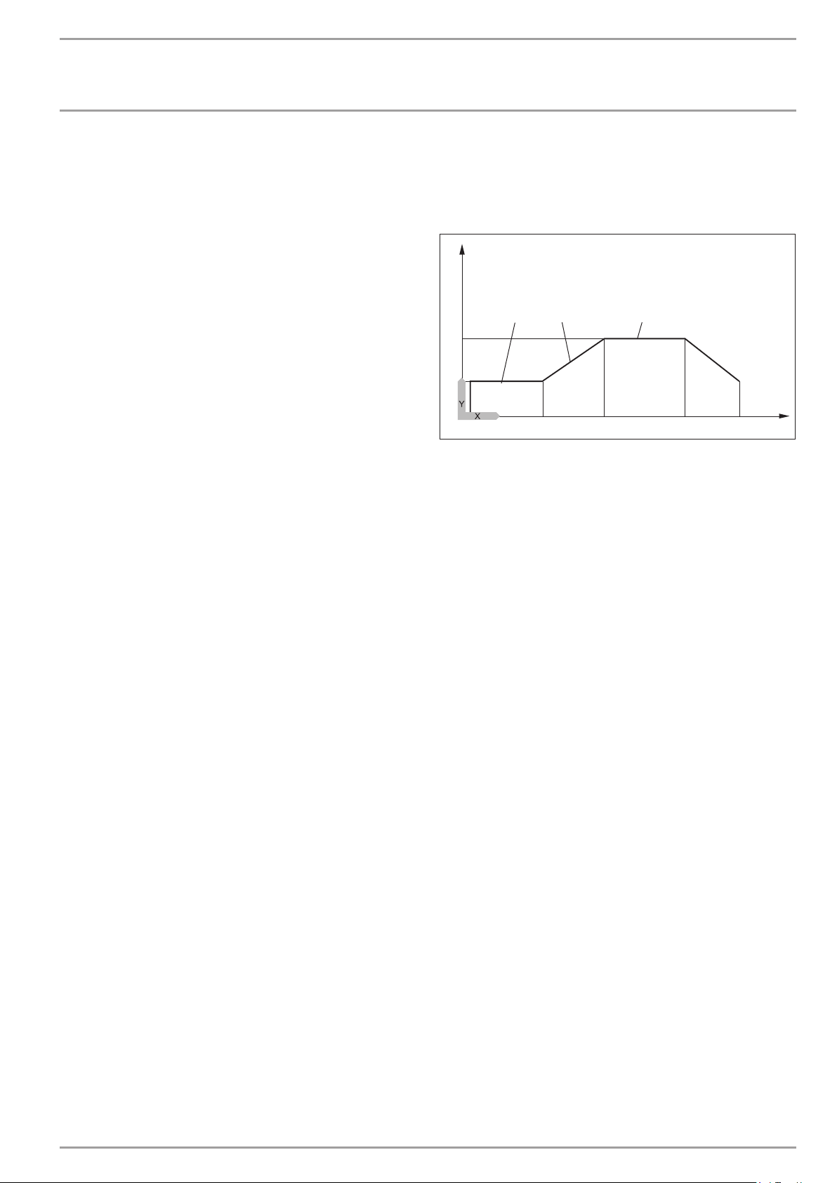
INSTALLATION
Commissioning
set flow temperature is compared with the captured dew point
temperature, so the actual temperature never drops below the
dew point. When using fan convectors with the FEK remote control,
set the COOLING MODE parameter to FAN.
The following settings for the FE 7 and the FEK can be selected for
the cooling operation in parameter 6:
- Room temperature
Cooling starts when the selected room temperature is exceeded (output COOLING=230 V).
Cooling is stopped, if the actual room temperature drops 2 K
below its set temperature. (output COOLING=0 V)
- Flow temperature and hysteresis
The cooling operation is regulated via the selected flow temperature. The brine pump starts at:
[flow temperature + hysteresis]
Brine pump off, when the actual temperature drops below
the flow temperature.
The [flow temperature+hysteresis] should be at least 3 K <
room temperature. Lower flow temperatures cause a more
rapid cooling of the room.
As soon as, with setting AREA, the determined dew point
temperature is + 2 K higher than the selected flow temperature, that temperature will be overridden with the dew point
temperature and acts as controlled variable. The brine pump
starts at [entered or newly determined flow temp. + hysteresis].
The source pump stops and the cooling operation terminates, if the actual flow temperature lies below the entered
or newly determined flow temperature. The cooling signal
remains active.
- Dynamic
Dynamics can be adjusted from 1 to 10. It describes the delay
between stage 1 and stage 2, whereby the second stage is
started sooner, the smaller the value.
7 HEAT-UP PROG
Heat-up program for underfloor heating systems
Never use the heat pump to dry the screed as this places such a
high demand on the heat source that the frost protection function
may respond. The electric emergency/booster heater must be used
for the heat-up program. For this, set parameters HEATING LIMIT
and DUAL-MODE HTG to 30°C and start the heat-up program.
Emergency mode cannot be enabled in the heat-up program.
There are a total of 6 parameters for the heat-up program. These
6 parameters can be adjusted in sequence as soon as the heat-up
program is activated. This program is started with the parameter
HEAT-UP PROG and with the setting ON. The system then heats
to the selected low end temperature (parameter LOW END TEMP).
The low end temperature is then held for the set period (parameter
LOW END DURAT). After expiry of this period, the system heats
with an increase K/day (parameter INCREASE/DAY) to the maximum low end temperature (parameter MAX. HEAT-UP T) and is
held at the maximum temperature via the selected time (parameter MAX T DURATION). After expiry of this period, the system
reduces the temperature back to the low end temperature in the
same stages as per heat-up. This concludes the heat-up program.
As soon as two heating circuits are operational, both will be operated in accordance with this heat-up program (operation with
buffer cylinder and mixer circuit). Direct heating circuit 1 (buffer
circuit with return sensor) adopts the heat-up program’s set val-
ues. The actual temperature inside the buffer cylinder is higher
at the heating flow, since it is regulated via the return sensor. The
mixer (heating circuit 2) regulates the temperature back down to
the selected set values in the heat-up program (low end temperature and maximum temperature).
3
1
2
6
Y Temperature
X Time
1 Maximum temperature
2 Low end temperature
3 Low end temperature rise period
4 Increase K/day
5 Maximum temperature duration
6 Start
7 End
Please note that only the mixer circuit pump is running when
operating with two heating circuits.
The return sensor is again used for control, when only the direct
heating circuit 1 is operational. As the actual temperature inside
the buffer cylinder is higher at the heating flow, this constellation
sees 5 K being deducted from the set heat-up program values (low
end and maximum temperatures).
The summer logic is disabled whilst the heat-up program runs
4 5
7
8 SUMMER MODE
The summer mode parameter allows you to select the time from
when the heating system should change into summer mode. Summer mode can be switched ON or OFF. This function offers two
adjustable parameters.
The “Building Type” parameter determines, subject to building
type (setting 1, 2 or 3), an adjusted outside temperature. If the
calculated outside temperature ≥ the selected outside temperature, both heating circuits (if installed) switch to summer mode;
reset hysteresis –1 K. SUMMER MODE is shown in the display when
the flap is closed.
With set-value control, summer mode is disabled for heating circuit 1.
OUTSIDE TEMP parameter:
Available outside temperature 10 °C to 30 °C
BUILDNG TYPE parameter:
Setting 1: Mild adjustment of the outside temperature (averaging over a 24 h period), e.g. timber construction with rapid heat
transfer.
84�03�01�0038
www.stiebel-eltron.com WPF basic | 35
Page 36
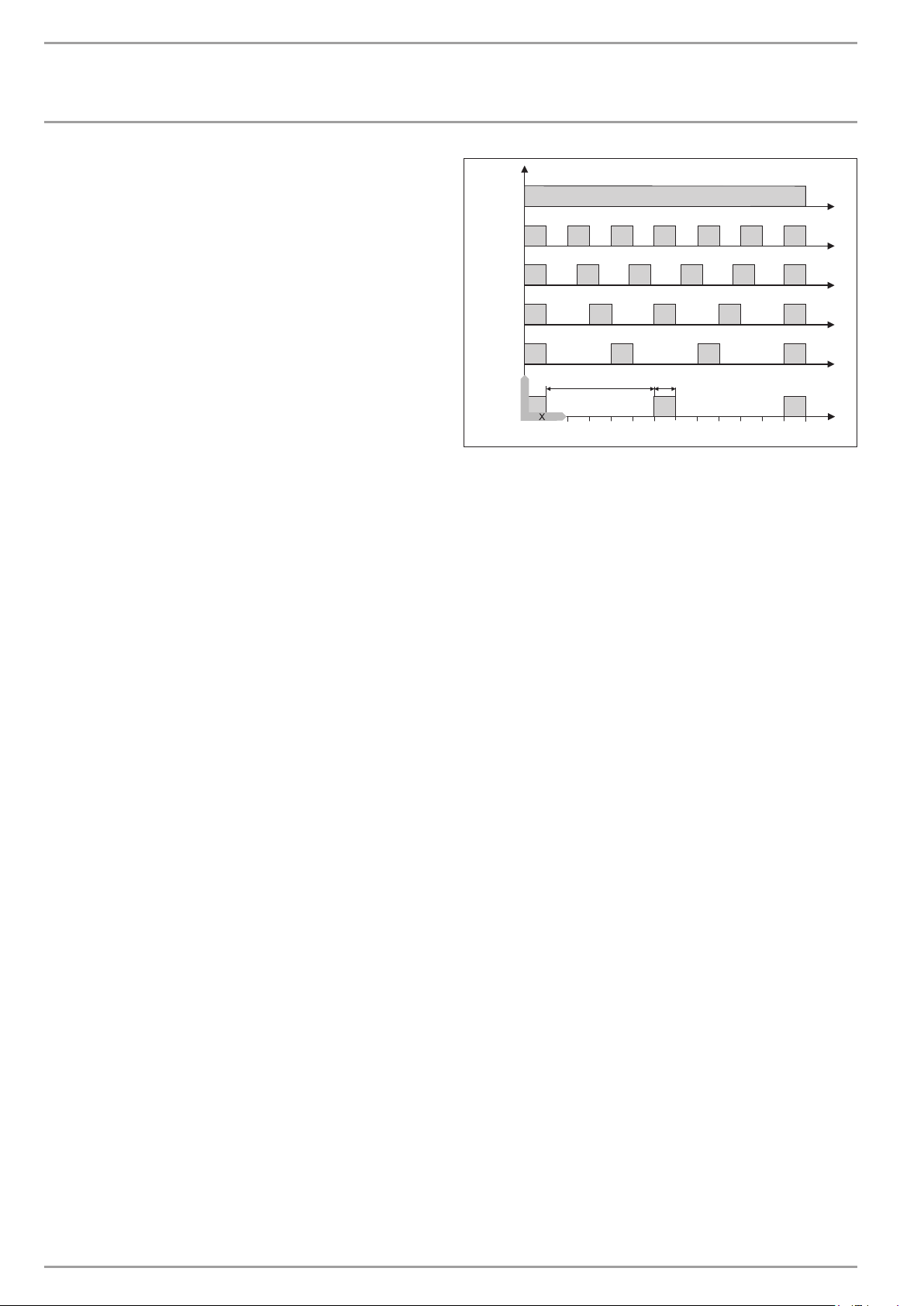
INSTALLATION
Commissioning
Setting 2: Moderate adjustment of the outside temperature (averaging over a 48 h period), e.g. solid construction with thermal
insulation and average heat transfer.
Setting 3: Severe adjustment (averaging over a 72 h period) of the
outside temperature, e.g. house with slow heat transfer.
< -10
-10
9 PUMP CYCLES
Heating circuit pump control
The PUMP CYCLES parameter only applies to the direct heating
circuit 1, i.e. for heating circuit pump 1.
This parameter can be set ON or OFF . In setting OFF the heating
circuit pump will not cycle. Instead, it will operate constantly and
is only switched off in summer mode.
The heating circuit pump start will be controlled in accordance
with a fixed temperature curve of the outside temperature, as soon
as this parameter is set to ON.
The heating circuit pump start pulse is always five minutes.
The heating circuit pump for heating circuit 1 always starts with
each heat pump start. The pump runs on for 5 minutes after the
heat pump has been switched OFF. Now the start-up duration is
brought to bear, e.g. at an outside temperature of 5 °C, the pump
starts three times per hour for five minutes respectively.
Pump kick
To prevent the pumps seizing up, over the summer for example,
when a pump has been switched off for 24 hours it will be switched
back on for 10 seconds. This applies to all pumps.
Heating circuit pump control with connected FE7/FEK remote
control
In conjunction with the FE7 or FEK remote control, the respective heating circuit pump is switched off and the mixer moves to
“Closed” in accordance with the switching condition
ϕ
ACTUAL room >ϕSET room
the respective heating circuit pump is switched OFF and the mixer
moves to “CLOSE”. This only applies if the room sensor influence is
set to K > 0. Reverse control is subject to the following condition:
ϕ
ACTUAL room >ϕSET room
The summer mode also becomes effective for the respective heating circuit when operating with a FE7 or FEK remote control.
+ 1 K
-5
0
5
Y
10
0 10 20 30 40 50 60
1
2
Y Outside temperature in °C
X Time in minutes
1 Pause
2 Pump run time
10 BU PUMP CONST
When using a buffer cylinder, set this parameter to OFF.
11 FIXED VALUE
Fixed value temperature
The heat pump return is controlled at the set fixed value. The
switching time program will then be ignored. The various program
switch positions will then only affect the mixer circuit (if installed).
The frost protection is activated and the compressor is switched
OFF when the program selector is set to “Standby” and a fixed
temperature has been selected. Summer logic remains disabled
with fixed temperature control. This means that the heating circuit
pump is not switched off for the direct heating circuit. With the
flap closed, the display shows the fixed temperature program, in
other words always showing the heating times.
12 SOURCE
Frost protection for brine|water heat pumps
The heat pump can only be operated as ground source heat pump.
Ethylene glycol as brine (including polypropylene glycol) means
that the heat pump frost protection is inactive. Responses by the
frost stat no longer have any influence.
Potassium carbonate as brine (STIEBEL ELTRON heat transfer medium) means that the heat pump frost protection is inactive. This ensures that the source pump is started at an
outside temperature of -10°C, even if the heat pump is idle.
It is switched OFF again at an outside temperature of – 8 °C.
ALM 0, 30, 60, 120 and 180
(Only in conjunction with the extractor module LWM 250)
At a brine inlet temperature of < 10 °C, a regeneration of the heat
source system can be implemented in conjunction with the extractor module and ethylene glycol or propylene glycol as brine.
Settings enable the determination of the run-on time of
the brine pump, after the heat pump has been shut down.
The values stated correspond to the run-on time in minutes at an
average brine inlet temperature of 0 °C.
84�03�01�0039
36 | WPF basic www.stiebel-eltron.com
Page 37
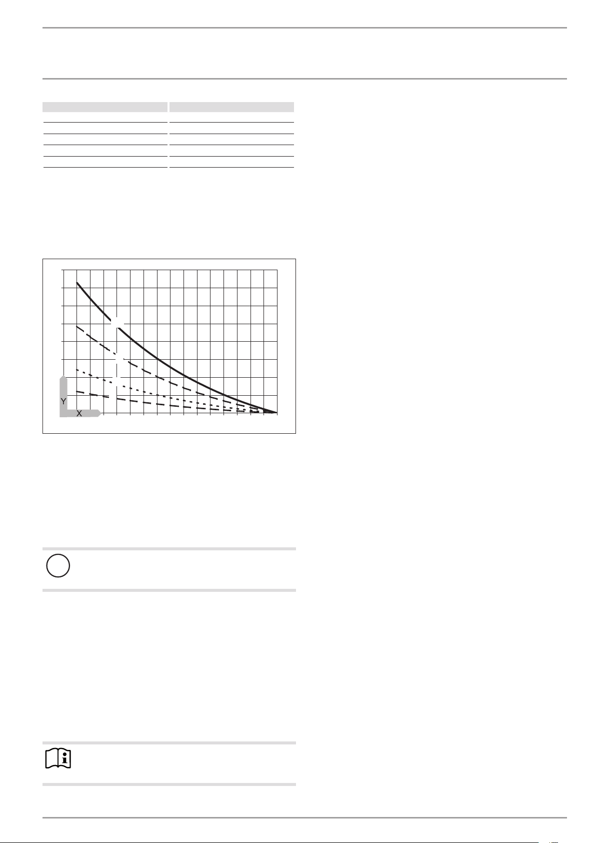
INSTALLATION
Commissioning
Sett ing Brine pump run-on time
ALM 0 1 minute
ALM 30 30 minutes
ALM 60 60 minutes
ALM 120 120 minutes
ALM 180 180 minutes
If the brine inlet temperature rises, the resulting run-on time of the
source pump reduces accordingly. If the brine inlet temperature
drops, the run-on time increases. From a brine inlet temperature
of 10 °C, the run-on time will always be at least one minute.
Brine pump run-on time with extractor module
400
350
300
250
200
150
100
50
0
-6 -5 -4 -3 -2 -1 0123 4567 8 9 10
Y Brine pump run-on time [minutes]
X Brine inlet temperature [°C]
1 ALM 30
2 ALM 60
3 ALM 120
4 ALM 180
1
2
3
4
13 MIN SRCE TEMP
Setting range -10 °C to +10 °C and setting OFF.
Appliance and system damage
!
Never operate the appliance with source temperatures
below – 9 °C.
In the OFF position there is no scanning via the source sensor
temperature.
The compressor shuts down and the idle time is set, when the actual temperature drops below the minimum source temperature.
The compressor is enabled again after the idle time has expired
and the fixed hysteresis of 2 K has been exceeded.
This fault, i.e. MIN SRCE TEMP, will be indicated in the display by
a flashing warning triangle, and will be entered into the fault list.
The source pump will always be started 30 seconds earlier than
the compressor, which starts when there is a heat demand coming
from the central heating or DHW side.
Note
The source pump runs on for 60 minutes after the heat
pump has been switched OFF.
14 RETURN MAX
Maximum return temperature
Setting range 20 °C to 55 °C
If the temperature at the return sensor reaches this value during
heating operation, the heat pump is switched OFF immediately.
This safety function prevents the high pressure limiter responding.
No fault message is triggered when this value is reached.
The return temperature is not scanned during DHW operation.
15 MAX HTG FLOW T
Maximum heat pump flow temperature for central heating
Setting range 20 °C to 65 °C
This setting limits the flow temperature of the heat pump and the
electric booster heater during the heating operation.
16 HP SENSOR
Maximum high pressure
Setting range 38 bar to 40 bar.
This setting limits the high pressure during DHW or central heating. The system implements a controlled shutdown when the
maximum high pressure is reached.
See also DHW ECO.
84�03�01�0016
17 MIXER MAX
Maximum mixer flow temperature
Setting range 20 °C to 90 °C
This setting limits the mixer circuit’s flow temperature. For example, if a higher set flow temperature is calculated from the mixer
circuit data, the max. set mixer flow temperature will be used to
control and regulate to this value.
18 MIXER DYNAMIC
Mixer runtime
Setting range 60 to 240
This setting can be used to adapt the mixer characteristics. The
setting 60 to 240 means 6 K to 24 K control deviation.
The system scans every 10 s, and the minimum ON time for the
mixer is 0.5 s. The mixer does not respond inside the dead zone
of ±1 K from the set value.
Example for the setting 100 = 10 K
The control deviation (set mixer temperature – actual mixer temperature) is 5 K. The mixer opens for 5 s, then pauses for 5 s and
starts again from the beginning.
The control deviation (set mixer temperature – actual mixer temperature) is 7.5 K. The mixer opens for 7.5 s, then pauses for 2.5 s
and starts again from the beginning.
The smaller the control deviation, the shorter the mixer ON time
and the longer its pauses.
A reduction of the MIXER DYNAMIC value with static control deviation increases the ON duration and reduces pauses.
www.stiebel-eltron.com WPF basic | 37
Page 38
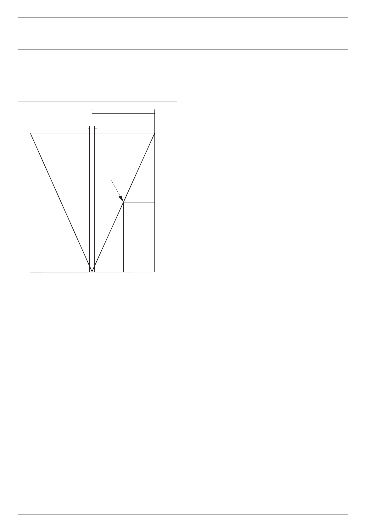
INSTALLATION
Commissioning
Example of setting 100 and a current control deviation of 5 K.
5 K of 10 K = 50% = ON duration
Example of a control deviation
1
± 1 K
2
4
3
1 Setting 100 = control deviation 10 K
2 Control deviation 5 K
3 Control deviation in K
4 ON time in %
19 FROST PROTECT
The heating circuit pumps are started at the selected frost protection temperature, to prevent the heating system being damaged
by frost; the reverse hysteresis is 1 K.
20 SELECT REM CON
Remote control FE7 can be selected for both heating circuits
The SELECT REM CON parameter can be used to preselect the heating circuit with which the remote control is to be used. Under the
parameter ROOM T 1 OR 2 at control level 2, you can scan the actual room temperature, subject to the remote control preselection.
21 FE CORRECTION
This parameter enables the calibration of the actual room temperature.
22 ROOM INFLUENCE
Room influence for the FE 7 remote control unit
Standard setting 5 adjustable from ----via 0 to 20 dashes (----)
in the display:
With the FE7 remote control connected, the room temperature
sensor only serves to record and display the actual room temperature; it has no influence on the actual control. Only in automatic
mode can the room temperature for heating circuit 1 or 2 be
adjusted by ± 5 °C. This set value adjustment applies to the then
current heating time, not to the setback time.
At the same time, setting “0 to 20” serves to control the room temperature-dependent night setback. This means that the heating
circuit pump is switched OFF at the point of changeover from the
heating into the setback phase. It remains OFF, until the actual
room temperature falls below the set room temperature. Afterwards, the system regulates in weather-compensated mode.
If you want the room temperature to be taken into account, set
the room temperature sensor influence to > 0. The room sensor
influence has the same effect as the outside temperature sensor
has on the return temperature, only this effect is 1 to 20 times
greater by the set factor.
Room temperature-dependent return/flow temperature with
weather compensation
With this type of control, a control cascade is formed from a return/flow temperature control that is subject to both weather and
C26�03�01�1067
room temperature. Consequently the weather-compensated return/flow temperature control sets a default return/flow temperature that is corrected by the overriding room temperature control
in accordance with the following formula:
= (ϕ
∆ϕ
R
Because a substantial proportion of the control is already handled
by the weather-compensated control unit, the room temperature
sensor compensation factor K can be set lower than with pure
room temperature control (K = 20). The figure below indicates
the control method with the set factor K=10 (room influence) and
a heating curve S=1.2.
Room temperature control with weather-compensation
This type of control offers two main benefits:
Incorrectly set heating curves are corrected by the room sensor influence K; whilst the smaller factor K provides more stable control.
However, observe the following for all control units with room
temperature sensor influence:
- The room temperature sensor must capture the room temperature accurately.
- Open doors and windows greatly affect the control result.
- All radiator valves in the lead room must be fully open at all
times.
- The temperature inside the lead room is the one which affects the entire heating circuit.
If you want the room temperature to be taken into account, set
the room temperature sensor influence to > 0.
RSET
− ϕ
RACTUAL
) * S * K
38 | WPF basic www.stiebel-eltron.com
Page 39
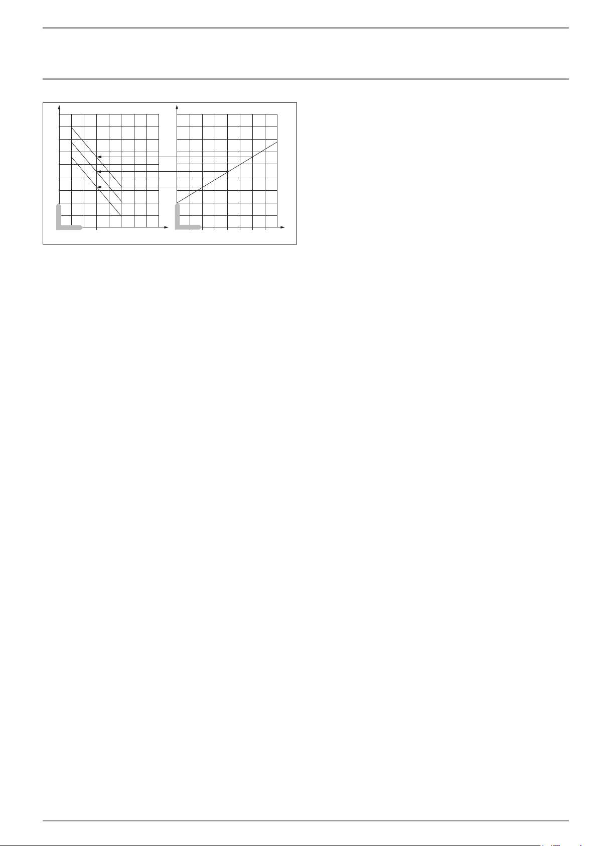
INSTALLATION
Commissioning
90
80
70
1
60
1
50
1
40
30
20
10
Y
0
X 1
20
1917 18 21 22 23 24 25
3
4
5
Y
X 2
10
15
20
2
-10
-5
0
5
-20
-15
Y Flow temperature [°C]
X 1 Room temperature [°C]
X 2 Outside temperature [°C]
1 Room temperature sensor influence at K = 10 and S = 1.2
and control deviation +/- 2 K
2 Heating curve S = 1.2
3 Weather-compensated set flow temperature at ϕA = -10 °C
4 Weather-compensated set flow temperature at ϕA = 0 °C
5 Weather-compensated set flow temperature at ϕA =
+10°C
23 HEATING LIMIT
Heat pump application limit
The heat pump is switched off if the outside temperature drops
below the selected lower application limit for heating.
Only the electric booster heater provides central heating.
24 DUAL-MODE HTG
The dual-mode temperature of the heat pump for heating operation
Below this outside temperature, the electric booster heater is
added for central heating, subject to load.
25 DHW LIMIT
Heat pump application limit
The heat pump is switched off at outside temperatures below the
selected lower DHW application limit.
Only the electric booster heater provides DHW heating.
26 DUAL-MODE DHW
The dual-mode temperature of the heat pump for DHW operation
Below this outside temperature, the electric booster heater is
added for DHW heating, subject to load.
27 DHW ECO
temperature of 70 °C is achieved in this operating mode, DHW
heating will be terminated, and the set DHW temperature is overwritten with the actual DHW temperature.
Setting ON
DHW heating will be terminated and the set DHW temperature is
overwritten with the actual DHW temperature, as soon as the heat
pump is shut down in DHW mode via the high pressure sensor or
via the hot gas temperature limit (130 °C). This operating mode
saves energy, as DHW is exclusively heated by heat pump.
28 DHW HYSTERESIS
26�03�01�1917
This determines the switching hysteresis for DHW operation.
- Starting DHW heating at the set DHW temperature minus the
hysteresis value.
29 DHW CORRECTION
The DHW temperature is measured in the bottom third of the
cylinder. The DHW outlet temperature is approx. 3K higher than
the measured temperature. This deviation is corrected and can be
calibrated, if required.
30 PASTEURISATION
The DHW cylinder is heated daily at 01:00 h to 60 °C, if pasteurisation has been enabled. Pasteurisation can only be achieved with
the heat pump and direct electric heating (internal DHC stages).
31 CNTRL DYNAMIC
Setting range 0 to 30
The selected control dynamic is a measure of the switching interval
between the compressor and the booster heating stages. Normally, the selected response time should be sufficiently fast and
without oscillation. Heating systems that respond quickly require
a lower value, whilst very slow responding systems require you
to set a higher value.
32 COMP IDLE TIME
After a heat pump has been switched OFF, an idle time is set as
protection for the compressor. The default idle time of 20 minutes
should normally not be reduced. Where a reduction is required
because of adjustments or repair work, reset the idle time again
to 20 minutes after completing the necessary work.
33 REM IDLE TIME
Remaining idle time
Pressing PRG enables you to scan the compressor idle time.
34 SINGLE PHASE
This parameter must always be set to ON for single phase appliances.
DHW learning function
Setting OFF
When heating DHW, the system automatically adjusts itself to the
required DHW temperature (self-learning function).
The electric booster heating system will be added as booster stage
as soon as the heat pump is shut down in DHW mode via the HP
sensor or via the hot gas temperature limit (130 °C). If the flow
35 QUICK START
During commissioning, you can test the heat pump function by
triggering a heat pump quick start. When this parameter is started, OFF appears at the bottom of the display. Pressing PRG initiates a quick start. The respective pumps are started after the
heat pump start. The value 60 is visibly counted down to 0 on the
display; then the display shows ON.
www.stiebel-eltron.com WPF basic | 39
Page 40
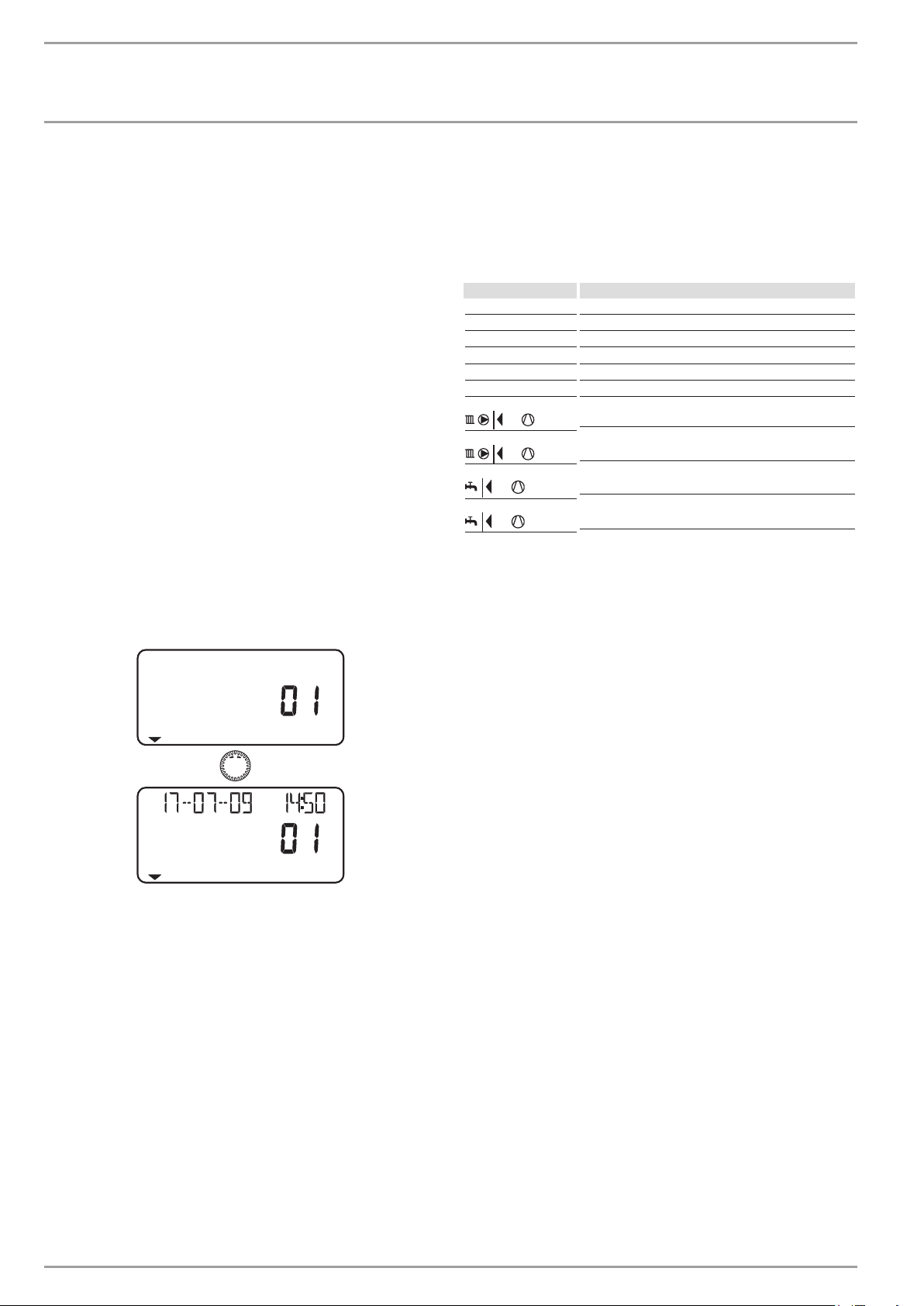
INSTALLATION
Commissioning
After that, the heat pump and the associated buffer primary pump
are switched ON. You terminate this function by pressing PRG or
by closing the control flap. OFF is displayed again.
36 RELAY TEST
Pressing PRG and continuing to turn the rotary selector allows you
to control the WPMiw relay outputs individually. The individual
outputs are displayed as plain text.
37 LCD TEST
Pressing PRG once initiates an LCD test. All display elements are
displayed in sequence.
38 FAULT LIST
The first fault code is displayed by pressing the PRG key. The fault
is described in plain text at the top of the display, the bottom
shows the fault number. Continuing to turn the rotary selector
still displays fault 1. As additional information, the display shows
the day, month and year together with the relevant time, when
the fault occurred.
In total, 20 faults can be displayed. You can reset the fault list via
a hardware reset.
Example:
The high pressure switch has responded on the 07/17/09 at 14:50
h representing the latest fault in the heat pump.
pressing PRG. The compressor starts again. The fault remains
stored in the fault list.
43 RUNTIMES
Under the RUNTIMES parameter, you can scan the heat pump
values. These values can only be reset via a hardware reset.
WPMIW INFO Meaning
RNT COMP HTG Runtime - compressor heating mode
RNT COMP DHW Runtime - compressor in DHW mode
RUNTIME DHC 1 DHC runtime stage 1
RUNTIME DHC 2 DHC runtime stage 2
RUNTIME DHC 1 2 DHC runtime stage 1 and 2
RNT COMP COO Runtime - compressor in cooling mode
EL OUTPUT DAY Electrical output of compressor in heating mode since
0:00 h today.
TTL EL OUTPUT Total electrical output of compressor in heating mode.
EL OUTPUT DAY Electrical output of compressor in DHW mode since
0:00 h today.
TTL EL OUTPUT Total electrical output of compressor in DHW mode
HP SENSOR MAX
39 WPMIW SOFTWARE
Display of the current software version.
40 ANALYSIS
The bottom of the display shows the enabled stages. The two-digit
display shows the control unit’s internal calculation. A stage will
be switched every time the counter has counted down to zero. This
calculation depends on the controller dynamics and the control
deviation. For this, see controller dynamics.
41 DIAGNOSIS
Pressing PRG indicates whether a FEK is connected and which heat
pump type has been connected.
42 HEAT P RESET
The heat pump can be reset if a fault occurs. That fault is reset by
pressing PRG and setting the system to ON, followed by repeatedly
40 | WPF basic www.stiebel-eltron.com
Page 41

INSTALLATION
Commissioning
11.7 WPMiw commissioning report
No. Parameter Sett ing range Standard System value
1 Enter code 0000 to 9999 1000
2 Language German
3 Contrast -10 to +10 0
4 Display Actual return
5 Emergency mode ON / OFF OFF
6 Cooling mode ON / OFF OFF
7 Heat-up program ON / OFF OFF
8 Summer mode ON / OFF ON
9 Pump cycles ON / OFF OFF
10 Buffer primary pump – constant run ON / OFF ON
11 SET FIXED VALUE OFF / °C OFF
12 Source Ethylene glycol
13 MIN source temperature -10 °C to 10 °C -9 °C
14 Maximum return temperature 20 °C to 55 °C 50 °C
15 Maximum heating flow temperature 20 °C to 65 °C 60 °C
16 HP sensor 38 bar to 40 bar 38 bar
17 Maximum mixer temperature 20 °C to 90 °C 50 °C
18 Mixer dynamic 30 - 240 100
19 Frost protection -10 °C to 10 °C 4 °C
20 Select remote control Heating circuit 1
21 FE correction -5 K to +5 K 0
22 Room influence 0 to 20 5
23 Temperature limit, heating OFF to 30 °C OFF
24 Dual mode temperature, heat source 2 -20 °C to 30 °C -20 °C
25 Temperature limit, DHW OFF to 30 °C OFF
26 Dual mode temperature, DHW -20 °C to 30 °C -20 °C
27 DHW eco ON / OFF OFF
28 DHW hysteresis 1 °C to 10 °C 3 °C
29 DHW correction 1 K to 5 K 3 K
30 Pasteurisation ON / OFF OFF
31 Controller dynamics 1 – 30 20
32 Idle time af ter switching the compressor OFF 1 to 120 min 20 min
33 Remaining idle time
34 Single phase ON / OFF OFF
35 Quick start
36 Relay test
37 LCD test
38 Fault list
39 WPMiw software issue
40 Analysis
41 Diagnosis
42 Heat pump reset
43 Runtimes
www.stiebel-eltron.com WPF basic | 41
Page 42
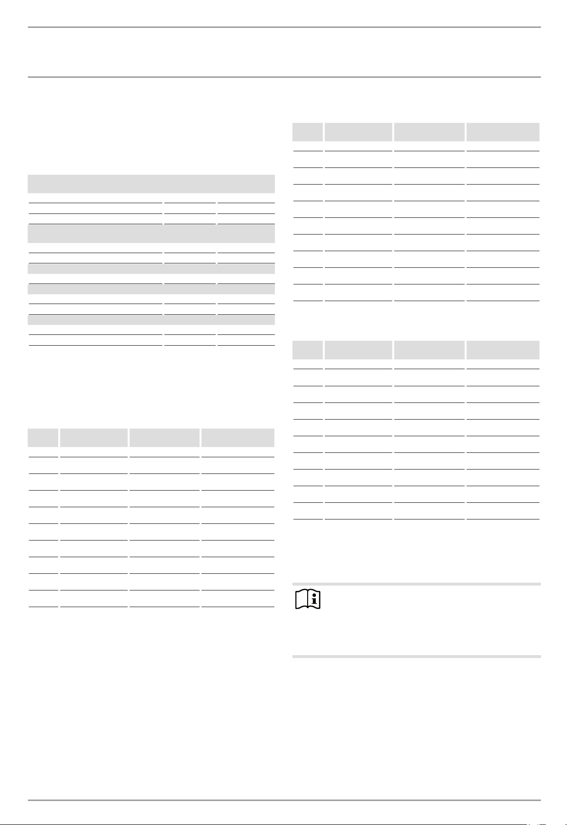
INSTALLATION
Settings
12. Settings
12.1 Standard settings
At the factory, the heat pump manager is programmed with the
following standard settings:
Switching times for heating circuit 1 and 2 (day mode)
Only the first switching time pair is preprogrammed.
Standard Setting range
Monday - Friday 6:00 - 22:00 00:00 – 23:59
Saturday - Sunday 07:00 – 23:00 00:00 – 23:59
Room temperature 1 and 2
Standard sett ings are without night setback.
Room temperature in day mode 20 °C 5 – 30 °C
Room temperature in night mode 20 °C 5 – 30 °C
DHW program switching times
Monday - Sunday 0:00 – 24:00 00:00 – 23:59
DHW temperature
DHW day temperature 47 °C 10 – 60 °C
DHW night temperature 10 °C 10 – 60 °C
Heating curve slope
Heating curve 1 0,6 0 - 3
Heating curve 2 0,2 0 - 3
12.2 Heating and DHW programs
You may enter your individual programs into the following tables.
12.2.1 Heating program, heating circuit 1
12.2.2 Heating program, heating circuit 2
Switching time
pair I
Mo
Tu
We
Th
Fr
Sa
Su
Mo - Fr
Sa - Su
Mo - Su
Switching time
pair II
Switching time
pair III
12.2.3 DHW program
Switching time
pair I
Mo
Tu
We
Th
Switching time
pair II
Switching time
pair III
Switching time
pair I
Mo
Tu
We
Th
Fr
Sa
Su
Mo - Fr
Sa - Su
Mo - Su
Switching time
pair II
Switching time
pair III
Fr
Sa
Su
Mo - Fr
Sa - Su
Mo - Su
12.3 Appliance handover
Explain the function of the appliance to users and familiarise them
with its operation.
Note
Hand over these operating and installation instructions
to the user for safe-keeping. All information in these
instructions must be closely observed. The instructions
provide information on safety, operation, installation and
maintenance of the appliance.
42 | WPF basic www.stiebel-eltron.com
Page 43
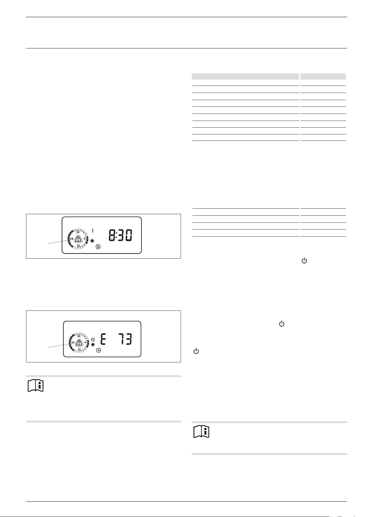
INSTALLATION
Troubleshooting
13. Troubleshooting
13.1 Fault display
Faults/errors in the system or in the heat pump are indicated on
the display. All parameters required for an in-depth system analysis can be checked under the system menu items COMMISSIONING
and TEMPERATURES. For troubleshooting, analyse all available
parameters before opening the heat pump control panel.
The controller will not indicate that the booster heater high limit
safety cut-out has responded. The high limit safety cut-out can be
reset by your contractor through pressing the reset button. The
high limit safety cut-out response is generally caused by air in the
heating circuit or an inadequate heating flow rate.
Check the heating flow rate and ventilate the heating system.
13.1.1 Heat pump-specific or hardware faults
All faults are displayed.
Example: High pressure fault
HP SENSOR MAX
Observe the list under system parameter TEMPERATURES.
Sensor Fault code
Outside temperature E 75
Remote control E 80
Actual DHW temperature E 76
Actual heat pump return temperature (H1) E 73
Actual mixer flow temperature (H2) E 70
Actual heat pump flow temperature E 72
Actual source flow temperature E 71
High pressure sensor E 130
LP sensor E 128
13.1.3 Fault message with DCO enabled
In connection with the dial-up connection controller DCO enabled,
the sensor faults listed above result in the transmission of the error
codes (E75 to E130) by SMS to the authorised recipient.
In addition, the following fault codes are transmitted as text message:
Contactor stuck E 20
No power E 21
Low pressure E 22
HIGH PRESSURE E 23
HP sensor max E 24
1
1 Fault message (flashing)
All faults cause the heat pump to shut down. The idle period will
be set and, with the exception of MAX HOT GAS T, ALl faults are
written to the fault list.
13.1.2 Sensor break = sensor fault
SENSOR BROKEN
1
1 Fault message (flashing)
Note
This fault code refers to temperature sensors that can be
called up under the parameter TEMPERATURES. These
faults are not entered into the fault list. The system will
not be shut down. The display message will extinguish
immediately after the fault has been removed.
13.1.4 Checking brine pressure
26�03� 01�1063
Check brine pressure if the heat pump is blocked for more
than three hours (standby symbol flashes [
Check the brine pipe for leaks.
Remedy any leaks.
Recharge the system (see chapter “Installation/ Installation/
Installing the heat source system/ Connection and brine
charging/ Charging the brine circuit”).
13.1.5 The heat pump does not run
The heat pump is in standby mode [
Remedy: Change to automatic mode
The power supply has been blocked; the standby symbol flashes
]
[
26�03�01�1064
Remedy: Wait; the heat pump restarts automatically at the end
of the blocking time.
There is no heat demand
Remedy: System parameter TEMPERATURES, check temperatures
and compare the actual and set temperatures.
Possibly incorrect fuse rating
Remedy: See Specification
]
]).
Note
Under these circumstances, you can only restart the heat
pump after the fault has been removed and the heat
pump has been reset (parameter WPM RESET).
Additional parameters available for system analysis:
Quick start:
Check the heat pump compressor by implementing a quick start
www.stiebel-eltron.com WPF basic | 43
Page 44
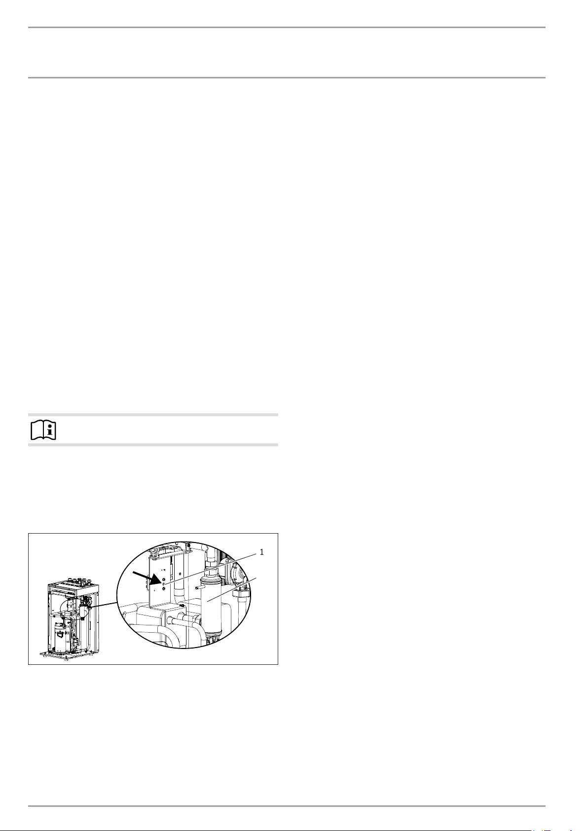
INSTALLATION
Troubleshooting
Relay test:
Test all relays in the WPMiw
Analysis:
System analysis for checking all existing BUS subscribers
Reset HP:
Heat pump reset to clear all saved faults.
WPMiw reset options
Reset by turning the rotary selector from Auto to Reset and back
again. All system-specific programs remain intact. The fault list
will not be deleted.
Reset by turning the rotary selector from Auto to Reset and back
again while holding down the PRG key. The display must show
EEPR (EEPROM hardware reset). The WPMiw is reset into the delivered condition. The fault list will be deleted.
After a hardware reset, if the control flap is closed, NO HEAT P
PARA is displayed.
The heat pump type must be re-entered.
When the control flap is opened, HEAT PUMP is displayed. After
pressing the PRG button, the heat pump type can then be selected
using the rotary selector. The heat pump type must be confirmed
by pressing the PRG button.
Note
The heat pump type can be found on the type plate.
The parameter SINGLE PHASE must be returned to ON on single
phase appliances.
13.2 Resetting the high limit safety cut-out
If the heating water temperature exceeds 85°C, the electric emergency/booster heater shuts down.
1
2
1 Electric emergency/booster heater
2 High limit safety cut-out reset button
Remove the cause of the fault.
Reset the high limit safety cut-out by pressing the reset but-
ton. To do so, use a pointed object.
Check whether the heating water is being circulated at a suf-
ficient flow rate.
26�03�01�1893
44 | WPF basic www.stiebel-eltron.com
Page 45

INSTALLATION
Maintenance
13.3 Fault list parameter
Check and remove all faults in the fault list.
Fault display Reason for fault code triggered by control unit: Possible cause of fault/remedy
HP sensor max
Controlled shutdown;
no fault
LOW PRESSURE The system will be permanently shut down after the fault has occurred five times
CONTACT STUCK Each time the compressor is switched off, the system checks af ter ten seconds,
HIGH PRESSURE After the compressor has started, and after a delay of 15 seconds, masking checks,
NO OUTPUT
POWER-OFF
MIN SRCE TEMP The defined minimum source temperature was not reached.
MAX HOT GAS T
Controlled shutdown;
no fault
The fault will be written to the fault list and the system will be permanently shut
down after the system has been shut down five times within the operating time (5
minutes). Generally, the shutdown via the HP sensor max. is a controlled shutdown
that is only displayed for information and for the duration of the idle time, i.e. it is
not entered into the fault list. Only frequent shutdowns over a short period of time
point towards a fault and are therefore entered into the fault list.
within the operating time (idle time x 50 plus 20 minutes). The fault will be written
to the fault list after it has occurred for the first time.
whether the relay K9 is open. A contactor is stuck, if that is the case. The fault is
written to the fault list, and the system is permanently shut down.
whether the relay K9 is open. A HP limit switch has responded, if that is the case.
The fault is written to the fault list, and the system is permanently shut down.
After the compressor has started, the pressure must have risen by 2 bar within 10
seconds. A fault has occurred, if that is not the case, and the fault will be written
into the fault list, if that is its first occurrence, and the system is permanently shut
down.
The power supply utility has blocked the heat pump (see chapter “Installation/
Troubleshooting/ Fault indicators on the display/ The heat pump is not running”).
The fault is written to the fault list. The compressor starts again after the selected
idle time has expired.
The compressor will be stopped for the minimum idle time if a hot gas temperature
of 130 °C is exceeded. This is a normal controlled shutdown that is not entered into
the fault list. The reason for the shutdown is displayed for information during the
idle time.
Only when a fault has been entered into the fault list:
Monitor the flow temperature and check the HP sensor.
Check the flow rate and the temperature on the heating
side.
Check the flow rate and the layout of the source side.
Check the refrigerant level.
Check contactors K1 and K2 and replace if required.
Monitor the flow temperature and check the HP sensor.
Check the flow rate and the temperature on the heating
side.
Compressor turns in the wrong rotational direction.
Change the rotational direction by interchanging two
supply cores.
No action required. If this message is still shown despite
enabling by the power supply utility, the brine pressure
switch has responded.
Check the brine line for leaks and remedy any that are
found. Subsequently recharge the system (see chapter
"Installation/ Installation/ Installing the heat source
system/ Connection and brine charging/ Charging the
brine circuit").
Check the minimum, source temperature and change it
if required.
Check the source flow rate: Check source design.
This requires no action, as it is a controlled shutdown.
14. Maintenance
We recommend a regular inspection (to establish the current condition of the system), and maintenance if required (to return the
system to its original condition).
If heat meters are installed, their sieves should be cleaned regularly.
www.stiebel-eltron.com WPF basic | 45
Page 46
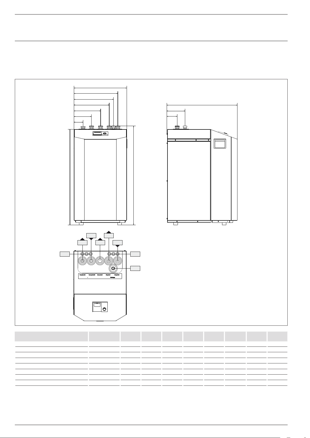
INSTALLATION
510
Specication
15. Specification
15.1 Connections
85
170
255
382
340
425
680
176
100
926
f02
f01
d29
960
e01
e02
b03b02
c11
D0000016823
WPF 5
basic
b02 Entry electrical cables I
b03 Entry electrical cables II
c11 Safety assembly
d29 Heat exchanger flow Male thread G 1 1/4 G 1 1/4 G 1 1/4 G 1 1/4 G 1 1/4 G 1 1/4 G 1 1/4 G 1 1/4
e01 Heating flow Male thread G 1 1/4 G 1 1/4 G 1 1/4 G 1 1/4 G 1 1/4 G 1 1/4 G 1 1/4 G 1 1/4
e02 Heating return Male thread G 1 1/4 G 1 1/4 G 1 1/4 G 1 1/4 G 1 1/4 G 1 1/4 G 1 1/4 G 1 1/4
f01 Heat source flow Male thread G 1 1/4 G 1 1/4 G 1 1/4 G 1 1/4 G 1 1/4 G 1 1/4 G 1 1/4 G 1 1/4
f02 Heat source return Male thread G 1 1/4 G 1 1/4 G 1 1/4 G 1 1/4 G 1 1/4 G 1 1/4 G 1 1/4 G 1 1/4
WPF 7
basic
WPF 10
basic
WPF 13
basic
WPF 16
basic
WPF5S
basic
WPF 7 S
basic
WPF 10 S
basic
46 | WPF basic www.stiebel-eltron.com
Page 47
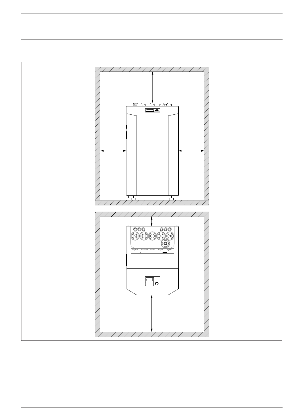
INSTALLATION
Specication
15.2 Installation dimensions
≥500
≥500
≥500
≥50
≥1000
www.stiebel-eltron.com WPF basic | 47
D0000019257
Page 48
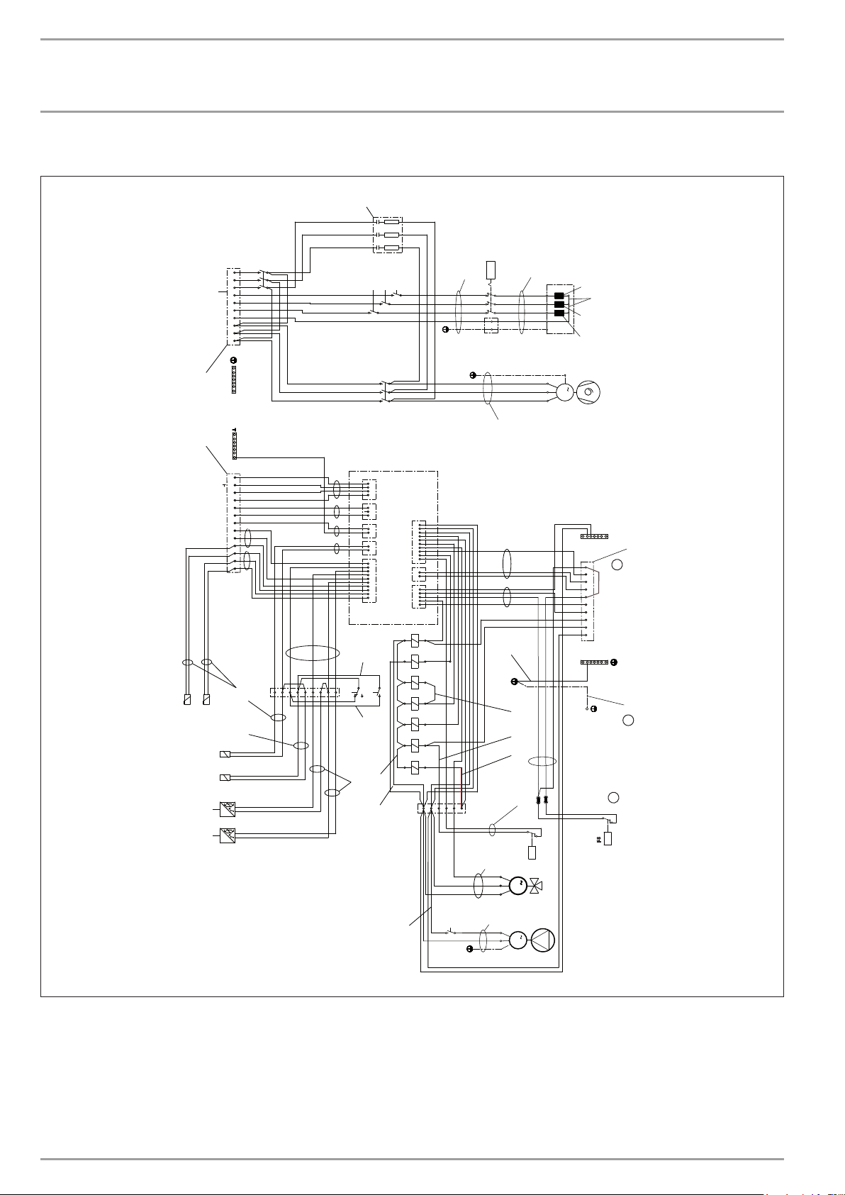
INSTALLATION
erdrahtungsplan WP
Specication
15.3 Wiring diagram WPF 5 basic
X3
L3
10
3 5
L2
98
1
L1
Solepumpe
7
L3
6
L2
5
L1
4
N
3
L3
2
L2
WP (Netz) DHC
1
L1
080
br
br
sw
sw
sw
ws
ws
K4
6
4
2
Z3
K5
K7
K6
1
3
1
3
3
1
F5
T >
500
31
21
11
X23
X31
510
E1
32
22
12
P3=3200W
P2=3000W
P1=2600W
620
400
420
T
T
B2
F 5 basic
X23
X26
"+"
13
12
L
11
H
10
Fernb.3
9
Fernb.1
8
T(MK)
7
T(A)
6
T(WW)
5
Kleinspannung
B2
4
B2
3
B1
2
B1
1
X2
1/810
B1
1/820
T
B3
T
B5
22
l
1
p
P3
l
1
p
P1
1234578
X28
6
4
3 5
2
1
K2
R
T3
S
T2
M
3
C
T1
M1
1/185
4
3
X15
2
X23
1
3
2
1
2
1
2
1
10
9
8
7
65
4
3
2
1
15-17 V
680
11
9
6
14
K9
K2
12
13
14
680
530
X14
X13
X12
X11
700
430
B
X22
X21
X20
A2
4
B
B
B
A2
X1
710
A1
1
2
3
4
56
7
8
9
10
2
1
5
4
3
2
1
A1
K4
1
X73
K9
A
K7K6
A
A
K5
A1
K2
A
K8
6
1
234
5
sw
bl
br
K8
3
1
X27
1/465
L`
L``
N
520
L
N
670
M3
M2
X27
650
630
690
1/420
F2
1
M
M
1
> p
X25
N
410
F8
i
10
HKP
9
Mz
87
Ma
EVU
6
MKP
5
Kühlen
4
KS
3
Steuerung
ON
21
L
X4
X24
720
g
X39
i
> p
F8
V
48 | WPF basic www.stiebel-eltron.com
D0000048149
Page 49

INSTALLATION
Specication
A1 Heat pump manager WPMi
B1 Temperature sensor heat pump flow
B2 Temperature sensor heat pump return
B3 Temperature sensor heat source
B5 Hot gas temperature sensor
E1 elektr. booster heater (DHC)
F1 Low pressure switch (only in WPW)
F2 High pressure switch
F5 High limit safety cut-out for DHC
F8 Brine pressure switch
K2 Compressor start contactor
K4 Contactor – brine pump
K5 Electric booster heater relay
K6 Electric booster heater relay
K7 Electric booster heater relay
K8 Pump motor relay
K9 Contactor relay stuck
M1 Compressor motor
M2 Pump motor
M3 Motorised diverter valve
P1 High pressure transducer
P3 Low pressure transducer
X1 Terminals
X2 LV terminal
X3 Power supply
X4 Control terminals
X11 Socket plug 10-PIN WPMi
X12 Plug WQ temperature WPMiw
X13 Plug mixer circuit temp. WPMiw
X14 Plug remote control WPMiw
X15 BUS plug WPMiw
X20 Plug pumps and power-OFF WPMiw
X21 Plug mixer control WPMiw
X22 Socket plug 10-PIN control WPMi
X23 Power supply earth block
X24 Earth block control
X25 N block control
X26 Earth block LV
X27 Earth plug-in block
X28 Socket terminal strip
X31 Electric booster heater terminal
X39 Earthing the front sheet metal cover
X73 Connectors in cable channel
Z3 Suppressor
www.stiebel-eltron.com WPF basic | 49
Page 50
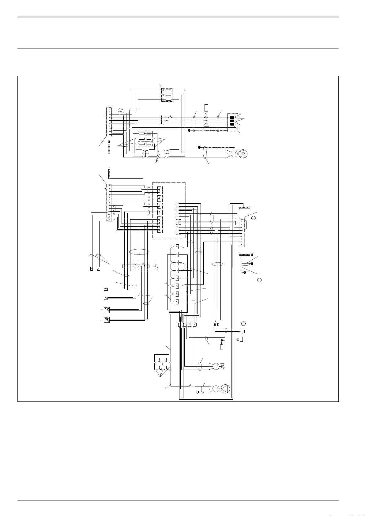
INSTALLATION
erdrahtungsplan WP
Specication
15.4 Wiring diagram WPF 7 basic | WPF 10 basic | WPF 13 basic | WPF 16 basic
080
br
br
sw
ws
ws sw
Z3
K5
K6
K7
3
1
3
1
3
1
R1
R2R3
600
6
53
1
6
4
4
2
K1
1 3 5
2
K2
610
4
3
X15
2
1
A1
3
X14
2
1
1
X22
2
2
X13
3
4
5
6
2
7
X12
1 1
8
9
10
10
9
X11
8
2
X21
7
1
6
5
4
5
3
X20
4
2
3
1
2
430
700
1
A1
A2
K4
1
4
K9
A
B
A
B
K6 K7
A
B
K5
A1
A2
K2
A1
A2
K1
A
B
K8
2
1
X1
bl
br
15-17 V
12
8
9
K9
11
530
345
F5
T >
500
31
21
11
X23
X23
510
E1
32
22
12
X31
R
T3
S
T2
M
3
C
T1
M1
1/185
X4
X24
650
630
690
6
sw
T
T
B2
X3
L3
10
L2
9
L1
8
Solepumpe
7
L3
6
L2
5
L1
4
N
32
L3
L2
WP (Netz) DHC
1
L1
400
X23
X26
420
"+"
13
12
L
11
H
10
Fernb.3
9
Fernb.1
8
T(MK)
7
T(A)
6
T(WW)
5
Kleinspannung
B2
4
B2
3
B1
2
B1
1
X2
B1
T
B3
T
B5
2
l
1
p
P3
2
l
1
p
P1
531
600
1/810
1/820
K4
6
4
2
1
X28
23567
4
P3=3200W
P2=3000W
P1=2600W
10
9
87
6
5
4
3
21
X39
j
620
X25
F8
HKP
Mz
Ma
EVU
MKP
Kühlen
KS
ON
L
N
j
Steuerung
X27
410
670
720
h
> p
F8
600
K1
K2
13
13
14
14
K1
K2
-1
-2
-1
F 7, 10, 13, 16 basic
V
50 | WPF basic www.stiebel-eltron.com
-2
610
600
K8
3
1
X27
1/465
L`
L``
N
520
L
N
1/420
M
M3
M
M2
> p
F2
1
1
D0000048087
Page 51

INSTALLATION
Specication
A1 Heat pump manager WPMi
B1 Temperature sensor heat pump flow
B2 Temperature sensor heat pump return
B3 Temperature sensor heat source
B5 Hot gas temperature sensor
E1 elektr. booster heater (DHC)
F1 Low pressure switch (only in WPW)
F2 High pressure switch
F5 High limit safety cut-out for DHC
F8 Brine pressure switch
K1 Contactor resistances
K2 Compressor start contactor
K4 Contactor – brine pump
K5 Electric booster heater relay
K6 Electric booster heater relay
K7 Electric booster heater relay
K8 Pump motor relay
K9 Contactor relay stuck
M1 Compressor motor
M2 Pump motor
M3 Motorised diverter valve
P1 High pressure transducer
P3 Low pressure transducer
R1 Start-up resistance
R2 Start-up resistance
R3 Start-up resistance
X1 Terminals
X2 LV terminal
X3 Power supply
X4 Control terminals
X11 Socket plug 10-PIN WPMi
X12 Plug WQ temperature WPMiw
X13 Plug mixer circuit temp. WPMiw
X14 Plug remote control WPMiw
X15 BUS plug WPMiw
X20 Plug pumps and power-OFF WPMiw
X21 Plug mixer control WPMiw
X22 Socket plug 10-PIN control WPMi
X23 Power supply earth block
X24 Earth block control
X25 N block control
X26 Earth block LV
X27 Earth plug-in block
X28 Socket terminal strip
X31 Electric booster heater terminal
X39 Earthing the front sheet metal cover
Z3 Suppressor
www.stiebel-eltron.com WPF basic | 51
Page 52
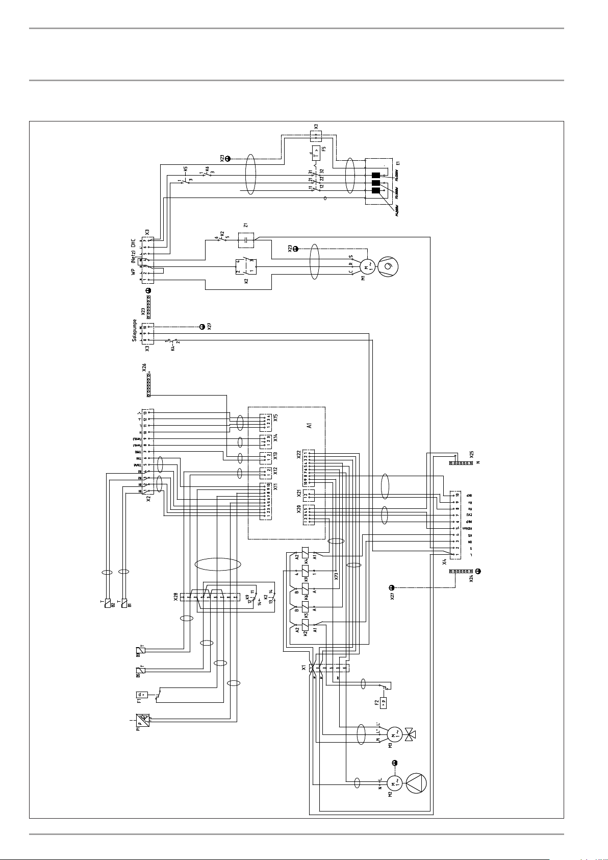
INSTALLATION
Specication
15.5 Wiring diagram WPF 5-10 S basic
52 | WPF basic www.stiebel-eltron.com
D0000048150
Page 53

INSTALLATION
Specication
A1 WPMiw heat pump manager
B1 Temperature sensor heat pump flow
B2 Temperature sensor heat pump return
B3 Temperature sensor heat source
B5 Hot gas temperature sensor
E1 Emergency heater (DHC)
F1 Low pressure switch
F2 High pressure switch
F5 High limit safety cut-out for DHC
K2 Compressor start contactor
K4 Contactor – brine pump
K5 Emergency heater relay
K6 Emergency heater relay
K9 Contactor relay stuck
M1 Compressor motor
M2 Pump motor
M3 Motorised diverter valve
P1 High pressure transducer
X1 Terminals
X2 LV terminal
X3 Power supply
X4 Control terminals
X11 Plug temperature sensor WPMiw
X12 Plug WQ temperature WPMiw
X13 Plug mixer circuit temp. WPMiw
X14 Plug remote control WPMiw
X15 BUS plug WPMi
X20 Plug pumps and power-OFF WPMiw
X21 Plug mixer control WPMiw
X22 Plug external pump WPMiw
X23 Power supply earth block
X24 Earth block control
X25 N block control
X26 Earth block LV
X27 Earth plug-in block
X28 2-pin socket terminal strip
X31 Emergency heater terminal
X32 Front cover terminal.
X73 Connectors in cable channel
Z1 Compressor capacitor, run
www.stiebel-eltron.com WPF basic | 53
Page 54
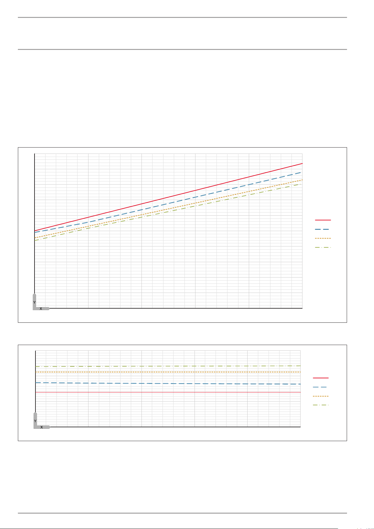
INSTALLATION
1
2
3
4
1
2
3
4
Specication
15.6 Output diagrams WPF 5 basic
Legend for output diagrams
Y Heating output [kW] / power consumption [kW] / coefficient of performance e [-]
X Inlet temperature of the WQA medium [°C]
1 Flow temperature 35 °C
2 Flow temperature 45 °C
3 Flow temperature 55 °C
4 Flow temperature 60 °C
Heating output WPF 5 basic
10
9
8
7
6
5
4
3
2
1
0
-5 0 5 10 15 20
Power consumption WPF 5 basic
3
2
D0000022775
1
0
-5 0 5 10 15 20
54 | WPF basic www.stiebel-eltron.com
D0000022775
Page 55
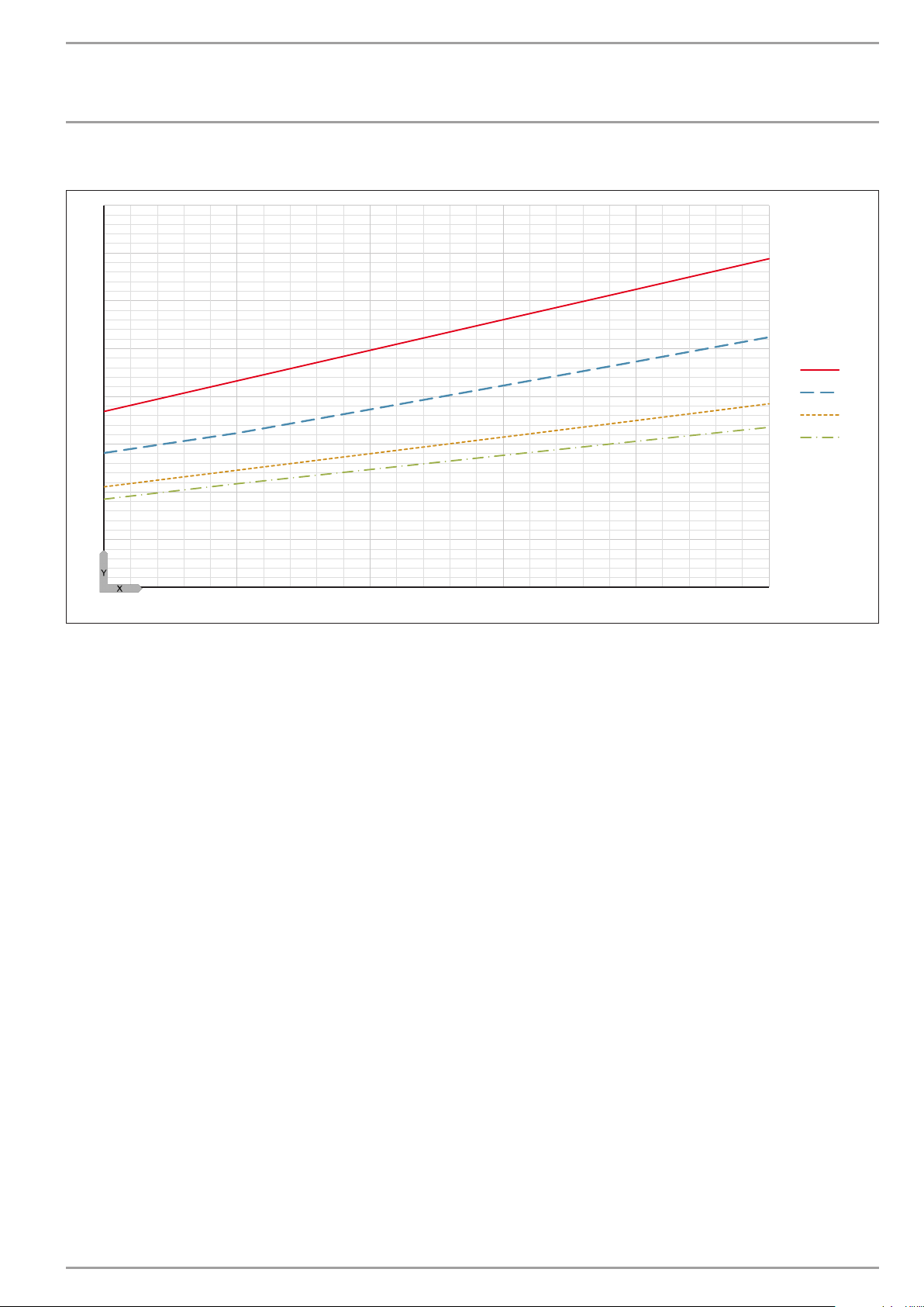
INSTALLATION
1
2
3
4
Specication
Coefficient of performance WPF 5 basic
8
7
6
5
4
3
2
1
0
-5 0 5 10 15 20
D0000022775
www.stiebel-eltron.com WPF basic | 55
Page 56
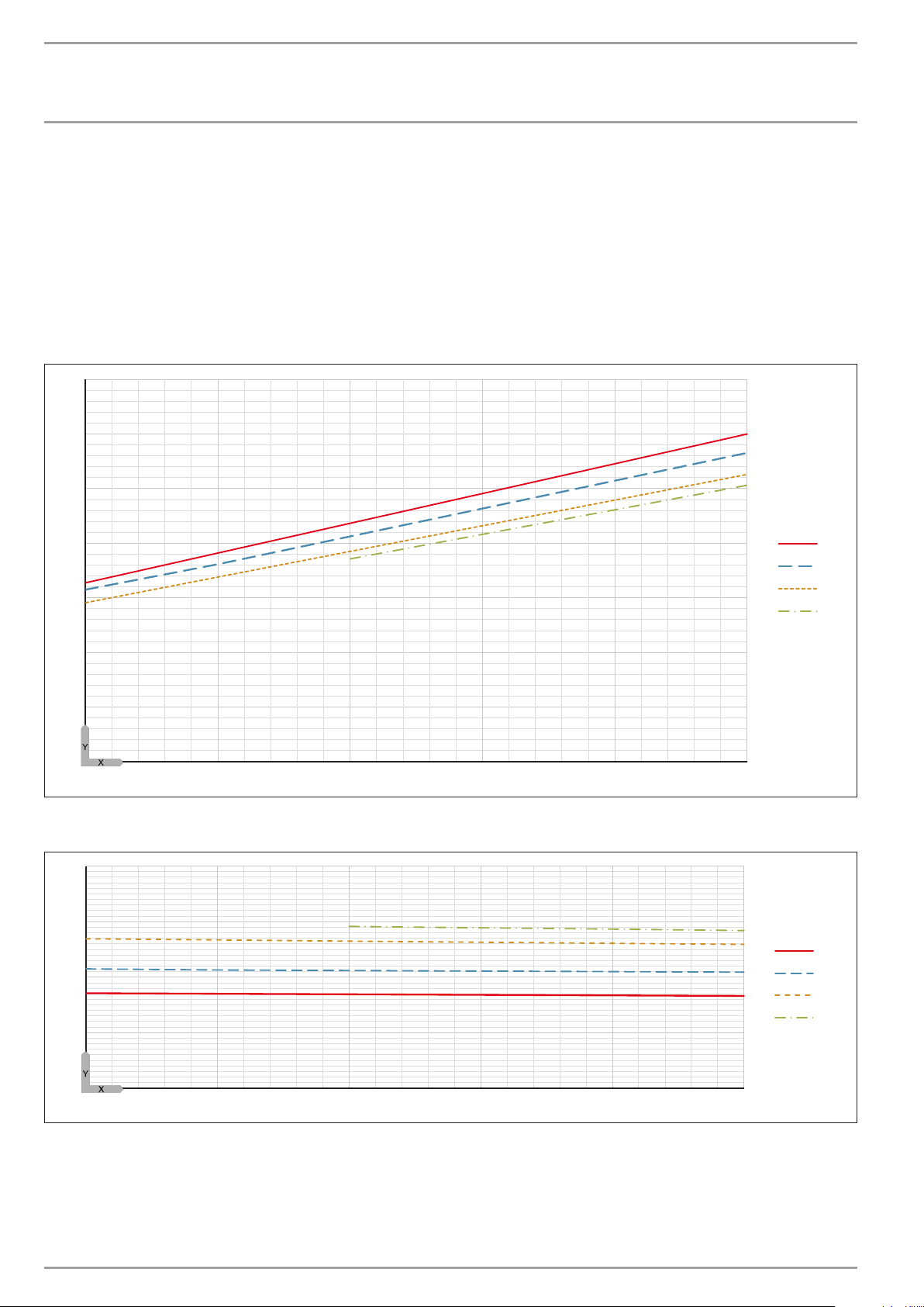
INSTALLATION
1
2
3
4
1
2
3
4
Specication
15.7 Output diagrams WPF 7 basic
Legend for output diagrams
Y Heating output [kW] / power consumption [kW] / coefficient of performance e [-]
X Inlet temperature of the WQA medium [°C]
1 Flow temperature 35 °C
2 Flow temperature 45 °C
3 Flow temperature 55 °C
4 Flow temperature 60 °C
Heating output WPF 7 basic
14
12
10
8
6
4
2
0
-5 0 5 10 15 20
Power consumption WPF 7 basic
4
3
2
D0000022775
1
0
-5 0 5 10 15 20
56 | WPF basic www.stiebel-eltron.com
D0000022775
Page 57
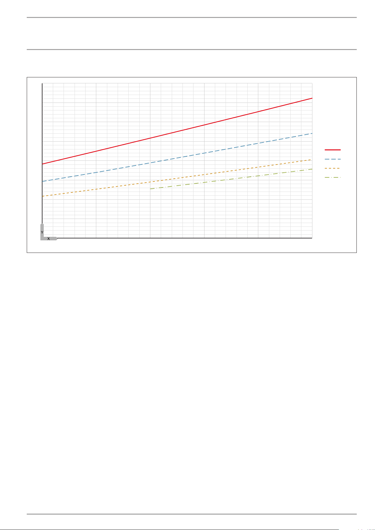
INSTALLATION
1
2
3
4
Specication
Coefficient of performance WPF 7 basic
8
7
6
5
4
3
2
1
0
-5 0 5 10 15 20
D0000022775
www.stiebel-eltron.com WPF basic | 57
Page 58
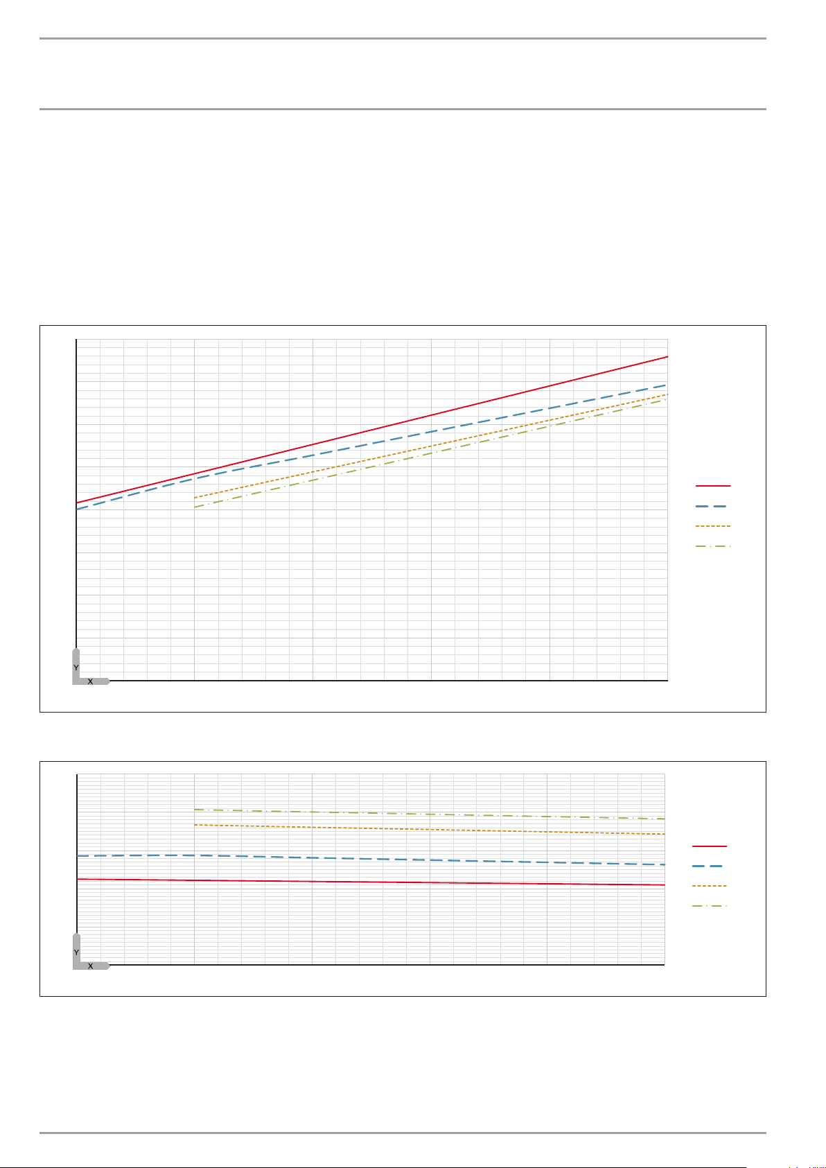
INSTALLATION
1
2
3
4
1
2
3
4
Specication
15.8 Output diagrams WPF 10 basic
Legend for output diagrams
Y Heating output [kW] / power consumption [kW] / coefficient of performance e [-]
X Inlet temperature of the WQA medium [°C]
1 Flow temperature 35 °C
2 Flow temperature 45 °C
3 Flow temperature 55 °C
4 Flow temperature 60 °C
Heating output WPF 10 basic
16
14
12
10
8
6
4
2
0
-5 0 5 10 15 20
Power consumption WPF 10 basic
5
4
3
D0000022775
2
1
0
-5 0 5 10 15 20
58 | WPF basic www.stiebel-eltron.com
D0000022775
Page 59
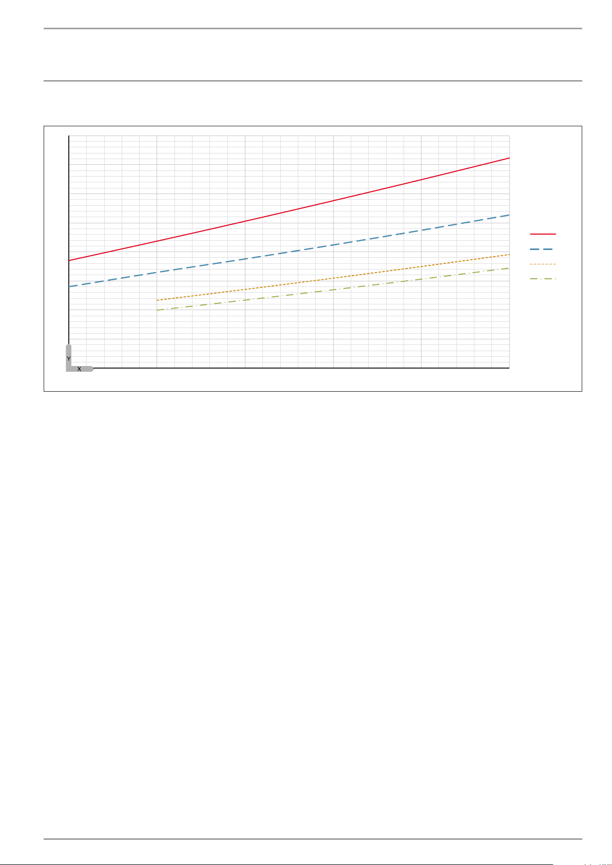
INSTALLATION
1
2
3
4
Specication
Coefficient of performance WPF 10 basic
8
7
6
5
4
3
2
1
0
-5 0 5 10 15 20
D0000022775
www.stiebel-eltron.com WPF basic | 59
Page 60
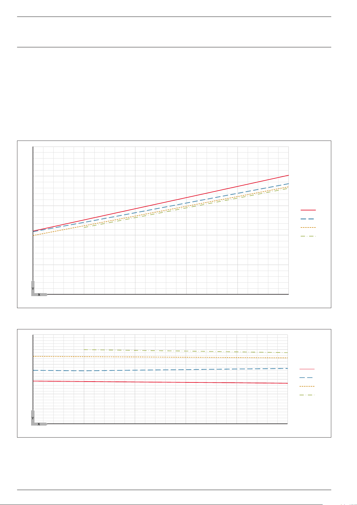
INSTALLATION
1
2
3
4
1
2
3
4
Specication
15.9 Output diagrams WPF 13 basic
Legend for output diagrams
Y Heating output [kW] / power consumption [kW] / coefficient of performance e [-]
X Inlet temperature of the WQA medium [°C]
1 Flow temperature 35 °C
2 Flow temperature 45 °C
3 Flow temperature 55 °C
4 Flow temperature 60 °C
Heating output WPF 13 basic
25
20
15
10
5
0
-5 0 5 10 15 20
Power consumption WPF 13 basic
6
5
4
3
D0000022775
2
1
0
-5 0 5 10 15 20
60 | WPF basic www.stiebel-eltron.com
D0000022775
Page 61
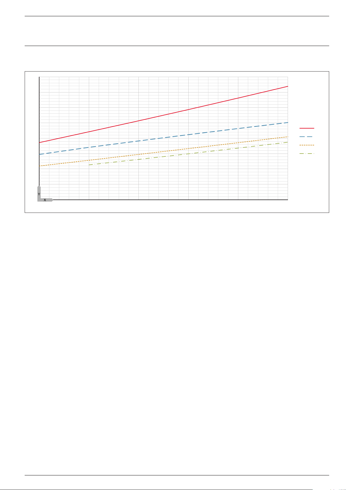
INSTALLATION
1
2
3
4
Specication
Coefficient of performance WPF 13 basic
8
7
6
5
4
3
2
1
0
-5 0 5 10 15 20
D0000022775
www.stiebel-eltron.com WPF basic | 61
Page 62
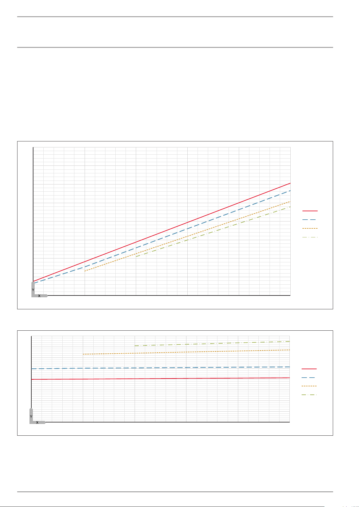
INSTALLATION
1
2
3
4
1
2
3
4
Specication
15.10 Output diagrams WPF 16 basic
Legend for output diagrams
Y Heating output [kW] / power consumption [kW] / coefficient of performance e [-]
X Inlet temperature of the WQA medium [°C]
1 Flow temperature 35 °C
2 Flow temperature 45 °C
3 Flow temperature 55 °C
4 Flow temperature 60 °C
Heating output WPF 16 basic
29
27
25
23
21
19
17
15
13
-5 0 5 10 15 20
Power consumption WPF 16 basic
8
7
6
5
D0000022775
4
3
2
1
0
-5 0 5 10 15 20
62 | WPF basic www.stiebel-eltron.com
D0000022775
Page 63
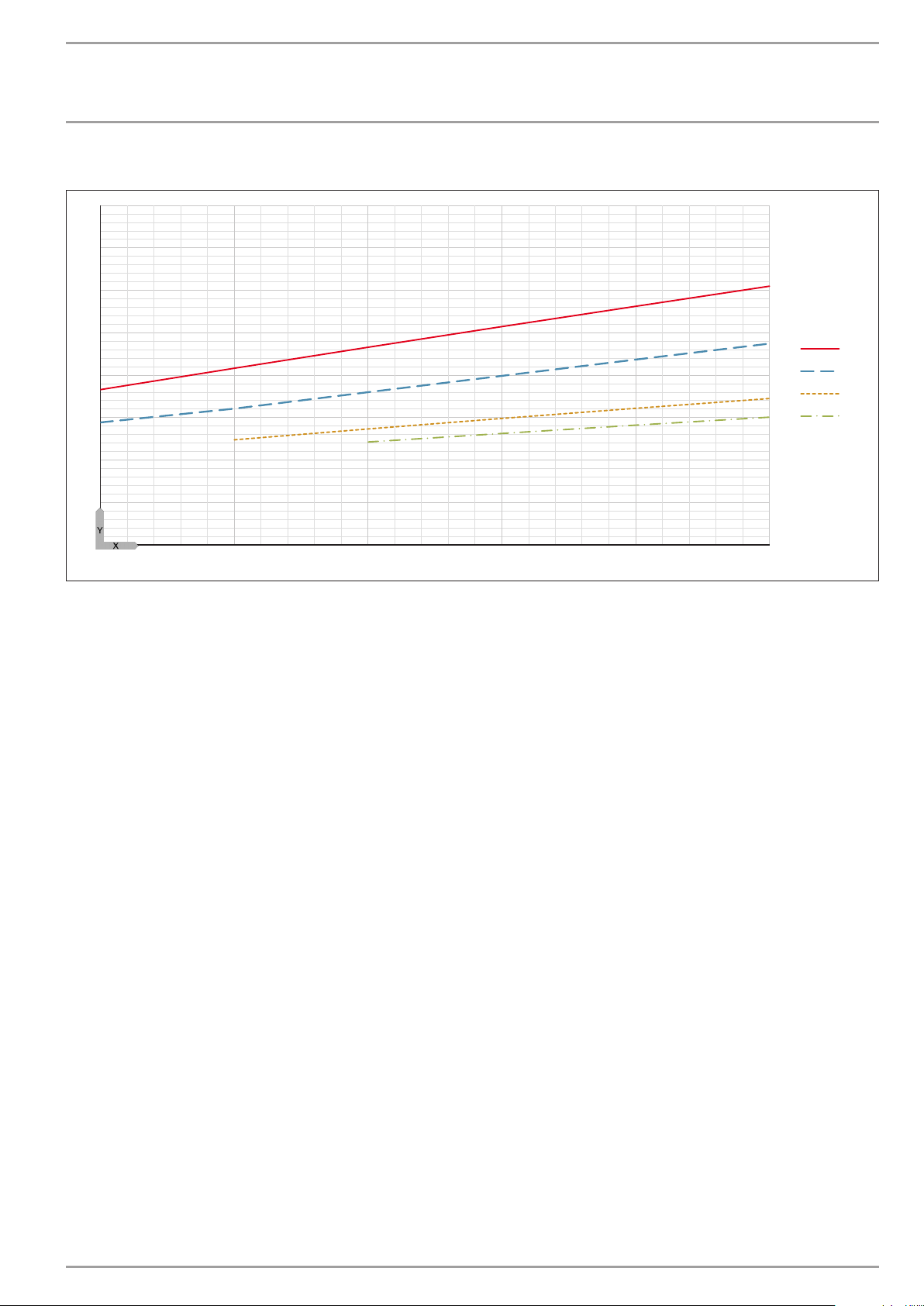
INSTALLATION
1
2
3
4
Specication
Coefficient of performance WPF 16 basic
8
7
6
5
4
3
2
1
0
-5 0 5 10 15 20
D0000022775
www.stiebel-eltron.com WPF basic | 63
Page 64
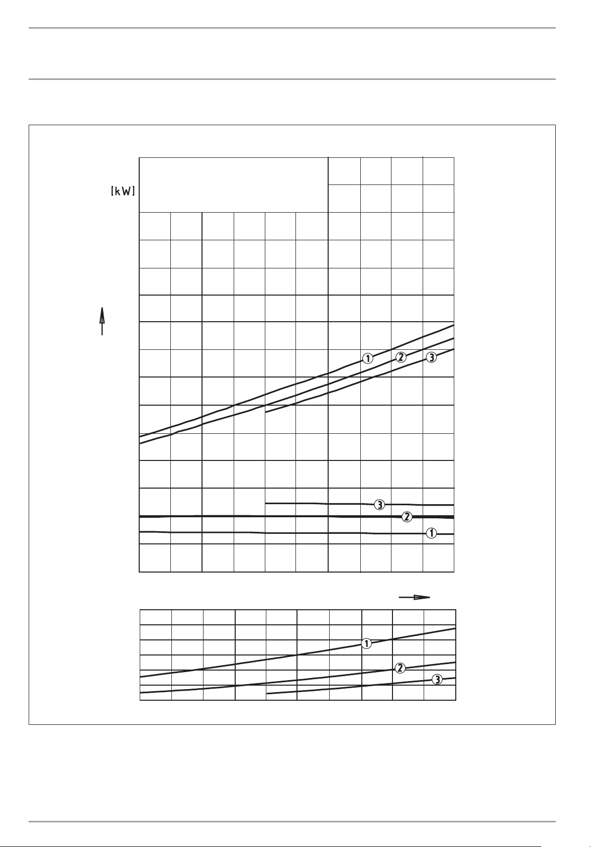
INSTALLATION
Specication
15.11 Output diagrams WPF 5 S basic
Ethylenglykol/W assergemisch mit 33 V ol.% Ethylenglykol
15
1=V orlauf temperatur 35 °C V olllast
2=V orlauf temperatur 50 °C V olllast
3=V orlauf temperatur 60 °C V olllast
10
HP
.
Q
5
Heat Output
HP
Power consumption P
0
-5 0 5
8
HP
7
6
5
4
3
2
Performance factor ε
1 Flow temperature 35 °C
2 Flow temperature 50 °C
3 Flow temperature 60 °C
10 15 20
Inlet temperature of Source Medium [°C]
°C
26�03�01�0257
64 | WPF basic www.stiebel-eltron.com
Page 65
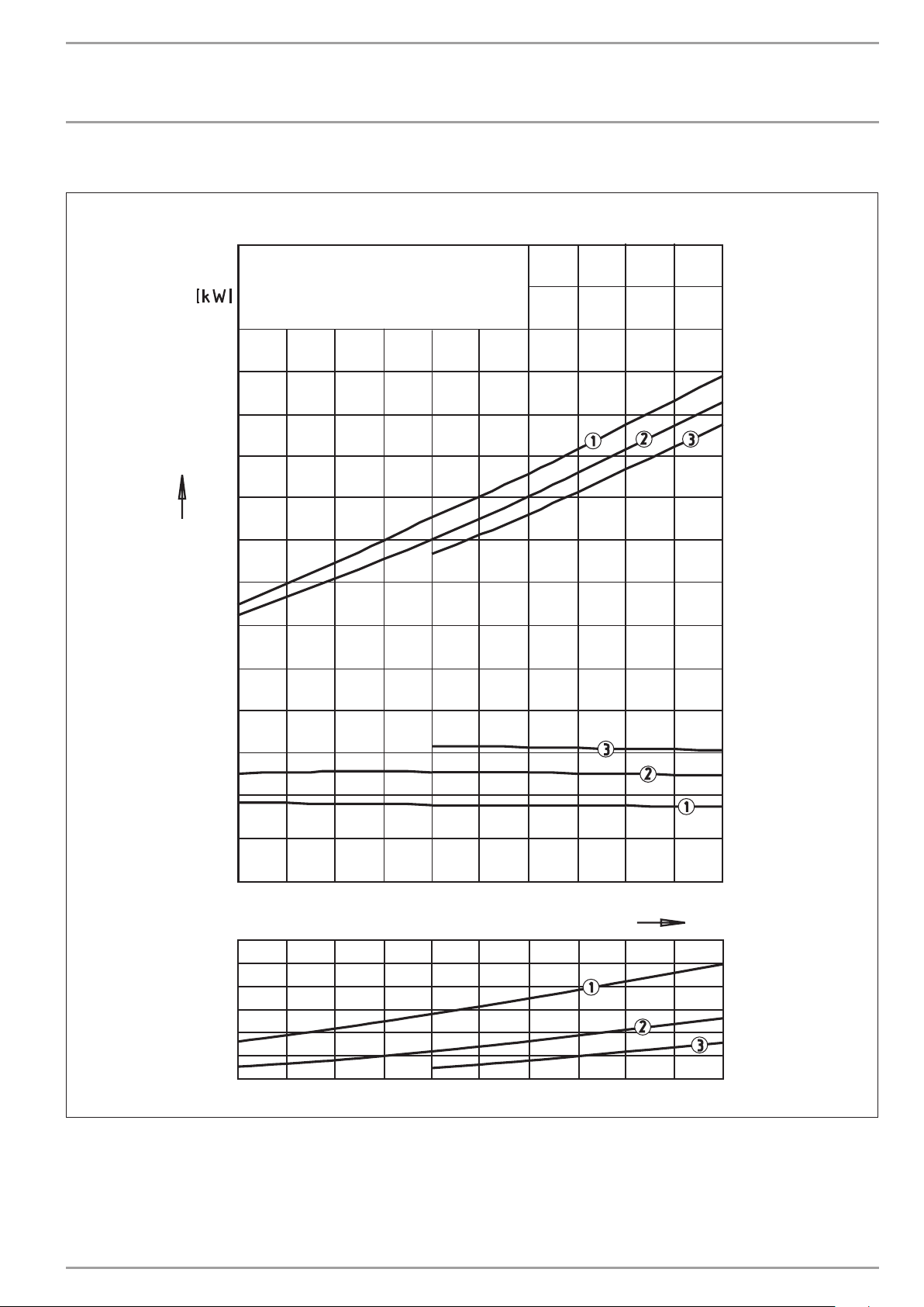
INSTALLATION
Specication
15.12 Output diagrams WPF 7 S basic
Ethylenglykol/Wassergemisch mit 33 Vol.% Ethylenglykol
15
1 = Vorlauftemperatur 35 °C Volllast
2 = Vorlauftemperatur 50 °C Volllast
3 = Vorlauftemperatur 60 °C Volllast
10
HP
.
Q
5
Heat Output
HP
Power consumption P
0
-5 0 5
8
HP
7
6
5
4
3
2
Performance factor ε
1 Flow temperature 35 °C
2 Flow temperature 50 °C
3 Flow temperature 60 °C
10 15 20
Inlet temperature of Source Medium [°C]
°C
26�03�01�0258
www.stiebel-eltron.com WPF basic | 65
Page 66
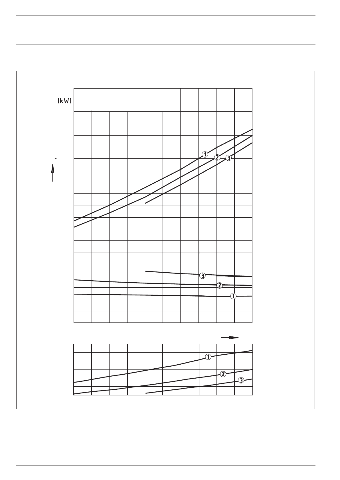
INSTALLATION
Specication
15.13 Output diagrams WPF 10 S basic
Ethylenglykol/Wassergemisch mit 33 Vol.% Ethylenglykol
20
1=Vorlauftemperatur 35 °C Volllast
2=Vorlauftemperatur 50 °C Volllast
3=Vorlauftemperatur 60 °C Volllast
15
HP
.
Q
10
Heat Output
HP
5
Power consumption P
0
-5 05
8
HP
7
6
5
4
3
2
Performance factor ε
1 Flow temperature 35 °C
2 Flow temperature 50 °C
3 Flow temperature 60 °C
10 15 20
Inlet temperature of Source Medium [°C]
°C
26�03�01�0260
66 | WPF basic www.stiebel-eltron.com
Page 67
INSTALLATION
Specication
15.14 Data table WPF 5-16 basic
Output details apply to new appliances with clean heat exchangers.
The power consumption figures for the integral auxiliary drives are maximum values and may vary subject to operating point.
The power consumption of the integral auxiliary drives is included in the output details of the heat pump (to EN 14511).
WPF 5 basic WPF 7 basic WPF 10 basic WPF 13 basic WPF 16 basic
230944 230945 230946 230947 230948
Heating output
Heating output at B0/ W35 (EN 14511) kW 5.88 7.64 9.7 12.59 16.64
Heating output at B10/W35 kW 7.62 9.82 12.44 16.37 20.88
Power consumption
Power consumption at B0/W35 (EN 14511) kW 1.36 1.70 2.22 2.85 4.00
Power consumption at B10/W35 kW 1.36 1.68 2.16 2.79 4.06
Max. power consumption, circulation pump on the heating side W 70 70 70 70 70
Power consumption, emergency/booster heater kW 8.8 8.8 8.8 8.8 8.8
Coeff icient of performance
COP at B0/W35 (EN 14511) 4.33 4.50 4.37 4.42 4.16
Coeff icient of performance at B10/W35 5.60 5.85 5.76 5.87 5.14
Sound emissions
Sound power level (EN 12102) dB(A) 46 47 51 53 53
Sound pressure level at a distance of 1m in a free field dB(A) 38 39 43 45 45
Sound pressure level at a distance of 5m in a free field dB(A) 24 25 29 31 31
Application limits
Max. permissible pressure MPa 0.3 0.3 0.3 0.3 0.3
Min. application limit on the heating side °C 15 15 15 15 15
Max. application limit on the heating side °C 60 60 60 60 60
Min. application limit, heat source °C -5 -5 -5 -5 -5
Max. application limit, heat source °C 20 20 20 20 20
Energy data
Energy efficiency class A+/A++ A+/A++ A+/A++ A+/A++ A+/A++
Electrical data
Frequency Hz 50 50 50 50 50
Control unit fuse/MCB A 1 x B 16 1 x B 16 1 x B 16 1 x B 16 1 x B 16
Compressor fuse/MCB A 3 x C 16 3 x C 16 3 x C 16 3 x C 16 3 x C 16
MCB/fuse protection, emergency/booster heater A 3 x B 16 3 x B 16 3 x B 16 3 x B 16 3 x B 16
Rated voltage, control unit V 230 230 230 230 230
Rated voltage, compressor V 400 400 400 400 400
Rated voltage, emergency/booster heater V 400 400 400 400 400
Control unit phases 1/N/PE 1/N/PE 1/N/PE 1/N/PE 1/N/PE
Compressor phases 3/N/PE 3/N/PE 3/N/PE 3/N/PE 3/N/PE
Emergency/booster heater phases 3/N/PE 3/N/PE 3/N/PE 3/N/PE 3/N/PE
Starting current (with/without starting current limiter) A 26/- 30/- 27/- 28/- 29/Versions
Refrigerant R410 A R410 A R410 A R410 A R410 A
Refrigerant charge kg 1.73 2 2.6 2.5 2.6
CO2 equivalent (CO2e) t 3.61 4.18 5.43 5.22 5.22
Global warming potential of the refrigerant (GWP100) 2088 2088 2088 2088 2088
Compressor oil Emkarate RL 32
Evaporator material 1.4401/Cu 1.4401/Cu 1.4401/Cu 1.4401/Cu 1.4401/Cu
Condenser material 1.4401/Cu 1.4401/Cu 1.4401/Cu 1.4401/Cu 1.4401/Cu
Circulation pump type on the heating side Stratos PARA
IP rating IP20 IP20 IP20 IP20 IP20
Dimensions
Height mm 960 960 960 960 960
Width mm 510 510 510 510 510
Depth mm 680 680 680 680 680
Weight
Weight kg 107 113 120 128 131
Connections
Connection on the heating side G 1 1/4 G 1 1/4 G 1 1/4 G 1 1/4 G 1 1/4
Connection on the heat source side G 1 1/4 G 1 1/4 G 1 1/4 G 1 1/4 G 1 1/4
3MAF
25/1-7
Emkarate RL 32
3MAF
Stratos PARA
25/1-7
Emkarate RL 32
3MAF
Stratos PARA
25/1-7
Emkarate RL 32
3MAF
Stratos PARA
25/1-7
Emkarate RL 32
3MAF
Stratos PARA
25/1-7
www.stiebel-eltron.com WPF basic | 67
Page 68
INSTALLATION
Specication
WPF 5 basic WPF 7 basic WPF 10 basic WPF 13 basic WPF 16 basic
Water quality requirements
Water hardness °dH ≤3 ≤3 ≤3 ≤3 ≤3
pH value (with aluminium fittings) 8.0-8.5 8.0-8.5 8.0-8.5 8.0-8.5 8.0-8.5
pH value (without aluminium fittings) 8.0-10.0 8.0-10.0 8.0-10.0 8.0-10.0 8.0-10.0
Chloride mg/l <30 <30 <30 <30 <30
Conductivity (softening) μS/cm <1000 <1000 <1000 <1000 <1000
Conductivity (desalination) μS/cm 20 -100 20 -100 20-100 20-100 20-100
Oxygen 8-12 weeks after filling (desalination) mg/l <0.1 <0.1 <0.1 <0.1 <0.1
Oxygen 8-12 weeks after filling (softening) mg/l <0.02 <0.02 <0.02 <0.02 <0.02
Heat transfer medium requirements on the heat source side
Ethylene glycol concentration, geothermal probe Vol.-% 25 25 25 25 25
Ethylene glycol concentration, geothermal collector Vol.-% 33 33 33 33 33
Values
Nominal design heating system flow rate at B0/W35 and 7K m³/h 0.71 0.91 1.22 1.58 2.08
Min. heating flow rate m³/h 0.5 0.64 0.86 1.1 1.45
Heating flow rate (EN 14511) for A7/W35, B0/W35 and 5 k m³/h 0.99 1.27 1.71 2.21 2.91
Flow rate on heat source side m³/h 1.4 1.9 2.2 3.1 3.8
Internal volume on the heating side l 2.4 2.8 3.4 3.4 3.4
Internal volume on the source side l 2.9 3.5 4.1 4.1 4.1
Available external pressure differential, heating system hPa 350 350 260 167 63
Pressure differential on the heat source side hPa 100 110 120 230 340
68 | WPF basic www.stiebel-eltron.com
Page 69
INSTALLATION
Specication
15.15 Datentabelle WPF 5-10 S basic
Output details apply to new appliances with clean heat exchangers.
The power consumption figures for the integral auxiliary drives are maximum values and may vary subject to operating point.
The power consumption of the integral auxiliary drives is included in the output details of the heat pump (to EN 14511).
WPF 5 S basic WPF 7 S basic WPF 10 S basic
074425 074426 220819
Heating output
Heating output at B0/ W35 (EN 14511) kW 5.80 7.80 9.90
Power consumption
Power consumption at B0/W35 (EN 14511) kW 1.35 1.78 2.20
Max. power consumption, circulation pump on the heating side W 93 93 93
Power consumption, emergency/booster heater kW 8.8 8.8 8.8
Coeff icient of performance
COP at B0/W35 (EN 14511) 4.30 4.40 4.50
Sound emissions
Sound power level (EN 12102) dB(A) 46 47 51
Sound pressure level at a distance of 1m in a free field dB(A) 38 39 43
Sound pressure level at a distance of 5m in a free field dB(A) 38 39 43
Application limits
Max. permissible pressure MPa 0.3 0.3 0.3
Min. application limit on the heating side °C 15 15 15
Max. application limit on the heating side °C 60 60 60
Min. application limit, heat source °C -5 -5 -5
Max. application limit, heat source °C 20 20 20
Energy data
Energy efficiency class A+/A++ A+/A++ A+/A++
Electrical data
Frequency Hz 50 50 50
Control unit fuse/MCB A 1 x B 16 1 x B 16 1 x B 16
Compressor fuse/MCB A 1 x C16 1 x C 25 1 x C 25
MCB/fuse protection, emergency/booster heater A 1 x C 35 1 x C 35 1 x C 35
Rated voltage, control unit V 230 230 230
Rated voltage, compressor V 230 230 230
Rated voltage, emergency/booster heater V 230 230 230
Control unit phases 1/N/PE 1/N/PE 1/N/PE
Compressor phases 1/N/PE 1/N/PE 1/N/PE
Emergency/booster heater phases 1/N/PE 1/N/PE 1/N/PE
Starting current (with/without starting current limiter) A 29/58 32/88 41/97
Versions
Refrigerant R410 A R410 A R410 A
Refrigerant charge kg 1.6 2.0 2.6
CO2 equivalent (CO2e) t 3.34 4.18 5.43
Global warming potential of the refrigerant (GWP100) 2088 2088 2088
Compressor oil Emkarate RL 32 3MAF Emkarate RL 32 3MAF Emkarate RL 32 3MAF
Evaporator material 1.4401/Cu 1.4401/Cu 1.4401/Cu
Condenser material 1.4401/Cu 1.4401/Cu 1.4401/Cu
Circulation pump type on the heating side Stratos PARA 25/1-7 Stratos PARA 25/1-7 Stratos PARA 25/1-7
Dimensions
Height mm 960 960 960
Width mm 510 510 510
Depth mm 680 680 680
Weight
Weight kg 107 113 120
Connections
Connection on the heating side G 1 1/4 G 1 1/4 G 1 1/4
Connection on the heat source side G 1 1/4 G 1 1/4 G 1 1/4
www.stiebel-eltron.com WPF basic | 69
Page 70
INSTALLATION
Specication
WPF 5 S basic WPF 7 S basic WPF 10 S basic
Water quality requirements
Water hardness °dH ≤3 ≤3 ≤3
pH value (with aluminium fittings) 8.0-8.5 8.0-8.5 8.0-8.5
pH value (without aluminium fittings) 8.0-10.0 8.0-10.0 8.0-10.0
Chloride mg/l <30 <30 <30
Conductivity (softening) μS/cm <1000 <1000 <1000
Conductivity (desalination) μS/cm 20 -100 20 -100 20-100
Oxygen 8-12 weeks after filling (desalination) mg/l <0.1 <0.1 <0.1
Oxygen 8-12 weeks after filling (softening) mg/l <0.02 <0.02 <0.02
Heat transfer medium requirements on the heat source side
Ethylene glycol concentration, geothermal probe Vol.-% 25 25 25
Ethylene glycol concentration, geothermal collector Vol.-% 33 33 33
Values
Nominal design heating system flow rate at B0/W35 and 7K m³/h 0.71 0.96 1.22
Min. heating flow rate m³/h 0.5 0.67 0.85
Heating flow rate (EN 14511) for A7/W35, B0/W35 and 5 k m³/h 1 1.34 1.71
Flow rate on heat source side m³/h 1.4 1.9 2.2
Internal volume on the heating side l 2.4 2.8 3.4
Internal volume on the source side l 2.9 3.5 4.1
Available external pressure differential, heating system hPa 350 350 260
Pressure differential on the heat source side hPa 100 110 120
15.16 Data table WPMiw
Electrical connection 1/N/PE ~ 230 V 50Hz
Power consumption VA 8
Relay breaking capacity A 2
IP rating IP1XB
Protection class II
Permissible ambient temperature during operation °C 0-50
Permissible ambient temperature during storage °C -30-60
Clock power reserve, day h >10
Sensor resistances, test resistance Ω 2000
Communication system RS232 (optical), CAN
Max. breaking capacity of relay output, buffer charging
pump
Max. breaking capacity of relay output, heating circuit
pump
Max. breaking capacity of relay output, mixer circuit
pump
Max. breaking capacity of relay output, DHW charging
pump
Max. breaking capacity of relay output, DHW circulation
pump
Max. breaking capacity of relay output, source pump A 2 (1.5)
Max. relay output breaking capacity 2nd heat generator
contact
Max. breaking capacity of relay output, mixer A 2 (1.5)
Max. total breaking capacity of all relay outputs A 10 (8)
A 2 (1.5)
A 2 (1.5)
A 2 (1.5)
A 2 (1.5)
A 2 (1.5)
A 2 (1.5)
70 | WPF basic www.stiebel-eltron.com
Page 71

GUARANTEE | ENVIRONMENT AND RECYCLING
Guarantee
The guarantee conditions of our German companies do not
apply to appliances acquired outside of Germany. In countries
where our subsidiaries sell our products a guarantee can only
be issued by those subsidiaries. Such guarantee is only granted if the subsidiary has issued its own terms of guarantee. No
other guarantee will be granted.
We shall not provide any guarantee for appliances acquired in
countries where we have no subsidiary to sell our products.
This will not aect warranties issued by any importers.
Environment and recycling
We would ask you to help protect the environment. After use,
dispose of the various materials in accordance with national
regulations.
www.stiebel-eltron.com WPF basic | 71
Page 72

g
y
Deutschland
STIEBEL ELTRON GmbH & Co. KG
Dr.-Stiebel-Straße 33 | 37603 Holzminden
Tel. 05531 702-0 | Fax 05531 702-480
[email protected]
www.stiebel-eltron.de
Australia
STIEBEL ELTRON Australia Pty. Ltd.
6 Prohasky Street | Port Melbourne VIC 3207
Tel. 03 9645-1833 | Fax 03 9645-4366
[email protected]
www.stiebel.com.au
Austria
STIEBEL ELTRON Ges.m.b.H.
Gewerbegebiet Neubau-Nord
Margaritenstraße 4 A | 4063 Hörsching
Tel. 07221 74600-0 | Fax 07221 74600-42
[email protected]
www.stiebel-eltron.at
Belgium
STIEBEL ELTRON bvba/sprl
't Hofveld 6 - D1 | 1702 Groot-Bijgaarden
Tel. 02 42322-22 | Fax 02 42322-12
[email protected]
www.stiebel-eltron.be
China
STIEBEL ELTRON (Guangzhou) Electric
Appliance Co., Ltd.
Rm 102, F1, Yingbin-Yihao Mansion, No. 1
Yingbin Road
Panyu District | 511431 Guangzhou
Tel. 020 39162209 | Fax 020 39162203
[email protected]
www.stiebeleltron.cn
Czech Republic
STIEBEL ELTRON spol. s r.o.
K Hájům 946 | 155 00 Praha 5 - Stodůlky
Tel. 251116-111 | Fax 235512-122
[email protected]
www.stiebel-eltron.cz
Finland
STIEBEL ELTRON OY
Kapinakuja 1 | 04600 Mäntsälä
Tel. 020 720-9988
[email protected]
www.stiebel-eltron.fi
Verkauf Tel. 05531 702-110 | Fax 05531 702-95108 | [email protected]
Kundendienst Tel. 05531 702-111 | Fax 05531 702-95890 | [email protected]
Ersatzteilverkauf Tel. 05531 702-120 | Fax 05531 702-95335 | [email protected]
France
STIEBEL ELTRON SAS
7-9, rue des Selliers
B.P 85107 | 57073 Metz-Cédex 3
Tel. 0387 7438-88 | Fax 0387 7468-26
[email protected]
www.stiebel-eltron.fr
Hungary
STIEBEL ELTRON Kft.
Gyár u. 2 | 2040 Budaörs
Tel. 01 250-6055 | Fax 01 368-8097
[email protected]
www.stiebel-eltron.hu
Japan
NIHON STIEBEL Co. Ltd.
Kowa Kawasaki Nishiguchi Building 8F
66-2 Horikawa-Cho
Saiwai-Ku | 212-0013 Kawasaki
Tel. 044 540-3200 | Fax 044 540-3210
[email protected]
www.nihonstiebel.co.jp
Netherlands
STIEBEL ELTRON Nederland B.V.
Daviottenweg 36 | 5222 BH 's-Hertogenbosch
Tel. 073 623-0000 | Fax 073 623-1141
[email protected]
www.stiebel-eltron.nl
Poland
STIEBEL ELTRON Polska Sp. z O.O.
ul. Działkowa 2 | 02-234 Warszawa
Tel. 022 60920-30 | Fax 022 60920-29
[email protected]
www.stiebel-eltron.pl
Russia
STIEBEL ELTRON LLC RUSSIA
Urzhumskaya street 4,
building 2 | 129343 Moscow
Tel. 0495 7753889 | Fax 0495 7753887
[email protected]
www.stiebel-eltron.ru
Slovakia
TATRAMAT - ohrievače vody s.r.o.
Hlavná 1 | 058 01 Poprad
Tel. 052 7127-125 | Fax 052 7127-148
[email protected]
www.stiebel-eltron.sk
Switzerland
STIEBEL ELTRON AG
Industrie West
Gass 8 | 5242 Lupfig
Tel. 056 4640-500 | Fax 056 4640-501
[email protected]
www.stiebel-eltron.ch
Thailand
STIEBEL ELTRON Asia Ltd.
469 Moo 2 Tambol Klong-Jik
Amphur Bangpa-In | 13160 Ayutthaya
Tel. 035 220088 | Fax 035 221188
[email protected]
www.stiebeleltronasia.com
United Kingdom and Ireland
STIEBEL ELTRON UK Ltd.
Unit 12 Stadium Court
Stadium Road | CH62 3RP Bromborough
Tel. 0151 346-2300 | Fax 0151 334-2913
[email protected]
www.stiebel-eltron.co.uk
United States of America
STIEBEL ELTRON, Inc.
17 West Street | 01088 West Hatfield MA
Tel. 0413 247-3380 | Fax 0413 247-3369
[email protected]
www.stiebel-eltron-usa.com
4<AMHCMN=jdbdgd>
Irrtum und technische Änderungen vorbehalten! | Subject to errors and technical changes! | Sous réserve
d‘erreurs et de modifications techniques! | Onder voorbehoud van ver
Salvo error o modificación técnica! | Excepto erro ou alteração técnica | Zastrzeżone zmian
ewentualne błędy | Omyly a technické změny jsou vyhrazeny! | A muszaki változtatások és tévedések jogát
fenntartjuk! |
technické zmeny sú vyhradené! Stand 9147
Отсутствие ошибок не гарантируется. Возможны технические изменения.
issingen en technische wijzigingen! |
techniczne i
| Chyby a
A 293136-40278-9267
B 293151-40278-9267
 Loading...