

STIEBEL ELTRON WPF 10 M, WPF 13 M, WPF 16 M, WPF 7 MS, WPF 10 MS Operation And Installation Manual
OPERATION AND INSTALLAT ION
BRINE | WATER HEAT PUMP
» WPF 10 M
» WPF 13 M
» WPF 16 M
» WPF 7 MS
» WPF 10 MS

2 | WPF M WWW.STIEBEL-ELTRON.COM
CONTENTS
SPECIAL INFORMATION
OPERATION
1. General information �����������������������������������������4
1.1 Further applicable documents �������������������������������� 4
1.2 Safety instructions ����������������������������������������������� 4
1.3 Other symbols in this documentation ����������������������� 4
1.4 Units of measurement ������������������������������������������ 4
1.5 Standardised output data �������������������������������������� 4
2. Safety ���������������������������������������������������������� 5
2.1 Intended use ������������������������������������������������������ 5
2.2 Safety instructions ����������������������������������������������� 5
2.3 Test symbols ������������������������������������������������������ 5
3. Appliance description ���������������������������������������5
4. Operation �����������������������������������������������������5
5. Maintenance and care ���������������������������������������5
6. Troubleshooting ����������������������������������������������5
6.1 Other problems �������������������������������������������������� 5
INSTALLATION
7. Safety ���������������������������������������������������������� 6
7.1 General safety instructions ������������������������������������ 6
7.2 Regulations, standards and instructions �������������������� 6
8. Appliance description ���������������������������������������6
8.1 Mode of operation ����������������������������������������������� 6
8.2 Standard delivery ������������������������������������������������ 6
9. Preparations �������������������������������������������������� 6
9.1 General information ��������������������������������������������� 6
9.2 Electrical installation�������������������������������������������� 7
9.3 Buffer cylinder ��������������������������������������������������� 7
10. Preparing for installation �����������������������������������7
10.1 Transport ���������������������������������������������������������� 7
10.2 Positioning �������������������������������������������������������� 7
10.3 Removing the casing panels ����������������������������������� 8
10.4 Installing the heat source system ���������������������������� 8
10.5 Heating water connection �������������������������������������� 9
10.6 Safety temperature controller for underfloor heating
system ������������������������������������������������������������10
10.7 Power supply ���������������������������������������������������� 10
10.8 Fitting casing components ������������������������������������ 13
11. Commissioning ��������������������������������������������� 13
11.1 Checks prior to commissioning the heat pump
manager ���������������������������������������������������������� 14
11.2 Commissioning the heat pump manager ������������������ 14
11.3 Heating curve adjustment ������������������������������������ 14
11.4 Appliance handover �������������������������������������������� 14
11.5 Operation and control ����������������������������������������� 14
12. Shutting down ���������������������������������������������� 14
13. Maintenance and cleaning �������������������������������� 15
14. Troubleshooting �������������������������������������������� 15
14.1 IWS controls ����������������������������������������������������� 15
15. Specification ������������������������������������������������ 16
15.1 Connections and dimensions ��������������������������������� 16
15.2 Wiring diagram WPF 10 M | WPF 13 M | WPF 16 M ������ 18
15.3 Wiring diagram WPF 7 MS | WPF 10 MS �������������������20
15.4 Output diagrams WPF 7 MS ����������������������������������22
15.5 Output diagrams WPF 10 M | WPF 10 MS ������������������ 24
15.6 Output diagrams WPF 13 M�����������������������������������26
15.7 Output diagrams WPF 16 M �����������������������������������28
15.8 Data table �������������������������������������������������������� 30
WARRANTY
ENVIRONMENT AND RECYCLING

SPECIAL INFORMATION
ENGLISH
WWW.STIEBEL-ELTRON.COM WPF M | 3
SPECIAL INFORMATION
- The appliance may be used by children aged 8
and up and persons with reduced physical, sensory or mental capabilities or a lack of experience provided that they are supervised or they
have been instructed on how to use the appliance
safely and have understood the resulting risks.
Children must never play with the appliance. Children must never clean the appliance or perform
user maintenance unless they are supervised.
- Only use a permanent connection to the power
supply. The appliance must be able to be separated from the power supply by an isolator that
disconnects all poles with at least 3mm contact
separation.
- Maintain the minimum clearances to ensure trouble-free operation of the appliance and facilitate
maintenance work.
- Maintenance work, such as checking the electrical safety, must only be carried out by a qualified
contractor.
- We recommend an annual inspection (to establish
the current condition of the system), and service
by a contractor if required (to return the system
into its original condition).
- The heat pump power supply must not be interrupted, even outside the heating season. Otherwise the system is at risk from frost.
- The heat pump manager automatically switches
the heat pump to summer or winter mode.
- If the heat pump and frost protection are completely switched off, drain the system on the
water side.
OPERATION
GENERAL INFORMATION
4 | WPF M WWW.STIEBEL-ELTRON.COM
OPERATION
1. General information
The chapter “Operation” is intended for appliance users and heating contractors.
The chapter “Installation” is intended for heating contractors.
Note
Read these instructions carefully before using the appliance and retain them for future reference.
Pass on the instructions to a new user if required.
1.1 Further applicable documents
Operating and installation instructions of the WPM heat
pump manager
Operating and installation instructions of all other com-
ponents in the system
1.2 Safety instructions
1.2.1 Structure of safety instructions
KEYWORD Type of risk
Here, possible consequences are listed that may result
from failure to observe the safety instructions.
Steps to prevent the risk are listed.
1.2.2 Symbols, type of risk
Symbol Type of risk
Injury
Electrocution
1.2.3 Keywords
KEYWORD Meaning
DANGER Failure to observe this information will result in serious
injury or death.
WARNING Failure to observe this information may result in serious
injury or death.
CAUTION Failure to observe this information may result in non-
serious or minor injury.
1.3 Other symbols in this documentation
Note
Notes are bordered by horizontal lines above and below
the text. General information is identified by the symbol
shown on the left.
Read these texts carefully.
Symbol
Damage to the appliance and environment
Appliance disposal
This symbol indicates that you have to do something. The ac-
tion you need to take is described step by step.
1.4 Units of measurement
Note
All measurements are given in mm unless stated otherwise.
1.5 Standardised output data
Explanations to determine and interpret the specified standardised
output data.
1.5.1 Standard: EN 14511
The output data specifically mentioned in text, diagrams and
technical datasheets has been calculated according to the test
conditions of the standard shown in the heading of this section.
Generally, these standardised test conditions will not fully meet
the conditions found at the installation site of the system user.
Depending on the chosen test method and the extent to which
this method deviates from the conditions defined in the norm
shown in the heading of this section, any deviations can have a
considerable impact.
Further factors that have an influence on the test values are the
measuring equipment, the system configuration, the age of the
system and the flow rates.
A confirmation of the specified output data can only be obtained
if the test conducted for this purpose is also performed in accordance with the conditions defined in the norm shown in the
heading of this section.
!
!
OPERATION
SAFETY
ENGLISH
WWW.STIEBEL-ELTRON.COM WPF M | 5
2. Safety
2.1 Intended use
The appliance is designed for central heating within the application limits given in the specification.
This appliance is designed for domestic use. It can be safely operated by untrained personnel. The appliance can also be used in a
non-domestic environment, e.g. in a small business, as long as it
is used in the same way.
Any other use beyond that described shall be deemed inappropriate. Observation of this document is also part of the correct use
of the unit. Any changes or conversions to the appliance void any
warranty. The appliance is designed to heat buildings.
2.2 Safety instructions
Observe the following safety instructions and regulations.
- The electrical installation and installation of the heating circuit must only be carried out by a recognised, qualified contractor or by our customer service engineers.
- Contractors are responsible for adherence to all currently applicable regulations during installation and commissioning.
- Operate the appliance only when fully installed and with all
safety equipment fitted.
- Protect the appliance from dust and dirt ingress during
building work.
!
WARNING Injury
The appliance may be used by children aged 8 and up
and persons with reduced physical, sensory or mental
capabilities or a lack of experience provided that they
are supervised or they have been instructed on how to
use the appliance safely and have understood the resulting risks. Children must never play with the appliance.
Children must never clean the appliance or perform user
maintenance unless they are supervised.
2.3 Test symbols
See type plate on the appliance.
3. Appliance description
The WPF...M is a heating heat pump designed to operate as a
ground source heat pump. The heat pump extracts energy from
the heat source medium, i.e. brine, at a low temperature level.
This extracted energy is then transferred to the heating water at a
higher level, enriched with the energy drawn by the compressor.
Subject to the heat source temperature, the heating water can be
heated up to a flow temperature of 60 °C.
Modular operation is feasible with the WPF..M.
4. Operation
The heat pump is exclusively controlled by the heat pump manager
WPM. Therefore, observe the instructions in chapter Operation,
in the operating and installation instructions of the heat pump
manager WPM.
5. Maintenance and care
!
Appliance and system damage
Maintenance work, such as checking the electrical safety,
must only be carried out by a qualified contractor.
A damp cloth is sufficient for cleaning all plastic and sheet steel
parts. Never use abrasive or corrosive cleaning agents.
Protect the appliance from dust and dirt ingress during building
work.
6. Troubleshooting
Fault Cause
Remedy
There is no hot water or
the heating system stays
cold.
The fuse/MCB has blown/
responded.
Check the fuse/MCB in
your fuse box/distribution panel.
6.1 Other problems
If you cannot remedy the fault, notify your heating contractor. To
facilitate and speed up your enquiry, please provide the serial
number from the type plate. The type plate is located on the front
at the top on the right or left hand side of the casing.
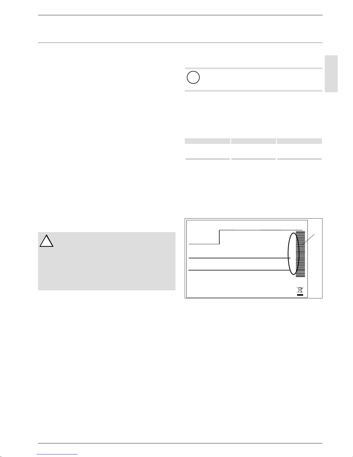
Sample type plate
Montageanweisung beachten! Dichtheit geprüft!
Made in Germany
*xxxxxxxxxxxxxxxxxx*
1
26�03�01�1570
1 Number on the type plate
6 | WPF M WWW.STIEBEL-ELTRON.COM
INSTALLATION
SAFETY
INSTALLATION
7. Safety
Only a qualified contractor should carry out installation, commissioning, maintenance and repair of the appliance.
7.1 General safety instructions
We guarantee trouble-free operation and operational reliability
only if the original accessories and spare parts intended for the
appliance are used.
7.2 Regulations, standards and instructions
Note
Observe all applicable national and regional regulations
and instructions.
8. Appliance description
8.1 Mode of operation
Environmental energy is extracted by the heat exchanger on the
heat source side (evaporator). Any energy extracted is transferred,
together with the energy drawn by the compressor drive, to the
heating water by a heat exchanger on the heating water side
(condenser). Subject to the heat load, the heating water can be
heated to +60°C. The DHW is heated via the internal indirect coil
inside the DHW cylinder.
8.2 Standard delivery
No other components are supplied with the appliance.
9. Preparations
9.1 General information
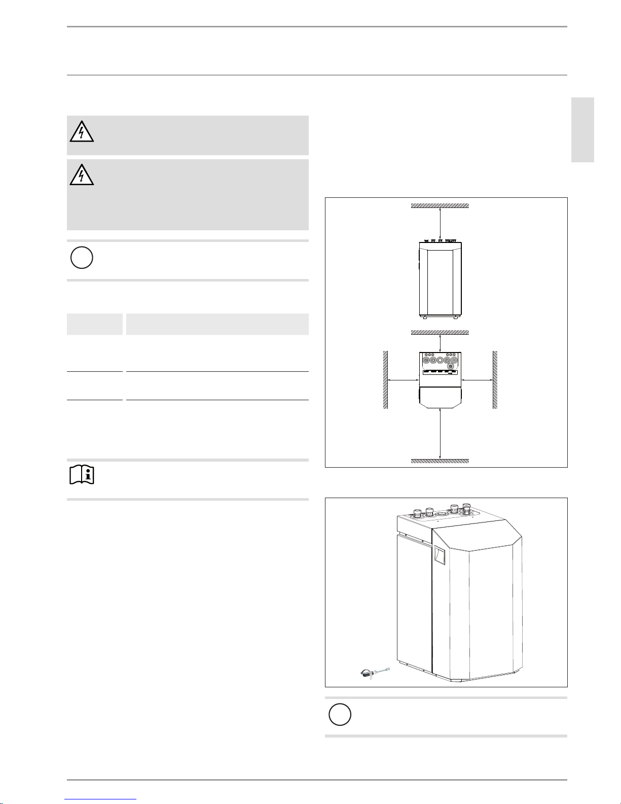
Note
The heat pump is designed for installation in interiors,
except in wet areas.
Never install the heat pump immediately below or adjacent to bedrooms. Insulate pipes through walls and ceilings against structureborne noise transmission.
The room in which the appliance is to be installed must meet the
following conditions:
- No risk from frost.
- Floor of load-bearing strength (for the equipment weight,
see specification).
- Horizontal, level and solid floor, as the equipment feet on the
heat pump are non-adjustable.
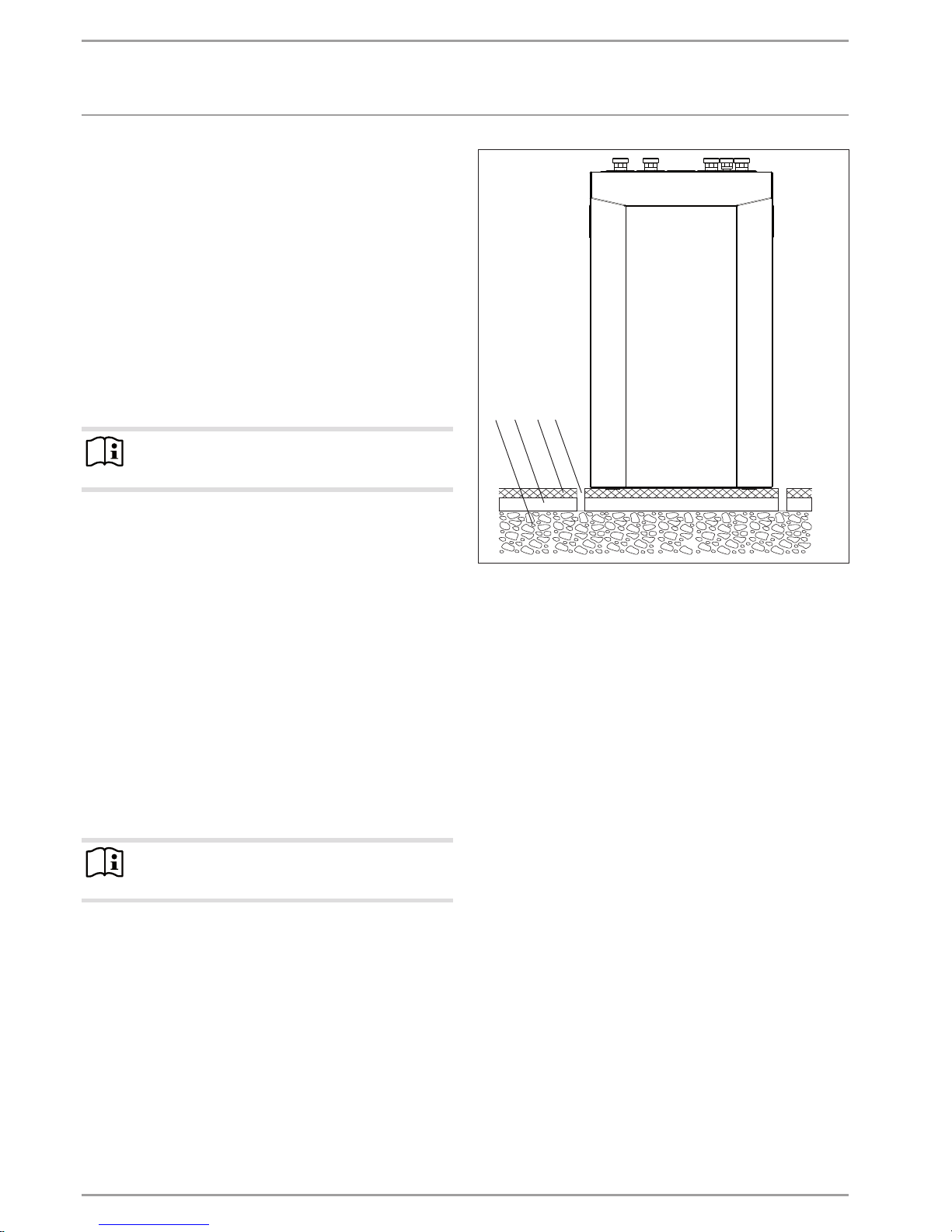
- For a quiet heat pump operation on floating screeds, recess
the screed and the anti-vibration insulation around the installation location of the heat pump.
1 432
26�03�01�0213
1 Concrete base
2 Impact sound insulation
3 Floating screed
4 Recess
- The room must not be subject to a risk of explosions arising
from dust, gases or vapours.
- The floor area of the installation room must be at least 3 m²,
and the room must provide a volume of at least 6 m³.
- When installing the heat pump in a boiler room together
with other heating equipment ensure, that the operation of
other heating equipment will not be impaired.
ENGLISH
WWW.STIEBEL-ELTRON.COM WPF M | 7
INSTALLATION
PREPARING FOR INSTALLATION
9.2 Electrical installation
WARNING Electrocution
Carry out all electrical connection and installation work
in accordance with national and regional regulations.
WARNING Electrocution
Only use a permanent connection to the power supply.
The appliance must be able to be isolated from the power
supply by an isolator that disconnects all poles with at
least 3mm contact separation. This requirement can be
met by contactors, circuit breakers, fuses etc.
!
Appliance damage
The specified voltage must match the mains voltage. Observe the type plate.
Use the following cable cross-sections subject to their fuse protection:
Fuse prot ection
Cable cross-section
C 16 A
2.5 mm²
1.5 mm² with only two live wires and routing on a wall or
in an electrical conduit on a wall.
C 25 A 6.0 mm² when routing in a wall.
4.0 mm² when routing a multi core line on a wall or in an
electrical conduit on a wall.
Provide separate fuses/MCB for the two power circuits of the appliance and the control unit.
The electrical specifications are given in the “Data table”. You
require aJ-Y(St)2x2x0.8mm² cable for the BUS.
Note
Provide separate fuses for the two power circuits of the
appliance and the control unit.
9.3 Buffer cylinder
A buffer cylinder is recommended to ensure a trouble-free appliance operation.
The buffer cylinder not only provides hydraulic separation of the
flow in the heat pump and heating circuit.
10. Preparing for installation
10.1 Transport
Transport the appliance in its packaging to protect it against
damage.
Protect the appliance against heavy impact during handling.
- Only allow the appliance to be tilted during transport for a
short time to one of its longitudinal sides.
The longer the appliance is tilted, the greater the distribution
of refrigerant oil in the system.
- Storage and transport at temperatures below -20°C and in
excess of +50°C are not permissible.
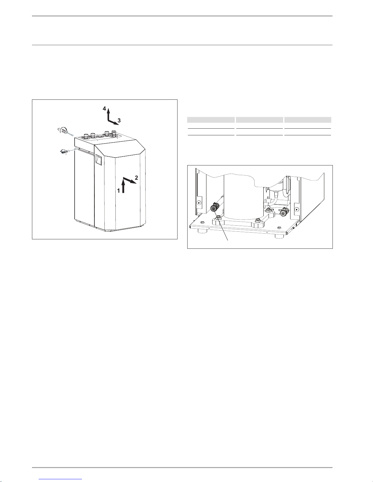
10.2 Positioning
Remove the packaging film and the top and side EPS
padding.
Tilt the appliance backwards slightly and remove it from the
pallet.
Position the appliance on the prepared substrate.
Observe the minimum clearances (see chapter “Connections
and dimensions”).
≥500
≥50
≥500
≥500
≥1000
D0000019327
Remove the six screws from the appliance plinth, and set
down the casing onto the floor.
6x
26�03�01�1573
!
Appliance damage
The casing must stand on the floor free of the refrigeration
unit. That means, the
six plinth screws must not be refitted.
8 | WPF M WWW.STIEBEL-ELTRON.COM
INSTALLATION
PREPARING FOR INSTALLATION
10.3 Removing the casing panels
When removing the front cover ensure that the cables that connect the heat pump manager to the control panel are not torn off.
The same applies to the earth connection which connects the front
cover to the casing electrically.
2x
4x
26�03�01�1574
10.4 Installing the heat source system
Design the heat source system for the ground source heat pump
in accordance with the technical guides.
Approved brine:
- Heat transfer medium as concentrate on an ethylene glycol
base, part no: 231109
- Heat transfer medium as concentrate on an ethylene glycol
base, part no: 16 16 96
10.4.1 Circulation pump and required flow rate
Use a circulation pump with compound-filled windings to supply
the brine, to prevent an earth short circuit through condensate in
the electrical part of the pump (cold water version).
Size the circulation pump in accordance with the system-specific
conditions, i.e. nominal flow rate and pressure drop must be taken
into consideration (see “Specification”).
An adequate flow rate must be safeguarded at every possible
brine temperature, i.e.:
Nominal flow rate at a brine temperature of 0°C with a tolerance
of +10 %.
10.4.2 Connection and filling with brine
Prior to connecting the heat pump, check the heat source circuit
for possible leaks, and flush thoroughly.
Calculate the volume of the heat source circuit. You can determine
the brine volume inside the heat pump under specific operating
conditions from the following table (see “Specification”).
The overall volume equals that of the required amount of brine
that should be mixed from undiluted ethylene glycol and water.
The chloride content of the water must not exceed 300 ppm.
Mixing ratio
The brine concentration varies when using a geothermal collector
or a geothermal probe as a heat source.
The mixing ratio can be found in the table below.
Ethylene glycol Water
Geothermal probe 25 % 75 %
Geothermal collector 33 % 67 %
Filling the brine circuit
Fill the brine circuit via the drain.
1
26�03�01�1606
1 Drain, brine side
After filling the system with brine and prior to commissioning,
open the drain until brine runs out of it. No water must remain in
the pipe run to the drain.
ENGLISH
WWW.STIEBEL-ELTRON.COM WPF M | 9
INSTALLATION
PREPARING FOR INSTALLATION
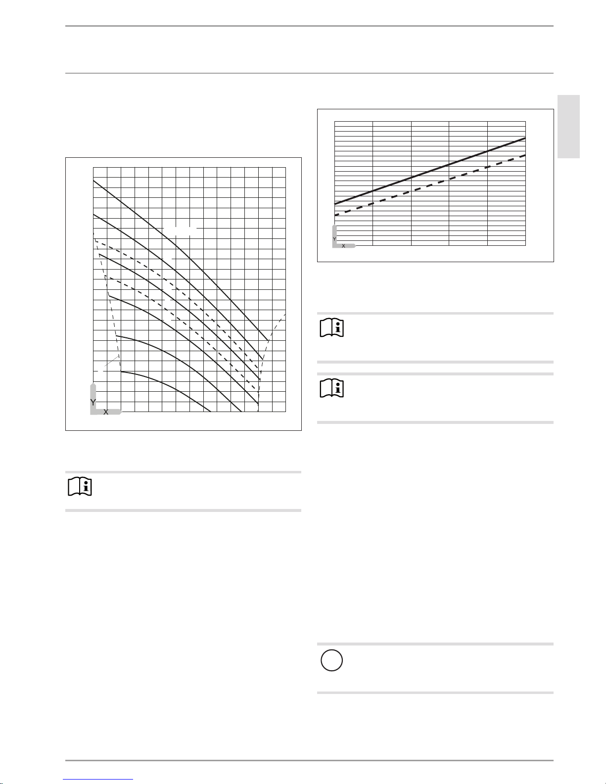
Check the brine concentration:
Determine the density of the ethylene glycol/water mixture,
e.g. with a hydrometer.
Using the actual density and temperature, you can check the actual
concentration in the diagram.
1,10
1,09
1,08
1,07
1,06
1,04
1,03
1,02
1,01
1,00
0,99
0,98
-20 0 20 40 60 80 100
50 Vol.-%
0
1,05
40
33
30
25
20
10
A
26�03�01�1914
X Temperature [°C]
Y Density [g/cm³]
A Frost protection [°C]
Note
The quoted details refer to ethylene glycol (see "Specification").
Thermally insulate all brine pipes with diffusion-proof material.
To prevent the transmission of noise, connect the heat source
circuit to the heat pump with flexible pressure hoses.
10.4.3 Checking the heat source flow rate
The heat source flow rate is set via the temperature differential of
the heat source circuit.
Calculate the temperature differential. For this, operate the
appliance in heating mode or DHW mode.
Max. temperature differential of heat source circuit
6
1
2
5
4
3
2
1
-5 0 5 10 15 20
84�03�01�0017
Y Max. temperature differential [K]
X Source inlet temperature [°C]
1 Heating flow 35 °C
2 Heating flow 50 °C
Note
At the WPM II, the source parameter in the commissioning
report must be set to “ethylene glycol” otherwise the frost
stat will stop the heat pump at temperatures below 7 °C.
Note
You can check the source outlet temperature on the heat
pump manager display under system menu item TEMPERATURES.
10.5 Heating water connection
The heat pump heating system must be installed by a qualified
contractor in accordance with the water installation drawings that
are part of the technical documents.
Thoroughly flush the pipework before connecting the heat
pump. Foreign bodies, such as welding pearls, rust, sand,
sealant etc. can impair the operational reliability of the heat
pump.
Connect the heat pump on the hot water side. Check for
tightness.
Ensure the correct connection of the heating flow and return.
Provide thermal insulation in accordance with applicable regulations.
For sizing the heating circuit, note the maximum available external
pressure differential.
10.5.1 Oxygen diffusion
!
Appliance damage
In underfloor heating systems, avoid open heating systems or the installation of steel pipes in conjunction with
plastic pipes that are permeable to oxygen.
Steel components such as internal cylinders, steel heating elements or steel pipes, can corrode as a result of oxygen diffusion in
open vented heating systems, of if plastic pipes that are permeable
to oxygen are used in underfloor heating systems.
10 | WPF M WWW.STIEBEL-ELTRON.COM
INSTALLATION
PREPARING FOR INSTALLATION
The products of corrosion, e.g. rusty sludge, can settle inside the
heat pump condenser and result in a lower output by reducing
the cross-section, or in a shutdown being activated by the high
pressure switch.
10.5.2 Second external heat generator
For dual mode heating systems, always connect the heat pump
into the return of the second heat generator (e.g. oil boiler).
High heating water temperature: In dual mode heating systems,
the return water from the second heat generator can flow through
the heat pump, immediately after it has been switched off, with
a max. temperature of 60 °C. The temperature may be 70 °C no
sooner than ten minutes after the heat pump has been shut down.
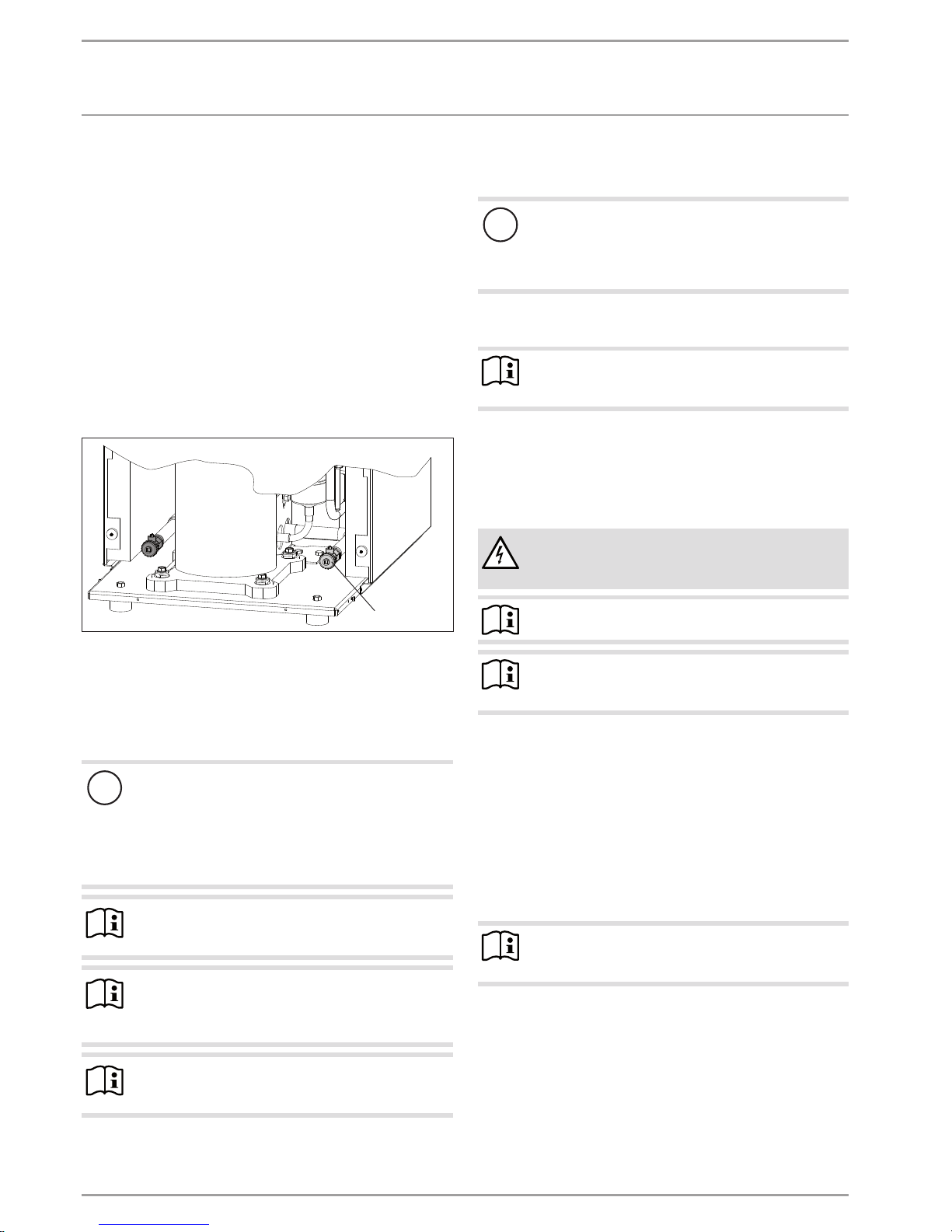
10.5.3 Filling the heating system
Fill the heating system via the drain valve.
26�03�01�1606
1
1 Drain, heating side
Water quality
A fill water analysis must be available prior to charging the system. This may, for example, be requested from the relevant water
supply utility.
!
Material losses
To avoid damage as a result of scaling, it may be necessary to soften or desalinate the fill water. The fill water
limits specified in chapter "Specification / Data table"
must always be observed.
Recheck these limits 8-12 weeks after commission-
ing and as part of annual system maintenance.
Note
With conductivity of >1000μS/cm, desalination treatment
is recommended in order to avoid corrosion.
Note
Suitable appliances for water softening and desalinating,
as well as for charging and flushing heating systems, can
be obtained via trade suppliers.
Note
If you treat the fill water with inhibitors or additives, the
same limits as for desalination apply.
10.5.4 Venting the heating system
Vent the pipework thoroughly.
10.6 Safety temperature controller for underfloor
heating system
!
Material losses
In case of failure, in order to prevent an excessively high
flow temperature in the underfloor heating system, we
generally recommend the use of a safety temperature
controller to limit the system temperature.
10.7 Power supply
Note
Observe the heat pump manager operating and installation instructions
Only qualified electricians must carry out the installation in accordance with these instructions.
Permission to connect the appliance may need to be obtained from
your local power supply utility.
Observe chapter “Preparing the electrical installation”.
DANGER Electrocution
Before any work, isolate the appliance from the power
supply at the control panel.
Note
The terminals are located in the appliance control panel.
Note
If the appliance is sealed, observe chapter “Removing
the casing parts”.
Use appropriate cables in accordance with local regulations for
all connections.
Open the control panel’s cover flap. To do so, remove the fix-
ing screws on the side at the top of the control panel.
Route all connecting cables and sensor leads through the en-
tries provided at the top of the back panel (see chapter “Connections and dimensions”).
Route all cables and leads through the strain relief fittings.
Connect cables according to the following diagrams.
Then check the function of the strain relief fittings.
Note
When closing the appliance, observe chapter “Fitting the
casing parts”.
ENGLISH
WWW.STIEBEL-ELTRON.COM WPF M | 11
INSTALLATION
PREPARING FOR INSTALLATION
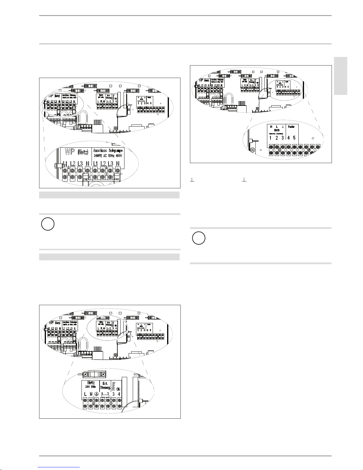
10.7.1 Electrical connection WPF (three-phase)
Terminals X3: Appliance and brine pump
26�03�01�1595
Heat pump power supply (compressor)
L1, L2, L3, N, PE (3/N/PE~400 V 50 Hz)
!
Please note:
The compressor must only rotate in one direction. Change
the direction of rotation by interchanging two phases, if
the fault NO POWER appears in the WPM display when
the compressor starts.
Brine pump power supply
L1, L2, L3, N, PE (3/N/PE~400 V 50 Hz)
After connecting all electrical cables, refit and seal the cover over
the mains terminal strip.
Terminals X4: Control
26�03�01�1596
Mains supply: L, N, PE (1/N/PE ~230 V 50 Hz )
Terminals X2: Low voltage
26�03�01�1597
H BUS high
L BUS Low
BUS ground
“ + “ BUS “ + “
Sensor No function
Circulation pumps
Connect the circulation pumps in accordance with the specifications in the technical guides.
!
Appliance damage
If external high efficiency circulation pumps are used,
never switch these directly.
Use an external relay with a breaking capacity of at least
10 A/250 V AC.
 Loading...