

STIEBEL ELTRON WPF 16, WPF 04 cool, WPF 05 cool, WPF 07 cool, WPF 13 cool Operation And Installation
...
OPERATION AND INSTALLAT ION
Brine | water heat pump
» WPF 04
» WPF 05
» WPF 07
» WPF 10
» WPF 13
» WPF 16
» WPF 04 cool
» WPF 05 cool
» WPF 07 cool
» WPF 10 cool
» WPF 13 cool
» WPF 16 cool
» WPF 05 S
» WPF 07 S
» WPF 10 S
» WPF 13 S

2 |WPF | WPF cool www.stiebel-eltron.com
CONTENTS
SPECIAL INFORMATION
OPERATION
1. General information _________________________________________4
1.1 Safety instructions ����������������������������������������������� 4
1.2 Other symbols in this documentation ����������������������� 4
1.3 Units of measurement ������������������������������������������ 4
1.4 Standardised output data �������������������������������������� 4
2. Safety __________________________________________________________ 5
2.1 Intended use ������������������������������������������������������ 5
2.2 Safety instructions ����������������������������������������������� 5
2.3 Test symbols ������������������������������������������������������ 5
3. Appliance description _______________________________________5
3.1 Special features of the WPF ... cool �������������������������� 5
3.2 Accessories �������������������������������������������������������� 6
4. Operation _____________________________________________________7
4.1 Controls ������������������������������������������������������������ 7
4.2 Entering parameters �������������������������������������������� 8
4.3 Selecting operating modes ������������������������������������ 9
4.4 Picture symbols �������������������������������������������������� 9
5. Menu structure _____________________________________________ 10
5.1 Info menu �������������������������������������������������������� 10
5.2 DIAGNOSIS menu ����������������������������������������������� 12
5.3 PROGRAMS menu ���������������������������������������������� 13
5.4 Settings menu ��������������������������������������������������� 15
6. Maintenance and care _____________________________________ 22
7. Troubleshooting ____________________________________________ 22
7.1 Other problems ������������������������������������������������� 22
INSTALLATION
8. Safety ________________________________________________________ 23
8.1 General safety instructions ����������������������������������� 23
8.2 Instructions, standards and regulations ������������������� 23
9. Appliance description _____________________________________ 23
9.1 Mode of operation ���������������������������������������������� 23
9.2 Special features of the WPF...cool ���������������������������23
9.3 Standard delivery ����������������������������������������������� 23
9.4 Accessories �������������������������������������������������������23
10. Preparations ________________________________________________ 23
10.1 Electrical installation������������������������������������������� 24
11. Installation __________________________________________________ 25
11.1 Handling ���������������������������������������������������������� 25
11.2 Siting �������������������������������������������������������������� 25
11.3 Removing the casing parts ����������������������������������� 25
11.4 Installing the heat source system ��������������������������� 25
11.5 Heating water connection ������������������������������������� 27
11.6 Oxygen diffusion ������������������������������������������������ 28
11.7 Filling the heating system ������������������������������������ 28
11.8 Venting the heating system ����������������������������������� 29
11.9 DHW heating ����������������������������������������������������� 29
11.10 Operation with buffer cylinder ������������������������������� 29
11.11 Fitting the push-fit connectors ������������������������������� 29
12. Power supply _______________________________________________ 30
12.1 General �����������������������������������������������������������30
12.2 Power supply ����������������������������������������������������30
12.3 Sensor installation ���������������������������������������������� 33
12.4 Safety temperature controller for underfloor heating
system STB-FB �������������������������������������������������� 33
12.5 Remote control FE 7 �������������������������������������������� 33
12.6 Remote control FEK ��������������������������������������������34
12.7 Uponor DEM WP module �������������������������������������� 34
12.8 Internet Service Gateway ISG �������������������������������� 34
13. Commissioning _____________________________________________ 34
13.1 Checks before commissioning�������������������������������� 34
13.2 Heating curve adjustment during commissioning �������35
13.3 Commissioning menu ������������������������������������������ 35
13.4 WPM3i commissioning report �������������������������������� 38
14. Settings _____________________________________________________ 40
14.1 Standard settings ����������������������������������������������� 40
14.2 Heating and DHW programs ���������������������������������� 40
14.3 Appliance handover �������������������������������������������� 40
15. Shutting down ______________________________________________ 41
16. Troubleshooting ____________________________________________ 41
16.1 Fault display ����������������������������������������������������� 41
16.2 Fault message ��������������������������������������������������� 41
16.3 Resetting the high limit safety cut-out ��������������������� 42
16.4 Resetting the compressor high limit safety cut-out ����� 42
16.5 Fault table �������������������������������������������������������� 43
17. Maintenance ________________________________________________ 44
18. Specification ________________________________________________ 45
18.1 Dimensions and connections ��������������������������������� 45
18.2 Wiring diagram WPF 04 | 04 cool | WPF 05 | 05 cool�����46
18.3 Wiring diagram WPF07| 07cool| WPF10| 10cool|
WPF13| 13cool| WPF16| 16cool �������������������������48
18.4 Wiring diagram WPF 05 S | WPF 07 S | WPF 10 S |
WPF 13 S ���������������������������������������������������������� 50
18.5 Output diagrams WPF 04 | WPF 04 cool �������������������� 52
18.6 Output diagrams WPF 05 | WPF 05 cool �������������������� 54
18.7 Output diagrams WPF 07 | WPF 07 cool �������������������� 56
18.8 Output diagrams WPF 10 | WPF 10 cool �������������������� 58
18.9 Output diagrams WPF 13 | WPF 13 cool �������������������� 60
18.10 Output diagrams WPF 16 | WPF 16 cool �������������������� 62
18.11 Output diagrams WPF 05 S ����������������������������������� 64
18.12 Output diagrams WPF 07 S ����������������������������������� 66
18.13 Output diagrams WPF 10 S �����������������������������������68
18.14 Output diagrams WPF 13 S ����������������������������������� 70
18.15 Data table WPF .... ���������������������������������������������� 72
18.16 Data table WPF .... cool ���������������������������������������� 74
18.17 Data table WPF .... S ������������������������������������������� 76
GUARANTEE
ENVIRONMENT AND RECYCLING

SPECIAL INFORMATION
www.stiebel-eltron.com WPF | 3
SPECIAL INFORMATION
- The appliance may be used by children aged8
and up and persons with reduced physical, sensory or mental capabilities or a lack of experience
and know-how, provided that they are supervised
or they have been instructed on how to use the
appliance safely and have understood the resulting risks. Children must never play with the appliance. Children must never clean the appliance
or perform user maintenance unless they are
supervised.
- Use a permanent connection to the power supply.
Ensure the appliance can be separated from the
power supply by an isolator that disconnects all
poles with at least 3mm contact separation.
- Maintain the minimum clearances to ensure trouble-free operation of the appliance and facilitate
maintenance work.
- In dual mode operation, return water from the
second heat generator may flow through the heat
pump. Please note that the return water temperature may be a maximum of 60°C.
- Active cooling is only possible in conjunction with
a suitable hydraulic circuit. Set parameter COOLING to ACTIVE COOLING. The COOLING parameter
will only be shown if a FEK or FE 7 remote control
is connected. Cooling mode is only possible in
summer mode.
- The WPF...S is not suitable for cooling.
- The air outlet in the knurled cap of the quick-action air vent valve must not point towards the
MFG PCB. Close the quick-action air vent valve
again after venting.
- Maintenance work, such as checking the electrical safety, must only be carried out by a qualified
contractor.
- We recommend an annual inspection (to establish
the system’s current condition), and maintenance
by a qualified contractor if required (to return the
system to the desired condition).
- Never interrupt the power supply, even outside
the heating period. The system’s active frost protection is not guaranteed if the power supply is
interrupted.
- There is no need to shut the system down in
summer. The heat pump manager has an automatic summer/winter changeover.
OPERATION
General information
4 |WPF | WPF cool www.stiebel-eltron.com
OPERATION
1. General information
The chapters „Special Information“ and „Operation“ are intended
for both the user and qualified contractors.
The chapter "Installation" is intended for qualified contractors.
Note
Read these instructions carefully before using the appliance and retain them for future reference.
Pass on the instructions to any new user if required.
1.1 Safety instructions
1.1.1 Structure of safety instructions
!
KEYWORD Type of risk
Here, possible consequences are listed that may result
from failure to observe the safety instructions.
Steps to prevent the risk are listed.
1.1.2 Symbols, type of risk
Symbol Type of risk
Injury
Electrocution
Burns
(burns, scalding)
1.1.3 Keywords
KEYWORD Meaning
DANGER Failure to observe this information will result in serious
injury or death.
WARNING Failure to observe this information may result in serious
injury or death.
CAUTION Failure to observe this information may result in non-seri-
ous or minor injury.
1.2 Other symbols in this documentation
Note
General information is identified by the symbol shown
on the left.
Read these texts carefully.
Symbol Meaning
Material losses
(appliance and consequential losses, environmental pollution)
Appliance disposal
This symbol indicates that you have to do something. The ac-
tion you need to take is described step by step.
1.3 Units of measurement
Note
All measurements are given in mm unless stated otherwise.
1.4 Standardised output data
Explanations to determine and interpret the specified standardised
output data.
1.4.1 Standard: EN 14511
The output data specifically mentioned in text, diagrams and
technical datasheets has been calculated according to the test
conditions of the standard shown in the heading of this section.
Generally, these standardised test conditions will not fully meet
the conditions found at the installation site of the system user.
Depending on the chosen test method and the extent to which
the selected method deviates from the conditions described in
the standard shown in the heading of this chapter, any deviations
can have a considerable impact.
Further factors that have an influence on the test values are the
measuring equipment, the system configuration, the age of the
system and the flow rates.
A confirmation of the specified output data can only be obtained
if the conditions applicable to the relevant test match those of the
standard shown in the heading of this chapter.
!
!
OPERATION
Safety
www.stiebel-eltron.com WPF | WPF cool | 5
2. Safety
2.1 Intended use
The appliance is designed for:
- heating rooms
- DHW heating
Observe the operating limits listed in chapter "Specification".
This appliance is intended for domestic use. It can be used safely
by untrained persons. The appliance can also be used in a non-domestic environment, e.g. in a small business, as long as it is used
in the same way.
Any other use beyond that described shall be deemed inappropriate. Observation of these instructions and of instructions for any
accessories used is also part of the correct use of this appliance.
2.2 Safety instructions
- The electrical installation and installation of the heating circuit must only be carried out by a recognised, qualified contractor or by our customer service engineers.
- The qualified contractor is responsible for adherence to all
currently applicable instructions during installation and
commissioning.
- Operate the appliance only when fully installed and with all
safety equipment fitted.
- Protect the appliance from dust and dirt ingress during
building work.
!
WARNING Injury
The appliance may be used by children aged 8 and up and
persons with reduced physical, sensory or mental capabilities or a lack of experience and know-how provided
that they are supervised or they have been instructed
on how to use the appliance safely and have understood
the resulting risks. Children must never play with the
appliance. Children must never clean the appliance or
perform user maintenance unless they are supervised.
Note
Do not change any system-specific settings at the control
unit. Your contractor has set the control unit to match
the local conditions for your building and your individual
requirements. The system-specific parameters are protected by a code scan so they cannot be unintentionally
modified.
The parameters that serve to match the appliance to your
personal requirements are not protected by a code scan.
2.3 Test symbols
See type plate on the appliance.
3. Appliance description
The appliance is a heating heat pump suitable for operation as a
brine/water heat pump. The heat pump extracts energy from the
heat source medium at a low temperature level. This extracted
energy is then transferred to the heating water at a higher level,
enriched by the electric energy drawn by the compressor. Subject
to the heat source temperature, the heating water can be heated
up to a flow temperature of 65 °C.
The heating circuit pump, a multi function assembly (MFG) with
safety assembly and a three-way valve have been integrated in the
appliance for diverting the flow either to the heating circuit or the
DHW circuit. DHW is heated by pumping the heating water, which
has been heated by the heat pump, through an indirect coil in the
DHW cylinder, where it transfers its energy to the DHW.
The appliance is equipped with an electric emergency/booster
heater (DHC). If the dual mode point can no longer be maintained
in mono mode operation, the electric emergency/booster heater is activated to safeguard heating operation and the provision
of high DHW temperatures. In such cases, the electric emergency/booster heater is activated in mono energetic operation as a
booster heater.
The appliance is regulated by an integral, weather-compensated
return temperature controller (WPM3i heat pump manager).
The WPM3i also regulates the DHW heating to the required temperature. If either the high pressure sensor or the hot gas limiter
of the heat pump responds during DHW heating, then DHW heating
will automatically be completed by an integral electric emergency/
booster heater, subject to the DHW learning function being disabled. If the DHW learning function is enabled, DHW heating will
cease and the set DHW value is overwritten with the actual DHW
temperature achieved.
The WPM3i also controls the integral electric emergency/booster
heater. No other heat generator can be switched.
3.1 Special features of the WPF ... cool
An additional heat exchanger and three-way valve for changing
over between heating and cooling are integrated into the WPF...
cool.
The living space is cooled by the brine being pumped though the
additional heat exchanger, where the energy from the heating
water is extracted and passed to the cooler zones underground.
The compressor does not run during cooling.
OPERATION
Appliance description
6 |WPF | WPF cool www.stiebel-eltron.com
3.2 Accessories
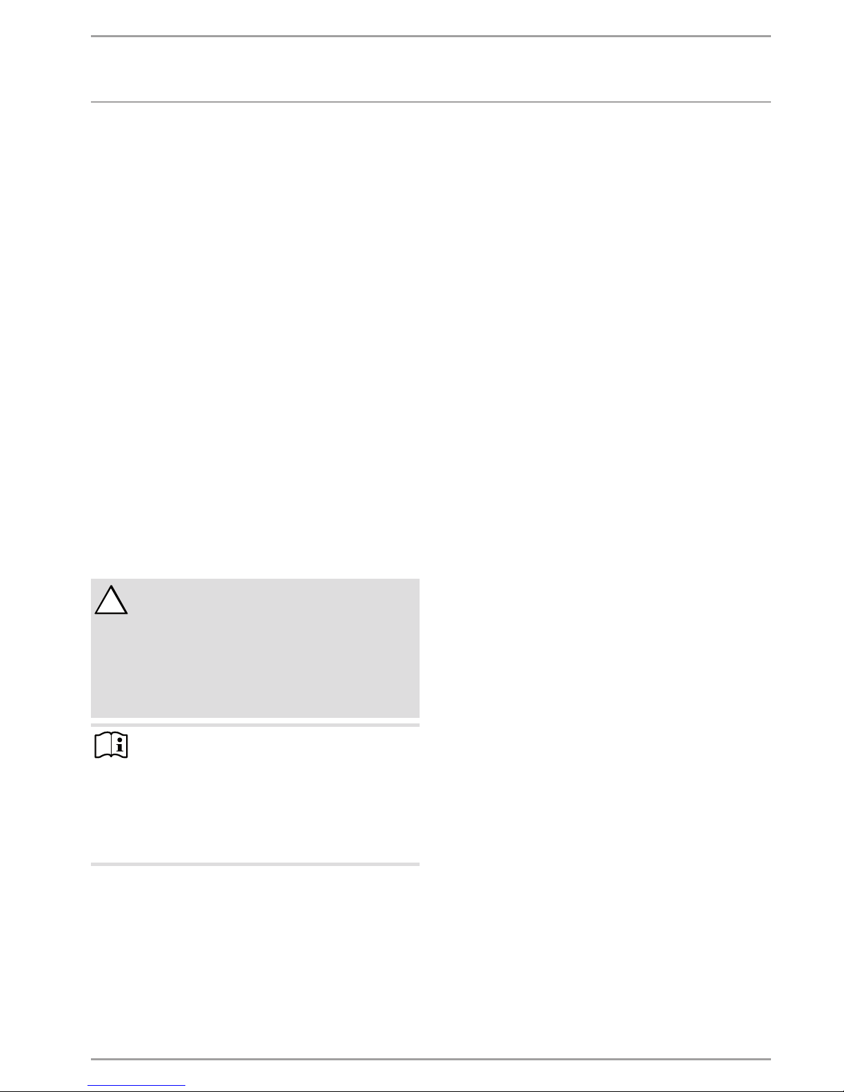
3.2.1 FE7 remote control
PIC00000609
The FE7 remote control allows you to:
- Change the set room temperature for heating in heating circuit1 or2 by ±5°C.
- Change the operating mode.
The FE7 remote control features the following controls:
- Rotary selector for changing the set room temperature
- Rotary selector with the following positions
-
Automatic mode
-
Constant setback mode
-
Constant day mode
Note
The remote control is only active in the automatic mode
of the heat pump manager.
You can set the temperature for heating times in automatic mode at the remote control.
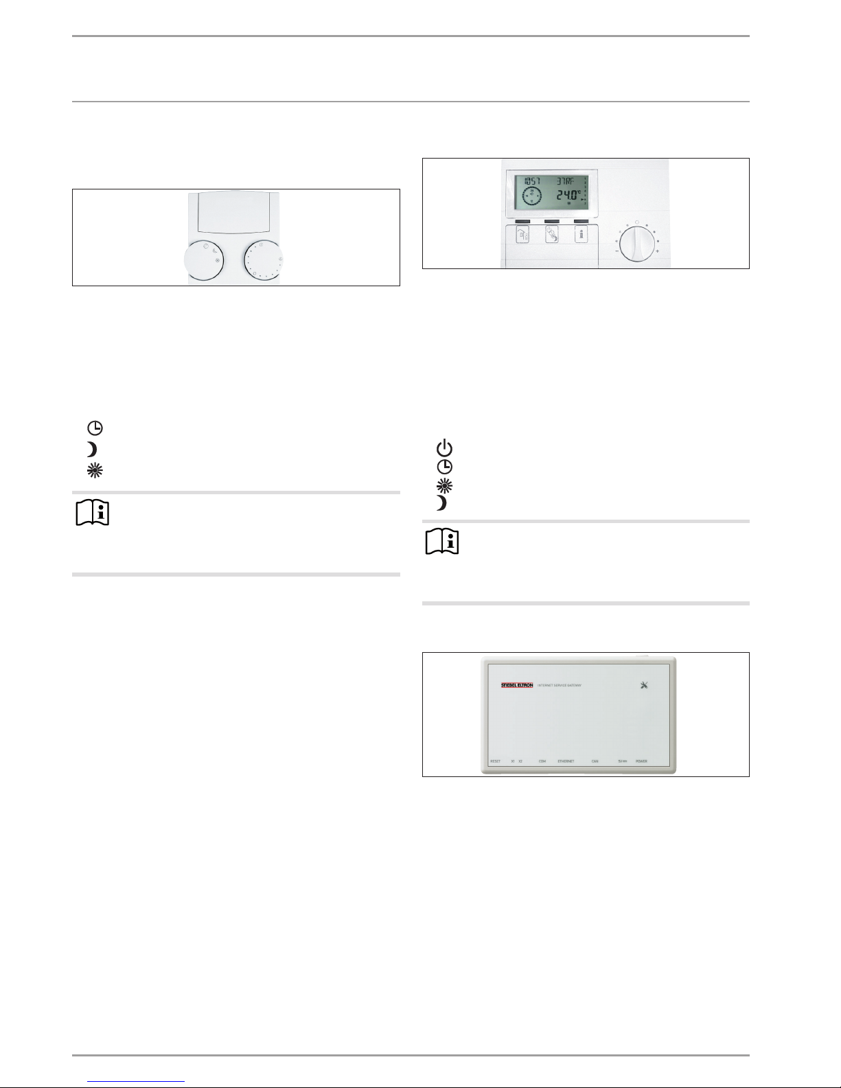
3.2.2 FEK remote control
PIC00000704
The FEK remote control allows you to:
- Change the set room temperature for heating in heating circuit1 or2 by ±5°C.
- Change the operating mode.
The FEK features the following controls:
- Rotary selector for changing the set room temperature
- „Away“ button
- „Info“ button
- Button for selecting the following operating modes:
-
Standby mode
-
Automatic mode
-
Constant day mode
-
Constant setback mode
Note
If the FEK is preselected for a specific heating circuit,
the heating curve, room temperature and heating program parameters are not shown at the WPM3i heat pump
manager.
3.2.3 Internet Service Gateway (ISG)
PIC00001002
The Internet Service Gateway (ISG) is an Ethernet gateway in a
wall mounted casing and is connected into the LAN (local area
network).
It enables the convenient operation, adjustment and checking of
heat pump system data via the browser of a computer, laptop or
tablet in the local home network.
If required by the customer, appliance data can be automatically
transmitted to the appliance manufacturer‘s SERVICEWELT portal
via the internet.
Via SERVICES you can access additional options such as system
operation on the go with a smartphone as well as remote setting
of parameters and remote diagnosis, etc.
You can find the current services on our homepage.
OPERATION
Operation
www.stiebel-eltron.com WPF | WPF cool | 7
4. Operation
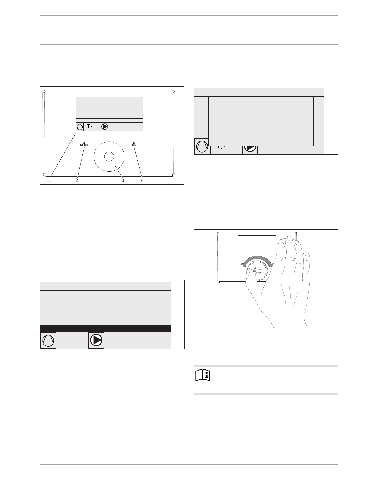
4.1 Controls
OKMENU
D0000064711
1 32 4
WEDNE SDAY 12 JUN 13 10:23 TI ME
OUTSIDE TEMPERATURE
ACTUAL DH W TEMP
27.0 °C
35.0 °C
28.0 °C
ACTUAL RETURN TEMP
ECO MODE
1 Display
2 MENU key
3 Scroll wheel
4 OK key
You control the system with the programming unit of the heat
pump manager. Use the scroll wheel and the MENU and OK keys
to navigate through the menu structure.
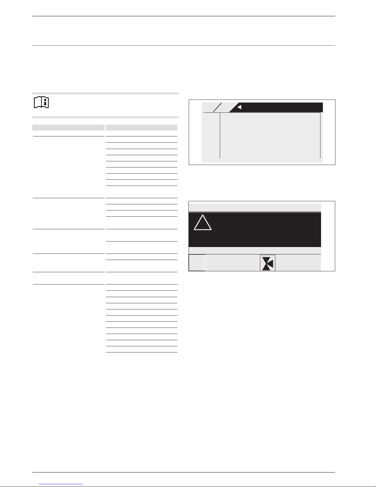
4.1.1 Display
The programming unit display shows the current state of the system and provides messages and information.
Start screen
WEDNESDAY 12 JUN 13 10:23 TIME
OUTSIDE TEMPERATURE
ACTUAL DHW TEMP
27.0 ° C
35.0 °C
28.0 °C
ACTUAL RETURN TEMP
26�04�01�0292
ECO MODE
1 Date and time
2 Temperature display
3 Operating mode
4 System status picture symbols
The start screen is divided into four sections. The top field displays
the date and time. The field below displays the outside temperature along with the actual DHW temperature and the actual return
temperature. The third section is for selecting and displaying the
operating modes. In the fourth section, picture symbols indicate
the current system state.
Activation
If the scroll wheel and keys/fields are not used for 20minutes,
the programming unit is locked.
WEDNESDAY 12 JUN 13 10:23 TIME
OUTSIDE TEMPERATURE
ACTUAL DHW TEMP
27. 0 ° C
35.0 °C
28.0 °C
ACTUAL RETURN TEMP
ECO MODE
To activate please
for 3 seconds
press MENU.
26�04�01�0292
Touch the MENU key for three seconds to enable the pro-
gramming unit.
Selection indicator
A highlighter within the menu structure indicates the current position at all times. This displays the selected menu item with a
dark background. The current menu level is displayed at the top
of the display.
4.1.2 Scroll wheel
D0000064710
The scroll wheel comprises a sensor that is touch-sensitive. There
is one key array each to the left and right of the scroll wheel. All
required appliance functions are controlled and checked with the
scroll wheel and the keys.
Note Sensor responsiveness
Wearing gloves, wet hands or a damp programming unit
impede the recognition of your touch and the execution
of the action you require.
In the MAIN MENU/COMMISSIONING menu, your contractor can set
the sensitivity to touch using the parameter TOUCH SENSITIVITY.
OPERATION
Operation
8 |WPF | WPF cool www.stiebel-eltron.com
Circular movement
Move one finger clockwise over the scroll wheel to move the highlighter downwards or to the right in the list, depending on how
the menu options are arranged. An anti-clockwise rotation moves
the highlighter to the left or upwards in the list.
Alongside navigation within the menu structure, the scroll wheel
is used to set parameters. Clockwise rotation increases values.
Anti-clockwise rotation decreases values.
4.1.3 Keys
Note
Press the keys only briefly to initiate the required action.
If a key is touched for too long, the programming unit
does not respond.
MENU key
The MENU key has two functions:
- From the start screen, touch the MENU key to navigate to the
first of 5 menu structure levels.
- Touch the MENU key when within the menu structure to return to the previous menu level.
OK key
The OK key has four functions:
- From the start screen, touch the OK key to activate the required operating mode previously selected using the scroll
wheel.
- Within the menu structure, touching the OK key confirms the
selected menu option and takes you one menu level down.
- If you are already at parameter level, touching the OK key
saves the currently set parameter.
- At every menu level, you will see the entry BACK. If you select BACK, you move a level higher in the menu.
If, for longer than five minutes, there is no user action, no rotation
or
MENU or OK are not pressed, the programming unit display
automatically jumps back to the start screen.
Parameter changes made before this which had not yet been confirmed with OK are lost. The parameters retain the values saved
so far.
4.1.4 Contractor access
Note
Some menu options are protected by a code and can only
be viewed and adjusted by a qualified contractor.
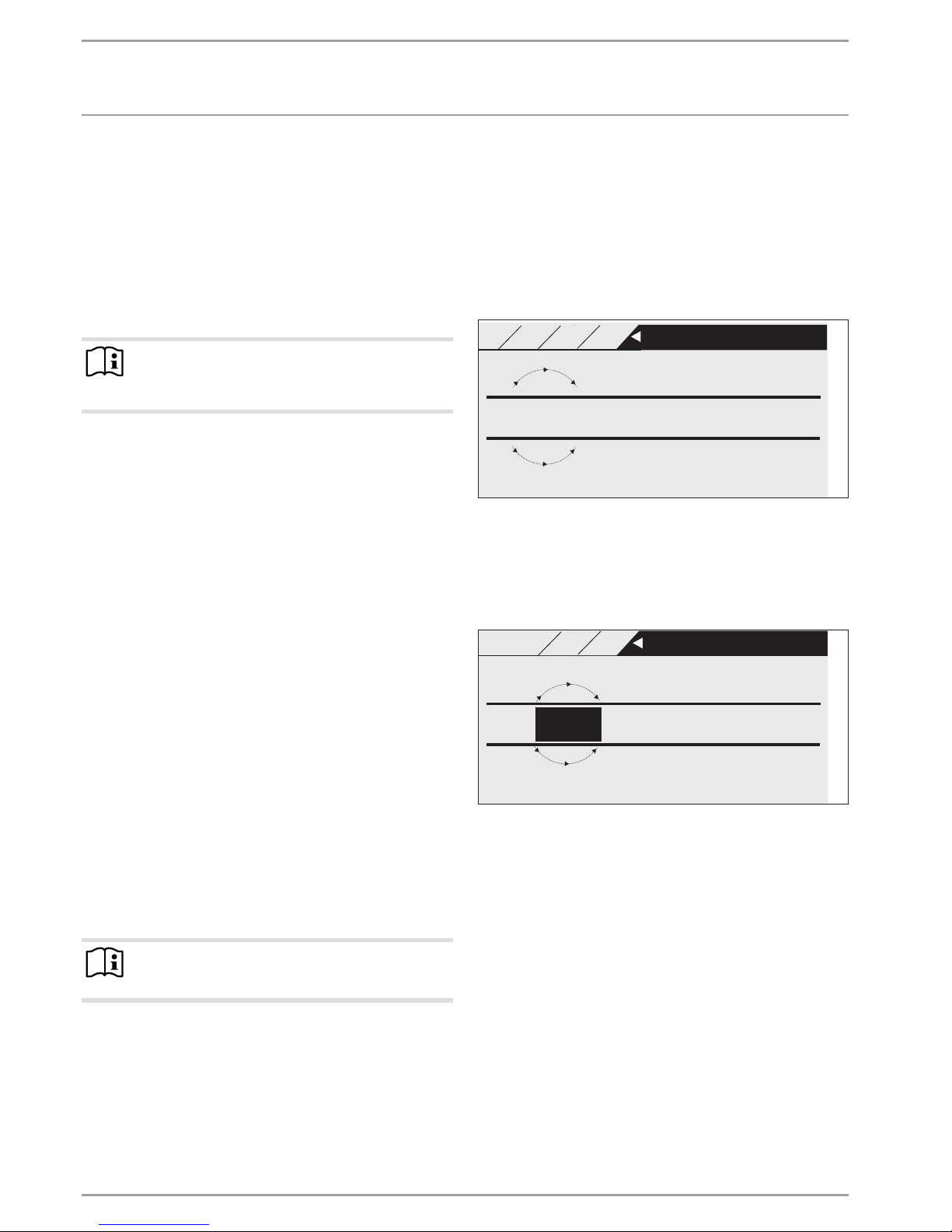
4.2 Entering parameters
Parameters are changed by rotating the scroll wheel. To save the
new value, touch OK.
If you want to cancel the entry, touch
MENU. The parameter re-
tains the previously saved value.
Example 1
Adjusting the set room temperature.
+
21.7
-
MAIN
SET
°C SET ROOM TEMP COMFORT
26�04�01�0347
HEATING HC1
HEATING HC1
SET ROOM TEMP CO
21
To enter set temperatures, a number surrounded by a circle appears on the display. This indicates that you can change the value
by turning the scroll wheel.
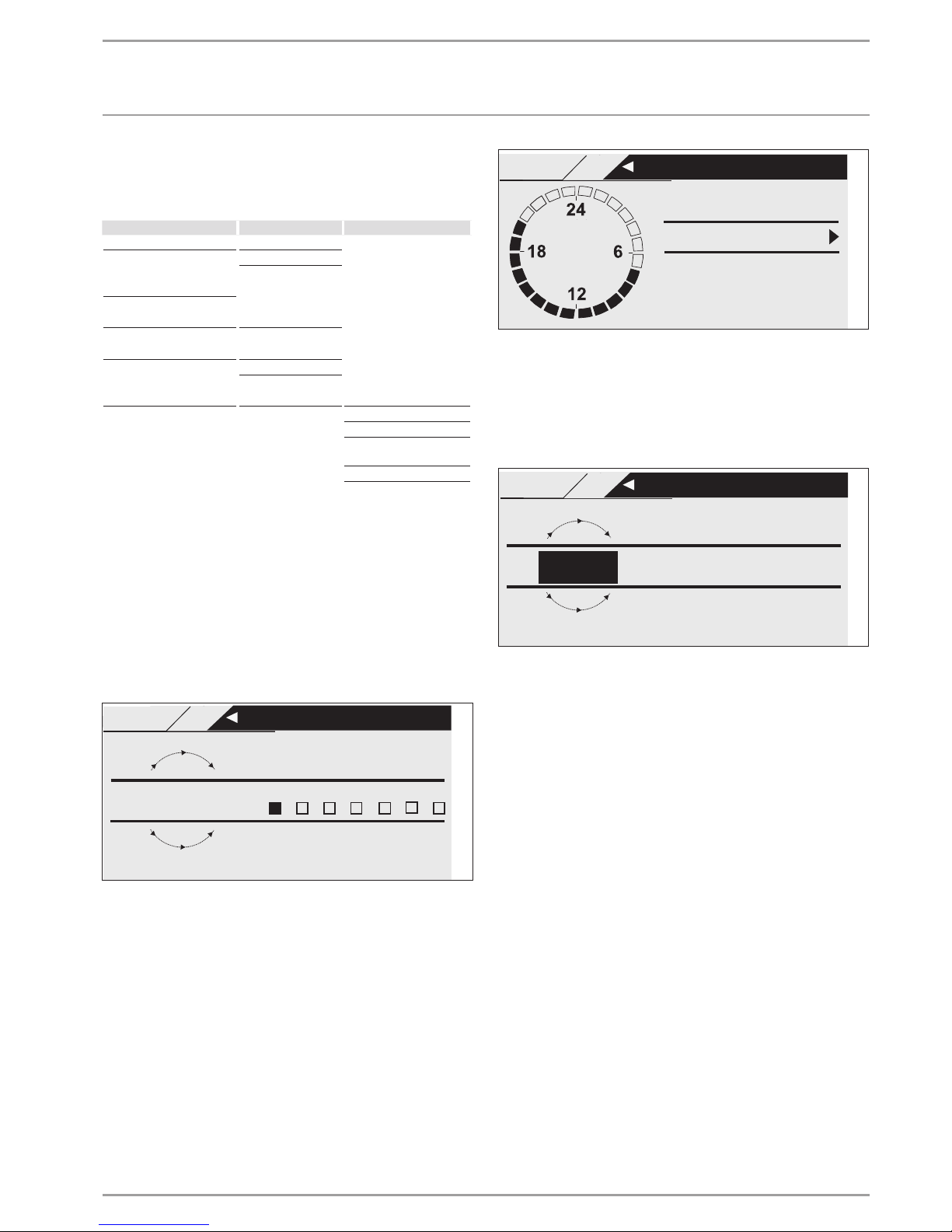
Example 2
Setting the time and date.
15.
09 08:23
Day Month Year Hour Minute
Jun
26�04�01�0296
MAIN
SET
GEN HC1
TIME HC1
TIME / DATE
13
On activation, the highlighter is over the position MONTH. Confirm
with OK. Set the current month with the scroll wheel and confirm
with OK. A calendar page is displayed. Move the highlighter to the
required day with the scroll wheel and confirm with OK. The new
value is saved when you confirm with OK. Set the year, hours and
minutes the same way.
OPERATION
Operation
www.stiebel-eltron.com WPF | WPF cool | 9
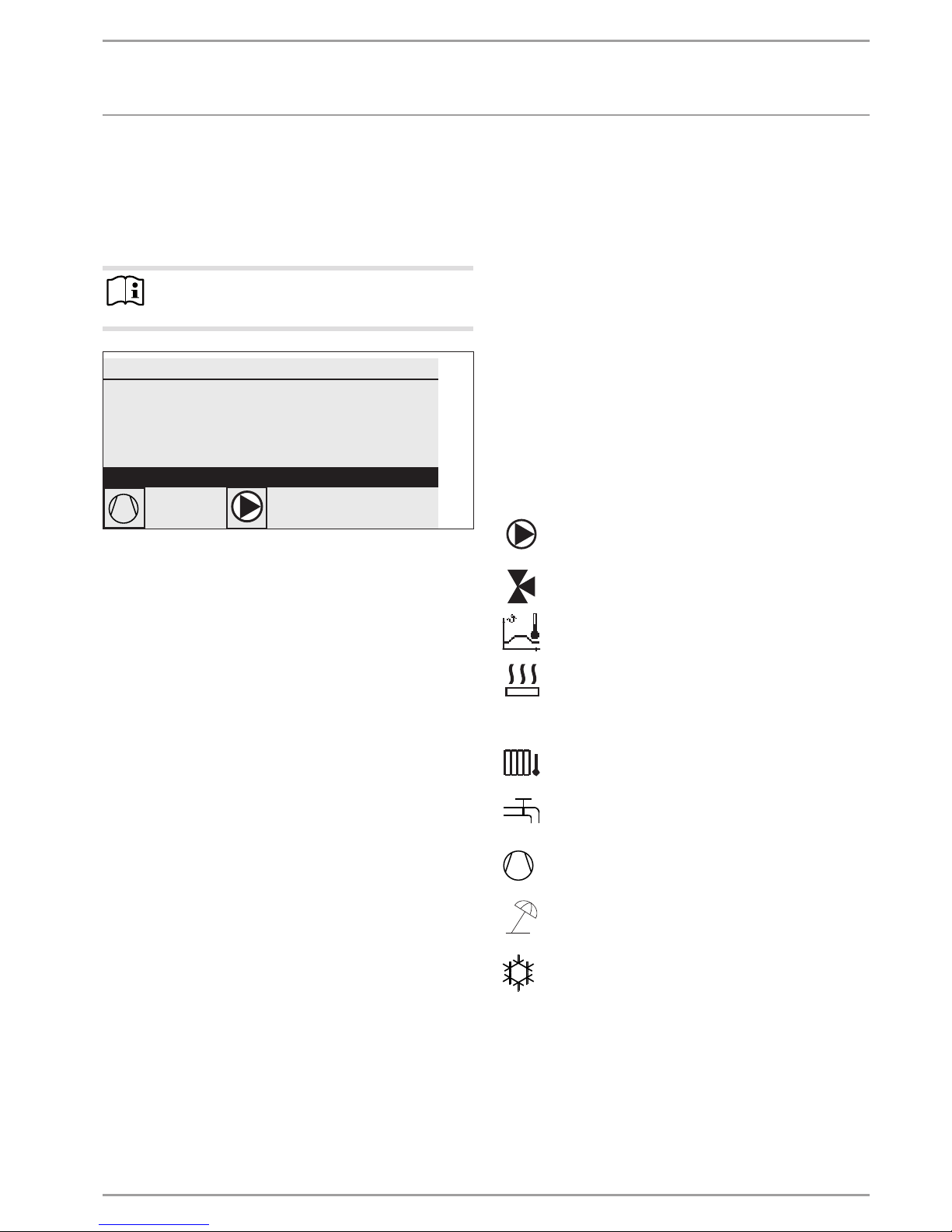
4.3 Selecting operating modes
If you enable the start screen, the current operating mode is
displayed. If you want to select another operating mode, turn
the scroll wheel. You run through the list of possible operating
modes. The current suggestion (list entry) is shown in the shaded
selection field.
Note
To change the appliance to this new operating mode,
confirm with OK.
WEDNESDAY 12 JUN 13 10:23 TIME
OUTSIDE TEMPERATURE
ACTUAL DHW TEMP
27.0 ° C
35.0 °C
28.0 °C
ACTUAL RETURN TEMP
26�04�01�0292
ECO MODE
Since you always navigate to a new operating mode from the
currently enabled one, you may have to turn anti-clockwise. All
operating modes, apart from DHW mode, apply to central heating
and DHW.
Standby mode
Frost protection is activated for heating and DHW mode. The set
DHW value is fixed at 10 °C, the set heating flow value is calculated
based on a set room value of 5 °C.
Application: During prolonged periods of absence, e.g. holidays.
Programming mode
Heating in line with the time switch program (applies to heating
circuits1 and2). Changeover between Comfort temperature and
ECO temperature.
DHW heating in line with the time switch program; changeover
between Comfort temperature and ECO temperature.
The remote control is only active in this operating mode.
Application: When DHW and central heating are required.
Comfort mode
The heating circuit (HC) is constantly held at the comfort temperature (HC1 and HC2). DHW heating according to time switch
program.
Application: Low energy houses without setback mode.
ECO mode
The heating circuit is constantly held at the ECO temperature (applicable to HC1 and HC2). DHW heating according to time switch
program.
Application: During weekends away.
DHW mode
DHW heating is regulated by a time switch program. If a time
program is enabled, the water inside the DHW cylinder is heated
to the set comfort temperature. At all other times, the water is
heated to the set ECO temperature. Frost protection is activated
for heating operation.
Application: The heating season has ended; only DHW should be
provided (summer mode).
Emergency mode
In this operating mode, the heat pump is blocked. The BH stages
(electric booster stages) of the emergency/booster heater heat
according to the selected clock program for heating and DHW
operation.
Inform your contractor immediately.
4.4 Picture symbols
At the lower edge of the display, symbols provide information
about the current appliance operating status.
Heating circuit pump: The pump symbol is displayed
when a heating circuit pump is running.
Mixer circuit pump: The mixer symbol is displayed
when a mixer circuit pump is running.
Heat-up program:
This symbol is displayed when the heat-up program runs.
Electric emergency/booster heater:
The electric emergency/booster heater has started. This
occurs, for example, when the outside temperature has
fallen below the dual mode point.
Central heating: The heating symbol is displayed when
the appliance is in heating mode.
DHW heating: This symbol tells you that the heat pump
is heating DHW.
Compressor: The symbol is displayed when the com-
pressor is running.
Summer mode: The symbol is displayed when the appliance is in summer mode.
Cooling: The symbol is displayed when the appliance is
in cooling mode.
OPERATION
Menu structure
10 |WPF | WPF cool www.stiebel-eltron.com
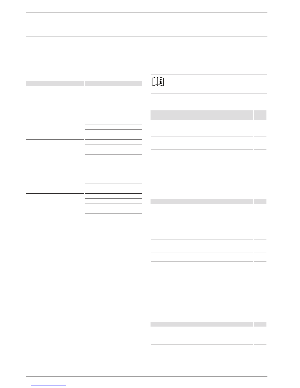
5. Menu structure
After activating the programming unit, you can use the scroll
wheel to select other operating modes or the menu key to jump
to a level from which you can navigate to a specific appliance
parameter.
Level 1 Level 2
INFO SYSTEM
HEAT PUMP
DIAGNOSIS SYSTEM STATUS
HEAT PUMP STATUS
SYSTEM
INTERNAL CALCULATION
FAULT LIST
RELAY TEST SYSTEM
PROGRAMS HEATING PROGRAM
DHW PROGRAM
PARTY PROGRAM
HOLIDAY PROGRAM
HEAT-UP PROGRAM
SETTINGS GENERAL
HEATING
DHW
COOLING
COMMISSIONING ENTER CODE
LANGUAGE
SOURCE
HEATING
DHW
COMPRESSOR
EMERGENCY OPR
HEAT PUMP RESET
FAULT LIST RESET
SYSTEM RESET
5.1 INFO MENU
In the INFO menu you can check comparisons of set and actual
values for temperatures, flow rates and pressures of the heating
system and the heat pump.
Note
Please note that actual and set values can only be displayed if the appropriate sensors are connected.
5.1.1 INFO SYSTEM
Level 3
Room temperatures
ACTUAL TEMPERATURE FE7
Actual room temperature for heating circuit 1 (HC1) or heating circuit
2 (HC2)
(will only be displayed if the FE7 remote control is connected)
°C
SET TEMPERATURE FE7
Set room temperature for heating circuit 1 or heating circuit 2
(will only be displayed if the FE7 remote control is connected)
°C
ACTUAL TEMPERATURE FEK
Actual room temperature for heating circuit 1 or heating circuit 2
(will only be displayed if the FEK remote control is connected)
°C
SET TEMPERATURE FEK
Set room temperature for heating circuit 1 or heating circuit 2
(will only be displayed if the FEK remote control is connected)
°C
REL HUMIDITY %
DEW POINT TEMPERATURE
Dew point temperature (will only be displayed if the FEK remote control is connected)
°C
Heating
OUTSIDE TEMPERATURE °C
ACTUAL TEMPERATURE HC 1
Actual heating circuit temperature heating circuit 1
°C
SET TEMPERATURE HC 1
Set heating circuit temperature heating circuit 1 (HC1). Fixed temperature is displayed with set value control.
°C
ACTUAL TEMPERATURE HC 2
Actual heating circuit temperature heating circuit 2
°C
SET TEMPERATURE HC 2
Set heating circuit temperature heating circuit 2 (HC2). Fixed temperature is displayed with set value control.
°C
ACTUAL FLOW TEMPERATURE HP
Actual heat pump flow temperature
°C
ACTUAL FLOW TEMPERATURE BH
Actual flow temperature of electric emergency/booster heater
°C
ACTUAL RETURN TEMP °C
SET FIXED TEMPERATURE °C
ACTUAL BUFFER TEMPERATURE
Actual buffer cylinder temperature
°C
SET BUFFER TEMPERATURE
Set buffer cylinder temperature
°C
HEATING PR ES bar
FLOW R ATE l/min
SYST FROST PRO
System frost protection temperature
°C
DHW
ACTUAL TEMPERATURE
Actual DHW temperature
°C
SET TEMPERATURE
Set DHW temperature
°C
FLOW R ATE l/min

OPERATION
Menu structure
www.stiebel-eltron.com WPF | WPF cool | 11
Level 3
Cooling
ACTUAL TEMPERATURE FAN °C
SET TEMPERATURE FAN °C
ACTUAL TEMPERATURE AREA °C
SET TEMPERATURE AREA °C
Electric booster heater
DUAL MODE TEMP HEATING
Heating dual mode point
°C
APPLICATION LIMIT HEATING
Heating application limit
°C
DUAL MODE TEMP DHW
DHW dual mode point
°C
APPLICATION LIMIT DHW
DHW application limit
°C
Source
SOURCE TEMPERATURE °C
SOURCE TEMPERATURE MIN °C
SOURCE PRESSURE bar
5.1.2 INFO HEAT PUMP
Hinweis
The power consumption is calculated on the basis of refrigerant circuit pressure. This calculation is inappropriate for billing purposes. Together with the amount of heat
it is used for a rough energy statement.
Level 3
Process data
HOT GAS TEMPERATURE
Compressor outlet temperature
°C
HIGH PRESSURE bar
LOW PRESSURE bar
Amount of heat
COMPRESSOR HEATING DAY
Compressor heat amount in heating mode since 00:00 h today in
kWh.
kWh
COMPRESSOR HEATING TOTAL
Total amount of compressor heat generated in heating mode in
MWh.
MWh
COMPRESSOR DHW DAY
Compressor heat amount in DHW mode since 00:00 h today in kWh.
kWh
COMPRESSOR DHW TOTAL
Total amount of compressor heat generated in DHW mode in MWh.
MWh
BH HEATING TOTAL
Total amount of heat generated by the electric emergency/booster
heater in heating mode in MWh.
MWh
BH DHW TOTAL
Total amount of heat generated by the electric emergency/booster
heater in DHW mode in MWh.
MWh
POWER CONSUMP TION
COMPRESSOR HEATING DAY
Electrical output of compressor in heating mode since 0:00 h today.
kWh
COMPRESSOR HEATING TOTAL
Total electrical output of compressor in heating mode.
MWh
COMPRESSOR DHW DAY
Electrical output of compressor in DHW mode since 0:00 h today.
kWh
COMPRESSOR DHW TOTAL
Total electrical output of compressor in DHW mode
MWh
Runtimes in hours
HEATING COMPRESSOR 1
Runtime of compressor 1 in heating mode.
Hours
DHW COMPRESSOR 1
Runtime of compressor 1 in DHW mode.
Hours
COOLING COMPRESSOR 1
Runtime of compressor 1 in cooling mode.
Hours
NHZ 1
Runtime of electric emergency/booster heater in booster stage 1.
Hours
NHZ 2
Runtime of electric emergency/booster heater in booster stage 2.
Hours
NHZ 1/2
Runtime of electric emergency/booster heater in booster stages 1
and 2.
Hours
STAR TS
COMPRESSOR
OPERATION
Menu structure
12 |WPF | WPF cool www.stiebel-eltron.com
5.2 DIAGNOSIS menu
For heating system and heat pump troubleshooting and analysis,
all important process data and bus subscribers can be queried
under DIAGNOSIS and a relay test can be carried out.
Note
The menu item RELAY TEST SYSTEM is protected by a
code and can only be accessed by a qualified contractor.
Level 2 Level 3
SYSTEM STATUS BUFFER CHARGING PUMP
DHW VALVE
HTG CIRC PUMP
MIXER PUMP
MIXER OPEN
MIXER CLOSED
SOURCE PUMP
COOLING MODE
POWER BLOCKED
HEAT PUMP STATUS REM IDLE TIME in minutes
COMPRESSOR
NHZ 1
NHZ 2
SYSTEM BUS SUBSCRIBER
HEAT PUMP TYPE
INTERNAL CALCULATION INTERVAL
LIVE STAGES
FAULT LIST see fault table
RELAY TEST SYSTEM BUFFER CHARGING PUMP
DHW VALVE
HTG CIRC PUMP
MIXER PUMP
MIXER OPEN
MIXER CLOSED
NHZ 1
NHZ 2
NHZ 3
SOURCE PUMP
COOLING MODE
DRAIN HYD MFG
5.2.1 Fault list
In the fault list, you receive an overview of the faults most recently
registered by the appliance. The fault list contains up to 20 fault
messages. The display, however, can show only 2. Turn the scroll
wheel to access the other entries in the fault list.
MAIN DIAG
FAULT LIST 1/1
01. SENSOR BREAK E 71
10:26 14.JUN 13
02. MIN SRCE TEMP
17:45 25.JUN 13
5.2.2 Fault message
If the appliance registers a fault, this is clearly displayed with the
message shown below.
COMFORT MODE
!
FAULT
SENSOR BREAK E 71
TUESDAY 14.JUN 13 16:27 TIME
If more than one fault occurs, the most recent one is shown continuously. Please inform your contractor.
5.2.3 Relay test
You can control all relay outputs of the controller from here.
OPERATION
Menu structure
www.stiebel-eltron.com WPF | WPF cool | 13
5.3 PROGRAMS menu
Here you can set all times for heating, DHW, holiday and party
modes and you can also start the heat-up program.
Level 2 Level 3 Level 4
HEATING PROGRAM HEAT CIRCUIT 1
HEAT CIRCUIT 2
DHW PROGRAM
PARTY PROGRAM HOURS
HOLIDAY PROGRAM HOLS BEGINNING
HOLIDAYS ENDING
HEAT-UP PROGRAM ON / OFF LOW END TEMPERATURE
TEMP. RISE PERIOD
MAXIMUM TEMPERATURE
MAX TEMPERATURE DU-
RAT ION
RISE PER DAY
5.3.1 Heating program
In the menu item HEATING PROGRAM you can determine when
and how often the appliance heats to the set comfort values for
heating circuit1 and heating circuit2. At all other times, the appliance heats to the set ECO value. You can select the set values under
menu item SETTINGS/HEATING/HEATING CIRCUIT1 or SETTINGS/
HEATING/HEATING CIRCUIT2. There follows an explanation of how
to define a time program.
First, select the days on which you want to enable the HEATING
function:
+
-
26�04�01�0301
Monday
Mon
MAIN
PRO
HEAT
HEAT CIRCUIT 1
You can adjust your heating system as follows:
- For each individual day of the week (Monday - Sunday)
- Monday to Friday (Mo - Fr)
- Saturday and Sunday (Sa - Su)
- The whole week (Mo - Su)
Monday is initially offered.
Turn the scroll wheel to select another day or group of days.
Confirm your selection with OK.
You can now set three switching time pairs. The three switching
time pairs are shown on the display, to the right of the clock. A
switching times pair comprises the start time and end point at
which the appliance returns to its previous state.
07:00 - 20:00
- -:- - - - -:- -
- -:- - - - -:- -
26�04�01�0299
MONDAY
MAIN
PRO
HEAT
HEAT CIRCUIT 1
In this example, only one switching times pair has so far been
programmed. For switching times pairs 2 and 3, you can see short
dashes instead of times. These switching time pairs are still empty.
If you select one of the free switching time pairs with OK, you reach
the area where you can set the associated start and end times.
Press OK and the display shown below appears. Set the required
time with the scroll wheel.
END
- -:- -
- -:- -
H H
Start
26�04�01�0302
MAIN
PRO
HEAT
HEAT CIRCUIT 1
Times can be entered in intervals of 15 minutes. You can set 16:30
or 16:45, but not 16:37. Confirm your entry with OK.
Periods around midnight
Every Wednesday evening, heating mode should be enabled from
22:00 h for four hours. Thus the period does not expire until the
next day, Thursday, at 02:00 h. However, since the day ends at
00:00, two switching times are necessary for the required program. First, program the period 22:00 to 00:00 h for Wednesday,
then 00:00 to 02:00 h for Thursday.
5.3.2 DHW program
In the menu item DHW PROGRAM you can determine the times
during which DHW heating with the set comfort value should take
place. At all other times, DHW is heated to the set ECO value. You
can select the set values under menu item SETTINGS/DHW/DHW
TEMPERATURES.
You can adjust your DHW heating as follows:
- For each individual day of the week (Monday - Sunday)
- Monday to Friday (Mo - Fr)
- Saturday and Sunday (Sa - Su)
- The whole week (Mo - Su)
You can set three switching time pairs for each of these options.
Exception: If you want to heat DHW from 22:00 h until 06:00 h the
following day you will need two switching time pairs.
OPERATION
Menu structure
14 |WPF | WPF cool www.stiebel-eltron.com
Example:
You would like to heat DHW twice daily, i.e. from 22:00 h until
06:00 h the following day, and then from 08:00 h until 09:00 h.
As the day begins at 00:00 h; you have to begin programming at
00:00 h also for this example.
- The first switching time pair runs from 00:00 h until 06:00 h.
- The second switching time pair runs from 08:00 h until 09:00
h.
- The third switching time pair runs from 22:00 h until 24:00 h.
5.3.3 Party program
In the party program you can extend the comfort mode by a few
hours for heating.
5.3.4 Holiday program
In the holiday program, the heat pump system runs in ECO mode,
and frost protection for DHW heating is enabled.
For both the start and end of the holiday, enter the year, month
and day. The start time is 00:00 h on the first day of the holiday.
The end time is 24:00 h on the day the holiday ends. After the
holiday period has expired, the heat pump system switches back
to the previous heating and DHW program.
5.3.5 Heat-up program
Note
The HEAT-UP PROGRAM menu item is protected by a
code and can only be accessed and set by a qualified
contractor.
Heat-up program for underfloor heating systems
Use the heat-up program to dry your screed with a defined temperature profile. To prevent damage to the appliance and/or the
installation, observe the following:
The heat-up program / screed drying must be carried out via the
emergency/booster heater. Never use the heat pump to perform
screed drying as this would place too high a demand on the heat
source and could damage it.
If you use the heat-up program, input the following settings at
the heat pump manager:
First set parameter “LOWER APP LIMIT HZG” to 30°C.
There are a total of 6 parameters that serve to determine the temperatures and periods for the heat-up program. These 6 parameters can be adjusted in sequence as soon as the heat-up program
is activated. The program is started with the HEAT-UP PROGRAM
parameter and the setting ON. Please note that depending on the
system temperature it may take some time to reach the required
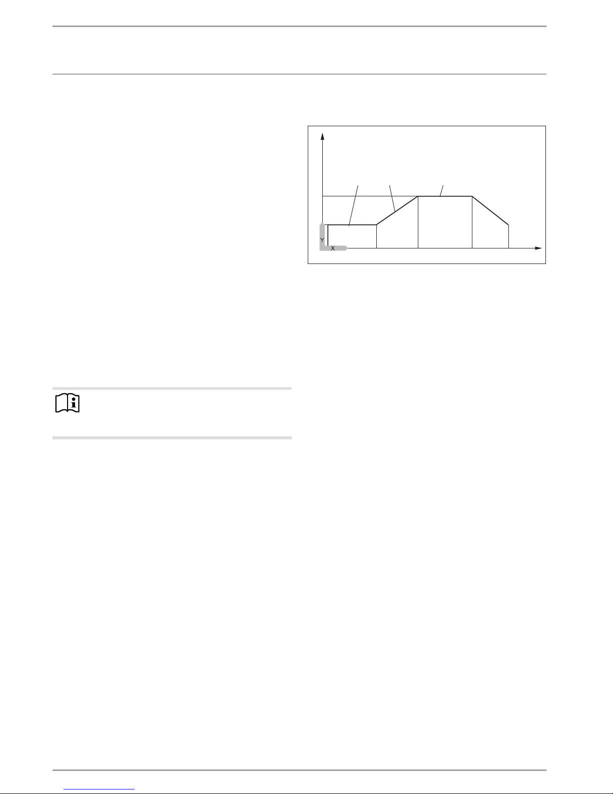
low end temperature.
The low end temperature (parameter LOW END TEMPERATURE)
is held for the selected time (parameter DURATION BASE TEMP).
After expiry of this period, the system heats to the maximum low
end temperature (parameter MAXIMUMTEMPERATURE) using
an increase K/day (parameter RISEPERDAY) and holds this maximum temperature for the selected time (parameter MAXTEM-
PERATURE DURATION). The system subsequently returns to the
low end temperature using the same steps as for heat-up.
1
7
4 5
3
2
84�03�01�0038
6
Y Temperature
X Time
1 Maximum temperature
2 Low end temperature
3 Low end temperature duration
4 Increase K/day
5 Max temperature duration
6 Start
7 End
If a heating buffer cylinder has been integrated into the system,
the temperature in the buffer cylinder is controlled solely via the
return sensor (fitted at the base of the buffer cylinder). If only the
direct heating circuit 1 is operational, the set values are reduced
by 5K to even out temperature differences in the buffer cylinder.
If 2 heating circuits are operational (second heating circuit is for
underfloor heating system), the mixer in heating circuit 2 regulates
down to the selected set values.
During the heat-up program the appliance often reaches maximum output. For this reason, energy consumption and noise levels
are comparatively high during screed drying.
After the heat-up process all modified parameters must be reset
to their standard values or system values.
Emergency operation is not possible while the heat-up program
is active.

OPERATION
Menu structure
www.stiebel-eltron.com WPF | WPF cool | 15
5.4 Settings menu
Here you can select all system-specific parameters for heating, cooling and DHW modes as well as general settings such as the time.
Note
Some menu options are protected by a code and can only be viewed and adjusted by a qualified contractor.
Level 2 Level 3 Level 4 Level 5
GENERAL TIME / DATE TIME
YEAR
MONTH
DAY
SETTING SUMMER TIME DAY BEGINNING
DAY ENDING
CONTRAST
BRIGHTNESS
TOUCH SENSITIVITY
TOUCH ACCELERATION
HEATING HEAT CIRCUIT 1 COMFORT TEMPERATURE
ECO TEMPERATURE
MINIMUM TEMPERATURE
HEATING CURVE RISE
HEATING CURVE VIEW
HEAT CIRCUIT 2 COMFORT TEMPERATURE
ECO TEMPERATURE
MINIMUM TEMPERATURE
MAXIMUM TEMPERATURE
MIXER DYNAMICS
HEATING CURVE RISE
HEATING CURVE VIEW
STANDARD SETTINGS BUFFER OPERAT
SUMMER MODE OUTSIDE TEMPERATURE
BUILDING HEAT BUFFER
MAXIMUM RETURN TEMP
MAXIMUM FLOW TEMP
FIXED VALUE OPERATION
HEATING CIRCUIT OPTIMAL
FROST PROTECT
REMOTE CONTROL FE7 HEATING CIRC PRESELECTION
ROOM INFLUENCE
ROOM CORRECTION
PUMPCYCLES ON / OFF
ELECTRIC REHEATING DUAL MODE TEMP HEATING
LOWER APP LIMIT HEATING
DHW DHW TEMPERATURES COMFORT TEMPERATURE
ECO TEMPERATURE
STANDARD SETTINGS DHW HYSTERESIS
DHW LEARNING FUNCTION
DHW CORRECTION
COMBI CYLINDER
PASTEURISATION ON / OFF

OPERATION
Menu structure
16 |WPF | WPF cool www.stiebel-eltron.com
ELECTRIC REHEATING DUAL MODE TEMP DHW
LOWER APP LIMIT DHW
COOLING COOLING ON / OFF
COOLING MODE PASSIVE COOLING / ACTIVE COOLING
ACTIVE COOLING AREA COOLING SET FLOW TEMPERATURE
FLOW TEMP HYSTERESIS
SET ROOM TEMPERATURE
DYNAMIC
FAN COOLING SET FLOW TEMPERATURE
FLOW TEMP HYSTERESIS
SET ROOM TEMPERATURE
DYNAMIC
PASSIV E COOLING AREA COOLING SET FLOW TEMPERATURE
FLOW TEMP HYSTERESIS
SET ROOM TEMPERATURE
FAN COOLING SET FLOW TEMPERATURE
FLOW TEMP HYSTERESIS
SET ROOM TEMPERATURE
5.4.1 General
Time / Date
Here you can set the time, year, month and day.
Setting Summer time
Here you can select summer time.
At the factory, summer time is set to begin on 25March and to
end on 25October.
Contrast
Here you can set the display contrast.
Brightness
Here you can set the display brightness.
Touch sensitivity and Touch acceleration
A code is required for this adjustment.
5.4.2 Heating
Heating circuit 1 and heating circuit 2
COMFORT TEMPERATURE and ECO TEMPERATURE
Here you can select the set room temperatures for Comfort mode
and ECO mode as well as the heating curve rise for heating circuit1
and heating circuit2.
Changing the set room temperature results in a parallel shift of
the heating curve.
The actual room temperature can also be scanned, as soon as the
FE7 remote control has been connected and allocated to heating
circuit 1.
The actual room temperature can also be scanned, as soon as the
FE7 or FEK remote control has been connected and allocated to
heating circuit2.
The display HEAT CIRCUIT2 only appears if the mixer flow sensor
for heating circuit2 has been connected.MINIMUM TEMPERATURE
The set MINIMUM TEMPERATURE is safeguarded by the heating
circuit controller and will never be undershot.
MAXIMUM MIXER TEMPERATURE
Setting range 20 °C to 90°C.
This setting limits the flow temperature of the mixer circuit. For
example, if a higher set flow temperature is calculated from the
mixer circuit data, the max. set mixer flow temperature will be
used to control and regulate to this value.
OPERATION
Menu structure
www.stiebel-eltron.com WPF | WPF cool | 17
MIXER DYNAMICS
Mixer runtime
Setting range 60 to 240
You can use this setting to adapt the mixer characteristics. The
setting 60 to 240 means 6 K to 24 K control deviation.
The scan rate is 10 s and the minimum on time for the mixer is
0.5 s. The mixer does not respond in the dead zone of ±1 K from
the set value.
Example for the setting 100 = 10 K
The control deviation (set mixer temperature – actual mixer temperature) is 5K. The mixer opens for 5 s, then pauses for 5 s and
starts again.
The control deviation (set mixer temperature – actual mixer temperature) is 7.5 K. The mixer opens for 7.5 s, then pauses for 2.5
s and starts again.
The smaller the control deviation, the shorter the mixer on time
and the longer the pauses.
A reduction of the MIXER DYNAMIC value with the control deviation unchanged increases the on duration and reduces pauses.
Example for setting 100 and a current control deviation of 5 K.
5 K of 10 K = 50% = on duration
Example: Control deviation
± 1 K
4
3
26�03�01�1067
1
2
1 Setting 100 = control deviation 10 K
2 Control deviation 5 K
3 Control deviation in K
4 On time in %
Heating curve rise
The menu item HEATING CURVE RISE enables you to adjust one
heating curve each for heating circuits1 and 2.
Note: Your contractor will have set a building and system-specific
optimum heating curve for every heating circuit. It relates to the
heat pump return temperature for heating circuit 1 and to the
mixer flow temperature for heating circuit 2.
When adjusting the heating curve on the heat pump manager, the
calculated set return or flow temperature, subject to the outside
temperature and the set room temperature, will be shown at the
top of the display.
As soon as you have preselected a temperature in menu SETTINGS
/ HEATING / STANDARD SETTING under parameter FIXED VALUE
OPERATION, heating curve 1 is hidden from view and the display
showsSETFIXED TEMPERATURE with the relevant temperature.
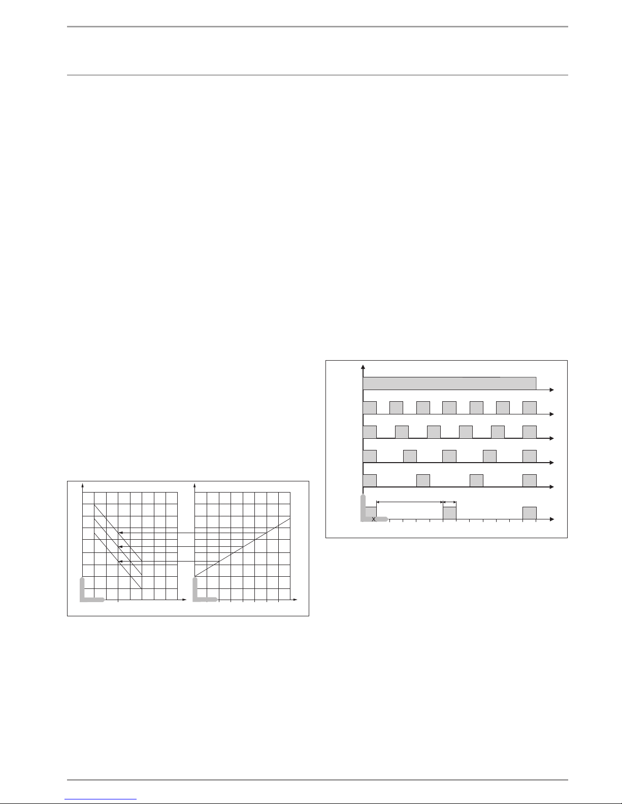
Heating curve
Adjustment of programmed changeover between Comfort and
ECO mode
The figure shows the diagram with the set heating curve relating
to a set room temperature for Comfort mode. The second, dashed
line in the display relates to a set room temperature for ECO mode.
60
40
20
0
1
2
20 15 10 5 0 -5 -10 -15 -20
26�03�01�1915
Y Return/flow temperature [°C]
X Outside temperature [°C]
1 Comfort mode
2 ECO mode
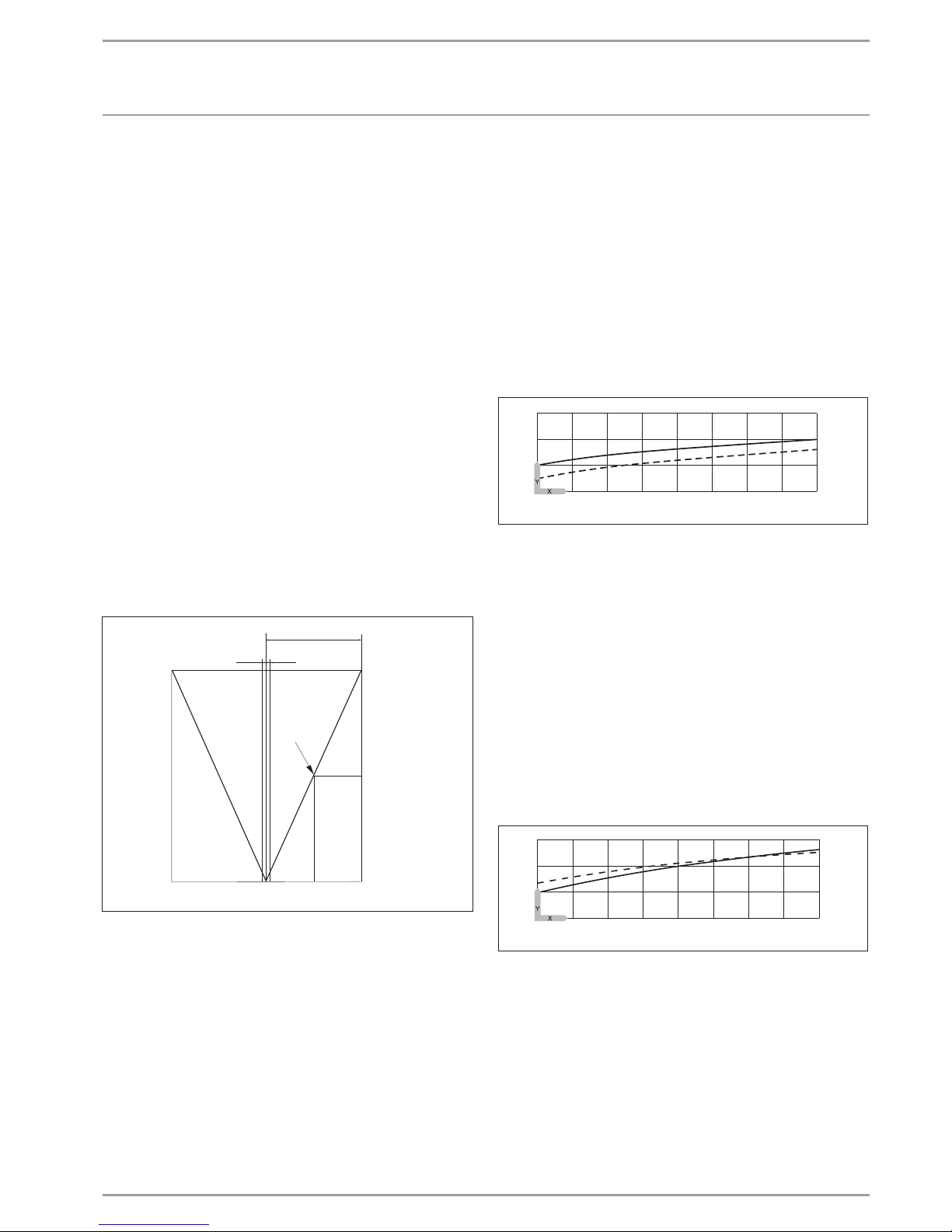
Adapting a heating curve
Example:
During spring and autumn, the temperature of a building's heating
system is too low at an outside temperature between 5 °C and
15°C, despite open radiator valves, but is OK at outside temperatures of ≤ 0°C. This problem can be remedied with a parallel shift
and a simultaneous reduction of the heating curve.
Prior to this adjustment, heating curve 1.0 was adjusted, relative
to a set room temperature of 20 °C. The dotted line indicates the
modified heating curve at 0.83 and a modified set room temperature of 23.2 °C.
60
40
20
0
20 15 10 5 0 -5 -10 -15 -20
26�03�01�1916+
Y Return/flow temperature [°C]
X Outside temperature [°C]

OPERATION
Menu structure
18 |WPF | WPF cool www.stiebel-eltron.com
Standard setting
Buffer operation
When using a buffer cylinder, set this parameter to ON.
Summer mode
The SUMMER MODE parameter can be used to define the point at
which the heating system is to switch to summer mode. Summer
mode can be switched ON or OFF. This function offers 2 adjustable
parameters.
- OUTSIDE TEMP parameter:
Available outside temperature 10 °C to 30 °C
- BUILDING HEAT BUFFER parameter
This parameter lets you choose whether an average outside temperature should be determined, according to the type of building.
You can select from 3 settings.
Setting "1": Minor insulation of the outside temperature (averaging
over a 24 h period), forexample timber construction with rapid
heat transfer.
Setting "2": Moderate insulation of the outside temperature (averaging over a 48 h period), for example solid construction with
thermal insulation and average heat transfer.
Setting "3": Heavy insulation (averaging over a 72 h period) of the
outside temperature. House with slow heat transfer.
Both heating circuits (if installed) enter summer mode if the determined outside temperature is ≥ than the selected outside temperature; reverse hysteresis –1 K.
With fixed-value control, summer mode is disabled for heating
circuit 1.
Maximum return temperature
Setting range 20 °C to 60 °C.
The heat pump is switched OFF immediately if the temperature
at the return sensor reaches this value during heating operation.
This safety function prevents the high pressure switch from responding. No fault message is issued when this value is reached.
During DHW operation the return temperature is not scanned.
Maximum flow temperature
Maximum heat pump flow temperature for central heating
Setting range 20 °C to 65 °C.
This setting limits the flow temperature of the heat pump and the
electric emergency/booster heater in heating mode.
Fixed value operation
The heat pump return is regulated to the set fixed value. The
switching time program will then be ignored. The various positions of the program selector will then only affect the mixer circuit
(if installed). The frost protection is activated and the compressor
is switched OFF when the program selector is set to standby and
a fixed temperature has been selected. Summer logic remains
disabled with fixed temperature control. This means that the heating circuit pump is not switched off for the direct heating circuit.
Heating circuit optimal
When an Uponor DEM WP module is connected, the heating curve
is dynamically optimised for the heat demand of individual rooms.
This involves modifying the preset heating curve by up to 50%
of its initial value.
The parameter HEATING CIRCUIT OPTIMAL is only displayed when
the parameter BUFFER OPERAT is set to OFF and neither a mixer
sensor nor an FE7 remote control are connected.
The parameter HEATING CIRCUIT OPTIMAL can be set to ON or OFF.
The default value is OFF.
This parameter may only be set to ON when an Uponor DEM WP
module is connected.
This function is only active in Comfort mode, ECO mode and Programmed operation.
Frost protection
To protect the heating system from frost, the heating circuit pumps
are started at the selected frost protection temperature; the reverse hysteresis is 1 K.
Remote control FE7
This menu item is only displayed when the FE7 remote control is
connected.
Heating circuit preselection
Remote control FE7 can be selected for both heating circuits.
This parameter lets you choose on which heating circuit the remote control is to act. Depending on the remote control preselection, you can query the actual room temperature under INFO/
SYSTEM/ROOM TEMPERATURE.
Room influence
Standard setting 5, adjustable from ---- via 0 to 20 Dashes (----)
in the display:
With the FE7 remote control connected, the room temperature
sensor only serves to record and display the actual room temperature; it has no influence on the actual control. Only in automatic
mode can the room temperature for heating circuit 1 or 2 be
adjusted by ± 5 °C. This set value adjustment applies to the then
current heating time, not to the setback time.
At the same time, setting "0 to 20" serves to control the room temperature-dependent night setback. This means that the heating
circuit pump is switched off at the point of changeover from the
heating into the setback phase. It remains off, until the actual room
temperature falls below the set room temperature. After this, the
system continues to regulate in weather-compensated mode.
If you want the room temperature to be taken into account, set
the room temperature sensor influence to > 0. The room sensor
influence has the same effect as the outside temperature sensor
has on the return temperature, except that the effect is 1 to 20
times greater, depending on the factor set.
OPERATION
Menu structure
www.stiebel-eltron.com WPF | WPF cool | 19
- Room temperature-dependent return/flow temperature
with weather compensation
With this type of control, a control cascade is formed from a return/flow temperature control that is subject to both weather and
room temperature. This means that the weather-compensated
return/flow temperature control sets a default return/flow temperature that is corrected by the overriding room temperature
control in accordance with the following formula:
∆ϕ
R
= (ϕ
RSOLL
− ϕ
RIST
) * S * K
Because a substantial proportion of the control is already handled by the weather-compensated control, the room temperature
sensor compensation factor K can be set lower than with pure
room temperature control (K=20). The figure indicates the control
method with the set factor K=10 (room influence) and a heating
curve S=1.2.
- Room temperature control with weather-compensation
This type of control offers two significant benefits:
Incorrectly set heating curves are corrected by the room sensor influence K; whilst the smaller factor K provides more stable control.
However, observe the following for all control units with room
temperature sensor influence:
- The room temperature sensor must capture the room temperature accurately.
- Open doors and windows greatly affect the control result.
- All radiator valves in the lead room must be fully open at all
times.
- The temperature inside the lead room affects the entire heating circuit.
If you want the room temperature to be taken into account, set
the room temperature sensor influence to > 0.
20
30
40
20
50
60
70
80
90
1917 18 21 22 23 24 25
0
10
0
20
-20
15
10
5
-5
-10
-15
Y
X 1
Y
X 2
1
1
1
2
3
4
5
26�03�01�1917
Y Flow temperature [°C]
X1 Room temperature [°C]
X2 Outside temperature [°C]
1 Room temperature sensor influence at K = 10 and S = 1.2
and control deviation +/- 2 K
2 Heating curve S = 1.2
3 Weather-compensated set flow temperature at ϕA =
- 10°C
4 Weather-compensated set flow temperature at ϕA = 0 °C
5 Weather-compensated set flow temperature at ϕA = +
10°C
Room correction
This parameter enables the calibration of the actual room temperature.
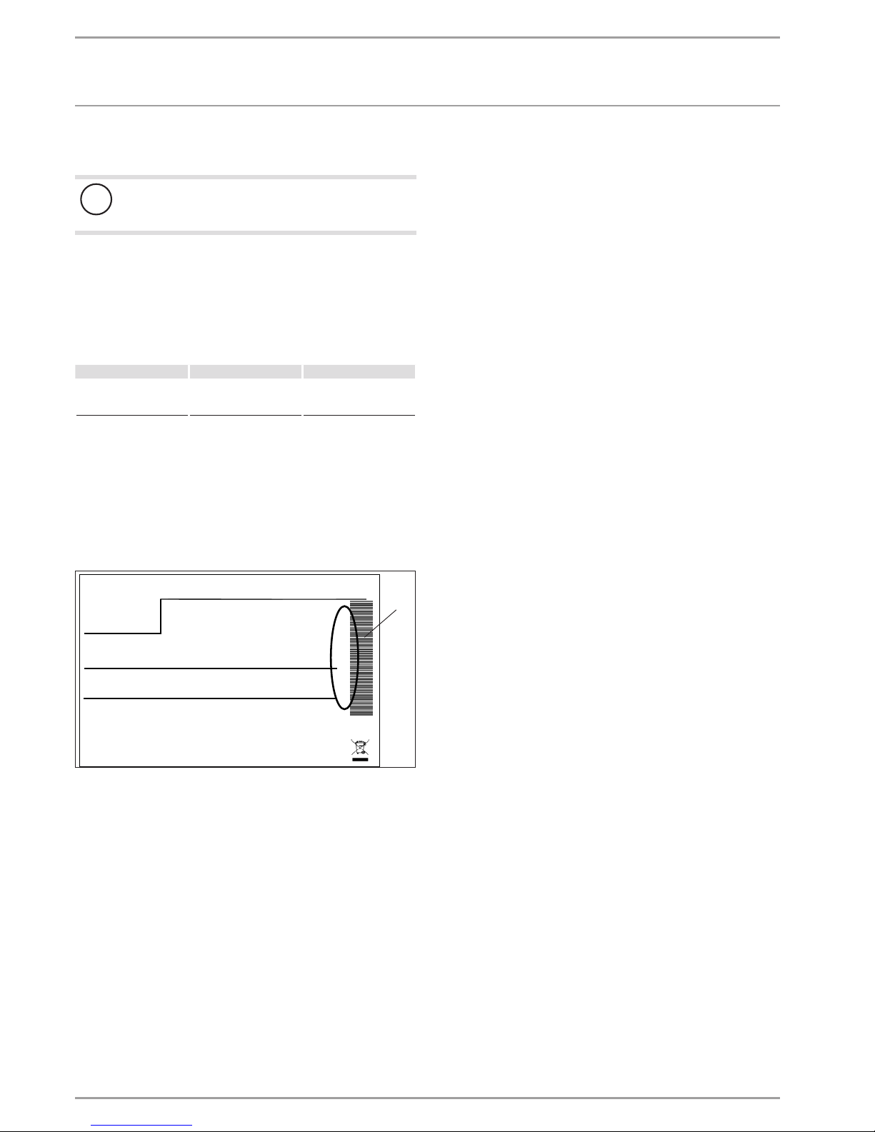
Pump cycles
- Heating circuit pump control
The PUMPCYCLES parameter only applies to the direct heating
circuit 1, i.e. for heating circuit pump 1.
This parameter can be set ON or OFF. In the OFF setting, the heating circuit pump will not cycle. It will operate constantly. It is only
switched off in summer mode.
As soon as this parameter is set to ON, the heating circuit pump
will be switched in line with a fixed temperature curve for the
outside temperature.
The heating circuit pump start pulse is always 5minutes.
The heating circuit pump for heating circuit 1 always starts with
each heat pump start. The pump runs on for 5 minutes after the
heat pump has been shut down. Now the start-up duration takes
effect, for example at an outside temperature of 5 °C, the pump
starts 3 times per hour for 5 minutes each time.
0 10 20 30 40 50 60
< -10
-10
-5
0
5
10
Y
2
1
84�03�01�0039
Y Outside temperature in °C
X Time in minutes
1 Pause
2 Pump run time
- Pump kick
To prevent the pumps seizing up, over summer for example, the
pumps are switched on for 10 seconds after every 24 hour period
of inactivity. This applies to all pumps.

OPERATION
Menu structure
20 |WPF | WPF cool www.stiebel-eltron.com
- Heating circuit pump control with connected remote
control FE7 / FEK
In conjunction with the FE7 or FEK remote control, in accordance
with the switching condition
ϕ
ACTUAL room
>ϕ
SET room
+ 1K
the respective heating circuit pump is switched off and the mixer
moves to CLOSE. This only applies if the room sensor influence is
set to K > 0. Reverse switching is subject to the following condition:
ϕ
ACTUAL room
>ϕ
SET room
The summer mode also becomes effective for the respective heating circuit when operating with a FE7 or FEK remote control.
Electric booster heater
Lower app limit HTG
Heat pump application limit
The heat pump is switched off if the outside temperature drops
below the selected lower application limit for heating.
The electric emergency/booster heater alone provides central
heating.
Dual mode temp HEATING
The dual mode temperature of the heat pump for heating operation
Below this outside temperature, the electric emergency/booster
heater is switched on for heating operation, subject to load.
5.4.3 DHW
DHW temperatures
COMFORT TEMPERATURE and ECO TEMPERATURE
Here you can select the set DHW temperatures for Comfort and
ECO mode.
Standard settings
DHW hysteresis
This determines the switching hysteresis for DHW operation.
- Starting DHW heating at the set DHW temperature minus the
hysteresis value.
DHW learning function
Setting OFF
When heating DHW, the system automatically adjusts itself to the
required DHW temperature (self-learning function).
The electric emergency/booster heater will be added as a booster
stage as soon as the heat pump is shut down in DHW mode via
the HP sensor or via the hot gas temperature limit (130 °C). If the
flow temperature of 70°C is achieved in this operating mode,
DHW heating will be terminated, and the set DHW temperature is
overwritten with the actual DHW temperature.
Setting ON
As soon as the heat pump is shut down in DHW mode via the HP
sensor or the hot gas temperature limit (130 °C), DHW heating is
terminated and the set DHW temperature will be overwritten with
the current actual DHW temperature. This operating mode saves
energy, as DHW is exclusively heated by heat pump.
DHW correction
The DHW temperature is measured in the bottom third of the
cylinder. The DHW outlet temperature is approx.3K higher than
the measured temperature. This deviation is corrected and can be
calibrated if necessary.
Combi cylinder
As soon as the parameter is set to ON, the heating circuit pumps
are switched off during DHW heating.
(Only in conjunction with the instantaneous water cylinder SBS)
Pasteurisation
The DHW cylinder is heated daily at 01:00 h to 60 °C if pasteurisation has been enabled. Pasteurisation only takes place when the
emergency/booster heater is connected.
Electric booster heater
Dual mode temp DHW
The dual mode temperature of the heat pump for DHW heating.
Below this outside temperature, the electric emergency/booster
heater is switched on for DHW heating, subject to load.
Lower app limit DHW
Lower application limit for the heat pump for DHW heating.
The heat pump is switched off at outside temperatures below the
selected lower DHW application limit.
The electric emergency/booster heater alone provides DHW heating.

OPERATION
Menu structure
www.stiebel-eltron.com WPF | WPF cool | 21
5.4.4 COOLING
!
Appliance and system damage
The WPF cool is only suitable for passive cooling. Active
cooling with the WPF cool will lead to appliance damage.
The WPF can be used for active and passive cooling. This,
however, is only possible in conjunction with a suitable
hydraulic circuit.
In the delivered condition, the COOLING parameter is set
to OFF.
!
Appliance and system damage
The WPF...S is not suitable for cooling.
Cooling
On / OFF
Cooling mode
Passive cooling / active cooling
Active cooling
Area cooling
- Flow temperature
- Flow temp. hysteresis
- Set room temperature
- Dynamic
Fan cooling
- Flow temperature
- Flow temp. hysteresis
- Set room temperature
- Dynamic
Passive cooling
Area cooling
- Flow temperature
- Flow temp. hysteresis
- Set room temperature
Fan cooling
- Flow temperature
- Flow temp. hysteresis
- Set room temperature
Note
The COOLING parameter will only be shown if an FEK or
FE7 remote control is connected. Cooling mode is only
possible in summer mode.
The WPF with a suitable circuit cools in 2 stages:
Stage 1 (source pump)
Heat is extracted from the heating circuit and is passed to the
heat source system.
Stage 2 (source pump + compressor)
In addition, the refrigerant circuit extracts heat from the heating
circuit and transfers it to the heat source system.
DHW heating
DHW heating always has priority. As long as the actual temperature has not dropped below the set flow or room temperature, active cooling continues even during DHW heating, and any extracted
heat is transferred to the DHW. If there is no cooling demand, DHW
is conventionally heated via the heat source system.
Cooling mode with the FE 7
The FE7 is not equipped with dew point monitoring. It can therefore only be used in conjunction with fan convectors with condensate drain. Set COOLING MODE parameter to FAN.
Cooling mode with the FEK
The FEK remote control is equipped with dew point monitoring,
and can therefore be used with area heating systems (e.g. underfloor/wall heating systems, etc.). Set parameter COOLING to
AREA COOLING. The set flow temperature is compared with the
captured dew point temperature, so the actual temperature never
drops below the dew point. When using fan convectors with the
FEK remote control, set the COOLING parameter to FAN COOLING.
The following settings for the FE 7 and the FEK can be selected for
Cooling mode in parameterCOOLING:
- Room temperature
Cooling mode starts when the selected room temperature is
exceeded (output COOLING=230 V).
Cooling mode is stopped, if the actual room temperature
drops 2K below its set temperature. (output COOLING=0 V)
- Flow temperature and hysteresis
Cooling mode is regulated via the selected flow temperature.
The brine pump starts at:
[Flow temperature + hysteresis]
Brine pump off when the actual temperature drops below the
flow temperature.
The [flow temperature+hysteresis] should be at least 3 K <
room temperature. Lower flow temperatures cause a more
rapid cooling of the room.
As soon as, with setting AREA COOLING, the determined dew
point temperature is + 2 K higher than the selected flow temperature, that temperature will be overridden with the dew
point temperature and acts as control variable. The brine
pump starts at [entered or newly determined flow temp. +
hysteresis].
The source pump stops and Cooling mode terminates, if the
actual flow temperature lies below the entered or newly
determined flow temperature. The cooling signal remains
active.
- Dynamic
The Dynamic can be adjusted from 1 to 10. It describes the
delay and changeover between passive cooling and active
cooling, whereby active cooling is started sooner, the smaller
the value.
OPERATION
Maintenance and care
22 |WPF | WPF cool www.stiebel-eltron.com
6. Maintenance and care
!
Appliance and system damage
Maintenance work, such as checking the electrical safety,
must only be carried out by a qualified contractor.
A damp cloth is sufficient for cleaning all plastic and sheet metal
parts. Never use abrasive or corrosive cleaning agents.
We recommend an annual inspection (to establish the current condition of the system), and maintenance by a qualified contractor if
required (to return the system to its original condition).
7. Troubleshooting
Fault Cause Remedy
There is no hot water or
the heating system stays
cold.
The fuse/MCB has blown/
responded.
Check the fuse/MCB in
your fuse box/distribution panel.
7.1 Other problems
If you cannot remedy the fault, notify your qualified contractor.
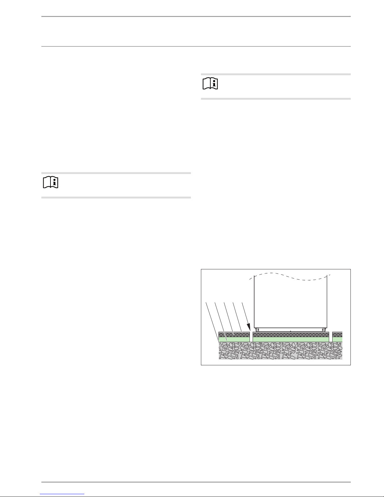
To facilitate and speed up your enquiry, please provide the serial
number from the type plate. The type plate is located at the front
top, on the right or left hand side of the casing.
Sample type plate
Montageanweisung beachten! Dichtheit geprüft!
Made in Germany
*xxxxxxxxxxxxxxxxxx*
1
26�03�01�1570
1 Number on the type plate
www.stiebel-eltron.com WPF | WPF cool | 23
INSTALLATION
Safety
INSTALLATION
8. Safety
Only a qualified contractor should carry out installation, commissioning, maintenance and repair of the appliance.
8.1 General safety instructions
We guarantee trouble-free function and operational reliability only
if original accessories and spare parts intended for the appliance
are used.
8.2 Instructions, standards and regulations
Note
Observe all applicable national and regional regulations
and instructions.
9. Appliance description
9.1 Mode of operation
The heat exchanger on the heat source side (evaporator) extracts
natural heat from the heat source. Any energy extracted is transferred, together with the energy drawn by the compressor drive,
to the heating water by a heat exchanger on the heating water
side (condenser). Subject to the heat load, the heating water is
heated up to + 65°C.
The electric emergency/booster heater starts if the high pressure
sensor or the hot gas limiter responds during DHW heating. In
addition it covers any residual heat demand, if the heating system
demand exceeds the heat pump output.
9.2 Special features of the WPF...cool
For cooling, the brine is pumped, via a further three-way valve
through a second heat exchanger, where the energy is extracted
from the heating water.
9.3 Standard delivery
The following are delivered with the appliance:
- 1 outside temperature sensor AFS2
- 1 immersion sensor TF6
- 6 push-fit connectors 28) mm
9.4 Accessories
- Brine charging unit WPSF
- Water softener fitting HZEA
- Filter assembly 22 mm (FS-WP 22)
- Filter assembly 28 mm (FS-WP 28)
- Remote control FE 7
- Remote control FEK
10. Preparations
Note
The appliance is designed for internal installation, except
in wet areas.
Never install the appliance directly below or next to
bedrooms.
Protect pipe transitions through walls and ceilings with an-
ti-vibration insulation.
The room in which the appliance is to be installed must meet the
following conditions:
- No risk from frost.
- The room must not be subject to a risk of explosions arising
from dust, gases or vapours.
- When installing the appliance in a boiler room together with
other heating equipment, ensure that the operation of other
heating equipment will not be impaired.
- The volume of the installation room should be at least
13.8m³.
- Load-bearing floor (for the weight of the internal unit, see
chapter “Specification / Data table”).
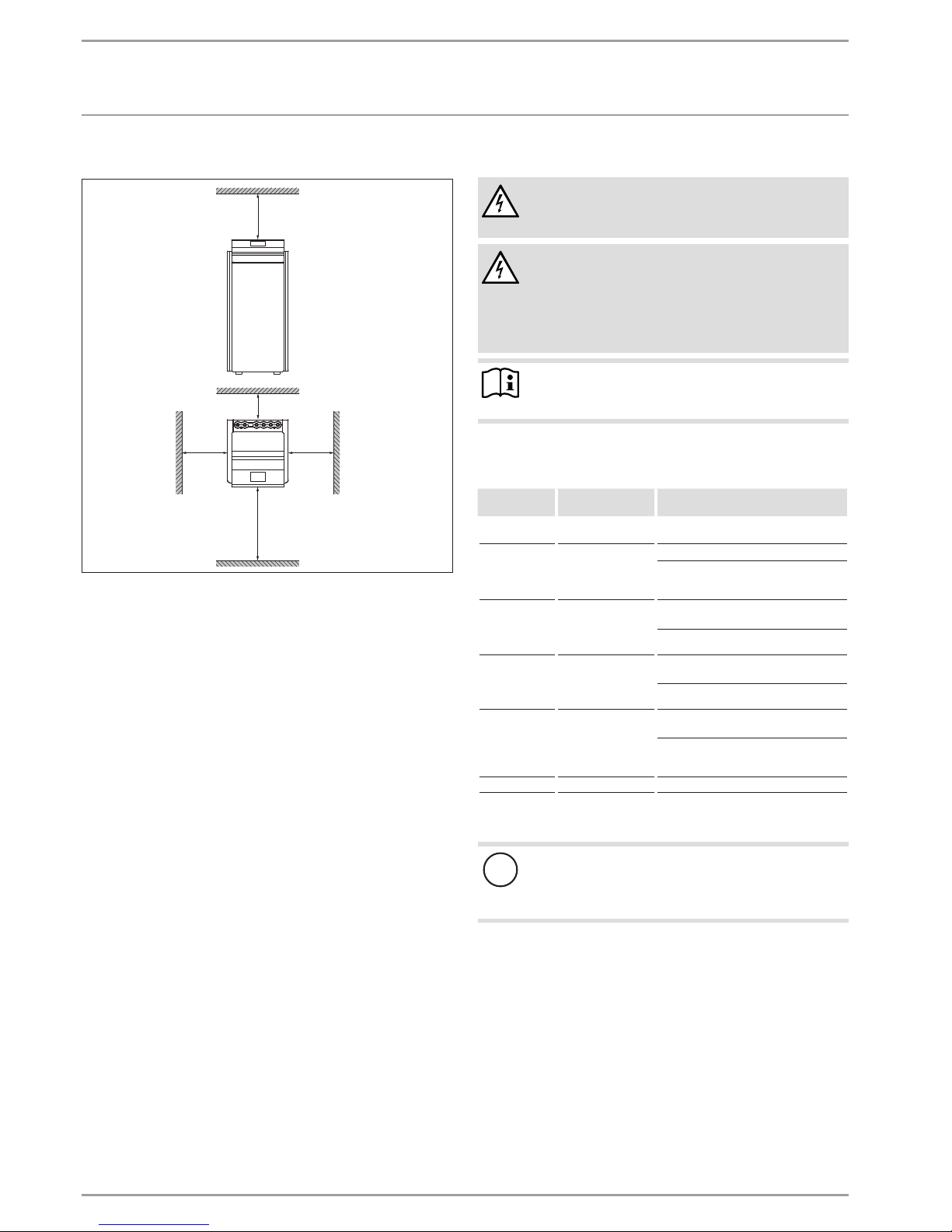
For installation on floating screeds, make provisions for quiet
heat pump operation.
Isolate the mounting surface around the heat pump by re-
cesses. After completing the installation, seal these recesses
with a water-impervious and sound insulating material, such
as silicone for example.
1 2 3 54
26�03�01�1466
1 Concrete base
2 Impact sound insulation
3 Floating screed
4 Floor covering
5 Recess
24 |WPF | WPF cool www.stiebel-eltron.com
INSTALLATION
Preparations
10.4.1 Minimum clearances
≥500
≥50
≥500
≥500
≥1000
D0000034469
Maintain the minimum clearances to ensure trouble-free op-
eration of the appliance and facilitate maintenance work.
10.1 Electrical installation
DANGER Electrocution
Carry out all electrical connection and installation work
in accordance with national and regional regulations.
DANGER Electrocution
Only use a permanent connection to the power supply.
Ensure that the appliance can be separated from the
power supply by an isolator that disconnects all poles
with at least 3mm contact separation. This requirement
can be met with contactors, circuit breakers, fuses, etc.
Note
The specified voltage must match the mains voltage. Observe the type plate.
Install cables with the following cross-sections in accordance with
the respective fuse rating:
Fuse/MCB
rating
Assignment Cable cross-section
C 16 A Compressor
(three phase)
2.5 mm²
B 16 A
Electric emergency/
booster heater (BH)
(three phase)
2.5 mm²
1.5 mm² with only two live cores and
routing on a wall or in an electrical conduit on a wall.
C 16 A
Compressor
WPF 05 S / 07 S
(single phase)
1.5 mm² for open routing. Note the type
of routing!
2.5 mm² for routing through a
wall. Note the type of routing!
C 25 A
Compressor
WPF 10 S / 13 S
(single phase)
4.0 mm² for open routing. Note the type
of routing!
6.0 mm² for routing through a
wall. Note the type of routing!
B 16 A
Electric emergency/
booster heater (BH)
(single phase)
2.5 mm² for routing through a
wall. Note the type of routing!
1.5 mm² when routing a multi core line
on a wall or in an electrical conduit on
a wall.
B 16 A Control unit 1.5 mm²
The electrical data is provided in the chapter "Specification / Data
table".
!
Material losses
Provide separate fuses/MCBs for the two power circuits
of the compressor and the electricemergency/booster
heater.
 Loading...