

STIEBEL ELTRON SBP 200 E, SBP 700 E, SPB 400 E, SBP 700 E SOL Operating And Installation Instructions
268941
SBP 200 E, SPB 400 E, SBP 700 E, SBP 700 E SOL with WPKI 5
Operating and installation instructions
SBP 200 E / WPKI 5
1. Operating instructions 3
1.1 Cylinder description 3
1.2 Special accessories 3
1.3 Essential special accessories
1.4 Operating and installation instructions 3
2. Installation instructions 3
2.1 Cylinder construction 3
2.2 Regulations 3
2.3 Place of installation 3
2.4 Cylinder casing assembly/removal 3
2.5 Immersion heater installation 5
2.6 WPKl 3 installation 5
2.7 Commissioning 5
2.8 Maintenance 5
26_03_01_0222
2
7
6
5
SBP 200 E (SBP 400)
18 17
1
2
9
8
3
4
10
Dimensions in mm
1
2
10
8
14
10
11
11
7
6
5
4
Dimensions in mm
SBP 700 E / SBP 700 E SOL
10
9
13
12
16
15
15
A
B
C
D
C26_03_01_0225
26_03_01_0227
230
140
800
1535
140
295
Ø 630
(1710)
(925)
(250)
(320)
(Ø 750)
C26_03_01_0229
26_03_01_0225
C26_03_01_0225
3
2. Installation instructions for contractors
1. Instructions for users and contractors
SBP 200 E Part no: 18 54 58
SBP 700 E Part no: 18 54 59
SBP 400 E Part no: 22 08 24
SBP 700 E SOL Part no: 18 54 60
1.1 Cylinder description
The sealed freestanding cylinder (with a volume of 200 or 700 litres) acts as buffer cylinder
for heat pumps.
A buffer cylinder is recommended to ensure
trouble-free heat pump operation. It acts as
a bridge during electricity supply shutdown
periods and as separator between the volume
flow in the heat pump and that in heating
circuits.
Features of the SBP 700 E SOL
The cylinder SBP 700 E SOL is also fitted with
a heat exchanger for boosting the DHW with
solar energy.
1.2 Special accessories
WPKI 5 Part no: 22 08 30
The compact installation heat pump set
WPKl 3 is designed especially for use with
buffer cylinders SBP 200 E, SBP 400 and
SBP 700 E (SOL). Clear and simple connection
of buffer cylinder SBP to heat pumps WPL.
WPKI 6 Part no: 22 08 31
The compact heat pump set WPKl 4 is desi
gned especially for use with buffer cylinders
SBP 200 E and SBP 700 E (SOL). Clear and sim
ple connection of buffer cylinder SBP to heat
pumps WPF.
Inserts Part no: 00 37 11
For close fitting pipe connection of the buffer
cylinder without heat pump compact installati
on WPKl 3. This set comprises 4 inserts,
4 gaskets and 4 union nuts G 2”.
Thermally insulated pressure hoses
G 1¼” x 1 m (DN 25) Part no: 07 44 15
G 1¼” x 2 m (DN 25) Part no: 07 44 16
G 1¼” x 5 m (DN 25) Part no: 07 44 17
G 1¼” x 1 m (DN 32) Part no: 07 44 14
G 1¼” x 2 m (DN 32) Part no: 18 20 19
G 1¼” x 5 m (DN 32) Part no: 18 20 20
1.3 Essential special
accessories
UP 25-60-180 Part no: 07 43 25
UP 25-80-180 Part no: 07 43 16
For further accessories, see the design docu
-
mentation.
1.4 Operating and installation instructions
Observe the operating and installation instructions of the components for each relevant
system.
Keep these operating instructions
in a safe place and pass them on to
any new user, should the equipment change
hands. Let your contractor check their content in conjunction before commencing any
maintenance or repair work
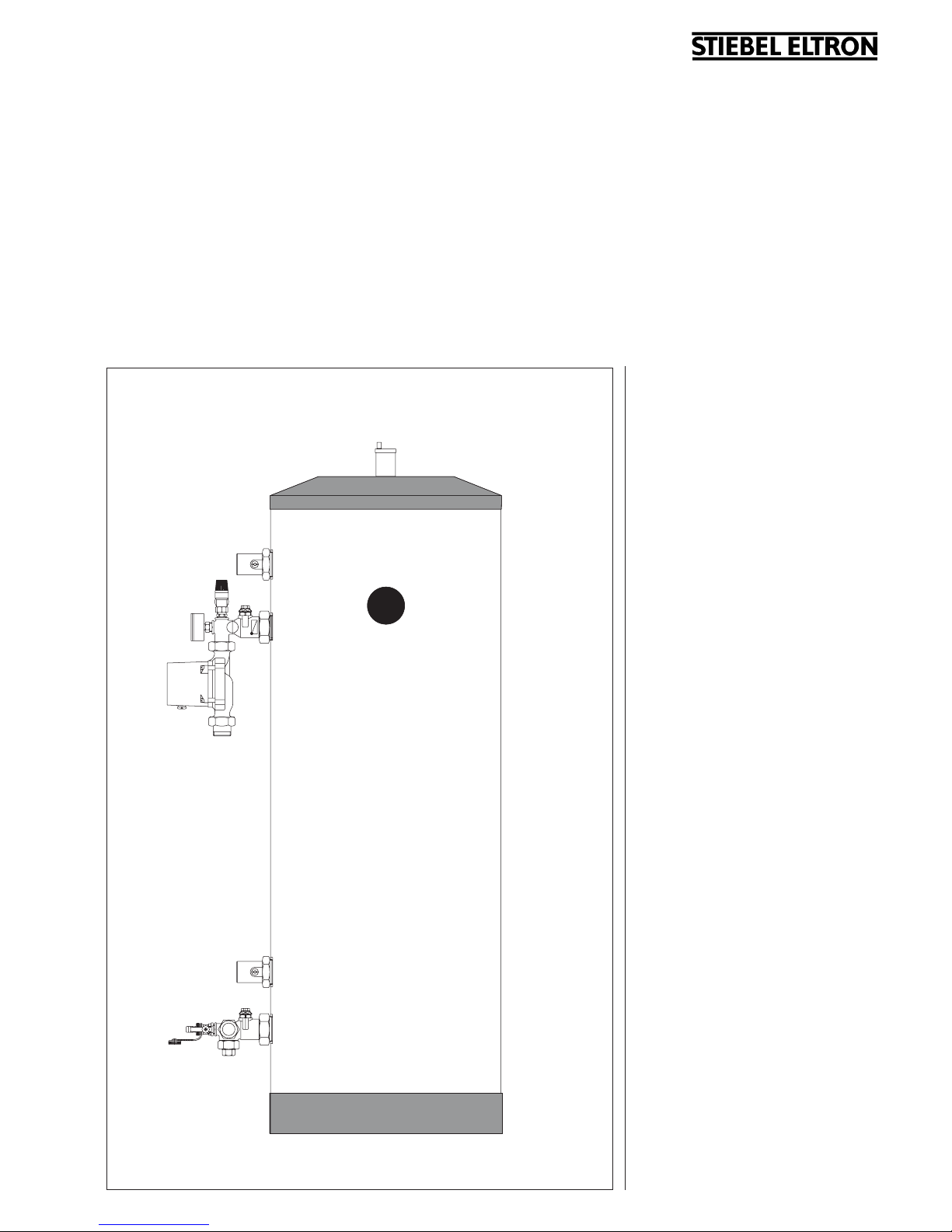
To prevent damage and contaminati-
on, we recommend that the cylinder
casing is removed for transportation and
installation (see 2.3).
Do not use a barrel clamp!
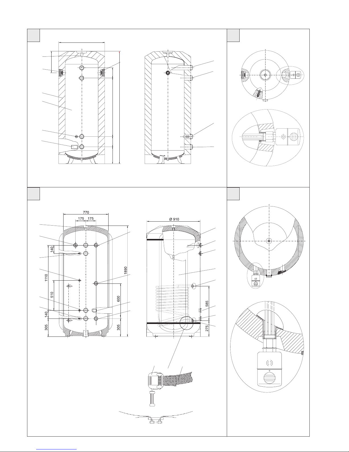
2.1 Cylinder construction
(A, B, E)
1 Ventilation connectors R ¾” and
combined
temperature and pressure relief valve
2 PUR foam thermal insulation
3 Steel container
4 G 2” flow connector, heat pump compact
installation
5 G 2” heating flow connector
6 G 2” heating return connector
7 G 2” return connector, heat pump compact
installation
8 G ½” connector with protective pipe for HP
return temperature sensor
9 Type plate (on the protective cover)
10 G 1½” connectors, for electric immersion
heater
11 G ½” connector, sealed with plug
12 G 1” flow connector, HE solar
(only SBP 700 E SOL)
13 G 1” return connector, HE solar
(only SBP 700 E SOL)
14 G ½” connector with protective sleeve for
temperature sensor (only SBP 700 E SOL)
15 G 1½” connector for additional heat source
16 PUR foam body, thermal insulation segment
17 Retaining strap
18 Buckle
19 Plastic casing
20 Plastic lid
21 Plastic plinth cover
2.2 Regulations
• Installation and commissioning, as well
as the maintenance of this equipment,
must only be carried out by an authori-
sed qualified contractor in accordance
with these instructions.
• Optimum function and safe operation
can only be assured when using original,
specialised accessories and spare parts
intended for this equipment.
2.3 Place of installation
The installation location should be safe from
frost. If the system is not in use at times when
frost is likely, drain the cylinder and the whole
system connected to it, to prevent damage.
Ensure that the floor at the installation loca
tion is a load bearing surface, which must be
level and even.
Secure the cylinder feet firmly to the floor to
prevent tipping.
Minimum ceiling height:
1.80 m for SBP 200 E,
2.00 m for SBP 400 E and
2.10 m for SBP 700 E.
2.4 Cylinder casing
assembly / removal
The cylinder casing is fitted in the delivered
condition. It can be removed if necessary.
Removal (E):
1. Removing the plastic lid (20)
2. Removing the plastic plinth cover (21)
3. Removing the plastic casing (19)
Installation in reverse order.
Fit the cylinder casing before installation work begins on the immersion
heater.
Features of the SBP 700 E and
the SPB 700 E SOL (B)
The two polyurethane foam segments, attached to both sides of the cylinder, can be
removed to ensure safe transportation of the
cylinder through narrow passages and door-
SBP 200 E SBP 400 E SBP 700 E SBP 700 E SOL
Weight: empty:
full
kgkg56
256
82
482
145
845
176
876
Height of unit when tilted:
mm 1650 1800 2000 2000
Permissible operating pressure MPa (bar) 0,3 (3) 0,3 (3) 0,3 (3) 0,3 (3)
 Loading...