

Page 1
Simply the Best
Installation
Operation
Functions and options
Troubleshooting
SOM 9s
Thank you for buying this product.
Read this manual carefully to get the best performance from this unit.
*49012850*
49012850
Please keep this manual carefully.
en-US/CA
Manual
SOM 9s
Page 2
SOM 9s
Contents
1 Overview ............................................................. 3
2 Installation .......................................................... 4
2.1 Mounting ....................................................................4
2.2 Electrical connection ...............................................4
2.3 Data communication / Bus ....................................6
2.4 SD card slot ..............................................................6
2.5 Overview of the systems .......................................7
2.6 System layouts ..........................................................9
3 Operation and function ................................... 69
3.1 Buttons .................................................................... 69
3.2 Selecting menu points and adjusting values ... 69
3.3 Menu structure ...................................................... 69
3.4 Indications and system monitoring display......70
3.5 Further indications ............................................... 71
4 Status menu ..................................................... 72
5 Initial commissioning ....................................... 73
General
Safety advice:
Please read the following information carefully before
installing and operating the controller. In this way damage
to the solar system caused by wrong installation will be
avoided. Please make sure that the mounting is adapted to
the characteristics of the building, that the local regulations
are respected and is conform with the technical rules.
Please pay attention to the following safety advice in order
to avoid danger and damage to people and property.
6 Functions and options ..................................... 75
6.1 Status level .............................................................. 75
6.2 Adjustment channels ............................................ 78
6.3 Overview of options and their parameters .... 94
7 User code and short menu -
Adjustment values ............................................ 96
8 Messages ........................................................... 97
9 Troubleshooting ............................................... 98
9.1 Miscellaneous ......................................................... 99
10 Accessories .................................................... 101
10.1 Sensors and measuring instruments ............... 101
10.2 Interface adapters ............................................... 101
10.3 Visualization modules ........................................102
11 Index ................................................................ 103
Subject to technical change. Errors excepted.
Instructions:
Attention should be paid to
• Valid national and local standards and regulations
• Respective valid standards and directives
Equipment to be installed and used in accordance with
the rules of the National Electrical Code (NEC) or with
Canadian Electrical Code (CEC), Part I.
These instructions are exclusively addressed to authorized
skilled personnel.
• Only qualied electricians should carry out installation and
maintenance work.
• Initial installation should be carried out by qualied personnel
Description of symbols
WARNING! Warnings are indicated with a
warning triangle!
They contain information on how
to avoid the danger described.
Signal words describe the danger that may occur, when it
is not avoided.
WARNING means that injury, possibly life-threatening
injury, can occur.
ATTE NTIO N means that damage to the appliance can
occur.
Note
Notes are indicated with an information
symbol.
Î Arrows indicate instruction steps that should be car-
ried out.
| 2
Information about the product
Proper usage
The solar controller is designed for use in solar thermal
and heating systems in compliance with the technical data
specied in these instructions.
Improper use excludes all liability claims.
Note
Strong electromagnetic elds can impair the
function of the controller.
Î Make sure the controller as well as the
system are not exposed to strong electro-
magnetic elds.
© Stiebel 11091_SOM_9s.monus.indd
Page 3
SOM 9s
1 Overview
• Extralargegraphicdisplay
• 4relayoutputs
• 7sensorinputs,
2 of them for Grundfos Direct Sensors™
• 2PWMoutputsforspeedcontrolofhighefciencypumps
• DataloggingontoSDcard
• Drainbackoption
• Time-controlledthermostatfunction
• VBus
®
• Energy-savingswitch-modepowersupply
Included:
1 x SOM 9s
1 x accessory bag
3 x screw and wall plug
8 x strain relief and screw
Additionally included in the full kit:
2 x FKP6 sensor
2 x FRP6 sensor
Note:
For more information about accessories, see
p. 101.
Note:
The SD card is not included with the controller
Technical data
Housing:
plastic, PC-ABS and PMMA
Protection type: IP 20 / EN 60 529
Protection class: I
Ambient temp.: 32 ... 104 °F
Dimensions: 204 x 170 x 47 mm
Mounting: wall mounting, also suitable for mounting into
patch panels
Display: System-Monitoring-Display for system visuali-
zation, 16-segment display, 7-segment display, 8 symbols,
control lamp (directional pad) and background illumination
Operation: 7 push buttons at the front of the housing
Functions: System controller for solar and heating sys-
tems. Functions such as: DT control, pump speed control,
Inputs:
5 inputs for Pt1000 temperature sensors, inputs for 1
Grundfos Direct Sensor™ VFS and 1 Grundfos Direct
Sensor™ RPS, 1 Impulse input V40
Outputs:
3 semiconductor relays, 1 standard relay, 2 PWM outputs
Interfaces: VBus
®
, SD card slot
Power supply:
100 ... 240 V~, 50 ... 60 Hz
Switching capacity per relay:
1 (1) A 100 ... 240 V~ (semiconductor relay)
2 (1) A 100 ... 240 V~(standard relay)
Total switching capacity: 4 A
Standby power consumption: < 1W
Mode of operation: type 1.Y
energy metering, operating hours counter for the solar
pump, evacuated tube collector function, thermostat function, vertical tank loading, priority logic, drainback option,
booster function, heat dump function, thermal disinfection
function, PWM pump control.
© Stiebel 11091_SOM_9s.monus.indd
3 |
Page 4
SOM 9s
2 Installation
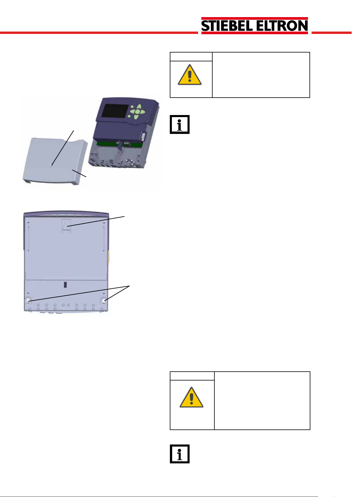
2.1 Mounting
screw
cover
upper fastening
point
lower fastening point
WARNING! Electric shock!
Upon opening the housing, live parts
are exposed.
Î Always disconnect the control-
ler from power supply before
opening the housing!
Note
Strong electromagnetic fields can impair the
function of the controller.
Î Make sure the controller as well as the
system are not exposed to strong electro-
magnetic elds.
The unit must only be located in dry interior rooms.
The controller must additionally be supplied from a double
pole switch with contact gap of at least 3 mm.
Please pay attention to separate routing of sensor cables
and power supply cables.
In order to mount the device to the wall, carry out the
following steps:
Î Unscrew the cross-head screw from the cover and re-
move it along with the cover from the housing
Î Mark the upper fastening point on the wall. Drill and
fasten the enclosed wall plug and screw leaving the head
protruding
Î Hang the housing from the upper fastening point and
mark the lower fastening points (centres 150 mm)
Î Insert lower wall plugs
Î Fasten the housing to the wall with the lower fastening
screws and tighten
Î Carry out the electrical wiring in accordance with the
terminal allocation, see chap. 2.2
Î Put the cover on the housing
Î Attach with the fastening screw
2.2 Electrical connection
| 4
ATTENTION! ESD damage!
Electrostatic discharge can lead to damage to electronic components!
Î Take care to discharge proper-
ly before touching the inside
ofthedevice!Todoso,touch
a grounded surface such as a
radiator or tap!
Note:
The pump speed must be set to 100 % when
auxiliary relays or valves are connected.
© Stiebel 11091_SOM_9s.monus.indd
Page 5

SOM 9s
VFS
RPS
Te mp. Sensor
Pt1000
S3
S1
S2
S4
S5
GND
1
PWM
2
PWM
T4A
100 ... 240V~
R1-R3
1 (1)A (100 ... 240)V~
2 (1)A (100 ... 240)V~
R4
L
L'
R4
V40
VBus
R3
R1
R2
N
WARNING! Electric shock!
Upon opening the housing, live parts
are exposed.
Î Always disconnect the control-
ler from power supply before
opening the housing!
The controller is supplied with power via a power supply
cable. The power supply of the device must be 100 ... 240V~
(50 ... 60 Hz).
The controller is equipped with 4 relays in total to which
loads such as a pump, a valve, etc. can be connected:
• Relays R1 ... R3 are semiconductor relays, designed for
pump speed control
Conductor R1... R3
Note:
Connecting the device to the power supply must
always be the last step of the installation!
Neutral conductor N
Ground terminal
• Relay 4 is a standard relay
Conductor R4
Neutral conductor N
Ground terminal
Depending on the product version, power supply cable and
sensor cables are already connected to the device. If that is
not the case, please proceed as follows:
Connect the temperature sensors (S1 to S5) to the
corresponding terminals with either polarity:
S1 = sensor 1 (collector sensor )
S2 = sensor 2 (e. g. tank sensor bottom)
S3 = sensor 3 (e. g. tank sensor top)
S4 = sensor 4 (e. g. tank sensor tank 2)
Note:
The connection depends on the system selected,
see chap. 2.6. “System layouts”
S5 = sensor 5 (e. g. collector sensor collector 2)
Connect the Grundfos sensors to the VFS and RPS inputs.
A V40owmeter can be connected to the terminals V40
and GND (either polarity).
The terminals marked “PWM” are control outputs for a
WARNING! Electric shock!
L' is a fused contact permanently
carrying voltage
Î Always disconnect the control-
ler from power supply before
opening the housing!
high-efciency pump (PWM1 is allocated to R1 and PWM2
is allocated to R2).
The power supply connection is at the terminals:
Neutral conductor N
Conductor L
Conductor L' (L' is not connected with the power supply
cable. L' is a fused contact permanently carrying voltage)
Note:
Ground terminal
For more details about the initial commissioning
procedure, see chap. 5, page 73.
© Stiebel 11091_SOM_9s.monus.indd
5 |
Page 6

SOM 9s
2.3 Datacommunication/Bus
The controller is equipped with the VBus® for data transfer
with and energy supply to external modules. The connection is carried out at the two terminals marked “VBus” and
GND (any polarity). One or more VBus® modules can be
connected via this data bus, such as:
• GA3 Large display module / Smart Display SD3
• AM1 Alarm module
• DL2 Datalogger
Furthermore, the controller can be connected to a PC
via the VBus
included with the SOM 9s). With the ServiceCenter Software (RSC), measured values can be read, processed and
visualized. The software allows easier function control and
adjustment of the system.
®
/USB or VBus®/LAN interface adapter (not
Note:
For more information about accessories, see
p. 101.
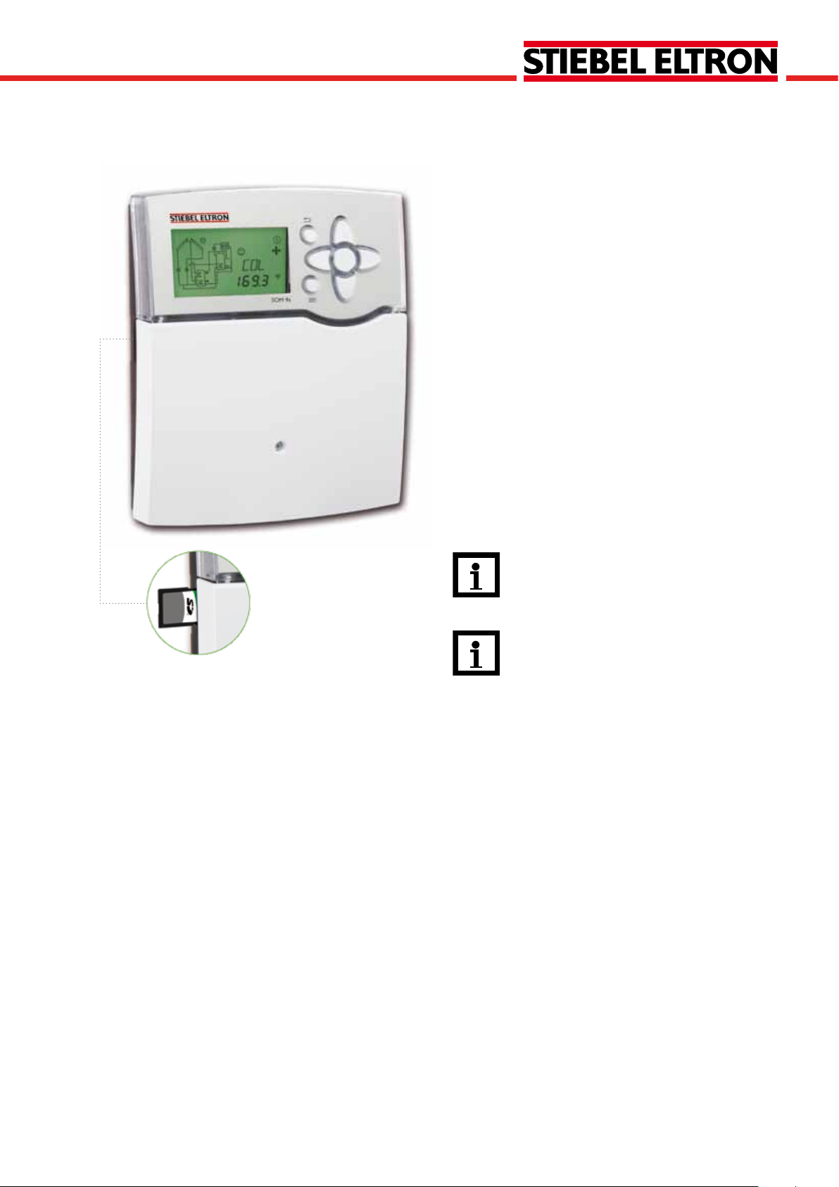
2.4 SD card slot
The controller is equipped with an SD card slot for storing
system data onto an SD card. The values can be opened and
visualized, e. g. in a spreadsheet programme.
Note:
Do not use an SD-HC card!
A standard SD card is not included with the SOM 9s.
For more information about using an SD card, see chap. 6.2
(page 93) “SD card“.
| 6
© Stiebel 11091_SOM_9s.monus.indd
Page 7
SOM 9s
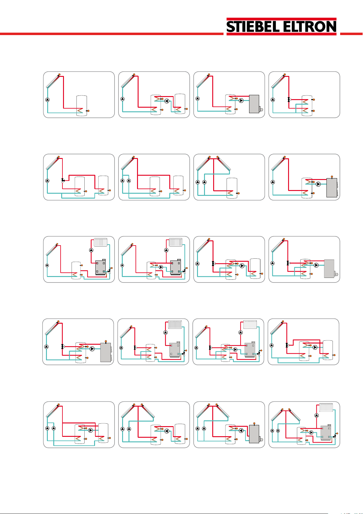
2.5 Overview of the systems
1 2 3 4
Standard solar system with 1
tank (page 9)
Solar system with 2 tanks and
heat exchange (page 11)
Solar system with 1 tank and
backup heating (page 13)
Solar system with 1 tank and
3-port valve for vertical tank
loading (page 15)
5 6 7 8
2-tank system with valve
logic, 1 pump, 3 sensors and
3-port valve (page 17)
2-tank solar system with
pump logic (page 19)
Solar system with east-/west
collectors (page 21)
Solar system with 1 tank and
backup heating with solid fuel
boiler (page23)
9 10 11 12
Solar system with 1 tank and
heating circuit return preheating (page 25
Solar system with 1 tank, heating circuit return preheating and thermostatic backup
heating (page 27)
Solar system with vertical
tank loading and heat exchange control (page 29)
Solar system with vertical
tank loading and thermostatic
backup heating (page 31)
13 14 15 16
Solar system with vertical
tank loading and backup
heating with solid fuel boiler
(page 33)
Solar system with vertical
tank loading and return preheating (page 35)
Solar system with vertical
tank loading and backup
heating with heating backup
(page 37)
2-tank solar system with
valve logic and heat exchange
control (page 40)
17 18 19 20
2-tank solar system with
pump logic and heat exchange control (page 42)
© Stiebel 11091_SOM_9s.monus.indd
Solar system with east-/west
collectors and heat exchange
control (page 45)
Solar system with east-/west
collectors and thermostatic
backup heating (page 47)
Solar system with east-/west
collectors, thermostatic
backup heating and return
preheating (page 49)
7 |
Page 8
SOM 9s
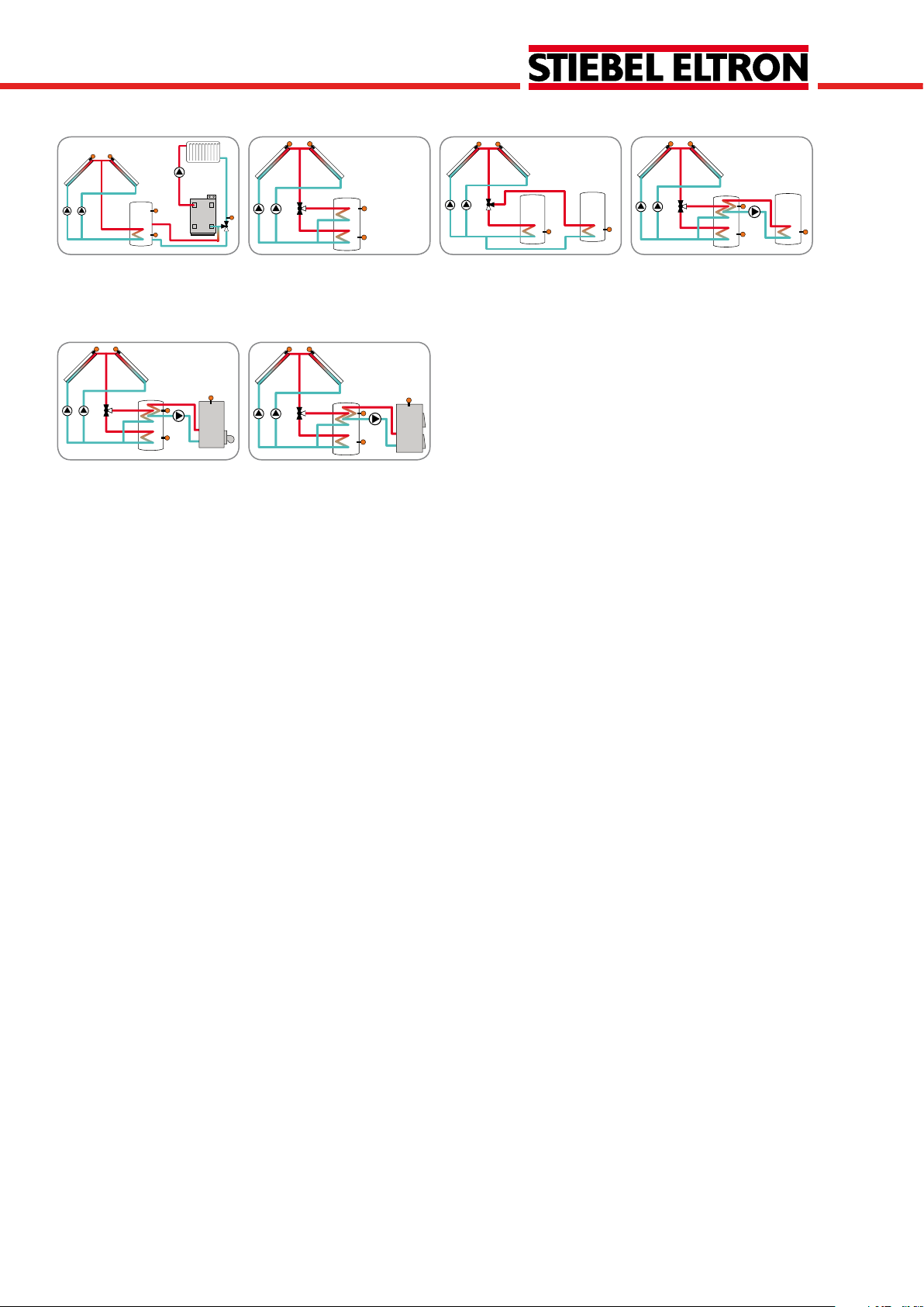
21 22 23 24
Solar system with east-/west
collectors and heating circuit
return preheating (page 51)
Solar system with vertical
tank loading and east-/west
collectors (page 53)
25 26
Solar system with east-/
west collectors, vertical tank
loading and and thermostatic
backup heating (page 62)
Solar system with east-/west
collectors, vertical tank loading and backup heating with
solid fuel boiler (page 65)
Solar system with east-/west
collectors and 2 tanks (valve
logic) (page 56)
Solar system with east-/
west collectors, vertical tank
loading and heat exchange
(page 59)
| 8
© Stiebel 11091_SOM_9s.monus.indd
Page 9

SOM 9s
Temp.Sensor
Pt1000
L
R3
R2
R1
GND
S1
S2
S3
S4
S5
VBus
PWM 1
PWM 2
N
R4
V40
L'
VFS
RPS
out in
2.6 System layouts
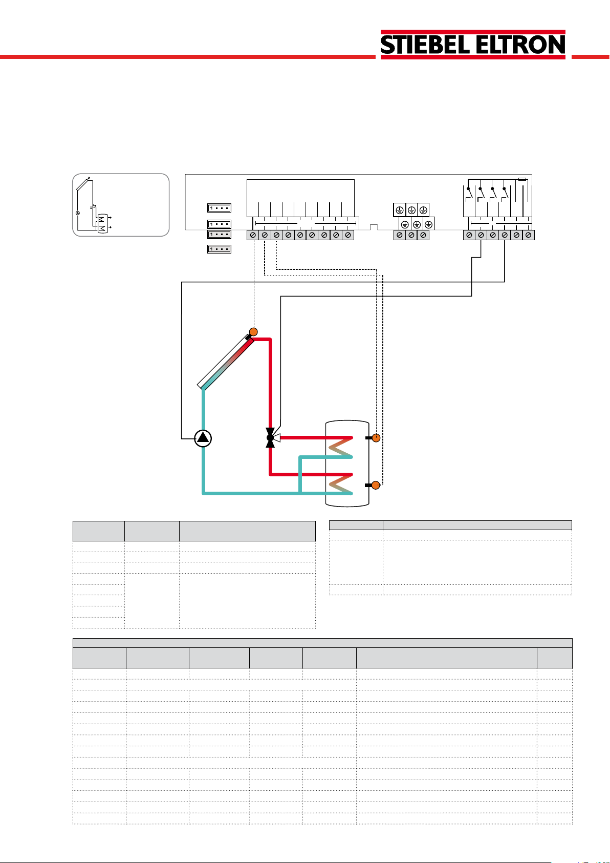
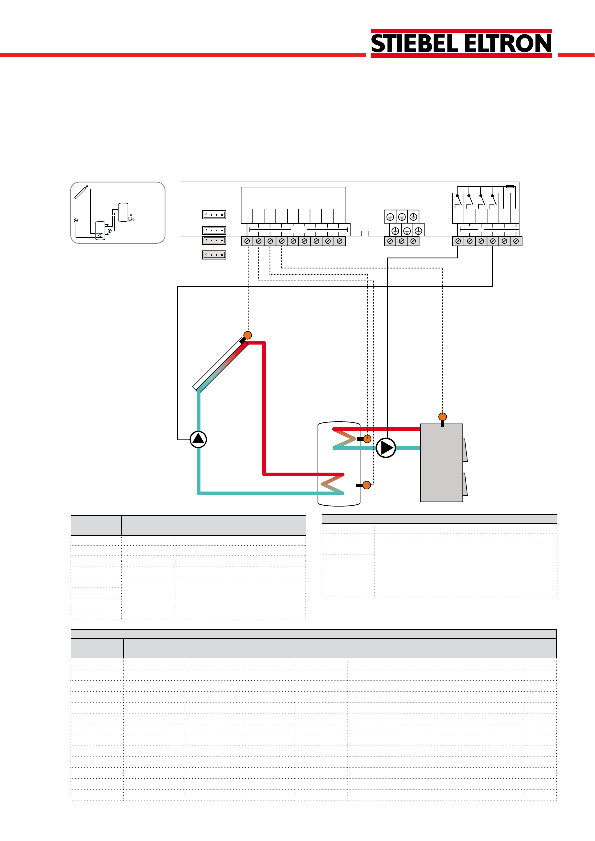
System 1
Standard solar system with 1 tank
The controller calculates the temperature difference between collector sensor S1 and tank sensor S2. If the difference is larger than or identical to the adjusted switch-on
S1
temperature difference, the pump (R1) will be switched on
and the tank will be loaded until the switch-off temperature
difference or the maximum tank temperature is reached.
R1
S2
Relay Description
R1 Solar pump
R2 optional:
R3
R4
Thermal disinfection
Booster pump
Parallel relay
Heat dump
Change to Description Page
9 |
Sensor/Terminal
S1 TCOL Temperature collector
S2 TSTB Temperature tank bottom
S3 Optional sensor for measurement
S4
Designation Description
purposes or options
S5
VFS
RPS
V40
Adjustment channels
Channel Sub channel 1 Sub channel 2 Factory
setting
ARR 1 System 78
LOAD > Loading
DT O 12 °R Switch-on temperature difference 78
DT F 8 °R Switch-off temperature difference 78
DT S 20 °R Set temperature difference 78
RIS 4 °R Rise 78
S MAX 140 °F Tank maximum limitation 78
SMAXS 2 Sensor tank max 79
COL > Collector
CEM 270 °F Collector emergency temperature 80
OCCO** OFF Option collector cooling 80
CMAX 230 °F Maximum collector temperature 80
OCMI OFF Option collector minimum limitation 80
© Stiebel 11091_SOM_9s.monus.indd
CMIN 50 °F Minimum collector temperature 80
Page 10

SOM 9s
Adjustment channels
Channel Sub channel 1 Sub channel 2 Factory
OTCO OFF Option evacuated tube collector function 81
TCST 07:00 Evacuated tube collector starting time 81
TCEN 19:00 Evacuated tube collector ending time 81
TCRU 30 s Evacuated tube collector runtime 81
TCIN 30 min Evacuated tube collector standstill interval 81
OCFR OFF Option collector frost protection 82
CFR O 40 °F Antifreeze temperature collector on 82
CFR F 42 °F Antifreeze temperature collector off 82
LLOGI > Loading logic
ODB > OFF Drainback option 84
OOVRU* OFF Overrun option 84
COOL > Cooling functions
OSYC** OFF System cooling 85
OSTC OFF Tank cooling 85
OHDP** OFF Heat dump 85
PUMP > Pump speed
PUMP1 OnOF Speed variant pump 1 79
PUMP2 OnOF Speed variant pump 2 79
PUMP3 OnOF Speed variant pump 3 79
MAN > Manual mode
MAN1 Auto Manual mode 1 88
MAN2 Auto Manual mode 2 88
MAN3 Auto Manual mode 3 88
MAN4 Auto Manual mode 4 88
BLPR >
OTDIS > OFF Thermal disinfection option 89
OPARR > OFF Parallel relay option 90
OHQM > OFF Energy metering option 90
GFDS > OFF Registration Grundfos sensors 90
PRS* > OFF Pressure monitoring option 92
DATE > OFF Enter date 92
LANG > En Language 93
UNIT > °F Unit 92
OSDC > SD card option 93
CODE 0000 User code 96
RESET OFF Factory setting
* This channel is only available if the Grundfos sensors have been registered in the GFDS channel.
** are blocked against each other
setting
OFF Blocking protection 88
Change to Description Page
| 10
© Stiebel 11091_SOM_9s.monus.indd
Page 11
SOM 9s
R4
R1
S4
S3
S2
S1
Temp.Sensor
Pt1000
L
R3
R2
R1
GND
S1
S2
S3
S4
S5
VBus
PWM 1
PWM 2
N
R4
V40
L'
VFS
RPS
out in
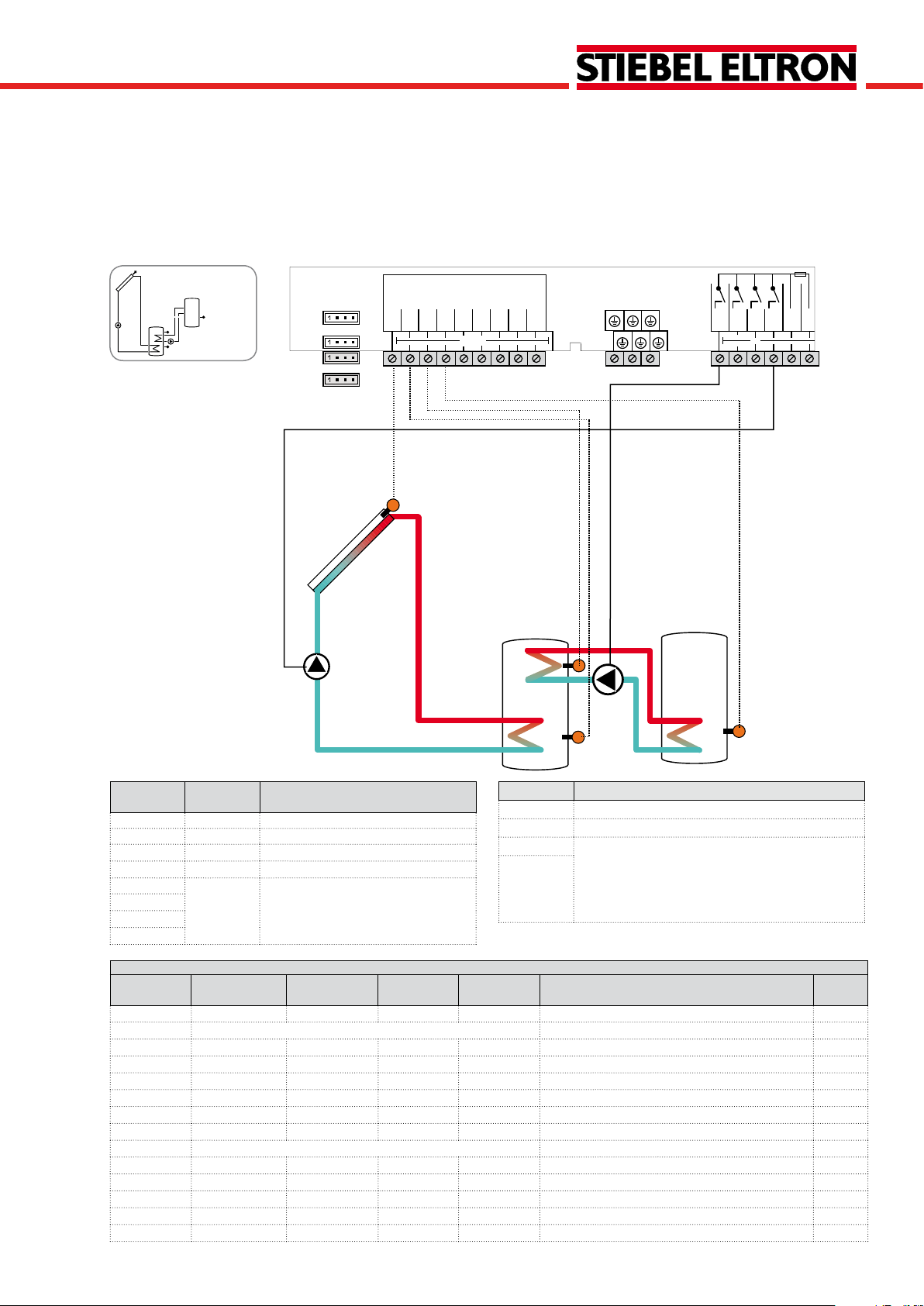
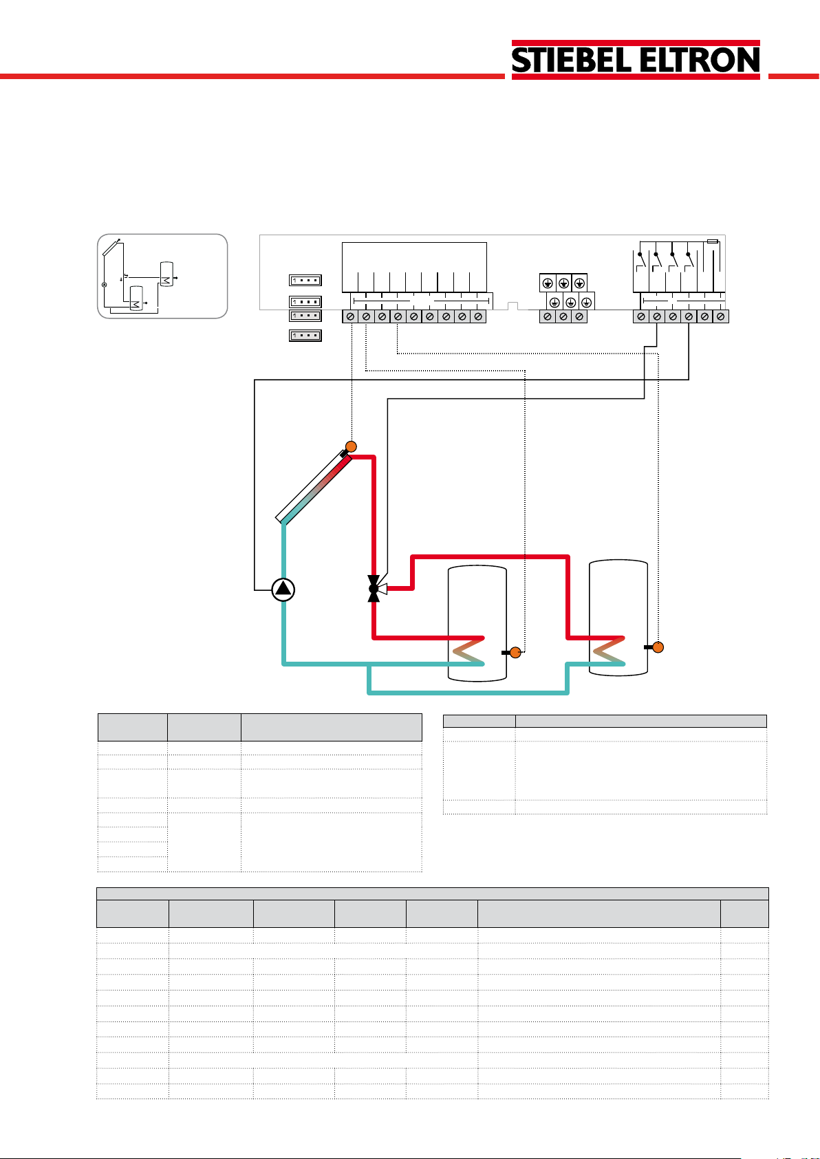
System 2
Solar system with 2 tanks and heat exchange
The controller calculates the temperature difference between collector sensor S1 and tank sensor S2. If the difference is larger than or identical to the adjusted switch-on
temperature difference, the pump (R1) will be switched on
and the tank will be loaded until the switch-off temperature
difference or the maximum tank temperature is reached.
Heat exchange between S3 and S4 is possible.
Sensor/Terminal
S1 TCOL Temperature collector
S2 TST1B Temperature tank 1 bottom
S3 TST1T Temperature tank 1 top
S4 TST2B Temperature tank 2 top
S5 Optional sensor for measurement
VFS
RPS
Designation Description
purposes or options
Relay Description
R1 Solar pump
R2 Heat exchange pump
R3 optional:
R4
Thermal disinfection
Booster pump
Parallel relay
Heat dump
V40
Adjustment channels
Channel Sub channel 1 Sub channel 2 Factory
Change to Description Page
setting
ARR 1 2 System 78
LOAD > Loading
DT O 12 °R Switch-on temperature difference 78
DT F 8 °R Switch-off temperature difference 78
DT S 20 °R Set temperature difference 78
RIS 4 °R Rise 78
S MAX 140 °F Tank maximum limitation 79
SMAXS 2 Sensor tank max 79
COL > Collector
CEM 270 °F Collector emergency temperature 80
OCCO** OFF Option collector cooling 80
CMAX 230 °F Maximum collector temperature 80
OCMI OFF Option collector minimum limitation 80
© Stiebel 11091_SOM_9s.monus.indd
CMIN 50 °F Minimum collector temperature 80
11 |
Page 12

SOM 9s
Adjustment channels
Channel Sub channel 1 Sub channel 2 Factory
OTCO OFF Option evacuated tube collector function 81
TCST 07:00 Evacuated tube collector starting time 81
TCEN 19:00 Evacuated tube collector ending time 81
TCRU 30 s Evacuated tube collector runtime 81
TCIN 30 min Evacuated tube collector standstill interval 81
OCFR OFF Option collector frost protection 82
CFR O 40 °F Antifreeze temperature collector on 82
CFR F 42 °F Antifreeze temperature collector off 82
LLOGI > Loading logic
ODB > OFF Drainback option 84
OOVRU* OFF Overrun option 84
COOL > Cooling functions
OSYC** OFF System cooling 85
OSTC OFF Tank cooling 85
OHDP** OFF Heat dump 85
DT3 > Heat exchange
DT3O 12 °R Switch-on difference 86
DT3F 8 °R Switch-off difference 86
DT3S 20 °R Set difference 86
RIS3 4 °R Rise 86
MAX3O 140 °F Switch-on temperature (maximum limitation) 86
MAX3F 136 °F Switch-off temperature (maximum limitation) 86
MIN3O 40 °F Switch-on temperature (minimum limitation) 86
MIN3F 50 °F Switch-off temperature (minimum limitation) 86
S2DT3 4 Reference sensor heat sink 86
PUMP > Pump speed
PUMP1 OnOF Speed variant pump 1 79
PUMP2 OnOF Speed variant pump 2 79
PUMP3 OnOF Speed variant pump 3 79
MAN > Manual mode
MAN1 Auto Manual mode 1 88
MAN2 Auto Manual mode 2 88
MAN3 Auto Manual mode 3 88
MAN4 Auto Manual mode 4 88
BLPR >
OTDIS > OFF Thermal disinfection option 89
OPARR > OFF Parallel relay option 90
OHQM > OFF Energy metering option 90
GFDS > OFF Registration Grundfos sensors 90
PRS* > OFF Pressure monitoring option 92
DATE> OFF Enter date 92
LANG > En Language 93
UNIT > °F Unit 92
OSDC > SD card option 93
CODE 0000 User code 96
RESET OFF Factory setting
* This channel is only available if the Grundfos sensors have been registered in the GFDS channel.
** are blocked against each other
setting
OFF Blocking protection 88
Change to Description Page
| 12
© Stiebel 11091_SOM_9s.monus.indd
Page 13
SOM 9s
System 3
Solar system with 1 tank and backup heating
The controller calculates the temperature difference between collector sensor S1 and tank sensor S2. If the difference is larger than or identical to the adjusted switch-on
temperature difference, the pump (R1) will be switched on
and the tank will be loaded until the switch-off temperature
difference or the maximum tank temperature is reached.
Domestic hot water backup heating (R4) can be carried out
with a thermostat function (S3). If the value at S3 reaches
the switch-on temperature for the backup heating, the relay
is energized. If the value exceeds the switch-off temperature
for the backup heating, the relay is switched off again.
R1
VFS
RPS
Te mp. Sensor
Pt1000
S1
S2
S3
S1
S4
S5
GND
out in
PWM 1
PWM 2
L
V40
VBus
S3
R4
R4
L'
R1
R3
R2
N
S2
Sensor/Terminal
S1 TCOL Temperature collector
S2 TSTB Temperature tank bottom
S3 TSTT Temperature tank top
S4 Optional sensor for measurement
S5
VFS
RPS
V40
Adjustment channels
Channel Sub channel 1 Sub channel 2
ARR 1 3 System 78
LOAD > Loading
COL > Collector
© Stiebel 11091_SOM_9s.monus.indd
Designation Description
Relay Description
R1 Solar pump
R2 optional:
R3
Thermal disinfection
Booster pump
Parallel relay
purposes or options
Heat dump
R4 Backup heating/tank loading pump
Factory
setting
Change to Description Page
DT O 12 °R Switch-on temperature difference
DT F 8 °R Switch-off temperature difference
DT S 20 °R Set temperature difference
RIS 4 °R Rise
S MAX
SMAXS 2
140 °F
Tank maximum limitation
Sensor tank max 79
CEM 270 °F Collector emergency temperature
OCCO**
OFF
Option collector cooling
78
78
78
78
79
80
80
13 |
Page 14

SOM 9s
Adjustment channels
Channel Sub channel 1 Sub channel 2
CMAX 230 °F Maximum collector temperature 80
OCMI
CMIN 50 °F Minimum collector temperature 80
OTCO OFF Option evacuated tube collector function 81
TCST 07:00 Evacuated tube collector starting time 81
TCEN 19:00 Evacuated tube collector ending time 81
TCRU 30 s Evacuated tube collector runtime 81
TCIN 30 min Evacuated tube collector standstill interval 81
OCFR OFF Option collector frost protection 82
CFR O 40 °F Antifreeze temperature collector on 82
CFR F 42 °F Antifreeze temperature collector off 82
LLOGI > Loading logic
ODB > OFF Drainback option 84
OOVRU* OFF Overrun option 84
COOL > Cooling functions
OSYC** OFF System cooling 85
OSTC OFF Tank cooling 85
OHDP** OFF Heat dump 85
AH > Backup heating option
AH O 110 °F Backup heating switch-on temperature 87
AH F 120 °F Backup heating switch-off temperature 87
t1O 06:00 Switch-on time 1 88
t1F 22:00 Switch-off time 1 88
t2O 00:00 Switch-on time 2 88
t2F 00:00 Switch-off time 2 88
t3O 00:00 Switch-on time 3 88
t3F 00:00 Switch-off time 3 88
PUMP > Pump speed
PUMP1 OnOF Speed variant pump 1 79
PUMP2 OnOF Speed variant pump 2 79
PUMP3 OnOF Speed variant pump 3 79
MAN > Manual mode
MAN1 Auto Manual mode 1 88
MAN2 Auto Manual mode 2 88
MAN3 Auto Manual mode 3 88
MAN4 Auto Manual mode 4 88
BLPR >
OTDIS > OFF Thermal disinfection option 89
OPARR > OFF Parallel relay option 90
OHQM > OFF Energy metering option 90
GFDS > OFF Registration Grundfos sensors 90
PRS* > OFF Pressure monitoring option 92
DATE> Enter date 92
LANG > En Language 93
UNIT > °F Unit 92
OSDC > SD card option 93
CODE 0000 User code 96
RESET OFF Factory setting
* This channel is only available if the Grundfos sensors have been registered in the GFDS channel.
** are blocked against each other
Factory
setting
OFF Option collector minimum limitation 80
OFF Blocking protection 88
Change to Description Page
| 14
© Stiebel 11091_SOM_9s.monus.indd
Page 15
SOM 9s
R3
R1
S3
S2
S1
Temp.Sensor
Pt1000
L
R3
R2
R1
GND
S1
S2
S3
S4
S5
VBus
PWM 1
PWM 2
N
R4
V40
L'
VFS
RPS
out in
System 4
Solar system with 1 tank and 3-port valve for vertical tank loading
The controller compares the temperature at sensor S1 to
the temperatures at sensors S2 and S3. If the measured
temperature differences are higher than the adjusted switchon temperature differences, the pump (R1) will be activated
and the corresponding tank zone will be loaded up to the
adjusted maximum temperature via the valve (R3). The priority logic effects prior loading of the upper zone of the tank.
Note: 3-port valve normally open - tank bottom
Relay Description
R1 Solar pump
R2/R4 optional:
Thermal disinfection
Parallel relay
Heat dump
R3 3-port valve tank top/bottom
Change to Description Page
Sensor/Terminal
S1 TCOL Temperature collector
S2 TSTB Temperature tank bottom
S3 TSTT Temperature tank top
S4 Optional sensor for measurement
S5
Designation Description
purposes or options
VFS
RPS
V40
Adjustment channels
Channel Sub channel 1 Sub channel 2 Factory
setting
ARR 1 4 System 78
LOAD1 > Loading 1
DT1O 12 °R Switch-on temperature difference 1 78
DT1F 8 °R Switch-off temperature difference 1 78
DT1S 20 °R Set temperature difference 1 78
RIS1 4 °R Rise 1 78
S1MAX 140 °F Tank maximum limitation 1 78
SMXS1 2 Sensor tank max 1 79
LOAD2 > Loading 2
DT2O 12 °R Switch-on temperature difference 2 78
DT2F 8 °R Switch-off temperature difference 2 78
DT2S 20 °R Set temperature difference 2 78
RIS2 4 °R Rise 2 78
© Stiebel 11091_SOM_9s.monus.indd
S2MAX 140 °F Tank maximum limitation 2 78
15 |
Page 16

SOM 9s
Adjustment channels
Channel Sub channel 1 Sub channel 2 Factory
LST2 ON Loading tank 2 79
COL > Collector
CEM 270 °F Collector emergency temperature 80
OCCO** OFF Option collector cooling 80
CMAX 230 °F Maximum collector temperature 80
OCMI OFF Option collector minimum limitation 80
CMIN 50 °F Minimum collector temperature 80
OTCO OFF Option evacuated tube collector function 81
TCST 07:00 Evacuated tube collector starting time 81
TCEN 19:00 Evacuated tube collector ending time 81
TCRU 30 s Evacuated tube collector runtime 81
TCIN 30 min Evacuated tube collector standstill interval 81
OCFR OFF Option collector frost protection 82
CFR O 40 °F Antifreeze temperature collector on 82
CFR F 42 °F Antifreeze temperature collector off 82
LLOGI > Loading logic
PRIO Priority logic 82
PRIO 2 Priority logic 82
OSTS OFF Tank set option 83
TST1 120 °F Set tank temperature tank 1 83
TST2 120 °F Set tank temperature tank 2 83
tLB 2 min Loading break time 82
tRUN 15 min Circulation runtime 82
PSPEE OFF Pause speed option 83
PDELA OFF Pump delay option 83
OOVRU* OFF Overrun option 84
COOL > Cooling functions
OSYC** OFF System cooling 85
OSTC OFF Tank cooling 85
OHDP** OFF Heat dump 85
PUMP > Pump speed
PUMP1 OnOF Speed variant pump 1 79
PUMP2 OnOF Speed variant pump 2 79
PUMP3 OnOF Speed variant pump 3 79
MAN > Manual mode
MAN1 Auto Manual mode 1 88
MAN2 Auto Manual mode 2 88
MAN3 Auto Manual mode 3 88
MAN4 Auto Manual mode 4 88
BLPR >
OTDIS > OFF Thermal disinfection option 89
OPARR > OFF Parallel relay option 90
OHQM > OFF Energy metering option 90
GFDS > OFF Registration Grundfos sensors 90
PRS* > OFF Pressure monitoring option 92
DATE> OFF Enter date 92
LANG > En Language 93
UNIT > °F Unit 92
OSDC > SD card option 93
CODE 0000 User code 96
RESET OFF Factory setting
* This channel is only available if the Grundfos sensors have been registered in the GFDS channel.
** are blocked against each other
setting
OFF Blocking protection 88
Change to Description Page
| 16
© Stiebel 11091_SOM_9s.monus.indd
Page 17
SOM 9s
R3
R1
S4
S2
S1
Temp.Sensor
Pt1000
L
R3
R2
R1
GND
S1
S2
S3
S4
S5
VBus
PWM 1
PWM 2
N
R4
V40
L'
VFS
RPS
out in
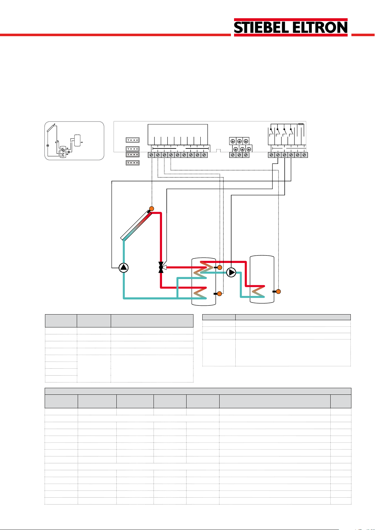
System 5
2-tanksystemwithvalvelogic,1pump,3sensorsand3-portvalve
The controller compares the temperature at sensor S1 to
the temperatures at sensors S2 and S4. If the measured temperature differences are higher than the adjusted switch-on
temperature differences, the pump (R1) will be activated and
the corresponding tank will be loaded up to the adjusted
maximum temperature via the valve (R3). Tank 1 is loaded
with priority.
Note: 3-port valve normally open - tank 1 (S2)
Sensor/Terminal
S1 TCOL Temperature collector
S2 TST1B Temperature tank 1 bottom
S3 Optional sensor for measurement
S4 TST2B Temperature tank 2 bottom
S5 Optional sensor for measurement
VFS
RPS
V40
Adjustment channels
Channel Sub channel 1 Sub channel 2 Factory
ARR
LOAD1 >
LOAD2 >
© Stiebel 11091_SOM_9s.monus.indd
Designation Description
Relay Description
R1 Solar pump
R2/R4 optional:
Thermal disinfection
Parallel relay
purposes or options
Heat dump
R3 3-port valve tank 1 / 2
purposes or options
Change to Description Page
setting
1 5 System 78
Loading 1
DT1O 12 °R Switch-on temperature difference 1
DT1F 8 °R Switch-off temperature difference 1
DT1S 20 °R Set temperature difference 1
RIS1 4 °R Rise 1
S1MAX
SMXS1 2
140 °F
Tank maximum limitation 1
Sensor tank max 1 79
Loading 2
DT2O 12 °R Switch-on temperature difference 2
DT2F
8 °R
Switch-off temperature difference 2
78
78
78
78
78
78
78
17 |
Page 18

SOM 9s
Adjustment channels
Channel Sub channel 1 Sub channel 2 Factory
setting
DT2S
RIS2
S2MAX
SMXS2 4 Sensor tank max 2 79
LST2 ON Loading tank 2 79
COL > Collector
CEM 270 °F Collector emergency temperature 80
OCCO** OFF Option collector cooling 80
CMAX 230 °F Maximum collector temperature 80
OCMI OFF Option collector minimum limitation 80
CMIN 50 °F Minimum collector temperature 80
OTCO OFF Option evacuated tube collector function 81
TCST 07:00 Evacuated tube collector starting time 81
TCEN 19:00 Evacuated tube collector ending time 81
TCRU 30 s Evacuated tube collector runtime 81
TCIN 30 min Evacuated tube collector standstill interval 81
OCFR OFF Option collector frost protection 82
CFR O 40 °F Antifreeze temperature collector on 82
CFR F 42 °F Antifreeze temperature collector off 82
FRPST 1 Antifreeze tank selection 82
LLOGI > Loading logic
PRIO Priority logic 82
PRIO 1 Priority logic 82
OSTS OFF Tank set option 83
TST1 120 °F Set tank temperature tank 1 83
TST2 120 °F Set tank temperature tank 2 83
tLB 2 min Loading break time 82
tRUN 15 min Circulation runtime 82
PSPEE OFF Pause speed option 83
PDELA OFF Pump delay option 83
OOVRU* OFF Overrun option 84
COOL > Cooling functions
OSYC** OFF System cooling 85
OSTC OFF Tank cooling 85
OHDP** OFF Heat dump 85
PUMP > Pump speed
PUMP1 OnOF Speed variant pump 1 79
PUMP2 OnOF Speed variant pump 2 79
PUMP3 OnOF Speed variant pump 3 79
MAN > Manual mode
MAN1 Auto Manual mode 1 88
MAN2 Auto Manual mode 2 88
MAN3 Auto Manual mode 3 88
MAN4 Auto Manual mode 4 88
BLPR >
OTDIS > OFF Thermal disinfection option 89
OPARR > OFF Parallel relay option 90
OHQM > OFF Energy metering option 90
GFDS > OFF Registration Grundfos sensors 90
PRS* > OFF Pressure monitoring option 92
DATE> Enter date 92
LANG > En Language 93
UNIT > °F Unit 92
OSDC > SD card option 93
CODE 0000 User code 96
RESET OFF Factory setting
* This channel is only available if the Grundfos sensors have been registered in the GFDS channel.
** are blocked against each other
20 °R
4 °R
140 °F
OFF Blocking protection 88
Change to Description Page
Set temperature difference 2
Rise 2
Tank maximum limitation 2
78
78
78
| 18
© Stiebel 11091_SOM_9s.monus.indd
Page 19
SOM 9s
R2R1
S4
S2
S1
Temp.Sensor
Pt1000
L
R3
R2
R1
GND
S1
S2
S3
S4
S5
VBus
PWM 1
PWM 2
N
R4
V40
L'
VFS
RPS
out in
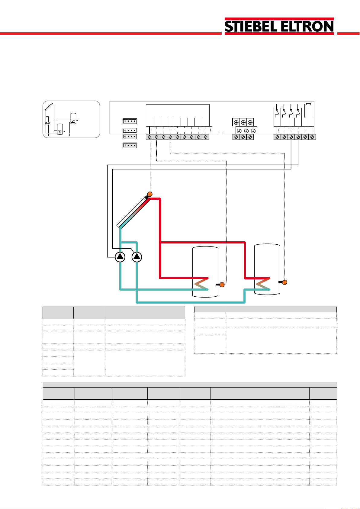
System 6
2-tank solar system with pump logic
The controller compares the temperature at sensor S1 to
the temperatures at sensors S2 and S4. If the measured
temperature differences are higher than the adjusted switchon temperature differences, the pump (R1 and R2) will be
activated and the corresponding tank will be loaded up to
the adjusted maximum temperature at most.
Sensor/Terminal
S1 TCOL Temperature collector
S2 TST1B Temperature tank 1 bottom
S3 Optional sensor for measurement
S4 TST2B Temperature tank 2 bottom
S5 Optional sensor for measurement
VFS
Designation Description
purposes or options
purposes or options
Relay Description
R1 Solar pump tank 1
R2 Solar pump tank 2
R3 optional:
R4
Thermal disinfection
Parallel relay
Heat dump
RPS
V40
Adjustment channels
Channel Sub channel 1 Sub channel 2 Factory
setting
ARR 1 6 System
Change to Description Page
78
LOAD1 > Loading 1
DT1O 12 °R Switch-on temperature difference 1 78
DT1F 8 °R Switch-off temperature difference 1 78
DT1S 20 °R Set temperature difference 1 78
RIS1 4 °R Rise 1 78
S1MAX 140 °F Tank maximum limitation 1 78
SMXS1 2 Sensor tank max 1 79
LOAD2 > Loading 2
DT2O 12 °R Switch-on temperature difference 2 78
DT2F 8 °R Switch-off temperature difference 2 78
DT2S 20 °R Set temperature difference 2 78
© Stiebel 11091_SOM_9s.monus.indd
RIS2 4 °R Rise 2 78
19 |
Page 20

SOM 9s
Adjustment channels
Channel Sub channel 1 Sub channel 2 Factory
S2MAX 140 °F Tank maximum limitation 2 78
SMXS2 4 Sensor tank max 2 79
LST2 ON Loading tank 2 79
COL > Collector
CEM 270 °F Collector emergency temperature 80
OCCO** OFF Option collector cooling 80
CMAX 230 °F Maximum collector temperature 80
OCMI OFF Option collector minimum limitation 80
CMIN 50 °F Minimum collector temperature 80
OTCO OFF Option evacuated tube collector function 81
TCST 07:00 Evacuated tube collector starting time 81
TCEN 19:00 Evacuated tube collector ending time 81
TCRU 30 s Evacuated tube collector runtime 81
TCIN 30 min Evacuated tube collector standstill interval 81
OCFR OFF Option collector frost protection 82
CFR O 40 °F Antifreeze temperature collector on 82
CFR F 42 °F Antifreeze temperature collector off 82
FRPST 1 Antifreeze tank selection 82
LLOGI > Loading logic
PRIO Priority logic 82
PRIO 1 Priority logic 82
OSTS OFF Tank set option 83
TST1 120 °F Set tank temperature tank 1 83
TST2 120 °F Set tank temperature tank 2 83
OSE OFF Spread function option 83
DTSE 40 Spread difference 83
tLB 2 min Loading break time 82
tRUN 15 min Circulation runtime 82
PSPEE OFF Pause speed option 83
PDELA OFF Pump delay option 83
OOVRU* OFF Overrun option 84
COOL > Cooling functions
OSYC** OFF System cooling 85
OSTC OFF Tank cooling 85
OHDP** OFF Heat dump 85
PUMP > Pump speed
PUMP1 OnOF Speed variant pump 1 79
PUMP2 OnOF Speed variant pump 2 79
PUMP3 OnOF Speed variant pump 3 79
MAN > Manual mode
MAN1 Auto Manual mode 1 88
MAN2 Auto Manual mode 2 88
MAN3 Auto Manual mode 3 88
MAN4 Auto Manual mode 4 88
BLPR >
OTDIS > OFF Thermal disinfection option 89
OPARR > OFF Parallel relay option 90
OHQM > OFF Energy metering option 90
GFDS > OFF Registration Grundfos sensors 90
PRS* > OFF Pressure monitoring option 92
DATE> Enter date 92
LANG > En Language 93
UNIT > °F Unit 92
OSDC > SD card option 93
CODE 0000 User code 96
RESET OFF Factory setting
* This channel is only available if the Grundfos sensors have been registered in the GFDS channel.
** are blocked against each other
setting
OFF Blocking protection 88
Change to Description Page
| 20
© Stiebel 11091_SOM_9s.monus.indd
Page 21
SOM 9s
Temp.Sensor
Pt1000
L
R3
R2
R1
GND
S1
S2
S3
S4
S5
VBus
PWM 1
PWM 2
N
R4
V40
L'
VFS
RPS
out in
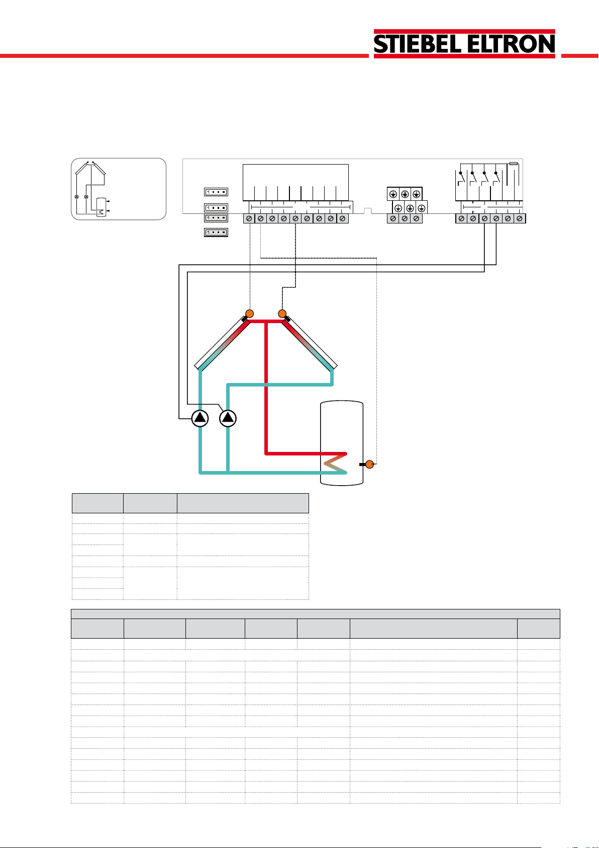
System 7
Solar system with east-/west collectors
The controller compares the temperatures at the collector
sensors S1 and S5 to the tank temperature at sensor S2.
If one of the measured temperature differences is higher
than the adjusted switch-on temperature differences, the
corresponding pump (R1, R2) will be activated and the tank
will be loaded.
S1
S5
R2R1
Sensor/Terminal
S1 TCOL1 Temperature collector 1
S2 TSTB Temperature tank bottom
S3 Optional sensor for measurement
S4
S5 TCOL2 Temperature collector 2
VFS Optional sensor for measurement
RPS
V40
Designation Description
purposes or options
purposes or options
S2
Adjustment channels
Channel Sub channel 1 Sub channel 2 Factory
Change to Description Page
setting
ARR 1 7 System
78
LOAD > Loading
DT O 12 °R Switch-on temperature difference 78
DT F 8 °R Switch-off temperature difference 78
DT1S 20 °R Set temperature difference 78
RIS 4 °R Rise 78
S MAX 140 °F Tank maximum limitation 78
SMAXS 2 Sensor tank max 79
COL 1 > Collector 1
CEM1 270 °F Collector emergency temperature 1 80
OCCO1** OFF Option collector cooling 1 80
CMAX1 230 °F Maximum collector temperature 1 80
OCMI1 OFF Option collector minimum limitation 1 80
CMIN1 50 °F Minimum collector temperature 1 80
© Stiebel 11091_SOM_9s.monus.indd
OTCO1 OFF Option evacuated tube collector function 1 81
21 |
Page 22

SOM 9s
Adjustment channels
Channel Sub channel 1 Sub channel 2 Factory
TCST1 07:00 Evacuated tube collector starting time 1 81
TCEN1 19:00 Evacuated tube collector ending time 1 81
TCRU1 30 s Evacuated tube collector runtime 1 81
TCIN1 30 min Evacuated tube collector standstill interval 1 81
OCFR OFF Option collector frost protection 82
CFR O 40 °F Antifreeze temperature collector on 82
CFR F 42 °F Antifreeze temperature collector off 82
COL 2 > Collector 2
CEM2 270 °F Collector emergency temperature 2 80
OCCO2** OFF Option collector cooling 2 80
CMAX2 230 °F Maximum collector temperature 2 80
OCMI2 OFF Option collector minimum limitation 2 80
CMIN2 50 °F Minimum collector temperature 2 80
OTCO2 OFF Option evacuated tube collector function 2 81
TCST2 07:00 Evacuated tube collector starting time 2 81
TCEN2 19:00 Evacuated tube collector ending time 2 81
TCRU2 30 s Evacuated tube collector runtime 2 81
TCIN2 30 min Evacuated tube collector standstill interval 2 81
LLOGI > Loading logic
OOVRU* OFF Overrun option 84
COOL > Cooling functions
OSYC** OFF System cooling 85
OSTC OFF Tank cooling 85
OHDP** OFF Heat dump 85
PUMP > Pump speed
PUMP1 OnOF Speed variant pump 1 79
PUMP2 OnOF Speed variant pump 2 79
PUMP3 OnOF Speed variant pump 3 79
MAN > Manual mode
MAN1 Auto Manual mode 1 88
MAN2 Auto Manual mode 2 88
MAN3 Auto Manual mode 3 88
MAN4 Auto Manual mode 4 88
BLPR >
OTDIS > OFF Thermal disinfection option 89
OPARR > OFF Parallel relay option 90
OHQM > OFF Energy metering option 90
GFDS > OFF Registration Grundfos sensors 90
PRS* > OFF Pressure monitoring option 92
DATE> Enter date 92
LANG > En Language 93
UNIT > °F Unit 92
OSDC > SD card option 93
CODE 0000 User code 96
RESET OFF Factory setting
* This channel is only available if the Grundfos sensors have been registered in the GFDS channel.
** are blocked against each other
setting
OFF Blocking protection 88
Change to Description Page
| 22
© Stiebel 11091_SOM_9s.monus.indd
Page 23
SOM 9s
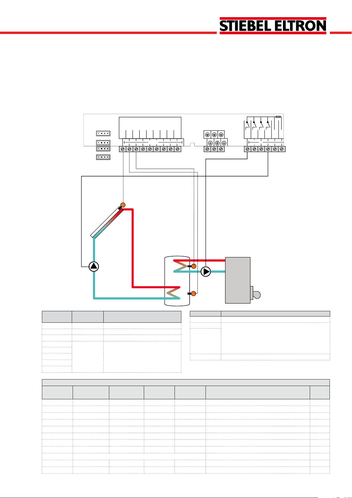
System 8
Solar system with 1 tank and backup heating with solid fuel boiler
The controller calculates the temperature difference between collector sensor S1 and tank sensor S2. If the difference is larger than or identical to the adjusted switch-on
temperature difference, the pump (R1) will be switched on
and the tank will be loaded until the switch-off temperature
difference or the maximum tank temperature is reached.
With another temperature differential function (S4/S3),
backup heating of the tank can be carried out with a solid
fuel boiler (R3).
R1
VFS
RPS
Te mp. Sensor
Pt1000
S1
S2
S3
S1
S4
S5
GND
out in
PWM 1
PWM 2
L
V40
VBus
R4
L'
R1
R3
R2
N
S4
S3
R3
S2
Sensor/Ter-
Designation Description
minal
S1 TCOL Temperature collector
S2 TSTB Temperature tank bottom
S3 TSTT Temperature tank top
S4 TSFB Temperature solid fuel boiler
S5 Optional sensor for measurement
VFS
purposes or options
RPS
V40
Adjustment channels
Channel Sub channel 1 Sub channel 2 Factory
setting
ARR 1 8 System
LOAD > Loading
DT O 12 °R Switch-on temperature difference 78
DT F 8 °R Switch-off temperature difference 78
DT S 20 °R Set temperature difference 78
RIS 4 °R Rise 78
S MAX 140 °F Tank maximum limitation 78
SMAXS 2 Sensor tank max 79
COL > Collector
CEM 270 °F Collector emergency temperature 80
OCCO** OFF Option collector cooling 80
CMAX 230 °F Maximum collector temperature 80
© Stiebel 11091_SOM_9s.monus.indd
OCMI OFF Option collector minimum limitation 80
Relay Description
R1 Solar pump
R3 Loading pump solid fuel boiler
R2 optional:
R4
Thermal disinfection
Booster pump
Parallel relay
Heat dump
Change to Description Page
78
23 |
Page 24

SOM 9s
Adjustment channels
Channel Sub channel 1 Sub channel 2 Factory
CMIN 50 °F Minimum collector temperature 80
OTCO OFF Option evacuated tube collector function 81
TCST 07:00 Evacuated tube collector starting time 81
TCEN 19:00 Evacuated tube collector ending time 81
TCRU 30 s Evacuated tube collector runtime 81
TCIN 30 min Evacuated tube collector standstill interval 81
OCFR OFF Option collector frost protection 82
CFR O 40 °F Antifreeze temperature collector on 82
CFR F 42 °F Antifreeze temperature collector off 82
LLOGI > Loading logic
ODB > OFF Drainback option 84
OOVRU* OFF Overrun option 84
COOL > Cooling functions
OSYC** OFF System cooling 85
OSTC OFF Tank cooling 85
OHDP** OFF Heat dump 85
DT3 > Solid fuel boiler
DT3O 12 °R Switch-on difference 86
DT3F 8 °R Switch-off difference 86
DT3S 20 °R Set difference 86
RIS3 4 °R Rise 86
MAX3O 140 °F Switch-on temperature (maximum limitation) 86
MAX3F 136 °F Switch-off temperature (maximum limitation) 86
MIN3O 140 °F Switch-on temperature (minimum limitation) 86
MIN3F 150 °F Switch-off temperature (minimum limitation) 86
S2DT3 3 Reference sensor heat sink 87
PUMP > Pump speed
PUMP1 OnOF Speed variant pump 1 79
PUMP2 OnOF Speed variant pump 2 79
PUMP3 OnOF Speed variant pump 3 79
MAN > Manual mode
MAN1 Auto Manual mode 1 88
MAN2 Auto Manual mode 2 88
MAN3 Auto Manual mode 3 88
MAN4 Auto Manual mode 4 88
BLPR >
OTDIS > OFF Thermal disinfection option 89
OPARR > OFF Parallel relay option 90
OHQM > OFF Energy metering option 90
GFDS > OFF Registration Grundfos sensors 90
PRS* > OFF Pressure monitoring option 92
DATE> Enter date 92
LANG > En Language 93
UNIT > °F Unit 92
OSDC > SD card option 93
CODE 0000 User code 96
RESET OFF Factory setting
* This channel is only available if the Grundfos sensors have been registered in the GFDS channel.
** are blocked against each other
setting
OFF Blocking protection 88
Change to Description Page
| 24
© Stiebel 11091_SOM_9s.monus.indd
Page 25
SOM 9s
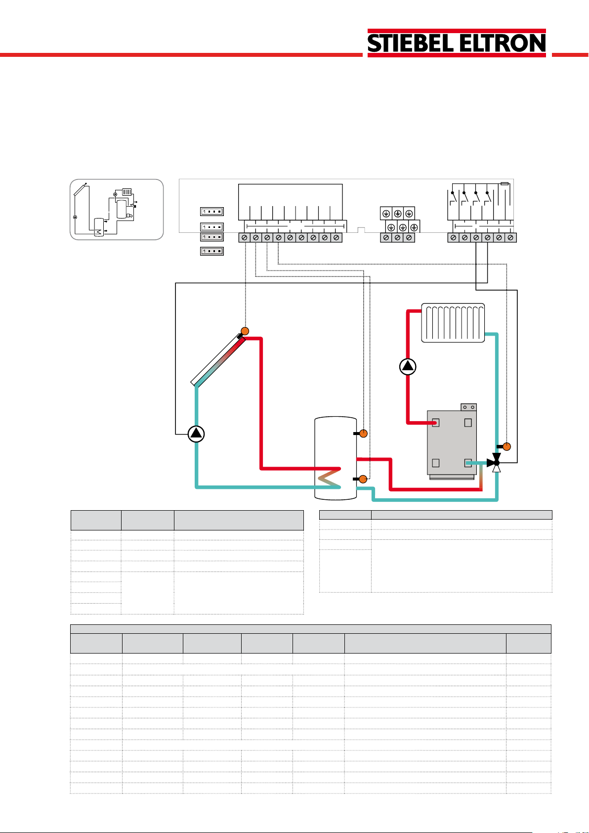
System 9
Solar system with 1 tank and heating circuit return preheating
The controller calculates the temperature difference between collector sensor S1 and tank sensor S2. If the difference is larger than or identical to the adjusted switch-on
temperature difference, the pump (R1) will be switched on
and the tank will be loaded until the switch-off temperature
difference or the maximum tank temperature is reached.
With another temperature differential function (S3/S4)
heating circuit return preheating (heating circuit backup) is
possible via a valve (R2).
R1
VFS
RPS
Te mp. Sensor
Pt1000
S1
S2
S3
S1
S4
S5
GND
out in
PWM 1
PWM 2
L
V40
VBus
R4
L'
R3
R2
R1
N
S3
S4
S2
R2
Sensor/Terminal
S1 TCOL Temperature collector
S2 TSTB Temperature tank bottom
S3 TSTR Temp. tank return preheating
S4 TRET Temperature - return
S5 Optional sensor for measurement
VFS
Designation Description
purposes or options
Relay Description
R1 Solar pump
R2 Return preheating
R3 optional:
R4
Thermal disinfection
Booster pump
Parallel relay
Heat dump
RPS
V40
Adjustment channels
Channel Sub channel 1 Sub channel 2 Factory
Change to Description Page
setting
ARR 1 9 System
78
LOAD > Loading
DT O 12 °R Switch-on temperature difference 78
DT F 8 °R Switch-off temperature difference 78
DT S 20 °R Set temperature difference 78
RIS 4 °R Rise 78
S MAX 140 °F Tank maximum limitation 78
SMAXS 2 Sensor tank max 79
COL > Collector
CEM 270 °F Collector emergency temperature 80
OCCO** OFF Option collector cooling 80
CMAX 230 °F Maximum collector temperature 80
© Stiebel 11091_SOM_9s.monus.indd
OCMI OFF Option collector minimum limitation 80
25 |
Page 26

SOM 9s
Adjustment channels
Channel Sub channel 1 Sub channel 2 Factory
CMIN 50 °F Minimum collector temperature 80
OTCO OFF Option evacuated tube collector function 81
TCST 07:00 Evacuated tube collector starting time 81
TCEN 19:00 Evacuated tube collector ending time 81
TCRU 30 s Evacuated tube collector runtime 81
TCIN 30 min Evacuated tube collector standstill interval 81
OCFR OFF Option collector frost protection 82
CFR O 40 °F Antifreeze temperature collector on 82
CFR F 42 °F Antifreeze temperature collector off 82
LLOGI > Loading logic
ODB > OFF Drainback option 84
OOVRU* OFF Overrun option 84
COOL > Cooling functions
OSYC** OFF System cooling 85
OSTC OFF Tank cooling 85
OHDP** OFF Heat dump 85
DT3 > Solid fuel boiler
DT3O 12 °R Switch-on difference 86
DT3F 8 °R Switch-off difference 86
S2DT3 3 Reference sensor heat source 87
PUMP > Pump speed
PUMP1 OnOF Speed variant pump 1 79
PUMP2 OnOF Speed variant pump 2 79
PUMP3 OnOF Speed variant pump 3 79
MAN > Manual mode
MAN1 Auto Manual mode 1 88
MAN2 Auto Manual mode 2 88
MAN3 Auto Manual mode 3 88
MAN4 Auto Manual mode 4 88
BLPR >
OTDIS > OFF Thermal disinfection option 89
OPARR > OFF Parallel relay option 90
OHQM > OFF Energy metering option 90
GFDS > OFF Registration Grundfos sensors 90
PRS* > OFF Pressure monitoring option 92
DATE> OFF Enter date 92
LANG > En Language 93
UNIT > °F Unit 92
OSDC > SD card option 93
CODE 0000 User code 96
RESET OFF Factory setting
* This channel is only available if the Grundfos sensors have been registered in the GFDS channel.
** are blocked against each other
setting
OFF Blocking protection 88
Change to Description Page
| 26
© Stiebel 11091_SOM_9s.monus.indd
Page 27
SOM 9s
R4
R2
R1
S4
S3
S2
S1
Temp.Sensor
Pt1000
L
R3
R2
R1
GND
S1
S2
S3
S4
S5
VBus
PWM 1
PWM 2
N
R4
V40
L'
VFS
RPS
out in
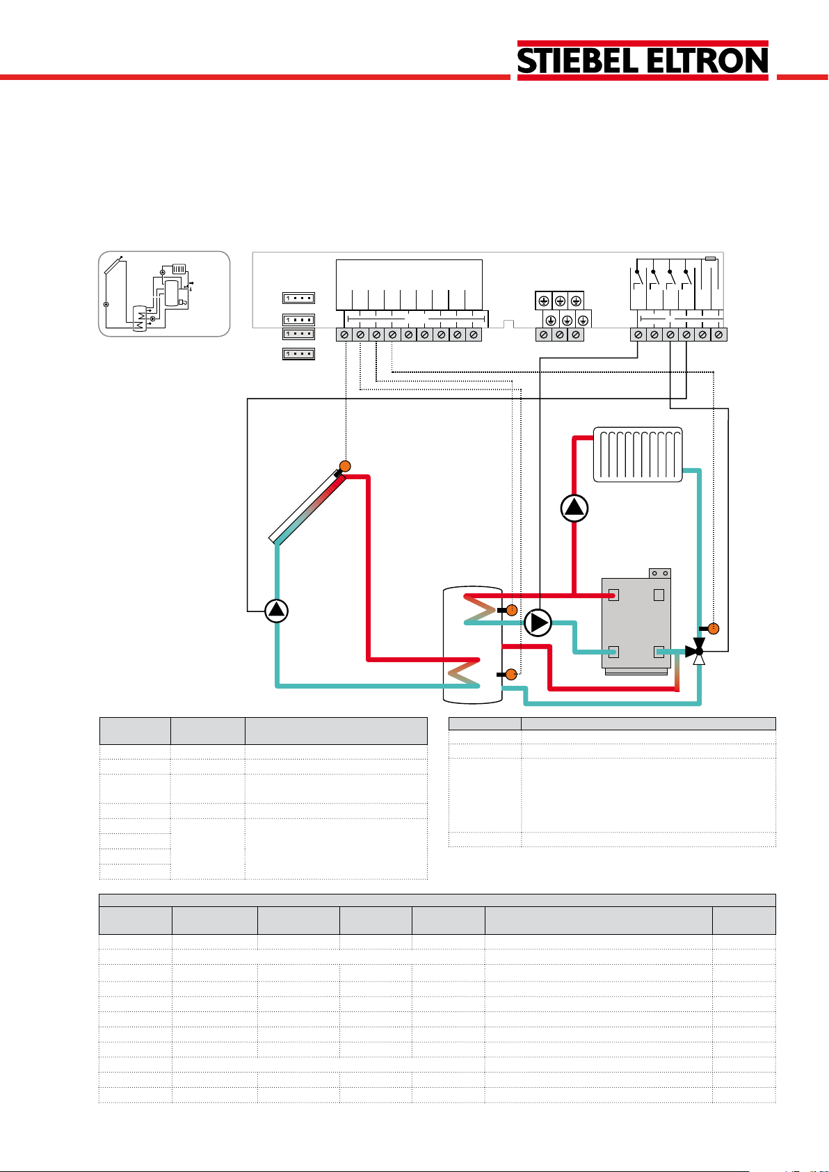
System 10
Solarsystemwith1tank,heatingcircuitreturnpreheatingandthermostaticbackupheating
The controller calculates the temperature difference between collector sensor S1 and tank sensor S2. If the difference is larger than or identical to the adjusted switch-on
temperature difference, the pump (R1) will be switched on
and the tank will be loaded until the switch-off temperature
difference or the maximum tank temperature is reached.
With another temperature differential function (S3/S4)
heating circuit backup (heating circuit return preheating) is
possible via a valve (R2). With a thermostat function (S3)
domestic hot water backup heating (R4) can be carried out.
Sensor/Terminal
S1 TCOL Temperature collector
S2 TSTB Temperature tank bottom
S3 TSTT/TSTR Temperature tank top/
S4 TRET Temperature - return
S5 Optional sensor for measurement
VFS
Designation Description
Temp. tank return preheating
purposes or options
Relay Description
R1 Solar pump
R2 Return preheating
R3 optional:
Thermal disinfection
Booster pump
Parallel relay
Heat dump
R4 Backup heating/tank loading pump
RPS
V40
Adjustment channels
Channel Sub channel 1 Sub channel 2 Factory
setting
Change to Description Page
ARR 1 10 System 78
LOAD > Loading
DT O 12 °R Switch-on temperature difference 78
DT F 8 °R Switch-off temperature difference 78
DT S 20 °R Set temperature difference 78
RIS 4 °R Rise 78
S MAX 140 °F Tank maximum limitation 78
SMAXS 2 Sensor tank max 79
COL > Collector
CEM 270 °F Collector emergency temperature 80
OCCO** OFF Option collector cooling 80
© Stiebel 11091_SOM_9s.monus.indd
27 |
Page 28

SOM 9s
Adjustment channels
Channel Sub channel 1 Sub channel 2 Factory
CMAX 230 °F Maximum collector temperature 80
OCMI OFF Option collector minimum limitation 80
CMIN 50 °F Minimum collector temperature 80
OTCO OFF Option evacuated tube collector function 81
TCST 07:00 Evacuated tube collector starting time 81
TCEN 19:00 Evacuated tube collector ending time 81
TCRU 30 s Evacuated tube collector runtime 81
TCIN 30 min Evacuated tube collector standstill interval 81
OCFR OFF Option collector frost protection 82
CFR O 40 °F Antifreeze temperature collector on 82
CFR F 42 °F Antifreeze temperature collector off 82
LLOGI > Loading logic
ODB > OFF Drainback option 84
OOVRU* OFF Overrun option 84
COOL > Cooling functions
OSYC** OFF System cooling 85
OSTC OFF Tank cooling 85
OHDP** OFF Heat dump 85
DT3 > Return preheating
DT3O 12 °R Switch-on difference 86
DT3F 8 °R Switch-off difference 86
S2DT3 3 Reference sensor heat source 87
AH > Backup heating option
AH O 110 °F Backup heating switch-on temperature 87
AH F 120 °F Backup heating switch-off temperature 87
t1O 06:00 Switch-on time 1 88
t1F 22:00 Switch-off time 1 88
t2O 00:00 Switch-on time 2 88
t2F 00:00 Switch-off time 2 88
t3O 00:00 Switch-on time 3 88
t3F 00:00 Switch-off time 3 88
PUMP > Pump speed
PUMP1 OnOF Speed variant pump 1 79
PUMP2 OnOF Speed variant pump 2 79
PUMP3 OnOF Speed variant pump 3 79
MAN > Manual mode
MAN1 Auto Manual mode 1 88
MAN2 Auto Manual mode 2 88
MAN3 Auto Manual mode 3 88
MAN4 Auto Manual mode 4 88
BLPR >
OTDIS > OFF Thermal disinfection option 89
OPARR > OFF Parallel relay option 90
OHQM > OFF Energy metering option 90
GFDS > OFF Registration Grundfos sensors 90
PRS* > OFF Pressure monitoring option 92
DATE> Enter date 92
LANG > En Language 93
UNIT > °F Unit 92
OSDC > SD card option 93
CODE 0000 User code 96
RESET OFF Factory setting
* This channel is only available if the Grundfos sensors have been registered in the GFDS channel.
** are blocked against each other
setting
OFF Blocking protection 88
Change to Description Page
| 28
© Stiebel 11091_SOM_9s.monus.indd
Page 29
SOM 9s
System 11
Solar system with vertical tank loading and heat exchange control
The controller compares the temperature at sensor S1 to
the temperatures at sensors S2 and S3. If the measured
temperature differences are higher than the adjusted switchon temperature differences, the pump (R1) will be activated
and the corresponding tank zone will be loaded up to the
adjusted maximum temperature via the valve (R3).
The priority logic effects prior loading of the upper zone
of the tank.
Heat exchange control to an existent tank via an additional
pump (R2) can be carried out with another temperature
differential function (S3 heat source/S4 heat sink).
Te mp.Sensor
S1
Pt1000
S2
VFS
RPS
S1
R3
R1
Note: 3-port valve normally open - tank bottom
out in
L
S3
S4
S5
PWM 1
PWM 2
V40
GND
VBus
R4
L'
R1
R3
R2
N
S3
R2
S4
S2
Sensor/Terminal
S1 TCOL Temperature collector
S2 TST1B Temperature tank 1 bottom
S3 TSTT Temperature tank 1 top
S4 TST2B Temperature tank 2 bottom
S5 Optional sensor for measurement
VFS
Designation Description
purposes or options
Relay Description
R1 Solar pump
R2 Heat exchange pump
R3 3-port valve tank top/bottom
R4 optional:
Thermal disinfection
Parallel relay
Heat dump
RPS
V40
Adjustment channels
Channel Sub channel 1 Sub channel 2 Factory
Change to Description Page
setting
ARR 1 11 System 78
LOAD1 > Loading 1
DT1O 12 °R Switch-on temperature difference 1 78
DT1F 8 °R Switch-off temperature difference 1 78
DT1S 20 °R Set temperature difference 1 78
RIS1 4 °R Rise 1 78
S1MAX 140 °F Tank maximum limitation 1 78
SMXS1 2 Sensor tank max 1 79
LOAD2 > Loading 2
DT2O 12 °R Switch-on temperature difference 2 78
DT2F 8 °R Switch-off temperature difference 2 78
DT2S 20 °R Set temperature difference 2 78
RIS2 4 °R Rise 2 78
© Stiebel 11091_SOM_9s.monus.indd
S2MAX 140 °F Tank maximum limitation 2 78
29 |
Page 30

SOM 9s
Adjustment channels
Channel Sub channel 1 Sub channel 2 Factory
setting
LST2 ON Loading tank 2 79
COL > Collector
CEM 270 °F Collector emergency temperature 80
OCCO** OFF Option collector cooling 80
CMAX 230 °F Maximum collector temperature 80
OCMI OFF Option collector minimum limitation 80
CMIN 50 °F Minimum collector temperature 80
OTCO OFF Option evacuated tube collector function 81
TCST 07:00 Evacuated tube collector starting time 81
TCEN 19:00 Evacuated tube collector ending time 81
TCRU 30 s Evacuated tube collector runtime 81
TCIN 30 min Evacuated tube collector standstill interval 81
OCFR OFF Option collector frost protection 82
CFR O 40 °F Antifreeze temperature collector on 82
CFR F 42 °F Antifreeze temperature collector off 82
LLOGI > Loading logic
PRIO Priority logic 82
PRIO 2 Priority logic 82
OSTS OFF Tank set option 83
TST1 120 °F Set tank temperature tank 1 83
TST2 120 °F Set tank temperature tank 2 83
tLB 2 min Loading break time 82
tRUN 15 min Circulation runtime 82
PSPEE OFF Pause speed option 83
PDELA OFF Pump delay option 83
OOVRU* OFF Overrun option 84
COOL > Cooling functions
OSYC** OFF System cooling 85
OSTC OFF Tank cooling 85
OHDP** OFF Heat dump 85
DT3 > Heat exchange
DT3O 12 °R Switch-on difference 86
DT3F 8 °R Switch-off difference 86
DT3S 20 °R Set difference 86
RIS3 4 °R Rise 86
MAX3O 140 °F Switch-on temperature (maximum limitation) 86
MAX3F 136 °F Switch-off temperature (maximum limitation) 86
MIN3O 40 °F Switch-on temperature (minimum limitation) 86
MIN3F 50 °F Switch-off temperature (minimum limitation) 86
S2DT3 4 Reference sensor heat sink 87
PUMP > Pump speed
PUMP1 OnOF Speed variant pump 1 79
PUMP2 OnOF Speed variant pump 2 79
PUMP3 OnOF Speed variant pump 3 79
MAN > Manual mode
MAN1 Auto Manual mode 1 88
MAN2 Auto Manual mode 2 88
MAN3 Auto Manual mode 3 88
MAN4 Auto Manual mode 4 88
BLPR > OFF Blocking protection 88
OTDIS > OFF Thermal disinfection option 89
OPARR > OFF Parallel relay option 90
OHQM > OFF Energy metering option 90
GFDS > OFF Registration Grundfos sensors 90
PRS* > OFF Pressure monitoring option 92
DATE> Enter date 92
LANG > En Language 93
UNIT > °F Unit 92
OSDC > SD card option 93
CODE 0000 User code 96
RESET OFF Factory setting
* This channel is only available if the Grundfos sensors have been registered in the GFDS channel.
** are blocked against each other
| 30
Change to Description Page
© Stiebel 11091_SOM_9s.monus.indd
Page 31

SOM 9s
R3
R1
S3
S2
S1
Temp. Sensor
Pt1000
L
R3
R2
R1
GND
S1
S2
S3
S4
S5
VBus
PWM 1
PWM 2
N
R4
V40
L'
VFS
RPS
out in
System 12
Solar system with vertical tank loading and thermostatic backup heating
The controller compares the temperature at sensor S1 to
the temperatures at sensors S2 and S3. If the measured
temperature differences are higher than the adjusted switchon temperature differences, the pump (R1) will be activated
and the corresponding tank zone will be loaded up to the
adjusted maximum temperature via the valve (R3). The priority logic effects prior loading of the upper zone of the tank.
Domestic hot water backup heating (R4) can be carried out
with a thermostat function (S3).
Note: 3-port valve normally open - tank bottom
Sensor/Terminal
S1 TCOL Temperature collector
S2 TSTB Temperature tank bottom
S3 TSTT Temperature tank top
S4 Optional sensor for measurement
S5
VFS
RPS
V40
Adjustment channels
Channel Sub channel 1 Sub channel 2 Factory
ARR 1 12 System 78
LOAD1 > Loading 1
LOAD2 > Loading 2
© Stiebel 11091_SOM_9s.monus.indd
Designation Description
Relay Description
R1 Solar pump
R2 optional:
Thermal disinfection
purposes or options
R3 3-port valve tank top/bottom
Parallel relay
Heat dump
R4 Backup heating/tank loading pump
Change to Description Page
setting
DT1O 12 °R Switch-on temperature difference 1 78
DT1F 8 °R Switch-off temperature difference 1 78
DT1S 20 °R Set temperature difference 1 78
RIS1 4 °R Rise 1 78
S1MAX 60 Tank maximum limitation 1 78
SMXS1 2 Sensor tank max 1 79
DT2O 12 °R Switch-on temperature difference 2 78
DT2F 8 °R Switch-off temperature difference 2 78
DT2S 20 °R Set temperature difference 2 78
RIS2 4 °R Rise 2 78
31 |
Page 32

SOM 9s
Adjustment channels
Channel Sub channel 1 Sub channel 2 Factory
setting
S2MAX 140 °F Tank maximum limitation 2 78
LST2 ON Loading tank 2 79
COL > Collector
CEM 270 °F Collector emergency temperature 80
OCCO** OFF Option collector cooling 80
CMAX 230 °F Maximum collector temperature 80
OCMI OFF Option collector minimum limitation 80
CMIN 50 °F Minimum collector temperature 80
OTCO OFF Option evacuated tube collector function 81
TCST 07:00 Evacuated tube collector starting time 81
TCEN 19:00 Evacuated tube collector ending time 81
TCRU 30 s Evacuated tube collector runtime 81
TCIN 30 min Evacuated tube collector standstill interval 81
OCFR OFF Option collector frost protection 82
CFR O 40 °F Antifreeze temperature collector on 82
CFR F 42 °F Antifreeze temperature collector off 82
LLOGI > Loading logic
PRIO Priority logic 82
PRIO 2 Priority logic 82
OSTS OFF Tank set option 83
TST1 120 °F Set tank temperature tank 1 83
TST2 120 °F Set tank temperature tank 2 83
tLB 2 min Loading break time 82
tRUN 15 min Circulation runtime 82
PSPEE OFF Pause speed option 83
PDELA OFF Pump delay option 83
OOVRU* OFF Overrun option 84
COOL > Cooling functions
OSYC** OFF System cooling 85
OSTC OFF Tank cooling 85
OHDP** OFF Heat dump 85
AH > Backup heating option
AH O 110 °F Backup heating switch-on temperature 87
AH F 120 °F Backup heating switch-off temperature 87
t1O 06:00 Switch-on time 1 88
t1F 22:00 Switch-off time 1 88
t2O 00:00 Switch-on time 2 88
t2F 00:00 Switch-off time 2 88
t3O 00:00 Switch-on time 3 88
t3F 00:00 Switch-off time 3 88
PUMP > Pump speed
PUMP1 OnOF Speed variant pump 1 79
PUMP2 OnOF Speed variant pump 2 79
PUMP3 OnOF Speed variant pump 3 79
MAN > Manual mode
MAN1 Auto Manual mode 1 88
MAN2 Auto Manual mode 2 88
MAN3 Auto Manual mode 3 88
MAN4 Auto Manual mode 4 88
BLPR > OFF Blocking protection 88
OTDIS > OFF Thermal disinfection option 89
OPARR > OFF Parallel relay option 90
OHQM > OFF Energy metering option 90
GFDS > OFF Registration Grundfos sensors 90
PRS* > OFF Pressure monitoring option 92
DATE> Enter date 92
LANG > En Language 93
UNIT > °F Unit 92
OSDC > SD card option 93
CODE 0000 User code 96
RESET OFF Factory setting
* This channel is only available if the Grundfos sensors have been registered in the GFDS channel.
** are blocked against each other
| 32
Change to Description Page
© Stiebel 11091_SOM_9s.monus.indd
Page 33

SOM 9s
R4
R3
R1
S4
S3
S2
S1
Temp. Sensor
Pt1000
L
R3
R2
R1
GND
S1
S2
S3
S4
S5
VBus
PWM 1
PWM 2
N
R4
V40
L'
VFS
RPS
out in
System 13
Solar system with vertical tank loading and backup heating with solid fuel boiler
The controller compares the temperature at sensor S1 to
the temperatures at sensors S2 and S3. If the measured temperature differences are higher than the adjusted switch-on
temperature differences, the pump (R1) will be activated and
the corresponding tank zone will be loaded up to the adju-
sted maximum temperature via the valve (R4). The priority
logic effects prior loading of the upper zone of the tank.
With another temperature differential function (S4/S3),
backup heating of the tank can be carried out with a solid
fuel boiler (R3).
Note: 3-port valve normally open - tank bottom
Sensor/Terminal
S1 TCOL Temperature collector
S2 TSTB Temperature tank bottom
S3 TSTT Temperature tank top
S4 TSFB Temperature solid fuel boiler
S5 Optional sensor for measurement
VFS
RPS
V40
Adjustment channels
Channel Sub channel 1 Sub channel 2 Factory
ARR 1 13 System 78
LOAD1 > Loading 1
LOAD2 > Loading 2
© Stiebel 11091_SOM_9s.monus.indd
Designation Description
Relay Description
R1 Solar pump
R2 optional:
Thermal disinfection
Parallel relay
Heat dump
R3 Loading pump/solid fuel boiler
purposes or options
R4 3-port valve tank top/bottom
Change to Description Page
setting
DT1O 12 °R Switch-on temperature difference 1 78
DT1F 8 °R Switch-off temperature difference 1 78
DT1S 20 °R Set temperature difference 1 78
RIS1 4 °R Rise 1 78
S1MAX 140 °F Tank maximum limitation 1 78
SMXS1 2 Sensor tank max 1 79
DT2O 12 °R Switch-on temperature difference 2 78
DT2F 8 °R Switch-off temperature difference 2 78
DT2S 20 °R Set temperature difference 2 78
RIS2 4 °R Rise 2 78
S2MAX 140 °F Tank maximum limitation 2 78
33 |
Page 34

SOM 9s
Adjustment channels
Channel Sub channel 1 Sub channel 2 Factory
setting
LST2 ON Loading tank 2 79
COL > Collector
CEM 270 °F Collector emergency temperature 80
OCCO** OFF Option collector cooling 80
CMAX 230 °F Maximum collector temperature 80
OCMI OFF Option collector minimum limitation 80
CMIN 50 °F Minimum collector temperature 80
OTCO OFF Option evacuated tube collector function 81
TCST 07:00 Evacuated tube collector starting time 81
TCEN 19:00 Evacuated tube collector ending time 81
TCRU 30 s Evacuated tube collector runtime 81
TCIN 30 min Evacuated tube collector standstill interval 81
OCFR OFF Option collector frost protection 82
CFR O 40 °F Antifreeze temperature collector on 82
CFR F 42 °F Antifreeze temperature collector off 82
LLOGI > Loading logic
PRIO Priority logic 82
PRIO 2 Priority logic 82
OSTS OFF Tank set option 83
TST1 120 °F Set tank temperature tank 1 83
TST2 120 °F Set tank temperature tank 2 83
tLB 2 min Loading break time 82
tRUN 15 min Circulation runtime 82
PSPEE OFF Pause speed option 83
PDELA OFF Pump delay option 83
OOVRU* OFF Overrun option 84
COOL > Cooling functions
OSYC** OFF System cooling 85
OSTC OFF Tank cooling 85
OHDP** OFF Heat dump 85
DT3 > Solid fuel boiler
DT3O 12 °R Switch-on difference 86
DT3F 8 °R Switch-off difference 86
DT3S 20 °R Set difference 86
RIS3 4 °R Rise 86
MAX3O 140 °F Switch-on temperature (maximum limitation) 86
MAX3F 136 °F Switch-off temperature (maximum limitation) 86
MIN3O 140 °F Switch-on temperature (minimum limitation) 86
MIN3F 149 °F Switch-off temperature (minimum limitation) 86
S2DT3 3 Reference sensor heat sink 87
PUMP > Pump speed
PUMP1 OnOF Speed variant pump 1 79
PUMP2 OnOF Speed variant pump 2 79
PUMP3 OnOF Speed variant pump 3 79
MAN > Manual mode
MAN1 Auto Manual mode 1 88
MAN2 Auto Manual mode 2 88
MAN3 Auto Manual mode 3 88
MAN4 Auto Manual mode 4 88
BLPR > OFF Blocking protection 88
OTDIS > OFF Thermal disinfection option 89
OPARR > OFF Parallel relay option 90
OHQM > OFF Energy metering option 90
GFDS > OFF Registration Grundfos sensors 90
PRS* > OFF Pressure monitoring option 92
DATE> Enter date 92
LANG > En Language 93
UNIT > °F Unit 92
OSDC > SD card option 93
CODE 0000 User code 96
RESET OFF Factory setting
* This channel is only available if the Grundfos sensors have been registered in the GFDS channel.
** are blocked against each other
| 34
Change to Description Page
© Stiebel 11091_SOM_9s.monus.indd
Page 35

SOM 9s
R3
R2
R1
S4
S3
S2
S1
Temp. Sensor
Pt1000
L
R3
R2
R1
GND
S1
S2
S3
S4
S5
VBus
PWM 1
PWM 2
N
R4
V40
L'
VFS
RPS
out in
System 14
Solar system with vertical tank loading and return preheating
The controller compares the temperature at sensor S1 to
the temperatures at sensors S2 and S3. If the measured
temperature differences are higher than the adjusted switchon temperature differences, the pump (R1) will be activated
and the corresponding tank zone will be loaded up to the
adjusted maximum temperature via the valve (R3). The priority logic effects prior loading of the upper zone of the tank.
With another temperature differential function (S3-heat
source/S4-heat sink) heating circuit return preheating (heating circuit backup) is possible via another valve (R2).
Note: 3-port valve normally open - tank bottom
Sensor/Terminal
S1 TCOL Temperature collector
S2 TSTB Temperature tank bottom
S3 TSTT/TSTR Temperature tank top/
S4 TRET Temperature return
S5 Optional sensor for measurement
VFS
RPS
V40
Adjustment channels
Channel Sub channel 1 Sub channel 2 Factory
ARR 1 14 System 78
LOAD1 > Loading 1
LOAD2 > Loading 2
© Stiebel 11091_SOM_9s.monus.indd
Designation Description
Relay Description
R1 Solar pump
R2 Return preheating
R3 3-port valve tank top/bottom
R4 optional:
Thermal disinfection
Parallel relay
Heat dump
Temp. tank return preheating
purposes or options
Change to Description Page
setting
DT1O 12 °R Switch-on temperature difference 1 78
DT1F 8 °R Switch-off temperature difference 1 78
DT1S 20 °R Set temperature difference 1 78
RIS1 4 °R Rise 1 78
S1MAX 140 °F Tank maximum limitation 1 78
SMXS1 2 Sensor tank max 1 79
DT2O 12 °R Switch-on temperature difference 2 78
DT2F 8 °R Switch-off temperature difference 2 78
DT2S 20 °R Set temperature difference 2 78
RIS2 4 °R Rise 2 78
35 |
Page 36

SOM 9s
Adjustment channels
Channel Sub channel 1 Sub channel 2 Factory
S2MAX 140 °F Tank maximum limitation 2 78
LST2 ON Loading tank 2 79
COL > Collector
CEM 270 °F Collector emergency temperature 80
OCCO** OFF Option collector cooling 80
CMAX 230 °F Maximum collector temperature 80
OCMI OFF Option collector minimum limitation 80
CMIN 50 °F Minimum collector temperature 80
OTCO OFF Option evacuated evacuated tube collector function 81
TCST 07:00 Evacuated evacuated tube collector starting time 81
TCEN 19:00 Evacuated evacuated tube collector ending time 81
TCRU 30 s Evacuated tube collector runtime 81
TCIN 30 min Evacuated evacuated tube collector standstill interval 81
OCFR OFF Option collector frost protection 82
CFR O 40 °F Antifreeze temperature collector on 82
CFR F 42 °F Antifreeze temperature collector off 82
LLOGI > Loading logic
PRIO Priority logic 82
PRIO 2 Priority logic 82
OSTS OFF Tank set option 83
TST1 120 °F Set tank temperature tank 1 83
TST2 120 °F Set tank temperature tank 2 83
tLB 2 min Loading break time 82
tRUN 15 min Circulation runtime 82
PSPEE OFF Pause speed option 83
PDELA OFF Pump delay option 83
OOVRU* OFF Overrun option 84
COOL > Cooling functions
OSYC** OFF System cooling 85
OSTC OFF Tank cooling 85
OHDP** OFF Heat dump 85
DT3 > Return preheating
DT3O 12 °R Switch-on difference 86
DT3F 8 °R Switch-off difference 86
S2DT3 3 Reference sensor heat source 87
PUMP > Pump speed
PUMP1 OnOF Speed variant pump 1 79
PUMP2 OnOF Speed variant pump 2 79
PUMP3 OnOF Speed variant pump 3 79
MAN > Manual mode
MAN1 Auto Manual mode 1 88
MAN2 Auto Manual mode 2 88
MAN3 Auto Manual mode 3 88
MAN4 Auto Manual mode 4 88
BLPR >
OTDIS > OFF Thermal disinfection option 89
OPARR > OFF Parallel relay option 90
OHQM > OFF Energy metering option 90
GFDS > OFF Registration Grundfos sensors 90
PRS* > OFF Pressure monitoring option 92
DATE> Enter date 92
LANG > En Language 93
UNIT > °F Unit 92
OSDC > SD card option 93
CODE 0000 User code 96
RESET OFF Factory setting
* This channel is only available if the Grundfos sensors have been registered in the GFDS channel.
** are blocked against each other
setting
OFF Blocking protection 88
| 36
Change to Description Page
© Stiebel 11091_SOM_9s.monus.indd
Page 37

SOM 9s
System 15
Solar system with vertical tank loading and backup heating via heating backup
The controller compares the temperature at sensor S1 to
the temperatures at sensors S2 and S3. If the measured
temperature differences are higher than the adjusted switchon temperature differences, the pump (R1) will be activated
and the corresponding tank zone will be loaded up to the
adjusted maximum temperature at most via the valve (R3).
The priority logic effects prior loading of the upper zone
of the tank.
With another temperature differential function (S3-heat
source/S4-heat sink) heating circuit return preheating (heating circuit backup) is possible via another valve (R2). Domestic hot water backup heating (R4) can be carried out
with a thermostat function (S3).
R1
VFS
RPS
Te mp. Sensor
Pt1000
S1
S2
S3
S1
R3
S4
S5
GND
out in
PWM 1
PWM 2
L
V40
VBus
S3
R4
R4
L'
R3
R2
R1
N
S4
S2
R2
Note: 3-port valve normally open - tank bottom
Sensor/Ter-
Designation Description
minal
S1 TCOL Temperature collector
S2 TSTB Temperature tank bottom
S3 TSTT/TSTR Temperature tank top/
Temp. tank return preheating
S4 TRET Temperature return
S5 Optional sensor for measurement
VFS
purposes or options
RPS
V40
Adjustment channels
Channel Sub channel 1 Sub channel 2 Factory
setting
ARR 1 15 System 78
LOAD1 > Loading 1
DT1O 12 °R Switch-on temperature difference 1 78
DT1F 8 °R Switch-off temperature difference 1 78
DT1S 20 °R Set temperature difference 1 78
RIS1 4 °R Rise 1 78
S1MAX 140 °F Tank maximum limitation 1 78
SMXS1 2 Sensor tank max 1 79
© Stiebel 11091_SOM_9s.monus.indd
Relay Description
R1 Solar pump
R2 Return preheating
R3 3-port valve tank top/bottom
R4 Backup heating/tank loading pump
Change to Description Page
37 |
Page 38

SOM 9s
Adjustment channels
Channel Sub channel 1 Sub channel 2 Factory
setting
LOAD2 > Loading 2
DT2O 12 °R Switch-on temperature difference 2 78
DT2F 8 °R Switch-off temperature difference 2 78
DT2S 20 °R Set temperature difference 2 78
RIS2 4 °R Rise 2 78
S2MAX 140 °F Tank maximum limitation 2 78
LST2 ON Loading tank 2 79
COL > Collector
CEM 270 °F Collector emergency temperature 80
OCCO** OFF Option collector cooling 80
CMAX 230 °F Maximum collector temperature 80
OCMI OFF Option collector minimum limitation 80
CMIN 50 °F Minimum collector temperature 80
OTCO OFF Option evacuated evacuated tube collector
TCST 07:00 Evacuated evacuated tube collector starting time 81
TCEN 19:00 Evacuated evacuated tube collector ending time 81
TCRU 30 s Evacuated evacuated tube collector runtime 81
TCIN 30 min Evacuated tube collector standstill interval 81
OCFR OFF Option collector frost protection 82
CFR O 40 °F Antifreeze temperature collector on 82
CFR F 42 °F Antifreeze temperature collector off 82
LLOGI > Loading logic
PRIO Priority logic 82
PRIO 2 Priority logic 82
OSTS OFF Tank set option 83
TST1 120 °F Set tank temperature tank 1 83
TST2 120 °F Set tank temperature tank 2 83
tLB 2 min Loading break time 82
tRUN 15 min Circulation runtime 82
PSPEE OFF Pause speed option 83
PDELA OFF Pump delay option 83
OOVRU* OFF Overrun option 84
COOL > Cooling functions
OSYC** OFF System cooling 85
OSTC OFF Tank cooling 85
OHDP** OFF Heat dump 85
DT3 > Return preheating
DT3O 12 °R Switch-on difference 86
DT3F 8 °R Switch-off difference 86
S2DT3 3 Reference sensor heat source 87
AH > Backup heating option
AH O 110 °F Backup heating switch-on temperature 87
AH F 120 °F Backup heating switch-off temperature 87
t1O 06:00 Switch-on time 1 88
t1F 22:00 Switch-off time 1 88
t2O 00:00 Switch-on time 2 88
t2F 00:00 Switch-off time 2 88
t3O 00:00 Switch-on time 3 88
t3F 00:00 Switch-off time 3 88
PUMP > Pump speed
PUMP1 OnOF Speed variant pump 1 79
PUMP2 OnOF Speed variant pump 2 79
PUMP3 OnOF Speed variant pump 3 79
MAN > Manual mode
MAN1 Auto Manual mode 1 88
MAN2 Auto Manual mode 2 88
MAN3 Auto Manual mode 3 88
MAN4 Auto Manual mode 4 88
BLPR > OFF Blocking protection 88
OTDIS > OFF Thermal disinfection option 89
OPARR> OFF Parallel relay option 90
| 38
Change to Description Page
function
81
© Stiebel 11091_SOM_9s.monus.indd
Page 39

SOM 9s
Adjustment channels
Channel Sub channel 1 Sub channel 2 Factory
setting
OHQM > OFF Energy metering option 90
GFDS > OFF Registration Grundfos sensors 90
PRS* > OFF Pressure monitoring option 92
DATE> Enter date 92
LANG > En Language 93
UNIT > °F Unit 92
OSDC > SD card option 93
CODE 0000 User code 96
RESET OFF Factory setting
* This channel is only available if the Grundfos sensors have been registered in the GFDS channel.
** are blocked against each other
Change to Description Page
© Stiebel 11091_SOM_9s.monus.indd
39 |
Page 40

SOM 9s
R2
R3
R1
S4
S3
S2
S1
Temp. Sensor
Pt1000
L
R3
R2
R1
GND
S1
S2
S3
S4
S5
VBus
PWM 1
PWM 2
N
R4
V40
L'
VFS
RPS
out in
System 16
2-tank solar system with valve logic and heat exchange control
The controller compares the temperature at sensor S1 to
the temperatures at sensors S2 and S4. If the measured
temperature differences are higher than the adjusted switchon temperature differences, the pump (R1) will be activated
and the corresponding tank zone will be loaded up to the
adjusted maximum temperature via the valve (R3). Tank 1
is loaded with priority. Heat exchange from tank 1 to tank
2 (R2) is possible with another temperature differential
function (S3-heat source/S4-heat sink).
Note: 3-port valve normally open
- tank 1 (S2)
Sensor/Terminal
S1 TCOL Temperature collector
S2 TST1B Temperature tank 1 bottom
S3 TSTT Temperature tank 1 top
S4 TST2B Temperature tank 2 bottom
S5 Optional sensor for measurement
VFS
RPS
V40
Adjustment channels
Channel Sub channel 1 Sub channel 2 Factory
ARR 1 16 System 78
LOAD1 > Loading 1
LOAD2 > Loading 2
| 40
Designation Description
Relay Description
R1 Solar pump
R2 Heat exchange pump
R3 3-port valve tank 1 / 2
R4 optional:
Thermal disinfection
purposes or options
Parallel relay
Heat dump
Change to Description Page
setting
DT1O 12 °R Switch-on temperature difference 1 78
DT1F 8 °R Switch-off temperature difference 1 78
DT1S 20 °R Set temperature difference 1 78
RIS1 4 °R Rise 1 78
S1MAX 140 °F Tank maximum limitation 1 78
SMXS1 2 Sensor tank max 1 79
DT2O 12 °R Switch-on temperature difference 2 78
DT2F 8 °R Switch-off temperature difference 2 78
DT2S 20 °R Set temperature difference 2 78
RIS2 4 °R rise 2 78
S2MAX 140 °F Tank maximum limitation 2 78
SMXS2 4 Sensor tank max 2 79
LST2 ON Loading tank 2 79
© Stiebel 11091_SOM_9s.monus.indd
Page 41

SOM 9s
Adjustment channels
Channel Sub channel 1 Sub channel 2 Factory
COL > Collector
CEM 270 °F Collector emergency temperature 80
OCCO** OFF Option collector cooling 80
CMAX 230 °F Maximum collector temperature 80
OCMI OFF Option collector minimum limitation 80
CMIN 50 °F Minimum collector temperature 80
OTCO OFF Option evacuated tube collector function 81
TCST 07:00 Evacuated tube collector starting time 81
TCEN 19:00 Evacuated tube collector ending time 81
TCRU 30 s Evacuated tube collector runtime 81
TCIN 30 min Evacuated tube collector standstill interval 81
OCFR OFF Option collector frost protection 82
CFR O 40 °F Antifreeze temperature collector on 82
CFR F 42 °F Antifreeze temperature collector off 82
FRPST 1 Antifreeze tank selection 82
LLOGI > Loading logic
PRIO Priority logic 82
PRIO 1 Priority logic 82
OSTS OFF Tank set option 83
TST1 120 °F Set tank temperature tank 1 83
TST2 120 °F Set tank temperature tank 2 83
tLB 2 min Loading break time 82
tRUN 15 min Circulation runtime 82
PSPEE OFF Pause speed option 83
PDELA OFF Pump delay option 83
OOVRU* OFF Overrun option 84
COOL > Cooling functions
OSYC** OFF System cooling 85
OSTC OFF Tank cooling 85
OHDP** OFF Heat dump 85
DT3 > Heat exchange
DT3O 12 °R Switch-on difference 86
DT3F 8 °R Switch-off difference 86
DT3S 20 °R Set difference 86
RIS3 4 °R Rise 86
MAX3O 140 °F Switch-on temperature (maximum limitation) 86
MAX3F 136 °F Switch-off temperature (maximum limitation) 86
MIN3O 40 °F Switch-on temperature (minimum limitation) 86
MIN3F 50 °F Switch-off temperature (minimum limitation) 86
S2DT3 4 Reference sensor heat sink 87
PUMP > Pump speed
PUMP1 OnOF Speed variant pump 1 79
PUMP2 OnOF Speed variant pump 2 79
PUMP3 OnOF Speed variant pump 3 79
MAN > Manual mode
MAN1 Auto Manual mode 1 88
MAN2 Auto Manual mode 2 88
MAN3 Auto Manual mode 3 88
MAN4 Auto Manual mode 4 88
BLPR > OFF Blocking protection 88
OTDIS > OFF Thermal disinfection option 89
OPARR > OFF Parallel relay option 90
OHQM > OFF Energy metering option 90
GFDS > OFF Registration Grundfos sensors 90
PRS* > OFF Pressure monitoring option 92
DATE> Enter date 92
LANG > En Language 93
UNIT > °F Unit 92
OSDC > SD card option 93
CODE 0000 User code 96
RESET OFF Factory setting
* This channel is only available if the Grundfos sensors have been registered in the GFDS channel.
© Stiebel 11091_SOM_9s.monus.indd
** are blocked against each other
setting
Change to Description Page
41 |
Page 42

SOM 9s
System 17
2-tank solar system with pump logic and heat exchange control
The controller compares the temperature at sensor S1 to
the temperatures at sensors S2 and S4. If the measured
temperature differences are higher than the adjusted switchon temperature differences, the pump (R1 and R2) will be
activated and the corresponding tank will be loaded up to
the adjusted maximum temperature. Tank 1 is loaded with
priority.
Heat exchange from tank 1 to tank 2 (R3) is possible with
another temperature differential function (S3-heat source/
S4-heat sink).
VFS
RPS
Te mp. Sensor
S1
S1
R2R1
Pt1000
S2
S3
S4
S5
GND
out in
PWM 1
PWM 2
L
VBus
V40
S3
R3
R4
L'
R3
R2
R1
N
S4
S2
Sensor/Terminal
S1 TCOL Temperature collector
S2 TST1B Temperature tank 1 bottom
S3 TSTT Temperature tank 1 top
S4 TST2B Temperature tank 2 bottom
S5 Optional sensor for measurement
VFS
Designation Description
purposes or options
Relay Description
R1 Solar pump tank 1
R2 Solar pump tank 2
R3 Heat exchange pump
R4 optional:
Thermal disinfection
Parallel relay
Heat dump
RPS
V40
Adjustment channels
Channel Sub channel 1 Sub channel 2 Factory
Change to Description Page
setting
ARR 1 17 System 78
LOAD1 > Loading 1
DT1O 12 °R Switch-on temperature difference 1 78
DT1F 8 °R Switch-off temperature difference 1 78
DT1S 20 °R Set temperature difference 1 78
RIS1 4 °R Rise 1 78
S1MAX 140 °F Tank maximum limitation 1 78
SMXS1 2 Sensor tank max 1 79
LOAD2 > Loading 2
DT2O 12 °R Switch-on temperature difference 2 78
DT2F 8 °R Switch-off temperature difference 2 78
DT2S 20 °R Set temperature difference 2 78
| 42
© Stiebel 11091_SOM_9s.monus.indd
Page 43

SOM 9s
Adjustment channels
Channel Sub channel 1 Sub channel 2 Factory
setting
RIS2 4 °R Rise 2 78
S2MAX 140 °F Tank maximum limitation 2 78
SMXS2 4 Sensor tank max 2 79
LST2 ON Loading tank 2 79
COL > Collector
CEM 270 °F Collector emergency temperature 80
OCCO** OFF Option collector cooling 80
CMAX 230 °F Maximum collector temperature 80
OCMI OFF Option collector minimum limitation 80
CMIN 50 °F Minimum collector temperature 80
OTCO OFF Option evacuated tube collector function 81
TCST 07:00 Evacuated tube collector starting time 81
TCEN 19:00 Evacuated tube collector ending time 81
TCRU 30 s Evacuated tube collector runtime 81
TCIN 30 min Evacuated tube collector standstill interval 81
OCFR OFF Option collector frost protection 82
CFR O 40 °F Antifreeze temperature collector on 82
CFR F 42 °F Antifreeze temperature collector off 82
FRPST 1 Antifreeze tank selection 82
LLOGI > Loading logic
PRIO Priority logic 82
PRIO 1 Priority logic 82
OSTS OFF Tank set option 83
TST1 120 °F Set tank temperature tank 1 83
TST2 120 °F Set tank temperature tank 2 83
OSE OFF Spread function option 83
DTSE 40 Spread difference 83
tLB 2 min Loading break time 82
tRUN 15 min Circulation runtime 82
PSPEE OFF Pause speed option 83
PDELA OFF Pump delay option 83
OOVRU* OFF Overrun option 84
COOL > Cooling functions
OSYC** OFF System cooling 85
OSTC OFF Tank cooling 85
OHDP** OFF Heat dump 85
DT3 > Heat exchange
DT3O 12 °R Switch-on difference 86
DT3F 8 °R Switch-off difference 86
DT3S 20 °R Set difference 86
RIS3 4 °R Rise 86
MAX3O 140 °F Switch-on temperature (maximum limitation) 86
MAX3F 136 °F Switch-off temperature (maximum limitation) 86
MIN3O 40 °F Switch-on temperature (minimum limitation) 86
MIN3F 50 °F Switch-off temperature (minimum limitation) 86
S2DT3 4 Reference sensor heat sink 87
PUMP > Pump speed
PUMP1 OnOF Speed variant pump 1 79
PUMP2 OnOF Speed variant pump 2 79
PUMP3 OnOF Speed variant pump 3 79
MAN > Manual mode
MAN1 Auto Manual mode 1 88
MAN2 Auto Manual mode 2 88
MAN3 Auto Manual mode 3 88
MAN4 Auto Manual mode 4 88
BLPR > OFF Blocking protection 88
OTDIS > OFF Thermal disinfection option 89
OPARR > OFF Parallel relay option 90
OHQM > OFF Energy metering option 90
GFDS > OFF Registration Grundfos sensors 90
PRS* > OFF Pressure monitoring option 92
DATE> Enter date 92
© Stiebel 11091_SOM_9s.monus.indd
Change to Description Page
43 |
Page 44

SOM 9s
Adjustment channels
Channel Sub channel 1 Sub channel 2 Factory
setting
LANG > En Language 93
UNIT > °F Unit 92
OSDC > SD card option 93
CODE 0000 User code 96
RESET OFF Factory setting
* This channel is only available if the Grundfos sensors have been registered in the GFDS channel.
** are blocked against each other
Change to Description Page
| 44
© Stiebel 11091_SOM_9s.monus.indd
Page 45

SOM 9s
R3
R2R1
S5
S4
S3
S2
S1
Temp.Sensor
Pt1000
L
R3
R2
R1
GND
S1
S2
S3
S4
S5
VBus
PWM 1
PWM 2
N
R4
V40
L'
VFS
RPS
out in
System 18
Solar system with east-/west collectors and heat exchange control
The controller compares the temperatures at the collector sensors S1 and S5 to the tank temperature at
sensor S2. If one of the measured temperature differences is higher than the adjusted switch-on temperature differences, the corresponding pump (R1, R2) or
both pumps will be activated and the tank will be loaded.
Heat transfer control to an existent tank (R3) can be carried
out with another temperature differential function (S3-heat
source/S4-heat sink).
Sensor/Terminal
S1 TCOL1 Temperature collector 1
S2 TST1B Temperature tank 1 bottom
S3 TSTT Temperature tank 1 top
S4 TST2B Temperature tank 2 bottom
S5 TCOL2 Temperature collector 2
VFS Optional sensor for measurement
RPS
Designation Description
purposes or options
Relay Description
R1 Solar pump collector 1
R2 Solar pump collector 2
R3 Heat exchange pump
R4 optional:
Thermal disinfection
Parallel relay
Heat dump
V40
Adjustment channels
Channel Sub channel 1 Sub channel 2 Factory
Change to Description Page
setting
ARR 1 18 System 78
LOAD > Loading
DT O 12 °R Switch-on temperature difference 78
DT F 8 °R Switch-off temperature difference 78
DT S 20 °R Set temperature difference 78
RIS 4 °R Rise 78
S MAX 140 °F Tank maximum limitation 78
SMAXS 2 Sensor tank max 79
COL 1 > Collector 1
CEM1 270 °F Collector emergency temperature 1 80
OCCO1** OFF Option collector cooling 1 80
© Stiebel 11091_SOM_9s.monus.indd
OCMI1 OFF Option collector minimum limitation 1 80
CMAX1 230 °F Maximum collector temperature 1 80
45 |
Page 46

SOM 9s
Adjustment channels
Channel Sub channel 1 Sub channel 2 Factory
setting
CMIN1 50 °F Minimum collector temperature 1 80
OTCO1 OFF Option evacuated tube collector function 1 81
TCST1 07:00 Evacuated tube collector starting time 1 81
TCEN1 19:00 Evacuated tube collector ending time 1 81
TCRU1 30 s Evacuated tube collector runtime 1 81
TCIN1 30 min Evacuated tube collector standstill interval 1 81
OCFR OFF Option collector frost protection 81
CFR O 40 °F Antifreeze temperature collector on 82
CFR F 42 °F Antifreeze temperature collector off 82
COL 2 > Collector 2
CEM2 270 °F Collector emergency temperature 2 80
OCCO2** OFF Option collector cooling 2 80
CMAX2 230 °F Maximum collector temperature 2 80
OCMI2 OFF Option collector minimum limitation 2 80
CMIN2 50 °F Minimum collector temperature 2 80
OTCO2 OFF Option evacuated tube collector function 2 81
TCST2 07:00 Evacuated tube collector starting time 2 81
TCEN2 19:00 Evacuated tube collector ending time 2 81
TCRU2 30 s Evacuated tube collector runtime 2 81
TCIN2 30 min Evacuated tube collector standstill interval 2 81
LLOGI > Loading logic
OOVRU* OFF Overrun option 84
COOL > Cooling functions
OSYC** OFF System cooling 85
OSTC OFF Tank cooling 85
OHDP** OFF Heat dump 85
DT3 > Heat exchange
DT3O 12 °R Switch-on difference 86
DT3F 8 °R Switch-off difference 86
DT3S 20 °R Set difference 86
RIS3 4 °R Rise 86
MAX3O 140 °F Switch-on temperature (maximum limitation) 86
MAX3F 136 °F Switch-off temperature (maximum limitation) 86
MIN3O 40 °F Switch-on temperature (minimum limitation) 86
MIN3F 50 °F Switch-off temperature (minimum limitation) 86
S2DT3 4 Reference sensor heat sink 87
PUMP > Pump speed
PUMP1 OnOF Speed variant pump 1 79
PUMP2 OnOF Speed variant pump 2 79
PUMP3 OnOF Speed variant pump 3 79
MAN > Manual mode
MAN1 Auto Manual mode 1 88
MAN2 Auto Manual mode 2 88
MAN3 Auto Manual mode 3 88
MAN4 Auto Manual mode 4 88
BLPR > OFF Blocking protection 88
OTDIS > OFF Thermal disinfection option 89
OPARR > OFF Parallel relay option 90
OHQM > OFF Energy metering option 90
GFDS > OFF Registration Grundfos sensors 90
PRS* > OFF Pressure monitoring option 92
DATE> Enter date 92
LANG > En Language 93
UNIT > °F Unit 92
OSDC > SD card option 93
CODE 0000 User code 96
RESET OFF Factory setting
* This channel is only available if the Grundfos sensors have been registered in the GFDS channel.
** are blocked against each other
Change to Description Page
| 46
© Stiebel 11091_SOM_9s.monus.indd
Page 47

SOM 9s
System 19
Solar system with east-/west collectors and thermostatic backup heating
The controller compares the temperatures at the collector
sensors S1 and S5 to the tank temperature at sensor S2. If
one of the measured temperature differences is higher than
the adjusted switch-on temperature differences, the corre-
sponding pump (R1, R2) or both pumps will be activated and
the tank will be loaded. Domestic hot water backup heating
(R4) can be carried out with a thermostat function (S3).
VFS
RPS
Te mp. Sensor
S1
S1
R2R1
Pt1000
S2
S3
S4
S5
S5
GND
out in
PWM 1
PWM 2
L
V40
VBus
S3
R4
R4
L'
R1
R3
R2
N
S2
Sensor/Terminal
S1 TCOL1 Temperature collector 1
S2 TSTB Temperature tank bottom
S3 TSTT Temperature tank top
S4 Optional sensor for measurement
S5 TCOL2 Temperature collector 2
VFS Optional sensor for measurement
RPS
V40
Adjustment channels
Channel Sub channel 1 Sub channel 2 Factory
ARR 1 19 System 78
LOAD > Loading
COL 1 > Collector 1
© Stiebel 11091_SOM_9s.monus.indd
Designation Description
Relay Description
R1 Solar pump collector 1
R2 Solar pump collector 2
R3 optional:
Thermal disinfection
Parallel relay
purposes or options
Heat dump
R4 Backup heating/tank loading pump
purposes or options
Change to Description Page
setting
DT O 12 °R Switch-on temperature difference 78
DT F 8 °R Switch-off temperature difference 78
DT S 20 °R Set temperature difference 78
RIS 4 °R Rise 78
S MAX 140 °F Tank maximum limitation 78
SMAXS 2 Sensor tank max 79
CEM1 270 °F Collector emergency temperature 1 80
OCCO1** OFF Option collector cooling 1 80
CMAX1 230 °F Maximum collector temperature 1 80
OCMI1 OFF Option collector minimum limitation 1 80
47 |
Page 48

SOM 9s
Adjustment channels
Channel Sub channel 1 Sub channel 2 Factory
setting
CMIN1 50 °F Minimum collector temperature 1 80
OTCO1 OFF Option evacuated tube collector function 1 81
TCST1 07:00 Evacuated tube collector starting time 1 81
TCEN1 19:00 Evacuated tube collector ending time 1 81
TCRU1 30 s Evacuated tube collector runtime 1 81
TCIN1 30 min Evacuated tube collector standstill interval 1 81
OCFR OFF Option collector frost protection 81
CFR O 40 °F Antifreeze temperature collector on 82
CFR F 42 °F Antifreeze temperature collector off 82
COL 2 > Collector 2
CEM2 270 °F Collector emergency temperature 2 80
OCCO2** OFF Option collector cooling 2 80
CMAX2 230 °F Maximum collector temperature 2 80
OCMI2 OFF Option collector minimum limitation 2 80
CMIN2 50 °F Minimum collector temperature 2 80
OTCO2 OFF Option evacuated tube collector function 2 81
TCST2 07:00 Evacuated tube collector starting time 2 81
TCEN2 19:00 Evacuated tube collector ending time 2 81
TCRU2 30 s Evacuated tube collector runtime 2 81
TCIN2 30 min Evacuated tube collector standstill interval 2 81
LLOGI > Loading logic
OOVRU* OFF Overrun option 84
COOL > Cooling functions
OSYC** OFF System cooling 85
OSTC OFF Tank cooling 85
OHDP** OFF Heat dump 85
AH > Backup heating option
AH O 110 °F Backup heating switch-on temperature 87
AH F 120 °F Backup heating switch-off temperature 87
t1O 06:00 Switch-on time 1 88
t1F 22:00 Switch-off time 1 88
t2O 00:00 Switch-on time 2 88
t2F 00:00 Switch-off time 2 88
t3O 00:00 Switch-on time 3 88
t3F 00:00 Switch-off time 3 88
PUMP > Pump speed
PUMP1 OnOF Speed variant pump 1 79
PUMP2 OnOF Speed variant pump 2 79
PUMP3 OnOF Speed variant pump 3 79
MAN > Manual mode
MAN1 Auto Manual mode 1 88
MAN2 Auto Manual mode 2 88
MAN3 Auto Manual mode 3 88
MAN4 Auto Manual mode 4 88
BLPR > OFF Blocking protection 88
OTDIS > OFF Thermal disinfection option 89
OPARR > OFF Parallel relay option 90
OHQM > OFF Energy metering option 90
GFDS > OFF Registration Grundfos sensors 90
PRS* > OFF Pressure monitoring option 92
DATE> Enter date 92
LANG > En Language 93
UNIT > °F Unit 92
OSDC > SD card option 93
CODE 0000 User code 96
RESET OFF Factory setting
* This channel is only available if the Grundfos sensors have been registered in the GFDS channel.
** are blocked against each other
Change to Description Page
| 48
© Stiebel 11091_SOM_9s.monus.indd
Page 49

SOM 9s
R3
R4
R2R1
S5
S4
S3
S2
S1
Temp. Sensor
Pt1000
L
R3
R2
R1
GND
S1
S2
S3
S4
S5
VBus
PWM 1
PWM 2
N
R4
V40
L'
VFS
RPS
out in
System 20
Solarsystemwitheast-/westcollectors,thermostaticbackupheatingandreturnpreheating
The controller compares the temperatures at the collector
sensors S1 and S5 to the tank temperature at sensor S2. If
one of the measured temperature differences is higher than
the adjusted switch-on temperature differences, the corresponding pump (R1, R2) or both pumps will be activated and
the tank will be loaded.
With another temperature differential function (S3-heat
source/S4-heat sink) heating circuit return preheating (heating circuit backup) is possible with another valve (R3).
Domestic hot water backup heating (R4) can be carried out
with a thermostat function (S3).
Note: 3-port valve normally open - tank bottom
Sensor/Terminal
S1 TCOL1 Temperature collector 1
S2 TSTB Temperature tank bottom
S3 TSTT/TSTR Temperature tank top/
S4 TRET Temperature - return
S5 TCOL2 Temperature collector 2
VFS Optional sensor for measurement
RPS
V40
Adjustment channels
Channel Sub channel 1 Sub channel 2 Factory
ARR 1 20 System 78
LOAD > Loading
COL 1 > Collector 1
© Stiebel 11091_SOM_9s.monus.indd
Designation Description
Relay Description
R1 Solar pump collector 1
R2 Solar pump collector 2
R3 Return preheating
R4 Backup heating/tank loading pump
Temp. tank return preheating
purposes or options
Change to Description Page
setting
DT O 12 °R Switch-on temperature difference 78
DT F 8 °R Switch-off temperature difference 78
DT S 20 °R Set temperature difference 78
RIS 4 °R Rise 78
S MAX 140 °F Tank maximum limitation 78
SMAXS 2 Sensor tank max 79
CEM1 270 °F Collector emergency temperature 1 80
OCCO1** OFF Option collector cooling 1 80
OCMI1 OFF Option collector minimum limitation 1 80
CMAX1 230 °F Maximum collector temperature 1 80
49 |
Page 50

SOM 9s
Adjustment channels
Channel Sub channel 1 Sub channel 2 Factory
setting
CMIN1 50 °F Minimum collector temperature 1 80
OTCO1 OFF Option evacuated tube collector function 1 81
TCST1 07:00 Evacuated tube collector starting time 1 81
TCEN1 19:00 Evacuated tube collector ending time 1 81
TCRU1 30 s Evacuated tube collector runtime 1 81
TCIN1 30 min Evacuated tube collector standstill interval 1 81
OCFR OFF Option collector frost protection 81
CFR O 40 °F Antifreeze temperature collector on 82
CFR F 42 °F Antifreeze temperature collector off 82
FRPST 1 Antifreeze tank selection 82
COL 2 > Collector 2
CEM2 270 °F Collector emergency temperature 2 80
OCCO2** OFF Option collector cooling 2 80
CMAX2 230 °F Maximum collector temperature 2 80
OCMI2 OFF Option collector minimum limitation 2 80
CMIN2 50 °F Minimum collector temperature 2 80
OTCO2 OFF Option evacuated tube collector function 2 81
TCST2 07:00 Evacuated tube collector starting time 2 81
TCEN2 19:00 Evacuated tube collector ending time 2 81
TCRU2 30 s Evacuated tube collector runtime 2 81
TCIN2 30 min Evacuated tube collector standstill interval 2 81
LLOGI > Loading logic
OOVRU* OFF Overrun option 84
COOL > Cooling functions
OSYC** OFF System cooling 85
OSTC OFF Tank cooling 85
OHDP** OFF Heat dump 85
DT3 > Return preheating
DT3O 12 °R Switch-on difference 86
DT3F 8 °R Switch-off difference 86
S2DT3 3 Reference sensor heat source 87
AH > Backup heating option
AH O 110 °F Backup heating switch-on temperature 87
AH F 120 °F Backup heating switch-off temperature 87
t1O 06:00 Switch-on time 1 88
t1F 22:00 Switch-off time 1 88
t2O 00:00 Switch-on time 2 88
t2F 00:00 Switch-off time 2 88
t3O 00:00 Switch-on time 3 88
t3F 00:00 Switch-off time 3 88
PUMP > Pump speed
PUMP1 OnOF Speed variant pump 1 79
PUMP2 OnOF Speed variant pump 2 79
PUMP3 OnOF Speed variant pump 3 79
MAN > Manual mode
MAN1 Auto Manual mode 1 88
MAN2 Auto Manual mode 2 88
MAN3 Auto Manual mode 3 88
MAN4 Auto Manual mode 4 88
BLPR > OFF Blocking protection 88
OTDIS > OFF Thermal disinfection option 89
OPARR > OFF Parallel relay option 90
OHQM > OFF Energy metering option 90
GFDS > OFF Registration Grundfos sensors 90
PRS* > OFF Pressure monitoring option 92
DATE> Enter date 92
LANG > En Language 93
UNIT > °F Unit 92
OSDC > SD card option 93
CODE 0000 User code 96
RESET OFF Factory setting
* This channel is only available if the Grundfos sensors have been registered in the GFDS channel.
** are blocked against each other
| 50
Change to Description Page
© Stiebel 11091_SOM_9s.monus.indd
Page 51

SOM 9s
System 21
Solar system with east-/west collectors and heating circuit return preheating
The controller compares the temperatures at the collector
sensors S1 and S5 to the tank temperature at sensor S2. If
one of the measured temperature differences is higher than
the adjusted switch-on temperature differences, the corresponding pump (R1, R2) or both pumps will be activated and
the tank will be loaded.
With another temperature differential function (S3-heat
source/S4-heat sink) heating circuit return preheating (heating circuit backup) is possible with another valve (R3).
VFS
RPS
Te mp. Sensor
S1
S1
R2R1
Pt1000
S2
S3
S4
S5
S5
GND
out in
PWM 1
PWM 2
L
V40
VBus
R4
L'
R3
R2
R1
N
S3
S4
S2
R3
Sensor/Ter-
Designation Description
minal
S1 TCOL1 Temperature collector 1
S2 TSTB Temperature tank bottom
S3 TSTT Temperature tank top
S4 TRET Temperature - return
S5 TCOL2 Temperature collector 2
VFS Optional sensor for measurement
RPS
purposes or options
V40
Adjustment channels
Channel Sub channel 1 Sub channel 2 Factory
Change to Description Page
setting
ARR 1 21 System 78
LOAD > Loading
DT O 12 °R Switch-on temperature difference 78
DT F 8 °R Switch-off temperature difference 78
DT S 20 °R Set temperature difference 78
RIS 4 °R Rise 78
S MAX 140 °F Tank maximum limitation 78
SMAXS 2 Sensor tank max 79
COL 1 > Collector 1
CEM1 270 °F Collector emergency temperature 1 80
OCCO1** OFF Option collector cooling 1 80
CMAX1 230 °F Maximum collector temperature 1 80
OCMI1 OFF Option collector minimum limitation 1 80
© Stiebel 11091_SOM_9s.monus.indd
CMIN1 50 °F Minimum collector temperature 1 80
51 |
Page 52

SOM 9s
Adjustment channels
Channel Sub channel 1 Sub channel 2 Factory
setting
OTCO1 OFF Option evacuated tube collector function 1 81
TCST1 07:00 Evacuated tube collector starting time 1 81
TCEN1 19:00 Evacuated tube collector ending time 1 81
TCRU1 30 s Evacuated tube collector runtime 1 81
TCIN1 30 min Evacuated tube collector standstill interval 1 81
OCFR OFF Option collector frost protection 81
CFR O 40 °F Antifreeze temperature collector on 82
CFR F 42 °F Antifreeze temperature collector off 82
COL 2 > Collector 2
CEM2 270 °F Collector emergency temperature 2 80
OCCO2** OFF Option collector cooling 2 80
CMAX2 230 °F Maximum collector temperature 2 80
OCMI2 OFF Option collector minimum limitation 2 80
CMIN2 50 °F Minimum collector temperature 2 80
OTCO2 OFF Option evacuated tube collector function 2 81
TCST2 07:00 Evacuated tube collector starting time 2 81
TCEN2 19:00 Evacuated tube collector ending time 2 81
TCRU2 30 s Evacuated tube collector runtime 2 81
TCIN2 30 min Evacuated tube collector standstill interval 2 81
LLOGI > Loading logic
OOVRU* OFF Overrun option 84
COOL > Cooling functions
OSYC** OFF System cooling 85
OSTC OFF Tank cooling 85
OHDP** OFF Heat dump 85
DT3 > Return preheating
DT3O 12 °R Switch-on difference 86
DT3F 8 °R Switch-off difference 86
S2DT3 3 Reference sensor heat source 87
PUMP > Pump speed
PUMP1 OnOF Speed variant pump 1 79
PUMP2 OnOF Speed variant pump 2 79
PUMP3 OnOF Speed variant pump 3 79
MAN > Manual mode
MAN1 Auto Manual mode 1 88
MAN2 Auto Manual mode 2 88
MAN3 Auto Manual mode 3 88
MAN4 Auto Manual mode 4 88
BLPR > OFF Blocking protection 88
OTDIS > OFF Thermal disinfection option 89
OPARR > OFF Parallel relay option 90
OHQM > OFF Energy metering option 90
GFDS > OFF Registration Grundfos sensors 90
PRS* > OFF Pressure monitoring option 92
DATE> Enter date 92
LANG > En Language 93
UNIT > °F Unit 92
OSDC > SD card option 93
CODE 0000 User code 96
RESET OFF Factory setting
* This channel is only available if the Grundfos sensors have been registered in the GFDS channel.
** are blocked against each other
Change to Description Page
| 52
© Stiebel 11091_SOM_9s.monus.indd
Page 53

SOM 9s
R3
R2R1
S5
S3
S2
S1
Temp.Sensor
Pt1000
L
R3
R2
R1
GND
S1
S2
S3
S4
S5
VBus
PWM 1
PWM 2
N
R4
V40
L'
VFS
RPS
out in
System 22
Solar system with vertical tank loading and east-/west collectors
The controller compares the temperatures at the collector
sensors S1 and S5 to the tank temperatures at the sensors
S2 and S3. If one of the measured temperature differences is
higher than the adjusted switch-on temperature differences,
the corresponding pump (R1, R2) or both pumps will be
activated and the corresponding tank zone will be loaded
up to the adjusted maximum temperature via the valve (R3).
The priority logic effects prior loading of the upper zone
of the tank.
Note: 3-port valve normally open - tank bottom
Relay Description
R1 Solar pump collector 1
R2 Solar pump collector 2
R3 3-port valve tank top/bottom
R4 optional:
Thermal disinfection
Parallel relay
Heat dump
Change to Description Page
Sensor/Terminal
S1 TCOL1 Temperature collector 1
S2 TSTB Temperature tank bottom
S3 TSTT Temperature tank top
Designation Description
S4 Optional sensor for measurement
purposes or options
S5 TCOL2 Temperature collector 2
VFS Optional sensor for measurement
RPS
purposes or options
V40
Adjustment channels
Channel Sub channel 1 Sub channel 2 Factory
setting
ARR 1 22 System 78
LOAD1 > Loading 1
DT1O 12 °R Switch-on temperature difference 1 78
DT1F 8 °R Switch-off temperature difference 1 78
DT1S 20 °R Set temperature difference 1 78
RIS1 4 °R Rise 1 78
S1MAX 140 °F Tank maximum limitation 1 78
SMXS1 2 Sensor tank max 1 79
LOAD2 > Loading 2
© Stiebel 11091_SOM_9s.monus.indd
DT2O 12 °R Switch-on temperature difference 2 78
DT2F 8 °R Switch-off temperature difference 2 78
53 |
Page 54

SOM 9s
Adjustment channels
Channel Sub channel 1 Sub channel 2 Factory
setting
DT2S 20 °R Set temperature difference 2 78
RIS2 4 °R Rise 2 78
S2MAX 140 °F Tank maximum limitation 2 78
LST2 ON Loading tank 2 79
COL 1 > Collector 1
CEM1 270 °F Collector emergency temperature 1 80
OCCO1** OFF Option collector cooling 1 80
CMAX1 230 °F Maximum collector temperature 1 80
OCMI1 OFF Option collector minimum limitation 1 80
CMIN1 50 °F Minimum collector temperature 1 80
OTCO1 OFF Option evacuated tube collector function 1 81
TCST1 07:00 Evacuated tube collector starting time 1 81
TCEN1 19:00 Evacuated tube collector ending time 1 81
TCRU1 30 s Evacuated tube collector runtime 1 81
TCIN1 30 min Evacuated tube collector standstill interval 1 81
OCFR OFF Option collector frost protection 82
CFR O 40 °F Antifreeze temperature collector on 82
CFR F 42 °F Antifreeze temperature collector off 82
COL 2 > Collector 2
CEM2 270 °F Collector emergency temperature 2 80
OCCO2** OFF Option collector cooling 2 80
CMAX2 230 °F Maximum collector temperature 2 80
OCMI2 OFF Option collector minimum limitation 2 80
CMIN2 50 °F Minimum collector temperature 2 80
OTCO2 OFF Option evacuated tube collector function 2 81
TCST2 07:00 Evacuated tube collector starting time 2 81
TCEN2 19:00 Evacuated tube collector ending time 2 81
TCRU2 30 s Evacuated tube collector runtime 2 81
TCIN2 30 min Evacuated tube collector standstill interval 2 81
LLOGI > Loading logic
PRIO Priority logic 82
PRIO 2 Priority logic 82
OSTS OFF Tank set option 83
TST1 120 °F Set tank temperature tank 1 83
TST2 120 °F Set tank temperature tank 2 83
DTSE 70 °R Spread difference 83
tLB 2 min Loading break time 82
tRUN 15 min Circulation runtime 82
PSPEE OFF Pause speed option 83
PDELA OFF Pump delay option 83
OOVRU* OFF Overrun option 84
COOL > Cooling functions
OSYC** OFF System cooling 85
OSTC OFF Tank cooling 85
OHDP** OFF Heat dump 85
PUMP > Pump speed
PUMP1 OnOF Speed variant pump 1 79
PUMP2 OnOF Speed variant pump 2 79
PUMP3 OnOF Speed variant pump 3 79
MAN > Manual mode
MAN1 Auto Manual mode 1 88
MAN2 Auto Manual mode 2 88
MAN3 Auto Manual mode 3 88
MAN4 Auto Manual mode 4 88
BLPR > OFF Blocking protection 88
OTDIS > OFF Thermal disinfection option 89
OPARR > OFF Parallel relay option 90
OHQM > OFF Energy metering option 90
GFDS > OFF Registration Grundfos sensors 90
PRS* > OFF Pressure monitoring option 92
DATE> Enter date 92
LANG > En Language 93
| 54
Change to Description Page
© Stiebel 11091_SOM_9s.monus.indd
Page 55

SOM 9s
Adjustment channels
Channel Sub channel 1 Sub channel 2 Factory
setting
UNIT > °F Unit 92
OSDC > SD card option 93
CODE 0000 User code 96
RESET OFF Factory setting
* This channel is only available if the Grundfos sensors have been registered in the GFDS channel.
** are blocked against each other
Change to Description Page
© Stiebel 11091_SOM_9s.monus.indd
55 |
Page 56

SOM 9s
R3
R2R1
S5
S4
S2
S1
Temp.Sensor
Pt1000
L
R3
R2
R1
GND
S1
S2
S3
S4
S5
VBus
PWM 1
PWM 2
N
R4
V40
L'
VFS
RPS
out in
System 23
Solar system with east-/west collectors and 2 tanks (valve logic)
The controller compares the temperatures at the collector
sensors S1 and S5 to the temperatures at S2 and S4. If one
of the measured temperature differences is higher than the
adjusted switch-on temperature differences, the correspon-
ding pump (R1, R2) or both pumps will be activated and
the corresponding tank will be loaded up to the adjusted
maximum temperature via the valve (R3).
Note: 3-port valve normally open
- tank 1 (S2)
Sensor/Terminal
S1 TCOL1 Temperature collector 1
S2 TST1B Temperature tank 1 bottom
S3 Optional sensor for measurement
Designation Description
purposes or options
S4 TST2B Temperature tank 2 bottom
S5 TCOL2 Temperature collector 2
VFS Optional sensor for measurement
RPS
purposes or options
V40
Adjustment channels
Channel Sub channel 1 Sub channel 2 Factory
setting
ARR 1 23 System 78
LOAD1 > Loading 1
DT1O 12 °R Switch-on temperature difference 1 78
DT1F 8 °R Switch-off temperature difference 1 78
DT1S 20 °R Set temperature difference 1 78
RIS1 4 °R Rise 1 78
S1MAX 140 °F Tank maximum limitation 1 78
SMXS1 2 Sensor tank max 1 79
LOAD2 > Loading 2
DT2O 12 °R Switch-on temperature difference 2 78
DT2F 8 °R Switch-off temperature difference 2 78
DT2S 20 °R Set temperature difference 2 78
Relay Description
R1 Solar pump collector 1
R2 Solar pump collector 2
R3 3-port valve tank 1 / 2
R4 optional:
Thermal disinfection
Parallel relay
Heat dump
Change to Description Page
| 56
© Stiebel 11091_SOM_9s.monus.indd
Page 57

SOM 9s
Adjustment channels
Channel Sub channel 1 Sub channel 2 Factory
setting
RIS2 4 °R Rise 2 78
S2MAX 140 °F Tank maximum limitation 2 78
SMXS2 4 Sensor tank max 2 79
LST2 ON Loading tank 2 79
COL 1 > Collector 1
CEM1 270 °F Collector emergency temperature 1 80
OCCO1** OFF Option collector cooling 1 80
CMAX1 230 °F Maximum collector temperature 1 80
OCMI1 OFF Option collector minimum limitation 1 80
CMIN1 50 °F Minimum collector temperature 1 80
OTCO1 OFF Option evacuated tube collector function 1 81
TCST1 07:00 Evacuated tube collector starting time 1 81
TCEN1 19:00 Evacuated tube collector ending time 1 81
TCRU1 30 s Evacuated tube collector runtime 1 81
TCIN1 30 min Evacuated tube collector standstill interval 1 81
OCFR OFF Option collector frost protection 82
CFR O 40 °F Antifreeze temperature collector on 82
CFR F 42 °F Antifreeze temperature collector off 82
FRPST 1 Antifreeze tank selection 82
COL 2 > Collector 2
CEM2 270 °F Collector emergency temperature 2 80
OCCO2** OFF Option collector cooling 2 80
CMAX2 230 °F Maximum collector temperature 2 80
OCMI2 OFF Option collector minimum limitation 2 80
CMIN2 50 °F Minimum collector temperature 2 80
OTCO2 OFF Option evacuated tube collector function 2 81
TCST2 07:00 Evacuated tube collector starting time 2 81
TCEN2 19:00 Evacuated tube collector ending time 2 81
TCRU2 30 s Evacuated tube collector runtime 2 81
TCIN2 30 min Evacuated tube collector standstill interval 2 81
LLOGI > Loading logic
PRIO Priority logic 82
PRIO 1 Priority logic 82
OSTS OFF Tank set option 83
TST1 120 °F Set tank temperature tank 1 83
TST2 120 °F Set tank temperature tank 2 83
DTSE 110 °F Spread difference 83
tLB 2 min Loading break time 82
tRUN 15 min Circulation runtime 82
PSPEE OFF Pause speed option 83
PDELA OFF Pump delay option 83
OOVRU* OFF Overrun option 84
COOL > Cooling functions
OSYC** OFF System cooling 85
OSTC OFF Tank cooling 85
OHDP** OFF Heat dump 85
PUMP > Pump speed
PUMP1 OnOF Speed variant pump 1 79
PUMP2 OnOF Speed variant pump 2 79
PUMP3 OnOF Speed variant pump 3 79
MAN > Manual mode
MAN1 Auto Manual mode 1 88
MAN2 Auto Manual mode 2 88
MAN3 Auto Manual mode 3 88
MAN4 Auto Manual mode 4 88
BLPR > OFF Blocking protection 88
OTDIS > OFF Thermal disinfection option 89
OPARR > OFF Parallel relay option 90
OHQM > OFF Energy metering option 90
GFDS > OFF Registration Grundfos sensors 90
PRS* > OFF Pressure monitoring option 92
DATE> Enter date 92
© Stiebel 11091_SOM_9s.monus.indd
Change to Description Page
57 |
Page 58

SOM 9s
Adjustment channels
Channel Sub channel 1 Sub channel 2 Factory
setting
LANG > En Language 93
UNIT > °F Unit 92
OSDC > SD card option 93
CODE 0000 User code 96
RESET OFF Factory setting
* This channel is only available if the Grundfos sensors have been registered in the GFDS channel.
** are blocked against each other
Change to Description Page
| 58
© Stiebel 11091_SOM_9s.monus.indd
Page 59

SOM 9s
System 24
Solarsystemwitheast-/westcollectors,verticaltankloadingandheatexchange
The controller compares the temperatures at the collector
sensors S1 and S5 to the temperatures at S2 and S3. If one
of the measured temperature differences is higher than the
adjusted switch-on temperature differences, the corresponding pump (R1, R2) or both pumps will be activated and the
corresponding tank zone will be loaded up to the adjusted
maximum temperature via the valve (R3). The upper tank
zone is be loaded with priority. Heat exchange from tank 1
to tank 2 (R4) is possible with another temperature differential function (S3-heat source/S4-heat sink).
VFS
RPS
Te mp. Sensor
S1
S1
R3
R2R1
Pt1000
S2
S3
S4
S5
S5
GND
out in
PWM 1
PWM 2
L
V40
VBus
S3
R4
R4
L'
R1
R3
R2
N
S4
S2
Note: 3-port valve normally open - tank bottom
Sensor/Terminal
S1 TCOL1 Temperature collector 1
S2 TSTB Temperature tank bottom
S3 TSTT Temperature tank top
S4 TST2B Temperature tank 2 bottom
S5 TCOL2 Temperature collector 2
VFS Optional sensor for measurement
RPS
V40
Adjustment channels
Channel Sub channel 1 Sub channel 2 Factory
ARR 1 24 System 78
LOAD1 > Loading 1
LOAD2 > Loading 2
© Stiebel 11091_SOM_9s.monus.indd
Designation Description
Relay Description
R1 Solar pump collector 1
R2 Solar pump collector 2
R3 3-port valve tank 1 / 2
R4 Heat exchange pump
purposes or options
Change to Description Page
setting
DT1O 12 °R Switch-on temperature difference 1 78
DT1F 8 °R Switch-off temperature difference 1 78
DT1S 20 °R Set temperature difference 1 78
RIS1 4 °R Rise 1 78
S1MAX 140 °F Tank maximum limitation 1 78
SMXS1 2 Sensor tank max 1 79
DT2O 12 °R Switch-on temperature difference 2 78
DT2F 8 °R Switch-off temperature difference 2 78
DT2S 20 °R Set temperature difference 2 78
59 |
Page 60

SOM 9s
Adjustment channels
Channel Sub channel 1 Sub channel 2 Factory
setting
RIS2 4 °R Rise 2 78
S2MAX 140 °F Tank maximum limitation 2 78
LST2 ON Loading tank 2 79
COL 1 > Collector 1
CEM1 270 °F Collector emergency temperature 1 80
OCCO1** OFF Option collector cooling 1 80
CMAX1 230 °F Maximum collector temperature 1 80
OCMI1 OFF Option collector minimum limitation 1 80
CMIN1 50 °F Minimum collector temperature 1 80
OTCO1 OFF Option evacuated tube collector function 1 81
TCST1 07:00 Evacuated tube collector starting time 1 81
TCEN1 19:00 Evacuated tube collector ending time 1 81
TCRU1 30 s Evacuated tube collector runtime 1 81
TCIN1 30 min Evacuated tube collector standstill interval 1 81
OCFR OFF Option collector frost protection 82
CFR O 40 °F Antifreeze temperature collector on 82
CFR F 42 °F Antifreeze temperature collector off 82
COL 2 > Collector 2
CEM2 270 °F Collector emergency temperature 2 80
OCCO2** OFF Option collector cooling 2 80
CMAX2 230 °F Maximum collector temperature 2 80
OCMI2 OFF Option collector minimum limitation 2 80
CMIN2 50 °F Minimum collector temperature 2 80
OTCO2 OFF Option evacuated tube collector function 2 81
TCST2 07:00 Evacuated tube collector starting time 2 81
TCEN2 19:00 Evacuated tube collector ending time 2 81
TCRU2 30 s Evacuated tube collector runtime 2 81
TCIN2 30 min Evacuated tube collector standstill interval 2 81
LLOGI > Loading logic
PRIO Priority logic 82
PRIO 2 Priority logic 82
OSTS OFF Tank set option 83
TST1 120 °F Set tank temperature tank 1 83
TST2 120 °F Set tank temperature tank 2 83
DTSE 70 °R Spread difference 83
tLB 2 min Loading break time 82
tRUN 15 min Circulation runtime 82
PSPEE OFF Pause speed option 83
PDELA OFF Pump delay option 83
OOVRU* OFF Overrun option 84
COOL > Cooling functions
OSYC** OFF System cooling 85
OSTC OFF Tank cooling 85
OHDP** OFF Heat dump 85
DT3 > Heat exchange
DT3O 12 °R Switch-on difference 86
DT3F 8 °R Switch-off difference 86
DT3S 20 °R Set difference 86
RIS3 4 °R Rise 86
MAX3O 140 °F Switch-on temperature (maximum limitation) 86
MAX3F 136 °F Switch-off temperature (maximum limitation) 86
MIN3O 40 °F Switch-on temperature (minimum limitation) 86
MIN3F 50 °F Switch-off temperature (minimum limitation) 86
S2DT3 4 Reference sensor heat sink 87
PUMP > Pump speed
PUMP1 OnOF Speed variant pump 1 79
PUMP2 OnOF Speed variant pump 2 79
PUMP3 OnOF Speed variant pump 3 79
MAN > Manual mode
MAN1 Auto Manual mode 1 88
MAN2 Auto Manual mode 2 88
MAN3 Auto Manual mode 3 88
| 60
Change to Description Page
© Stiebel 11091_SOM_9s.monus.indd
Page 61

SOM 9s
Adjustment channels
Channel Sub channel 1 Sub channel 2 Factory
setting
MAN4 Auto Manual mode 4 88
BLPR > OFF Blocking protection 88
OTDIS > OFF Thermal disinfection option 89
OPARR > OFF Parallel relay option 90
OHQM > OFF Energy metering option 90
GFDS > OFF Registration Grundfos sensors 90
PRS* > OFF Pressure monitoring option 92
DATE> Enter date 92
LANG > En Language 93
UNIT > °F Unit 92
OSDC > SD card option 93
CODE 0000 User code 96
RESET OFF Factory setting
* This channel is only available if the Grundfos sensors have been registered in the GFDS channel.
** are blocked against each other
Change to Description Page
© Stiebel 11091_SOM_9s.monus.indd
61 |
Page 62

SOM 9s
System 25
Solarsystemwitheast-/westcollectors,verticaltankloadingandthermostaticbackupheating
The controller compares the temperatures at the collector
sensors S1 and S5 to the tank temperatures at the sensors
S2 and S3. If one of the measured temperature differences is
higher than the adjusted switch-on temperature differences,
the corresponding pump (R1, R2) or both pumps will be
activated and the corresponding tank zone will be loaded
up to the adjusted maximum temperature via the valve (R3).
The priority logic effects prior loading of the upper zone
of the tank.
Domestic hot water backup heating (R4) can be carried out
with a thermostat function (S3).
VFS
RPS
Te mp. Sensor
S1
S1
R3
R2R1
Pt1000
S2
S3
S4
S5
S5
GND
out in
PWM 1
PWM 2
L
V40
VBus
S3
R4
R4
L'
R1
R3
R2
N
S2
Note: 3-port valve normally open - tank bottom
Sensor/Terminal
S1 TCOL1 Temperature collector 1
S2 TSTB Temperature tank bottom
S3 TSTT Temperature tank top
S4 Optional sensor for measurement
S5 TCOL2 Temperature collector 2
VFS Optional sensor for measurement
RPS
V40
Adjustment channels
Channel Sub channel 1 Sub channel 2 Factory
ARR 1 25 System 78
LOAD1 > Loading 1
LOAD2 > Loading 2
| 62
Designation Description
Relay Description
R1 Solar pump collector 1
R2 Solar pump collector 2
R3 3-port valve tank top/bottom
R4 Backup heating/tank loading pump
purposes or options
purposes or options
Change to Description Page
setting
DT1O 12 °R Switch-on temperature difference 1 78
DT1F 8 °R Switch-off temperature difference 1 78
DT1S 20 °R Set temperature difference 1 78
RIS1 4 °R Rise 1 78
S1MAX 140 °F Tank maximum limitation 1 78
SMXS1 2 Sensor tank max 1 79
DT2O 12 °R Switch-on temperature difference 2 78
© Stiebel 11091_SOM_9s.monus.indd
Page 63

SOM 9s
Adjustment channels
Channel Sub channel 1 Sub channel 2 Factory
setting
DT2F 8 °R Switch-off temperature difference 2 78
DT2S 20 °R Set temperature difference 2 78
RIS2 4 °R Rise 2 78
S2MAX 140 °F Tank maximum limitation 2 78
LST2 ON Loading tank 2 79
COL 1 > Collector 1
CEM1 270 °F Collector emergency temperature 1 80
OCCO1** OFF Option collector cooling 1 80
CMAX1 230 °F Maximum collector temperature 1 80
OCMI1 OFF Option collector minimum limitation 1 80
CMIN1 50 °F Minimum collector temperature 1 80
OTCO1 OFF Option evacuated tube collector function 1 81
TCST1 07:00 Evacuated tube collector starting time 1 81
TCEN1 19:00 Evacuated tube collector ending time 1 81
TCRU1 30 s Evacuated tube collector runtime 1 81
TCIN1 30 min Evacuated tube collector standstill interval 1 81
OCFR OFF Option collector frost protection 82
CFR O 40 °F Antifreeze temperature collector on 82
CFR F 42 °F Antifreeze temperature collector off 82
COL 2 > Collector 2
CEM2 270 °F Collector emergency temperature 2 80
OCCO2** OFF Option collector cooling 2 80
CMAX2 230 °F Maximum collector temperature 2 80
OCMI2 OFF Option collector minimum limitation 2 80
CMIN2 50 °F Minimum collector temperature 2 80
OTCO2 OFF Option evacuated tube collector function 2 81
TCST2 07:00 Evacuated tube collector starting time 2 81
TCEN2 19:00 Evacuated tube collector ending time 2 81
TCRU2 30 s Evacuated tube collector runtime 2 81
TCIN2 30 min Evacuated tube collector standstill interval 2 81
LLOGI > Loading logic
PRIO Priority logic 82
PRIO 2 Priority logic 82
OSTS OFF Tank set option 83
TST1 120 °F Set tank temperature tank 1 83
TST2 120 °F Set tank temperature tank 2 83
DTSE 70 °R Spread difference 83
tLB 2 min Loading break time 82
tRUN 15 min Circulation runtime 82
PSPEE OFF Pause speed option 83
PDELA OFF Pump delay option 83
OOVRU* OFF Overrun option 84
COOL > Cooling functions
OSYC** OFF System cooling 85
OSTC OFF Tank cooling 85
OHDP** OFF Heat dump 85
AH > Backup heating option
AH O 110 °F Backup heating switch-on temperature 87
AH F 120 °F Backup heating switch-off temperature 87
t1O 06:00 Switch-on time 1 88
t1F 22:00 Switch-off time 1 88
t2O 00:00 Switch-on time 2 88
t2F 00:00 Switch-off time 2 88
t3O 00:00 Switch-on time 3 88
t3F 00:00 Switch-off time 3 88
PUMP > Pump speed
PUMP1 OnOF Speed variant pump 1 79
PUMP2 OnOF Speed variant pump 2 79
PUMP3 OnOF Speed variant pump 3 79
MAN > Manual mode
MAN1 Auto Manual mode 1 88
MAN2 Auto Manual mode 2 88
© Stiebel 11091_SOM_9s.monus.indd
Change to Description Page
63 |
Page 64

SOM 9s
Adjustment channels
Channel Sub channel 1 Sub channel 2 Factory
setting
MAN3 Auto Manual mode 3 88
MAN4 Auto Manual mode 4 88
BLPR > OFF Blocking protection 88
OTDIS > OFF Thermal disinfection option 89
OPARR > OFF Parallel relay option 90
OHQM > OFF Energy metering option 90
GFDS > OFF Registration Grundfos sensors 90
PRS* > OFF Pressure monitoring option 92
DATE> Enter date 92
LANG > En Language 93
UNIT > °F Unit 92
OSDC > SD card option 93
CODE 0000 User code 96
RESET OFF Factory setting
* This channel is only available if the Grundfos sensors have been registered in the GFDS channel.
** are blocked against each other
Change to Description Page
| 64
© Stiebel 11091_SOM_9s.monus.indd
Page 65

SOM 9s
System 26
Solarsystemwitheast-/westcollectors,verticaltankloadingandbackupheatingwithsolidfuelboiler
The controller compares the temperatures at the collector
sensors S1 and S5 to the tank temperatures at the sensors
S2 and S3. If one of the measured temperature differences is
higher than the adjusted switch-on temperature differences,
the corresponding pump (R1, R2) or both pumps will be
activated and the corresponding tank zone will be loaded
up to the adjusted maximum temperature via the valve (R4).
The priority logic effects prior loading of the upper zone
of the tank.
With another temperature differential function (S4/S3),
backup heating of the tank can be carried out with a solid
fuel boiler (R3).
VFS
RPS
Te mp. Sensor
S1
S1
R4
R2R1
Pt1000
S2
S3
S4
S5
S5
GND
out in
PWM 1
PWM 2
L
V40
VBus
R4
L'
R1
R3
R2
N
S4
S3
R3
S2
Note: 3-port valve normally open - tank bottom
Sensor/Ter-
Designation Description
minal
S1 TCOL1 Temperature collector 1
S2 TSTB Temperature tank bottom
S3 TSTT Temperature tank top
S4 TSFB Temperature solid fuel boiler
S5 TCOL2 Temperature collector 2
VFS Optional sensor for measurement
RPS
purposes or options
V40
Adjustment channels
Channel Sub channel 1 Sub channel 2 Factory
setting
ARR 1 26 System 78
LOAD1 > Loading 1
DT1O 12 °R Switch-on temperature difference 1 78
DT1F 8 °R Switch-off temperature difference 1 78
DT1S 20 °R Set temperature difference 1 78
RIS1 4 °R Rise 1 78
S1MAX 140 °F Tank maximum limitation 1 78
SMXS1 2 Sensor tank max 1 79
LOAD2 > Loading 2
DT2O 12 °R Switch-on temperature difference 2 78
© Stiebel 11091_SOM_9s.monus.indd
DT2F 8 °R Switch-off temperature difference 2 78
Relay Description
R1 Solar pump collector 1
R2 Solar pump collector 2
R3 Loading pump solid fuel boiler
R4 3-port valve tank top/bottom
Change to Description Page
65 |
Page 66

SOM 9s
Adjustment channels
Channel Sub channel 1 Sub channel 2 Factory
setting
DT2S 20 °R Set temperature difference 2 78
RIS2 4 °R Rise 2 78
S2MAX 140 °F Tank maximum limitation 2 78
LST2 ON Loading tank 2 79
COL 1 > Collector 1
CEM1 270 °F Collector emergency temperature 1 80
OCCO1** OFF Option collector cooling 1 80
CMAX1 230 °F Maximum collector temperature 1 80
OCMI1 OFF Option collector minimum limitation 1 80
CMIN1 50 °F Minimum collector temperature 1 80
OTCO1 OFF Option evacuated tube collector function 1 81
TCST1 07:00 Evacuated tube collector starting time 1 81
TCEN1 19:00 Evacuated tube collector ending time 1 81
TCRU1 30 s Evacuated tube collector runtime 1 81
TCIN1 30 min Evacuated tube collector standstill interval 1 81
OCFR OFF Option collector frost protection 81
CFR O 40 °F Antifreeze temperature collector on 82
CFR F 42 °F Antifreeze temperature collector off 82
COL 2 > Collector 2
CEM2 270 °F Collector emergency temperature 2 80
OCCO2** OFF Option collector cooling 2 80
CMAX2 230 °F Maximum collector temperature 2 80
OCMI2 OFF Option collector minimum limitation 2 80
CMIN2 50 °F Minimum collector temperature 2 80
OTCO2 OFF Option evacuated tube collector function 2 81
TCST2 07:00 Evacuated tube collector starting time 2 81
TCEN2 19:00 Evacuated tube collector ending time 2 81
TCRU2 30 s Evacuated tube collector runtime 2 81
TCIN2 30 min Evacuated tube collector standstill interval 2 81
LLOGI > Loading logic
PRIO Priority logic 82
PRIO 2 Priority logic 82
OSTS OFF Tank set option 83
TST1 120 °F Set tank temperature tank 1 83
TST2 120 °F Set tank temperature tank 2 83
DTSE 70 °R Spread difference 83
tLB 2 min Loading break time 82
tRUN 15 min Circulation runtime 82
PSPEE OFF Pause speed option 83
PDELA OFF Pump delay option 83
OOVRU* OFF Overrun option 84
COOL > Cooling functions
OSYC** OFF System cooling 85
OSTC OFF Tank cooling 85
OHDP** OFF Heat dump 85
DT3 > Solid fuel boiler
DT3O 12 °R Switch-on difference 86
DT3F 8 °R Switch-off difference 86
DT3S 20 °R Set difference 86
RIS3 4 °R Rise 86
MAX3O 140 °F Switch-on temperature (maximum limitation) 86
MAX3F 136 °F Switch-off temperature (maximum limitation) 86
MIN3O 140 °F Switch-on temperature (minimum limitation) 86
MIN3F 149 °F Switch-off temperature (minimum limitation) 86
S2DT3 3 Reference sensor heat sink 87
PUMP > Pump speed
PUMP1 OnOF Speed variant pump 1 79
PUMP2 OnOF Speed variant pump 2 79
PUMP3 OnOF Speed variant pump 3 79
MAN > Manual mode
MAN1 Auto Manual mode 1 88
MAN2 Auto Manual mode 2 88
MAN3 Auto Manual mode 3 88
| 66
Change to Description Page
© Stiebel 11091_SOM_9s.monus.indd
Page 67

SOM 9s
Adjustment channels
Channel Sub channel 1 Sub channel 2 Factory
setting
MAN4 Auto Manual mode 4 88
BLPR > OFF Blocking protection 88
OTDIS > OFF Thermal disinfection option 89
OPARR > OFF Parallel relay option 90
OHQM > OFF Energy metering option 90
GFDS > OFF Registration Grundfos sensors 90
PRS* > OFF Pressure monitoring option 92
DATE> Enter date 92
LANG > En Language 93
UNIT > °F Unit 92
OSDC > SD card option 93
CODE 0000 User code 96
RESET OFF Factory setting
* This channel is only available if the Grundfos sensors have been registered in the GFDS channel.
** are blocked against each other
Change to Description Page
© Stiebel 11091_SOM_9s.monus.indd
67 |
Page 68

SOM 9s
Temp.Sensor
Pt1000
L
R3
R2
R1
GND
S1
S2
S3
S4
S5
VBus
PWM 1
PWM 2
N
R4
V40
L'
VFS
RPS
out in
Electricalconnectionofahigh-efciencypump(HEpump)
Speed control of a HE pump is possible via a PWM signal.
For this purpose, the pump has to be connected to the relay
as well as to one of the PWM outputs of the controller (see
S1
page 4). In the PUMP adjustment channel one of the
PWM control types has to be selected.
R1
Note:
For more information about pump control, see
page 79.
S2
| 68
© Stiebel 11091_SOM_9s.monus.indd
Page 69

SOM 9s
3 Operation and function
3.1 Buttons
7
6
3.2 Selecting menu points and adjusting
values
1
4
2
5
3
The controller is operated via the 7 buttons next to the
display. They have the following functions:
1
Button
Button
Button
Button
Button
Button
- scrolling upwards
3
- scrolling downwards
2
- increasing adjustment values
4
- reducing adjustment values
5
- conrming
6
- menu button for changing between the
status and the menu level
Button
7
- escape button for changing into the previous menu
During normal operation of the controller, the display is in
the status level.
In order to leave the status level and access the menu level,
press button 6.
The display indicates the level with the selectable menus. In
order to change the parameters of a menu item, select the
menu item and press button 5. The display changes to the
adjustment level. The adjustment channels are characterized
by the indication
Î Select the desired channel by pressing the buttons
3
and
.
1
Î Confirm the selection with button 5, flashes
(adjustment mode)
Î Adjust the value, the function or the option using the
buttons
2
and
4
Î Conrm the selection with button 5, permanently
appears, the adjustment has been saved.
If no button has been pressed within a couple of minutes,
the adjustment is cancelled and the previous value is
retained.
3.3 Menu structure
The menu structure of the controller consists of 3 levels:
the status level, the menu level and the adjustment level.
Status level
INIT
FLLT
STAB
TCOL
TSRE
...
The status level consists of different display channels which
indicate display values and messages.
The menu level consists of different menu items each of
which is divided into sub-menus and adjustment channels.
Each of these menu items represents a function or option
which can be selected. If a function or option is selected,
the controller changes to the adjustment level in which the
Menu level
ARR
LOAD1
LOAD2
COL
COL1
COL2
LLOGI
© Stiebel 11091_SOM_9s.monus.indd
Adjustment level
DT O
DT F
DT S
RIS
S MAX
SMAXS
...
corresponding parameters of the function or option are
available.
In order to activate or deactivate a function, it must be
selected in the menu level. The display changes to the adjustment menu in which all adjustments required can be
carried out.
During normal operation of the controller, the display is in
the status level.
69 |
Page 70

SOM 9s
Note:
Some of the menu items depend on the selected
system and the adjusted options. Therefore, they
are only displayed if they are available.
Note:
The abstract from the menu structure shown
above is for information on the structure of the
controller menu and is therefore not complete.
Menu level
If it is possible to jump into a menu, PUSH is indicated
below the menu item. Use button
to access the menu.
5
In order to leave the menu, press button 7.
If an option is deactivated, it will appear in the menu level
with the addition OFF.
3.4 Indications and system monitoring display
The system monitoring display consists of 3 areas:
channel display, tool bar and system screen.
Channel display
Tool bar
The additional symbols in the tool bar indicate the
current system state.
The channel display consists of 2 lines. The upper display line
is an alphanumeric 16-segment display. In this line, mainly
channel names and menu items are displayed. In the lower
7-segment display, channel values and the adjustment parameters are displayed.
Temperatures and temperature differences are indicated
with the unit (°C / °F or K / °R respectively).
Symbol normal ashing
COM
+
+
+
Relay active
Maximum tank limitation
active / maximum tank
temperature exceeded
Antifreeze function activated
SD card is being used SD card is full
Indication of the buttons
available in the menu item
Normal operation
Collector cooling function
active
System cooling, tank cooling
active
Collector minimum limitation active
Antifreeze function active
Collector emergency shutdown
Sensor fault
Manual mode active
Tank emergency shutdown
active
Adjustment channel is
being changed (set mode)
| 70
© Stiebel 11091_SOM_9s.monus.indd
Page 71

SOM 9s
System screen in the system monitoring display
The system selected is indicated in the system monitoring
display. It consists of several system component symbols
which are – depending on the current status of the system
– either ashing, permanently shown or “hidden”.
Collector 1
Valve
Pumps
Tank heat exchanger
Sensors
Collector 2
Tank
Upper tank
sensor
Tank 2 or backup heating/solid fuel boiler
(with additional symbol)
Heating circuit
(Heating backup)
Sensor
Valve
Additional symbol
for the burner
operation
Collectors
with collector sensor
Tank 1 and 2
with heat exchanger
3-port valve
ow direction or current switching
position are indicated.
Temperature sensor
Heating circuit
(Heating backup)
Pump
Backupheating with
burner symbol
3.5 Further indications
Fault indication
Smiley
© Stiebel 11091_SOM_9s.monus.indd
If the controller detects a malfunction, the directional pad
ashes red and the symbols of the warning triangle and the
wrench are additionally displayed.
If the controller operates faultlessly (normal operation), a
smiley is displayed.
71 |
Page 72

SOM 9s
4 Status menu
Display Description
BLPR1 Blocking protection R1
BLPR2 Blocking protection R2
BLPR3 Blocking protection R3
INIT Initialization
FLLT Filling time
STAB Stabilization
TCOL Temperature collector
TCOL1 Temperature collector 1
TCOL2 Temperature collector 2
TSTB Temperature tank bottom
TST1B Temperature tank 1 bottom
TSTT Temperature tank top
TST2B Temperature tank 2 bottom
TSFL Temperature solar ow
TSRE Temperature solar return
TSFB Temperature solid fuel boiler
TSTR Temperature tank return preahting
TRET Temperature - return
S3 Temperature sensor 3
S4 Temperature sensor 4
S5 Temperature sensor 5
n1 Speed relay 1
n2 Speed relay 2
n3 Speed relay 3
During normal operation of the controller, the display is in
the status level. This one indicates the measurement values
shown in the table.
In addition to the adjustment values, possible error messages
are indicated in the status menu (see chap. 98).
Display Description
n4 Status relay 4
h R1 Operating hours relay 1
h R2 Operating hours relay 2
h R3 Operating hours relay 3
h R4 Operating hours relay 4
L/h Flow rate Grundfos sensor
BAR System pressure
TSFL Temperature solar ow VFS
TSRE Temperature solar return RPS
TFHQM Temperature ow energy metering
TRHQM Temperature return energy metering
L/h Flow rate V40 or ow gauge
kWh Heat quantity in kWh
MWh Heat quantity in MWh
TDIS Temperature thermal disinfection
CDIS Countdown thermal disinfection
DDIS Heating period thermal disinfection
TIME Time
DAT E Date
*
R4 is a standard relay not suitable for speed control. Therefore,
its status is indicated with 0 % or 100 % respectively.
| 72
© Stiebel 11091_SOM_9s.monus.indd
Page 73

SOM 9s
5 Initial commissioning
When the hydronic system is lled and ready for operation,
connect the controller to the power supply.
The controller runs an initialization phase in which all
symbols are indicated in the display. The directional pad
ashes red.
Commissioning menu
The commissioning menu consists of the channels described in the following. In order to make an adjustment, push
button
5
. The set symbol ashes and the adjustment can
When the controller is commissioned for the rst time or
when it is reset, it will run a commissioning menu after the
initialization phase. The commissioning menu leads the user
through the most important adjustment channels needed
for operating the system and starts with the indication of
the BX version number.
be made. Conrm the adjustment with button
button
, the next channel will appear in the display.
3
5
. Push
1. Language:
Î Adjust the desired menu language.
2. Unit:
Î Adjust the desired unit.
3. Time:
Î Adjust the clock time. First of all adjust the hours,
then the minutes.
4. Date:
Î Adjust the date. First of all adjust the year, then the
month and then the day.
Buttonnavigation
adjustment mode
5
changing a value
2
4
conrming a value
5
to the next para-
3
meter
5. System:
Î Adjust the desired system.
6. Maximum tank temperature:
Î Adjust the maximum tank temperature.
In 2-tank systems, the adjustment has to be carried
out for S1MAX and S2MAX as well.
© Stiebel 11091_SOM_9s.monus.indd
73 |
Page 74

SOM 9s
7. Loading tank 2:
Î Switch on or off the “loading tank 2” option.
Note:
“Loading tank 2” can only be adjusted if a 2-tank
system or vertical tank loading has been selected
in the sub channel ARR.
8. Pump control type:
Î Adjust the type of pump control for PUMP1
Carry out this adjustment for PUMP2 if needed.
9. Minimum speed:
Î Adjust the minimum pump speed for PUMP1
In systems with 2 pumps, the adjustment has to be
carried out for PUMP2 as well.
Note:
The minimum speed can only be adjusted if
pulse control (PULS) or PWM control (A, b, C)
has been selected in the sub channel PUMP1,2.
10. Maximum speed:
Î Adjust the maximum pump speed for PUMP1
In systems with 2 pumps, the adjustment has to be
carried out for PUMP2 as well.
Note:
The maximum speed can only be adjusted if
pulse control (PULS) or PWM control (A, b, C)
has been selected in the sub channel PUMP1,2.
11. Rangeoftheowratesensor:
Î Adjust the range of the sensor, if the ow rate sensor
is connected.
12. Range of the pressure sensor:
Î Adjust the range of the sensor, if the pressure sensor
is connected.
Î Complete the commissioning menu by pres-
sing button 5:
The controller is then ready for operation and normally the
factory settings will give close to optimum operation.
| 74
© Stiebel 11091_SOM_9s.monus.indd
Page 75

SOM 9s
6 Functions and options
6.1 Status level
Display of blocking protection time
Blockingprotection
BLPR1(2, 3)
Blocking protection active
Display of drainback time periods
Initialization
INIT
Initialization active
Filling time
FLLT
Filling time active
Stabilization
Note:
The values and adjustment channels shown
depend on the selected system, the functions
and options and will only be displayed in the
expert level.
In order to protect the pumps against blocking after standstill, the controller is equipped with a blocking protection
function. This function switches on the relays every day at
12:00 a.m. for 10 s at 100%.
Indicates the time adjusted in tDTO, running backwards.
Indicates the time adjusted in tFLL, running backwards.
Indicates the time adjusted in tSTB, running backwards.
STAB
Stabilization
Display of collector temperatures
TCOL(1, 2)
Collector temperature
Display range: -40 ... +500 °F
Display of tank temperatures
TST (1, 2)B, TST (1)T
Tank temperatures
Display range : -40 ... +500 °F
DisplayoftemperaturesatS3,S4andS5
S3, S4, S5
Sensor temperatures
Display range : -40 ... +500 °F
Displays the current collector temperature.
• TCOL : Collector temperature (1-collector system)
• TCOL1 : Collector temperature 1 (2-collector system)
• TCOL2 : Collector temperature 2 (2-collector system)
Displays the current tank temperature.
• TSTB : Tank temperature bottom
• TSTT : Tank temperature top
in 2-tank systems (only if available):
• TST1T : Temperature tank 1 top
• TST1B : Temperature tank 1 bottom
• TST2T : Temperature tank 2 top
• TST2B : Temperature tank 2 bottom
Indicates the current temperature at the corresponding
additional sensor (without control function).
• S3 : Temperature sensor 3
• S4 : Temperature sensor 4
• S5 : Temperature sensor 5
Note:
Only if temperature sensors are connected, will
S3, S4 and S5 be displayed.
Note:
In systems with return preheating, S3/S5 is used
© Stiebel 11091_SOM_9s.monus.indd
as the heat source sensor TSTR.
75 |
Page 76

SOM 9s
Display of further temperatures
TSFB, TRET, TSTR,
TFHQM, TRHQM,
TSFL(VFS), TSRE (RPS)
Other measured temperatures
Display range: -40 ... +500 °F
Displayofowrate
L/h
Flow rate
Display range: 0 ... 9999 l/h
Display of pressure
BAR
Pressure
Display range: 0 ... 10 bar
Indicates the current temperature at the corresponding
sensor. The display of these temperatures depends on the
system selected.
• TSFB : Temperature solid fuel boiler
• TRET : Temperature heating return
• TSTR : Temperature tank return preahting
• TFHQM : Temperature ow (HQM)
• TRHQM : Temperature return (HQM)
Indicates the measured current ow rate in the solar
system. The ow rate value is used for calculating the heat
quantity supplied (V40 / VFS).
Indicates the current system pressure.
Note:
The pressure will only be indicated if an RPS
sensor is used.
Display of speed
n1 % , n2 % , n3 %
Current pump speed
Display range: 30 ... 100 %
standard pump;
20 ... 100 % HE pump
Operating hours counter
h R (1, 2, 3, 4)
Operating hours counter
Indicates the current speed of the corresponding pump.
The operating hours counter accumulates the solar operating hours of the relay (h R1 / h R2 / h R3 / h R4). Full
hours are displayed.
The accumulated operating hours can be set back to 0. As
soon as one operating hours channel is selected, the symbol
is displayed.
Î In order to access the RESET-mode of the counter, press
the set button
The display symbol
will be set to 0.
Î Conrm the reset with the set button
nish the reset.
In order to interrupt the RESET-process, do not press any
button for about 5 s. The display returns to the display mode.
5
.
will ash and the operating hours
5
in order to
| 76
© Stiebel 11091_SOM_9s.monus.indd
Page 77

SOM 9s
Display of heat quantity
kWh/MWh:
Heat quantity in kWh / MWh
Display of monitoring period
Indicates the heat quantity produced in the system. For this
purpose, the energy metering option has to be enabled.
The ow rate as well as the values of the reference sensors
S1 (ow) and S4 (return) are used for calculating the heat
quantity supplied. It is shown in kWh in the channel kWh
and in MWh in the channel MWh . The overall heat quantity
results from the sum of both values.
The accumulated heat quantity can be set back to 0. As
soon as one of the display channels of the heat quantity is
selected, the symbol
Î In order to access the RESET-mode of the counter, press
the set button
The display symbol
be set to 0.
Î Conrm the reset with the set button in order to nish
the reset.
In order to interrupt the RESET process, no button should
be pressed for about 5 s. The display returns to the display
mode.
is displayed.
5
for approx. 2 s.
will ash and the heat quantity will
CDIS
Countdown of monitoring
period
Display range:
0 ... 30:0 ... 24 (dd:hh)
Display of starting time
SDIS
Starting point
Display range:
0:00 ... 24:00 (time)
Display of heating period
DDIS
Heating period
Display range:
0:00 ... 23:59 (hh:mm)
If the thermal disinfection option (OTDIS) is activated
and the monitoring period is in progress, the remaining
time of the monitoring period is displayed as CDIS (in
hours and minutes), counting backwards.
If the thermal disinfection option (OTDIS) is activated
and starting delay time has been adjusted, the adjusted
delay time is displayed (ashing) in this channel.
If the thermal disinfection option (OTDIS) is activated
and the heating period is in progress, the remaining time
of the heating period is displayed (in hours and minutes)
in this channel, counting backwards.
Display of time
Time
Time
© Stiebel 11091_SOM_9s.monus.indd
Adjust the current clock time.
77 |
Page 78

SOM 9s
6.2 Adjustment channels
Selecting the system
Arr
System
Adjustment range: 1 ... 26
Factory setting: 1
DT-regulation
LOAD(1, 2) / DT(1, 2) O
Switch-on temperature
difference
Adjustment range: 2.0 ... 90.0 °R
in steps of 1.0 °R
Factory setting: 12.0 °R
LOAD 2) / DT(1, 2,) F
Switch-off temperature
difference
Adjustment range: 1.0 ... 89.0 °R
in steps of 1.0 °R
Factory setting: 8.0 °R
Note:
If the controller is commissioned for the rst
time, the commissioning menu will start. The
subsequent selection of a new system will reset
all other adjustments to the factory settings.
Selection of the appropriate system. Each system has
pre-programmed options and adjustments which can be
activated or changed respectively if necessary. Select the
system rst (see chap. 3).
The controller works as a standard differential controller. If
the switch-on difference is reached, the pump is activated.
When the temperature difference reaches or falls below the
adjusted switch-off temperature difference, the respective
relay switches off.
Note:
The switch-on temperature difference is blocked
against the switch-off temperature difference by
1 °R. DT O must be at least 1 °R higher than
DT F. The set temperature difference must be
at least 1 °R higher than the switch-on temperature difference.
Speed control
LOAD(1, 2) / DT(1, 2,) S
Set temperature difference
Adjustment range: 3.0... 90.0 °R
in steps of 1.0 °R
Factory setting: 20.0 °R
LOAD(1, 2) / RIS(1, 2)
Rise
Adjustment range: 2.0 ... 40 °R
in steps of 2 °R
Factory setting: 4 °R
Maximum tank temperature
LOAD(1, 1.2) / S(1,2) MAX
Maximum tank temperature
Adjustment range: 40 ... 200 °F
in steps of 2 °F
Factory setting: 140 °F
| 78
Note:
To enable speed control, the corresponding relay has to be set to “Auto” (adjustment channel
MAN) and the pump control type has to be set
to Puls, A, b, or C (adjustment channel PUMP).
When the switch-on temperature difference is reached, the
pump is activated at 100% speed for 10 s. Then, the speed is
reduced to the minimum pump speed value.
If the temperature difference reaches the adjusted nominal
value (DT S), the pump speed increases by one step (10 %).
The response of the controller can be adapted via the parameter “Rise”. If the difference increases by the adjustable
rise value RIS, the pump speed increases by 10 % until the
maximum pump speed of 100 % is reached. If, at decreasing
temperatures, the temperature difference decreases by
the adjustable rise value RIS, the pump speed decreases
by 10 %.
If the tank temperature reaches the adjusted maximum
temperature, the tank will no longer be loaded in order to
avoid damage caused by overheating. If the maximum tank
temperature is exceeded,
The corresponding reference sensor can be chosen, see
“Sensor maximum tank temperature”.
Switch-on hysteresis -4K
is displayed (ashing).
© Stiebel 11091_SOM_9s.monus.indd
Page 79

SOM 9s
Sensor maximum tank temperature
LOAD(1,2) / S(1,2)MAXS
Sensor tank maximum temp.
Adjustment range:
1-tank system: S2, S3
2-tank system: S4, S5
Factory setting:
1-tank system: S2
2-tank system: S4
Loading tank 2
LOAD2 / LST2
Loading tank 2
Selection: ON / OFF
Factory setting: ON
Pump control
PUMP / PUMP1 (2, 3,)
Pump control
Selection: OnOF, Puls, PWM A,
PWM b, PWM C,
Factory setting: OnOF
Allocation of the sensor for tank maximum limitation. The
maximum limitation always refers to the sensor selected.
If S3 is selected, the differential control will be carried out
using S1 and S2. The temperature at S2 can exceed the
adjusted limit temperature, the system will not switch off.
If the value at S3 reaches the limit temperature, the system
will be switched off.
Note:
In 1-tank systems with sensor S3 as the reference
sensor, loading will be switched off if the temperature at S2 or S3 reaches the tank emergency
shutdown temperature.
In 2-tank systems, loading will be switched off
if the temperature at S4 or S5 reaches the tank
emergency shutdown temperature.
In a 2-tank system, the second tank can be switched off for
loading via the parameter LST2.
If LST2 is adjusted to OFF, the system runs like a 1-tank
system. The representation in the display does not change.
With this parameter, the pump control type can be adjusted.
The following types can be selected:
Adjustment for standard pump without speed control
• OnOF (pump on / pump off)
Adjustment for standard pump with speed control
• PULS (pulse packet control via semiconductor relay)
Adjustment for high efciency pump (HE pump)
• PWM A (Wilo)
• PWM b (Grundfos)
• PWM C (Laing)
Note:
For more information about connecting HE
pumps, see page 68.
Note:
PUMP3 can only be set to OnOf or PULS.
Minimum speed
PUMP1 (2, 3) / n1 (2, 3 LO
Speed control
Adjustment range: 20 ... 100 %
in steps of 5%
Factory setting: 30 %
Maximum speed
PUMP1 (2, 3) / n1 (2, 3) HI
Speed control
Adjustment range: 20 ... 100 %
in steps of 5%
Factory setting: 100 %
© Stiebel 11091_SOM_9s.monus.indd
In the adjustment channel n1(2,3)LO, a relative minimum
speed for connected pumps can be allocated to the outputs
R1, R2 and R3.
Note:
When loads which are not speed-controlled (e. g.
valves) are used, the value of the corresponding
relay (n1, n2, n3) must be set to 100% or the
pump control type must be set to OnOF in
order to deactivate pump speed control.
In the adjustment channel n1(2,3)HI, a relative maximum
speed for connected pumps can be allocated to the outputs
R1, R2 and R3.
Note:
When loads which are not speed-controlled (e. g.
valves) are used, the value of the corresponding
relay (n1, n2, n3) must be set to 100% or the
pump control type must be set to OnOF in
order to deactivate pump speed control.
79 |
Page 80

SOM 9s
Collector emergency shutdown
COL(1,2) / CEM(1,2)
Collector emergency
temperature
Adjustment range: 170 ... 390 °F
in steps of 2 °F
Factory setting: 270 °F
Switch-on hysteresis: -10 °R
When the collector temperature exceeds the adjusted collector emergency temperature (CEM / CEM1 / CEM2), the
solar pump (R1 / R2) is switched off in order to protect the
system components against overheating (collector emergency shutdown). If the maximum collector temperature is
exceeded,
WARNING! Danger of injury and system da-
is displayed (ashing).
Note:
If the drainback option ODB is activated, the
adjustment range of the collector emergency
temperature is changed to 170 ... 200 °F. Factory
setting in that case is 200 °F.
mage through pressure surges!
If water is used as a heat transfer
medium in a pressure-less system, the
water will start boiling at 212 °F
Î If a pressure-less drainback
system is used with water as a
heattransfermedium,do not
adjust the collector temperature limitation CEM to more
than 200 °F
Collector cooling
COL(1,2) / OCCO(1,2)
Adjustment range ON / OFF
Factory setting: OFF
COL (1,2) / OCCO(1,2) /
CMAX(1,2)
Collector maximum temp.
Adjustment range: 150 ... 320 °F
in steps of 2 °F
Factory setting: 230 °F
Switch-on hysteresis: -10 °R
Minimum collector limitation
COL(1,2) / OCMI(1,2)
Collector minimum temp.
Adjustment range: ON / OFF
Factory setting: OFF
COL (1,2) / OCMI(1,2) /
CMIN(1,2)
Collector minimum temp.
Adjustment range: 50 ... 190 °F
in steps of 2 °F
Factory setting: 50 °F
This function is used for keeping the system temperatures
and consequently the thermal load as low as possible.
When the tank temperature exceeds the adjusted maximum
tank temperature, the system stagnates. If the collector
temperature increases to the adjusted maximum collector
temperature, the solar pump is activated until the collector
temperature falls below the maximum collector temperature. The tank temperature may then exceed the maximum
temperature, but only up to 200 °F (emergency shutdown
of the tank).
If the collector cooling is active,
Note:
This function is only available, if the system
cooling function and the heat dump function
are deactivated.
The minimum collector temperature is the minimum switchon temperature which must be exceeded for the solar pump
(R1 / R2) to switch on. The minimum temperature prevents
the pump from being switched on too often at low collector
temperatures. If the collector temperature falls below the
adjusted minimum temperature,
is displayed (ashing).
is displayed (ashing).
| 80
© Stiebel 11091_SOM_9s.monus.indd
Page 81

SOM 9s
Evacuated tube collector function
COL / OTCO (1, 2)
Evacuated tube collector
function
Selection: ON / OFF
Factory setting: OFF
COL / OTCO (1, 2) / TCST
(1, 2)
Starting time
Adjustment range:
00:00 ... 23:00
Factory setting: 07:00
COL / OTCO (1, 2) / TCEN (1, 2)
Ending time
Adjustment range:
00:30 ... 23:30
in steps of 00:30
Factory setting: 19:00
COL / OTCO (1, 2) / TCRU (1, 2)
Runtime
Adjustment range: 30 ... 300 s
in steps of 5 s
Factory setting 30 s
COL / OTCO (1, 2) / TCIN (1, 2)
Standstill interval
Adjustment range: 5 ... 60 min
in steps of 00:01
Factory setting: 30 min
This function helps overcome the non-ideal sensor position
with some evacuated tube collectors.
This function operates within an adjusted time frame,
beginning at TCST and ending at TCEN. It activates the
collector circuit pump for an adjustable runtime (TCRU)
between adjustable standstill intervals (TCIN) in order to
compensate for the delayed temperature measurement.
If the runtime TCRU is set to more than ten seconds, the
pump will be run at 100 % for the rst 10 s of the runtime.
For the remaining runtime, the pump will be run at the
adjusted minimum speed nLO.
If the collector sensor is defective or the collector is blocked,
this function is suppressed or switched off.
2-collector systems
In 2-collector systems, the evacuated tube collector function
is available for each collector eld (OTCO2).
If one of the collector elds is being loaded, the heat transfer
uid ows through the inactive eld and only the correspon-
ding relay is energized.
Multi-tank systems
If the evacuated tube collector function is activated, the
speed of the solar pump will decrease to nLO during the
loading break time. The solar loading of the subordinate
tank will continue.
In 2-collector systems, during the loading break time the
collector eld which has been active before the loading
break time remains active during the loading break time,
unless the evacuated tube collector function of the inactive
eld becomes active.
Note:
If the drainback option ODB is activated, the
evacuated tube collector function OTCO will
not be available.
© Stiebel 11091_SOM_9s.monus.indd
81 |
Page 82

SOM 9s
Antifreeze function
COL (1) / OCFR
Antifreeze function
Selection: ON / OFF
Factory setting: OFF
COL (1) / OCFR / CFR O
Antifreeze temperature on
Adjustment range: -40...+46 °F
Factory setting: 40 °F
COL (1) / OCFR / CFR F
Antifreeze temperature off
Adjustment range: -39...+48 °F
Factory setting: 42 °F
COL (1) / OCFR / FRPST
Sensor selection
Selection: 1, 2
Factory setting: 1
in 2-tank systems only
Priority logic
The antifreeze function activates the loading circuit between
the collector and the tank when the temperature falls below
the adjusted temperature CFR O. This will protect the uid
against freezing or coagulating. If CFR F is exceeded, the
solar pump will be switched off again.
The antifreeze function will be suppressed if the tank temperature of the selected tank falls below 42 °F. In 2-tank
systems, the function will switch to the second tank, in systems with vertical tank loading, it will switch to the upper
tank zone. If the temperature of the second tank (or of the
upper tank zone respectively) also falls below 42 °F, the
system will be switched off.
Note:
Since this function uses the limited heat quantity
of the tank, the antifreeze function should be
used in regions with few days of temperatures
around the freezing point.
Note:
This function can only become active if the
tank temperature is higher than the collector
temperature.
Note:
Priority logic can be used in 2-tank systems or
systems with vertical tank loading only.
LLOGI / PRIO
Priority logic
Adjustment range:
0, 1, 2, Su1, Su2
Factory setting: 1
Factory setting: 2 (stratied tank)
LLOGI / tLB
Loading break time
Adjustment range: 1 ... 30 min
Factory setting: 2 min
LLOGI / tRUN
Oscillating loading time
Adjustment range: 1 ... 30 min
Factory setting: 15 min
Note:
If priority Su 1 or Su 2 is adjusted, solar loading
of the subordinate tank will be interrupted, if
the temperature of the priority tank (tank1 for
Su 1, tank 2 for Su 2) falls below its adjusted
maximum temperature. If, in that case, the temperature difference between the priority tank
and the collector is not sufciently high, solar
loading will be stopped completely.
| 82
Priority logic can be used in 2-tank systems or systems with
vertical tank loading only and determines how the heat is
divided between the tanks. Different types of priority logic
are adjustable:
tank sequence control (1 and 2)
successive loading (Su 1 and Su 2)
parallel loading (0)
1. If PRIO 1 or PRIO 2 is adjusted, the corresponding
tank (1=tank 1; 2=tank 2) will be loaded with priority if its
switch-on conditions are fullled and if it is not blocked. If
the priority tank is not blocked but its switch-on conditions
are not fullled, the tank sequence control starts provided
that the switch-on conditions of the subordinate tank are
fullled.
If a subordinate tank can be loaded, it will be loaded for
the oscillating loading time tRUN. After the loading time
has ended, the pump is switched off for the loading break
tLB. If during this time the priority tank can be loaded, it
will be loaded. If the priority tank has reached its maximum
temperature, the subordinate tank will be loaded up to its
maximum temperature without oscillating loading logic.
2. If priority Su 1 or Su 2 is adjusted, the priority tank will
be loaded up to its maximum temperature. If the maximum
temperature is reached, the second tank will be loaded. If
the temperature of the rst tank falls below SMAX, the
second tank will no longer be loaded, regardless of whether
the switch-on conditions of the priority tank or of the sub-
ordinate tank are fullled or not.
3. In systems with 2 pumps, both tanks will be loaded if the
corresponding switch-on conditions are fullled if PRIO 0
is adjusted.
In systems with 3-port valves, the tank with the lowest
temperature will be loaded rst until its temperature is by
10 °R above the other tank. Loading will be switched to the
other tank. Then, the 2 tanks will be loaded alternately in
steps of 10 °R.
© Stiebel 11091_SOM_9s.monus.indd
Page 83

SOM 9s
Tank set option
LLOGI / PRIO / OSTS
Tank set option
Selection ON / OFF
Factory setting: OFF
LLOGI / PRIO / TST1
Set temperature tank 1
Adjustment range: 38 ... 185 °F
Factory setting: 110 °F
LLOGI / PRIO / TST2
Set temperature tank 2
Adjustment range: 38 ... 185 °F
Factory setting: 110 °F
Spreaded loading option
(for PRIO 1, 2, Su 1 or Su 2 only)
LLOGI / PRIO / OSE
Spreaded loading option
Selection: ON / OFF
Factorsy setting: OFF
LLOGI / PRIO / DTSE
Temperature diff. Spreaded
loading
Adjustment range: 40 ... 160 °R
Factory setting: 70 °R
Additionally, the following options can be activated:
Tank set option OSTS: If the selected priority tank
reaches its set temperature, the subordinate tank will be
loaded until it reaches its set temperature. After that, the
priority tank will be loaded up to its maximum tank temperature, then the subordinate tank. This function is available
in all 2-tank systems.
Spreaded loading option OSE: In 2-tank systems with 2
pumps, a spreaded loading function can be activated.
As soon as the adjustable spread difference DTSE between
the collector and the priority tank is reached, the second
tank will be loaded in parallel unless it is blocked. If the
temperature difference falls by 4 °R below DTSE, the pump
is switched off.
The collector temperature has to be higher than the tank
temperature.
Pause control
LLOGI / PSPEE
Pause speed
Selection: ON / OFF
Factory setting: OFF
LLOGI / PDELA
Pump delay
Selection: ON / OFF
Factory setting: OFF
This function takes into account the actuation times of
valves and switches on the pump with a delay.
If the pause speed is activated, the relay of the tank which
has been loaded last remains switched on during the loading
break time. Speed is determined by the value adjusted in
nLO.
If the pump delay is activated, the corresponding relay for
the valve will be energized rst. The pump(s) will be activated with the delay time (200s).
Note:
In systems with pump logic, the parameter
PDELA is not available.
© Stiebel 11091_SOM_9s.monus.indd
83 |
Page 84

SOM 9s
Drainback option
LLOGI / ODB
Drainback option
Selection: ON / OFF
Factory setting: OFF
A drainback system permits the heat transfer uid to drain
back into the holding tank when solar energy is not coll-
ected. The drainback option will initiate the lling of the
system when solar loading begins. If the function is activated,
the menu items described in the following (tDTO, tFLL
and tSTB) have to be adjusted:
Note:
A drainback system requires additional com-
ponents such as a holding tank. The drainback
option should only be activated if all components
required are properly installed.
Note:
If the drainback option ODB is activated, the
cooling functions and the antifreeze function will
not be available.
Time period - switch-on condition
LLOGI/ODB/tDTO
Time period - switch-on
condition
Adjustment range: 1 ... 100 s
in steps of 1 s
Factory setting: 60 s
Filling time
LLOGI/ODB/tFLL
Filling time
Adjustment range:
1.0 ... 30.0 min
in steps of 0.5 min
Factory setting: 5.0 min
Note:
The drainback option is only available in system
with one tank and one collector eld and if no
cooling function is activated.
Note:
If the drainback option ODB is activated, the
factory settings of the parameters DT O,
DT F and DT S will be adapted to values suiting
drainback systems. Additionally, the adjustment
range and the factory setting of the collector
emergency shutdown CEM will change.
Previous adjustments made in these channels
will be overridden and have to be entered again
if ODB is deactivated later on.
The parameter tDTO is used for adjusting the time period
during which the switch-on condition DT O must be per-
manentely fullled.
The lling time can be adjusted using the parameter tFLL.
During this period, the pump runs at 100 % speed.
Stabilization
LLOGI/ODB/tSTB
Stabilization
Adjustment range:
1.0 ... 15.0 min
in steps of 0.5 min
Factory setting: 2 min
Boosterfunction
LLOGI/ODB/OBST
Booster function
Adjustment range: ON / OFF
Factory setting: OFF
Overrun
LLOGI/OOVRU
Selection: ON / OFF
Factory setting: OFF
| 84
The parameter tSTBis used for adjusting the time period
during which the switch-off condition DT F will be ignored
after the lling time has ended.
This function is used for switching on a second pump when
lling the solar system. When solar loading starts, R3/R4 is
energized in parallel to R1. After the lling time (tFLL) has
ended, R2 is switched off.
Note:
The booster function is available in systems 1, 3,
8, 9, and 10 only.
By means of this function, tank loading continues after the
temperature difference between the collector and the tank
has fallen below the switch-off difference. Tank loading is
stopped if the adjusted DT overrun difference between ow
and return sensor is underrun.
© Stiebel 11091_SOM_9s.monus.indd
Page 85

SOM 9s
LLOGI/DTOVR
Adjustment range: 0.0 ... 40.0 °R
Factory setting: 10 °R
Cooling functions
System cooling
CooL / OSYC
System cooling option
Adjustment range: ON / OFF
Factory setting: OFF
COOL / DTCO
Switch-on temperature diff.
Adjustment range: 2.0 ... 60.0 °R
Factory setting: 40.0 °R
COOl / DTCF
Switch-off temperature diff.
Adjustment range: 1.0 ... 59.0 °R
Factory setting: 30.0 °R
Tank cooling
COOl / OSTC
Option tank cooling
Adjustment range: ON / OFF
Factory setting: OFF
Heat dump
COOL / OHDP
Heat dump function
Selection: ON / OFF
Factory setting: OFF
COOl / OTCL
Overtemperature collector
Adjustment range: 150 ... 320 °F
Factory setting: 230 °F
COOL / OTPUM
Pump or valve logic
Selection: ON / OFF
Factory setting: OFF
Different cooling functions can be activated: system cooling,
tank cooling and heat dump.
The system cooling function aims to keep the solar system
operational for a longer time. The function overrides the
maximum tank temperature to provide thermal relief of
the collector eld and the heat transfer uid on hot days.
If the tank temperature is higher than the adjusted maximum
tank temperature and the switch-on temperature difference
DTCO is reached, the solar system remains activated or
is switched on. Solar loading is continued until either the
temperature difference falls below the adjusted value DTCF
or the collector emergency shutdown temperature CEM
is reached.
If the system cooling function is active,
display (ashing).
When the tank cooling function is activated, the controller
aims to cool down the tank during the night in order to
prepare it for solar loading on the following day.
If the adjusted maximum tank temperature (S MAX /
S1MAX / S2MAX) is exceeded and the collector temperature falls below the tank temperature, the system will be
reactivated in order to cool down the tank.
Reference temperature differences are DT O and DT F.
If the heat dump function OHDP is activated, the selected
relay is energized with 100%, if the collector temperature
reaches the adjusted collector overtemperature OTCL.
If the collector temperature falls by 10 °R below the adjusted collector overtemperature OTCL, the relay will be
switched off.
A selection can be made between pump logic and valve logic
(OTPUM ON = pump logic, OTPUM OFF = valve logic).
If pump logic is selected, the relay for solar loading switches
off and the relay for heat dump remains switched on.
The relay for the heat dump function can be selected in the
HDREL channel.
COOL / HDREL
Relay heat dump function
Selection: system dependent
Factory setting: 3
© Stiebel 11091_SOM_9s.monus.indd
Note:
The overrun function is only available, if both
Grundfos sensors (VFS and RPS) are used.
Note:
If the temperature at the tank sensor reaches
200 °F, all cooling functions will be blocked. The
switch-on hysteresis is 10 °R.
is shown on the
Note:
This function will only be available if the collector cooling function, the heat dump function, and
the drainback option are deactivated.
Note:
The adjustable value OTCL is locked against
the collector emergency temperature CEM
by 20 °R. The heat dump will only be available
if the collector cooling function, the system
cooling function, and the drainback option are
deactivated.
85 |
Page 86

SOM 9s
Heat exchange function / solid fuel boiler / return
preheating
DT3 / DT3O
Switch-on temperature diff.
Adjustment range: 2.0 ... 90.0 °R
in steps of 1.0 °R
Factory setting: 12.0 °R
DT3 / DT3F
Switch-off temperature diff.
Adjustment range: 1.0 ... 89.0 °R
in steps of 1.0 °R
Factory setting: 8.0 °R
DT3 / DT3S
Set temperature diff.
Adjustment range: 3.0 ... 90.0 °R
in steps of 1.0 °R
Factory setting: 20.0 °R
DT3 / RIS3
Rise
Adjustment range: 2 ... 40 °R
in steps of 2 °R
Factory setting: 4 °R
Maximum temperature limitation
DT3 / MAX3O
Switch-on temperature
Adjustment range: 3
0.0...200.0 °F
Factory setting: 140 °F
DT3 / MAX3F
Switch-off temperature
Adjustment range:
30.0...200.0 °F
Factory setting: 136 °F
Minimum temperature limitation
DT3 / MIN3O
Switch-on temperature
Adjustment range:
30.0 ...190.0 °F
Factory setting: 40 °F
DT3 / MIN3F
Switch-off temperature
Adjustment range:
30.0 ...190.0 °F
Factory setting: 50 °F
ARR= 2, 11, 16, 17, 18
MIN3O 40 °F
MIN3F 50 °F
ARR= 8, 13, 26
MIN3O 140 °F
MIN3F 149 °F
The heat exchange function is used for transporting heat
from tank 1 to tank 2.
Additionally, minimum and maximum temperature limits and
the corresponding switch-on and switch-off differences can
be set for the independent temperature differential control.
Both switch-on and switch-off temperature differences
DT3O and DT3F as well as the set temperature difference
DT3S and rise RIS3 are valid.
If the adjusted value MAX3O is exceeded, the relay will
be switched off. If the temperature falls below the adjusted
value MAX3F, the relay will be energized.
Reference sensor:
S3 for ARR 8, 13, 26 (TSTT)
S4 for ARR 2, 11, 16, 17, 18, 24 (TST2B)
If the temperature falls below the adjusted value MIN3O,
the relay will be switched off. If the adjusted value MIN3F
is exceeded, the relay will be energized.
Reference sensor:
S3 for ARR 8, 13, 26 (TSFB)
S4 for ARR 2, 11, 16, 17, 18, 24 (TSTT)
| 86
© Stiebel 11091_SOM_9s.monus.indd
Page 87

SOM 9s
DT3 / S2DT3
Reference sensor tank 1
Selection: 2, 3
Factory setting: 3
Reference sensor tank 2
Selection: 4, 5
Factory setting: 4
Return preheating
DT3 / S2DT3
Reference sensor
Selection: 3, 5
Factory setting: 3
The reference sensor for the heat exchange function (heat
source) for tank 1 is sensor S3 (TSTT). The reference sensor
(heat sink) for tank 2 (S2DT3) is S4. It can be changed to S5
and is used for the differential function and the maximum
limitation.
For the solid fuel boiler function, the reference sensor (heat
source) for the solid fuel boiler is sensor S4. The reference
sensor (heat sink) for the tank is S3, but it can be changed
to S2.
Allocation of a sensor for the minimum and maximum limitation, instead of S4/S3.
In order to heat the heating circuit return by means of heat
supplied by the solar circuit, the controller is equipped with
a return preheating function.
If the switch-on temperature difference DT3O between
the sensors S3 or S5 (TSTR) and S4 (TRET) is exceeded, a
3-port valve for heating circuit backup is controlled via the
relay output R2/R3. Free sensors (S3 or S5) can be allocated
for this function (S2DT3).
Note:
In systems with east-/west collectors, S5 is not
available.
Thermostat function
Backup heating Use of surplus energy
AH / AH O
Thermostat switch-on temp.
Adjustment range: 30...480 °F
in steps of 1 °F
Factory setting: 110 °F
AH / AH F
Thermostat switch-off temp.
Adjustment range:30...480 °F
in steps of 1 °F
Factory setting: 120 °F
The thermostat function works independently from the
solar operation and can be used for using surplus energy
or for backup heating.
• AH O < AH F
thermostat function for backup heating
• AH O > AH F
thermostat function for using surplus energy
© Stiebel 11091_SOM_9s.monus.indd
87 |
Page 88

SOM 9s
AH / t1O
Switch-on time 1
Adjustment range: 00:00...23:45
Factory setting: 06:00
in steps of 15 min
AH / t1F
Switch-off time 1
Adjustment range: 00:00...23:45
Factory setting: 22:00
AH / T2 (3) O
Switch-on time 2 (3)
Adjustment range: 00:00 ... 23:45
Factory setting: 00:00
AH / T2 (3) F
Switch-off time 2 (3)
Adjustment range: 00:00 ... 23:45
Factory setting: 00:00
Manual mode
MAN / MAN1 (2, 3):
Adjustment range:
Auto, ON, OFF, nLO, nHI
Factory setting: Auto
In order to block the thermostat function for a certain
period, there are three time frames t1 ... t3. The switch-on
and switch-off times can be adjusted in steps of 15 minutes.
If the switch-on and the switch-off time are identical, the
time frame is inactive.
If the thermostat function should run from 06:00 a.m. and
09:00 a.m. only, adjust t1O to 06:00 a.m. and t1F to 09:00
a.m.
The rst time frame is factory set from 06:00 to 22:00.
If all time frames are set to 00:00, the thermostat function
is solely temperature dependent.
For control and service work, the operating mode of the
controller can be manually adjusted. For this purpose, select
the adjustment value MAN. The following adjustments can
be carried out:
MAN / MAN4
Adjustment range:
Auto, ON, OFF
Factory setting: Auto
Note:
Always adjust the operating mode back to “Auto”
when the control and service work is completed
Otherwise normal operation will not be possible.
Blockingprotectionoption
Blockingprotection
BLPR1(2, 3)
Blocking protection
Selection: ON / OFF
Factory setting: OFF
Auto : relay in automatic mode
ON : relay is switched on
OFF : relay is switched off
nLO : relay is switched with adjusted minimum speed
nHI : relay is switched with adjusted maximum speed
In order to protect the pumps against blocking after standstill, the controller is equipped with a blocking protection
function. This function switches on the relays 1-3 every day
at 12:00 a.m. for 10 s at 100%.
| 88
© Stiebel 11091_SOM_9s.monus.indd
Page 89

SOM 9s
Option: Thermal disinfection (OTDIS)
OTDIS
Thermal disinfection function
Adjustment range: ON / OFF
Factory setting: OFF
OTDES / PDIS
Monitoring period
Adjustment range:
0 ... 30:0 ... 24 (dd:hh)
Factory setting: 01:00
OTDES / DDIS
Heating period
Adjustment range:
00:00...23:59
Factory setting: 01:00
OTDES / TDIS
Disinfection temperature
Adjustment range: 30...200 °F
in steps of 2 °F
Factory setting: 140 °F
Note:
If the thermal disinfection option OTDIS is acti-
vated, the display channels TDIS and CDIS will
be displayed. TDIS will be displayed regardless
of the temperature measured at the reference
sensor.
Thermal disinfection with starting delay
OTDIS / SDIS
Starting time
Adjustment range:
00:00 ... 24:00
Factory setting: 18:00
(6:00 p.m.) full hours only
Reference sensor for the thermal disinfection is S3!
It is possible to adjust this sensor in the channel
TSDIS.
This function is used for protecting the upper tank zone
against legionella by activating the backup heating. For
thermal disinfection, the temperature in the upper DHW
tank zone has to be monitored. This protection is ensured
when, during the monitoring period PDIS, the disinfection
temperature TDIS is continuously exceeded for the entire
heating period DDIS. S3 is used as the reference sensor
and displayed as TSTT.
If OTD is activated, PDIS will start as soon as the tempe-
rature at S3 falls below TDIS. The display channel CDIS
appears, counting backwards the remaining time of PDIS.
If, during the monitoring period, the temperature at S3 exceeds TDIS continuously for the duration of DDIS, thermal
disinfection is considered complete and a new monitoring
period begins.
If CDIS counts down to 00:00, relay 2 will be operated in
order to use the backup heating for thermal disinfection.
CDIS will then be replaced with a display channel DDIS
showing the adjusted heating period. DDIS will start counting down the heating period as soon as TDIS is exceeded
at S3. As long as DDIS is active, the temperature at S3 will
be displayed as TDIS instead of TSTT.
If, during DDIS, the temperature at S3 exceeds TDIS by
more than 10 °R, relay 2 is switched off until the temperature falls below TDIS + 4 °R.
If, during DDIS, the temperature at S3 falls below TDIS,
the heating period will restart. DDIS can only be completed
when TDIS is exceeded without interruption.
Due to the exible control logic, the exact time of thermal
disinfection is not predictable. In order to set a xed time
for the disinfection to be run, the starting delay SDIS must
be used:
When a starting time for thermal disinfection with starting
delay is adjusted in SDIS, the thermal disinfection will be delayed until that time, even after the CDIS has counted down
to 00:00. If CDIS ends, for example, at 12:00, and SDIS has
been set to 18:00 (6:00 p.m.), relay 2 will be operated with a
delay of 6 hours at 18:00 (6:00 p.m.) instead of 12:00.
During the waiting time, SDIS is displayed with the adjusted
starting time (ashing).
If, during the waiting time, the temperature at S3 exceeds
TDIS for the adjusted heating period DDIS, thermal
disinfection is considered complete and a new monitoring
period begins.
If the starting time is adjusted to 00:00 (factory setting), the
delay function is inactive.
Upon delivery, OTDIS is deactivated. The adjustment values PDIS,TDIS,DDIS and SDIS are displayed after the
option has been activated. After the thermal disinfection
function has been completed, the values will be “hidden”
and the monitoring period will be displayed.
© Stiebel 11091_SOM_9s.monus.indd
89 |
Page 90

SOM 9s
OTDIS / TSDIS
Sensor thermal disinfection
Adjustment range 2, 3, 4, 5
Factory setting: 3
OTDIS / RDIS
Relay thermal disinfection
Adjustment range 2, 3, 4
Factory setting: 3
Parallel relay
OPARR / PARRE
Parallel relay
Adjustment range 2, 3, 4
Factory setting:
system-dependent
Energy metering
For this function, free sensors at an appropriate position can
be selected. Reference sensor for the thermal disinfection
is S3.
The relay for the thermal disinfection function can be selected.
With this function, e. g. a valve can be controlled in parallel
to the pump via a separate relay PARRE.
If solar loading takes place (R1 and/or R2) or if a solar
function is active, the relay selected will be energized. The
parallel relay can also be energized inversely (INVER).
Note:
If R1 and/or R2 are in the manual mode, the se-
lected parallel relay will not be energized.
OHQM
Energy metering
Adjustment range: ON / OFF
Factory setting: OFF
OHQM / FTYPE
Flow rate detection type
Selection: 1, 2, 3
Factory setting: 1
OHQM / FMAX
Flow rate
Adjustment range:
0.5... 100.0 l/min
in steps of 0.1 l/min
Factory setting: 6.0 l/min
OHQM / MEDT
Heat transfer uid
Adjustment range: 0...3
Factory setting: 3
Energy metering can be carried out in 3 different ways (see
below): without owmeter V40, with owmeter V40 or with
Grundfos sensor.
Î Enable the energy metering option in the channel
OHQM.
Î Select the type of ow rate detection in the channel
FTYPE.
Flow rate detection type:
1 : xed ow rate value
2 : V40
3 : VFS sensor
Note:
Type 3 can only be selected if the Grundfos sen-
sors have been activated in the channel GFDS.
Energymeteringwithxedowratevalue
The energy metering calculation (estimation) uses the
difference between ow and return temperature and the
entered ow rate (at 100 % pump speed).
Î Adjust 1 in the channel FTYPE
Î Read the ow rate (l/min) and adjust it in the channel
FMAX.
Î Adjust the antifreeze type and concentration of the heat
transfer uid in the channels MEDT and MED%.
| 90
Note:
FMAX cannot be selected in systems with 2
solar pumps (ARR 6, 7, 17, 18, 19, 20, 21, 22, 23,
24, 25, 26).
© Stiebel 11091_SOM_9s.monus.indd
Page 91

SOM 9s
OHQM / MED%
Antifreeze concentration in
vol.%
MED% is “hidden” when
MEDT 0 or 3 is used
Adjustment range: 20 ... 70 %
in steps of 1 %
Factory setting: 45 %
OHQM / FIMP
Impulse rate
Adjustment range: 0.5 ... 99.0
in steps of 0.1
Factory setting: 1.0
Antifreeze type:
0 : water
1 : propylene glycol
2 : ethylene glycol
3 : Tyfocor
EnergymeteringwithowmeterV40
Î 2FTYPEFIMPMEDT MED%Energy metering with
VFS sensor:
Î FTYPEMEDT MED%
®
LS / G-LS
HQM sensors
OHQM / SFHQM
Flow sensor
Adjustment range: 1, 2, 3, 5
Factory setting: 1
OHQM / SRHQM
Return sensor
Adjustment range: 2, 3, 4, 5
Factory setting: 4
Grundfossensorsandowratemonitoring
GFDS / VFS
Selection: OFF / 1-12 / 2-40
Factory setting: OFF
GFDS / RPS
Selection: OFF / 0-10
Factory setting: OFF
GFDS / OFLOW
Selection: ON / OFF
Factory setting: OFF
If the ow rate detection type FMAX or V40 has been adjusted, the ow and the return sensor for energy metering
can be selected.
Î In the channel SFHQM select the ow sensor.
Î In the channel SRHQM select the return sensor.
For this function, free sensors at an appropriate position can
be selected. The pre-adjusted ow sensor is S1, the return
sensor is S4.
In this menu point the Grundfos sensors can be registered.
If Grundfos sensors (VFS) are connected and registered,
ow rate monitoring OFLOW can be carried out during
solar loading. If no ow rate has been detected for 30 s, the
error message EFLOW is diplayed in the status menu (see
ow rate monioring option).
Note:
To deactivate the VFS or the RPS sensor, the
functions using these sensors have to be deac-
tivated rst.
© Stiebel 11091_SOM_9s.monus.indd
91 |
Page 92

SOM 9s
Overpressure
PRS > OOVPR
Overpressure
Adjustment range: ON / OFF
Factory setting: OFF
PRS / OVPRO
on at
Adjustment range: 0.6 ... 6.0 bar
Factory setting: 5.5 bar
If the system pressure exceeds the adjustable maximum
value OVPRO, an error message will appear. If the system
pressure exceeds or falls below the switch-off threshold, the
relay will be deblocked.
In the case of an overpressure, the message EPRES will
be displayed.
PRS / OVPRF
off at
Adjustment range: 0.3 ... 5.7 bar
Factory setting: 5.0 bar
Low pressure (leakage)
PRS / OLEAK
Low pressure
Adjustment range: ON / OFF
Factory setting: OFF
PRS / LEAKO
on at
Adjustment range: 0.3 ... 5.7 bar
Factory setting 0.7 bar
PRS / LEAKF
off at
Adjustment range: 0.6 ... 6.0 bar
Factory setting: 1.0 bar
Time and date.
DatE/Time
Time
Adjustment range:
00:00...23:59
Factory setting: 12:00
DatE/YYYY
Year
Adjustment range:
2010...2099
Factory setting: 2010
DatE/MM
Month
Adjustment range: 01...12
Factory setting: 03
DatE/DD
Day
Adjustment range: 01...31
Factory setting: 15
Note:
The monitoring function is only available, if the
Grundfos sensor RPS is used.
The switch-on threshold (factory setting 0.7 bar) can be
adjusted. If the system pressure falls below the adjusted value, the error message is displayed until the system pressure
exceeds the switch-off threshold (factory setting 1.0 bar).
In the case of low pressure, the message ELEAK will be
displayed.
Note:
The monitoring function is only available, if the
Grundfos sensor RPS is used.
The date and time can be entered. Both are required for the
thermostat function.
In the display, the upper line indicates the day followed by
the month. The lower line indicates the year.
Temperature unit
UNIT
Temperature unit
Selection: °C, °F
Factory setting: °F
| 92
In this adjustment channel the temperature unit can be
chosen.
The unit can be switched between °C and °F during operation.
© Stiebel 11091_SOM_9s.monus.indd
Page 93

SOM 9s
Language
LANG
Language
Selection: dE,En
Factory setting: En
SD card
In this adjustment channel, the menu language can be
chosen.
• dE : German
• En : English
If an SD card is used,
card is full,
COM
COM
is ashing.
is shown on the display. If the SD
OSDC / OSDC
SD card
Selection: ON / OFF
Factory setting: OFF
OSDC / LOGI
Logging interval
Adjustment range: 1 ... 1200 s
Factory setting: 60 s
OSDC / LLOG
Linear logging
Selection: ON / OFF
Factory setting: OFF
OSDC / REMC
Safely remove card
Selection: ON / OFF
Factory setting: OFF
OSDC / FORM
Format card
Starting the logging
Î Insert the SD card into the slot
Logging will start immediately.
Î Adjust the desired logging interval
When LLOG is activated, data logging will stop if the capacity limit is reached. The message CFULL will be displayed.
When LLOG (linear logging) is deactivated, the oldest data
logged onto the SD card will be overwritten as soon as the
capacity limit is reached.
Completing the logging process
Î Select the menu item REMC
Î After -REM is displayed remove the card from the slot
Formatting the SD card
Î Select the menu item FORM
During the formatting process, --FORM will be displayed.
The content of the card will be deleted and the card will be
formatted with the FAT le system.
Messages possible Description
FSYS File system error
CTYP Card type is not supported
WRIT Error during writing
NOCRD No card in slot
LOGG Logging is possible
WRITP Card is write-protected
CFULL Card full
RTIME Remaining logging time in days
Messages possible Description
REMC Safely remove card command
-REM Card is being removed
FORM Formatting SD card command
--FORM Formatting in progress
LOGI Logging interval in min
LLOG Linear logging
Note:
Because of the increasing size of the data packets,
the remaining logging time does not decrease
linearly. The data packet size can increase, e. g.
with the increasing operating hours value.
© Stiebel 11091_SOM_9s.monus.indd
93 |
Page 94

SOM 9s
6.3 Overview of options and their
parameters
In the following, the additional options and parameters are
listed.
The options and parameters displayed depend on the
been selected. Some of the options and parameters will
only be displayed, if they are available with the individual
adjustments.
system as well as on the options and functions which have
Channels
Channel Sub channel 1 Sub channel 2 Factory
setting
Change to Description Page
ARR Arrangement
LLOGI > Loading logic
ODB > Drainback option
tDTO 60 s Time period - switch-on condition
tFLL 5 min Filling time
tSTB 2 min Stabilization
OBST OFF Booster function
OOVRU* OFF Overrun option
DTOVR 10 °R Overrun
COOL > Cooling functions
OSYC** OFF System cooling
DTCO 40 °R Switch-on difference system cooling
DTCF 30 °R Switch-off difference system cooling
OSTC OFF Tank cooling
OHDP** OFF Heat dump
OTCL 230 °F Overtemperature collector
OTPUM OFF Pump or valve logic
PUMP > Pump speed
PUMP1 OnOF Speed variant pump 1
n1LO 30 % Minimum speed
n1HI 100 % Maximum speed
PUMP2 OnOF Speed variant pump 2
n2LO 30 % Minimum speed
n2HI 100 Maximum speed
PUMP3 OnOF Speed variant pump 3
n3LO 30 % Minimum speed
n3HI 100% Maximum speed
OTDIS > Thermal disinfection option
PDIS 01:00 Monitoring period (interval)
DDIS 01:00 Heating period (duration of disinfection)
TDIS 140 °F Disinfection temperature
SDIS 00:00 Starting time
TSDIS 3 Temperature sensor for disinfection
OTDIS ON Deactivation Thermal disinfection
OPARR > Parallel relay option
PARRE 2 Parallel relay
INVER OFF Inversion
OHQM > Energy metering option
FTYPE 1 Flow rate detection type
FMAX 6 l/min Adjustable maximum ow rate
FIMP 1 l/lmp Pulse rate
MEDT 1 Antifreeze type
MED% 40 Antifreeze concentration
SFHQM 1 Sensor ow HQM
SRHQM 4 Sensor return HQM
GFDS > Registration Grundfos sensors
VFS OFF Range of ow rate sensor
RPS OFF Range of pressure sensor
OFLOW OFF Flow rate monitoring option
PRS* > Pressure monitoring option
OOVPR OFF Overpressure
OVPRO 5.5 bar Overpressure - switch-on value
| 94
78
84
84
84
84
84
84
84
84
85
85
85
85
85
85
85
85
79
79
79
79
79
79
79
79
79
79
89
89
89
89
90
90
90
90
90
90
90
90
90
91
90
91
91
91
91
91
91
91
92
92
92
© Stiebel 11091_SOM_9s.monus.indd
Page 95

SOM 9s
Channels
Channel Sub channel 1 Sub channel 2 Factory
setting
OVPRF 5.0 bar Overpressure - switch-off value
OLEAK OFF Low pressure
LEAKO 0.7 bar Low pressure - switch-on value
LEAKF 1.0 bar Low pressure - switch-off value
DATE> Enter date
TIME 12:00 Time
YYYY 2010 Year
MM 03 Month
DD 15 Day
LANG > En Language
UNIT > °F Unit
OSDC > SD card option
CODE 0000 User code
RESET OFF Factory setting
* This channel is only available if the Grundfos sensors have been registered in the GFDS channel.
** are blocked against each other
Change to Description Page
92
92
92
92
92
92
92
92
92
93
92
93
© Stiebel 11091_SOM_9s.monus.indd
95 |
Page 96

SOM 9s
7 User code and short menu -
Adjustment values
Code
The access to some adjustment values can be restricted via
a user code (customer). For safety reasons, the user code
should generally be set to the customer code before the
controller is handed to the customer!
1. Expert 0262 (Factory setting)
All menus and adjustment values are shown and all values
can be altered.
2. Customer 0000
The expert level is not shown, adjustment values can be
changed partly (see below)
Î In order to restrict the access, enter 0000 in the menu
item CODE.
The display changes to the status level. If the adjustment
channel is selected afterwards, the short menu shown below
will be available. The short menu suits the selected system.
Î In order to authorize the access, enter 0262 in the menu
item CODE.
Channel Factory setting Adjustment range Description
TIME 12:00 00:00 ... 23:59 Time
DT O 12 °R 2.0 ... 90.0 °R Switch-on temperature difference tank
DT F 8 °R 1.0 ... 89.0 °R Switch-off temperature difference tank
DT S 20 °R 3.0 ... 90.0 °R Set temperature difference tank
S MAX 140 °F 40 ... 200 °F Tank maximum limitation
DT1O 12 °R 2.0 ... 90.0 °R Switch-on temperature difference tank 1
DT1F 8 °R 1.0 ... 89.0 °R Switch-off temperature difference tank 1
DT 1S 20 °R 3.0 ... 90.0 °R Set temperature difference tank 1
S1MAX 140 °F 40 ... 200 °F Tank maximum limitation tank 1
DT2O 12 °R 2.0 ... 90.0 °R Switch-on temperature difference tank 2
DT2F 8 °R 1.0 ... 89.0 °R Switch-off temperature difference tank 2
DT 2S 20 °R 3.0 ... 90.0 °R Set temperature difference tank 2
S2MAX 140 °F 40 ... 200 °F Tank maximum limitation tank 2
LST2 ON ON / OFF Loading tank 2 on
MAN1 Auto Auto / ON / OFF / n LO / n HI Manual operation pump 1
MAN2 Auto Auto / ON / OFF / n LO / n HI Manual operation pump 2
MAN3 Auto Auto / ON / OFF / n LO / n HI Manual operation pump 3
MAN4 Auto Auto / ON / OFF Manual operation pump 4
CODE 0000 0000 / 0262 User code
| 96
© Stiebel 11091_SOM_9s.monus.indd
Page 97

SOM 9s
8 Messages
In the case of an error, the directional pad ashes red and a
message is indicated in the status display. A warning triangle
is additionally indicated. If more than one error or fault condition has occurred, only the one with the highest priority
will be displayed as a message in the status display.
In the case of a sensor error, the system is switched off, and
a message appears on the display marked by an “E”. Additionally, a corresponding value for the error type assumed
is indicated.
After the error has been removed, the error message disappears.
Error message Value Description Solution
FS1...7
FS6, 8
EVFS 9999 Error at VFS sensor Sensor fault. Check and, if necessary, corERPS 9999 Error at RPS sensor
ELEAK Measured minimum
EPRES Measured maximum
EFLOW Error ow rate
PARAM Remote parametrization Do not parametrize the controller via the
-88.8 Short circuit at sensor 1...7 Check the cable
888.8 Broken cable at sensor 6, 8
rect the connection of the sensor plugs. If
a sensor signal does not appear, the sensor
has to be replaced
Leakage error Check the system for a leakage
pressure
Error pressure Check the functioning of the valves and
pressure
Threshold values for VFS 1-10: 1,0-1,1 l/min
Threshold values for VFS 2-40: 2,0-2,1 l/min
pumps
Check the pump
Check whether a ow rate exists
push buttons during remote parametrization
© Stiebel 11091_SOM_9s.monus.indd
97 |
Page 98

SOM 9s
9 Troubleshooting
If a malfunction occurs, a message will appear on the
display of the controller.
fuse
Directional pad ashes red. The symbol is indicates
on the display and the symbol
Sensor fault An error code instead of
a temperature is shown on the sensor
display channel.
ashes.
- 88.8888.8
Cable is broken
Check the cable.
Disconnected PT1000 temperature sensors can be checked with an ohmmeter.
Please check the resistance values correspond with the table.
Short circuit.
Check the cable.
°F Ω °F Ω
14 961 131 1213
23 980 140 1232
32 1000 149 1252
41 1019 158 1271
50 1039 167 1290
59 1058 176 1309
68 1078 185 1328
77 1097 194 1347
86 1117 203 1366
95 1136 212 1385
104 1155 221 1404
113 1175 230 1423
122 1194 239 1442
resistance of the
Pt1000 sensors
WARNING! Electric shock!
Upon opening the housing, live parts
are exposed.
Î Always disconnect the control-
ler from power supply before
opening the housing!
The controller is protected by a fuse. The fuse holder (which
also holds the spare fuse) becomes accessible when the
cover is removed. To replace the fuse, pull the fuse holder
from the bottom.
The display is permanently off.
Press button
Check the power supply of the controller. Is it disconnected?
The fuse of the controller
could be blown. The fuse
holder (which holds the
spare fuse) becomes accessible when the cover
is removed. The fuse can
then be replaced.
5
. Display illuminated?
no
no
yes
Controller has been in
standby, everything o.k.
yes
Check the supply line and
reconnect it.
| 98
© Stiebel 11091_SOM_9s.monus.indd
Page 99

SOM 9s
9.1 Miscellaneous
Pump is overheated, but no heat transfer from the collector to the tank, ow and return have the same temperature; perhaps also bubble in the lines.
Air in the system?
no yes
Are valves or non-return
valves defective?
yes
Pump starts up very late.
Air the system; increase
the system pressure to
at least static primary
pressure plus 0,5 bar; if
necessary continue to
increase pressure; switch
the pump off and on for a
short time.
Replace them
Pump starts for a short moment, switches off, switches
on again, etc.
Temperature difference at
the controller too small?
no yes
Wrong position of collector sensors?
no
Plausibility control of
the option evacuated
tube collector function,
antifreeze function
The temperature diffrence between tank and collector increases enormously during operation; the collector circuit
cannot dissipate the heat.
yes
Change ∆Ton and ∆Toff
correspondingly.
o.k.no
Mount the collector sensor at solar flow (warmest collector output);
use immersion sleeve of
the respective collector.
Switch-on temperature
difference ∆Ton to large?
no yes
Wrong position of collector
sensors (e. g. atscrew sensor instead of sensor with
immersion sleeve)?
no
Minimum limitation active
yes
Change ∆Ton and ∆Toff
correspondingly.
Activate evacuated tube
collector function if necessary.
o.k.
Collector circuit pump /
changeover valve defective?
no yes
Heat exchanger calcied?
no
Heat exchanger blocked?
Heat exchanger too
small?
yes
yesno
yes
Check / replace it
Decalcify it
Clean it
Replace with correctly
sized one.
© Stiebel 11091_SOM_9s.monus.indd
99 |
Page 100

SOM 9s
Tanks cool down at night.
Collector circuit pump
runs in the night ?
a b
Control the non-return
valve in warm water circulation - o.k.
yes no
Further pumps which are
connected to the solar
tank must also be checked.
no yes
Collector temperature is
at night higher than the
outdoor temperature.
no yes
Sufcient tank insulation?
yes no
Insulation close enough to
the tank?
yes no
Are the tank connections
insulated?
yes no
Warm water outow upwards?
no yes
Does the warm water
circulation run for a very
long time?
no yes
Circulation pump and
blocking valve should be
switched-off for 1 night;
less tank losses?
yes no
a
Check controller
Check the non-return
valve in the ow and the
return pipe with regard to
the functional efciency.
Increase insulation.
Replace insulation or increase it.
Insulate the connections.
Change connection and
let the water flow sidewards or through a siphon
(downwards); less tank
losses now ?
no yes
o.k.
Use the circulation pump
with timer and switch-off
thermostat (energy efcient circulation).
Check whether the pumps
of the backup heating circuit run at night; check
whether the non-return
valve is defective; problem
solved ?
no
The gravitation circulation in the circulation
line is too strong; insert
a stronger valve in the
non-return valve or an
electrical 2-port valve
behind the circulation
pump; the 2-port valve is
open when the pump is
activated, otherwise it is
The solar circuit pump does not work, although the collector is considerably warmer than the tank.
Display illuminated? If not,
press button 5. Display
illuminated now?
yes no
Does the pump start up in
manual operation?
no
Is the pump current
enabled by the controller?
no
yes
yes
Clean or replace it.
closed; connect pump and
2-port valve electrically in
parallel; activate the circulation again. Speed control
has to be deactivated.
There is no current; check
fuses / replace them and
check power supply.
The adjusted temperature
difference for starting the
pump is too high; choose
a value which makes more
sense.
Is the pump stuck?
yes
Turn the pump shaft using
a screwdriver; now passable?
no
Pump is defective - replace it.
Controller might be defective - replace it.
| 100
b
© Stiebel 11091_SOM_9s.monus.indd
 Loading...