

STIEBEL ELTRON SHC 6, SHC 4 Operation And Installation Instructions Manual
OPERATION AND INSTALLATION INSTRUCTIONS
FOR THE LICENSED PLUMBER
INSTRUCCIONES DE FUNCIONAMIENTO E INSTALACIÓN
PARA EL PLOMERO MATRICULADO
MODE D’EMPLOI ET DIRECTIVES D’INSTALLATION
INSTALLATION À L’INTENTION DES PLOMBIERS AGRÉÉS
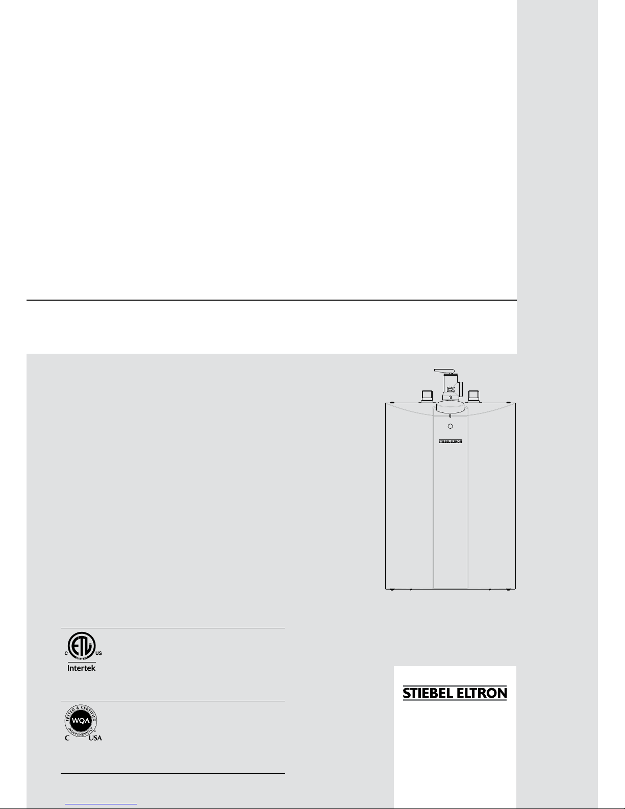
MINI-TANK ELECTRIC WATER HEATERS
CALENTADORES DE AGUA ELÉCTRICOS DE MINI-TANQUE
CHAUFFE-EAU ÉLECTRIQUES À MINI-RÉSERVOIR
» SHC 2.5
» SHC 4
» SHC 6
Conforms to ANSI / UL Std. 174
Certified to CAN/ CSA Std. C22.2 No. 110
Conforme a ANSI/UL Std. 174
Certificación con CAN/CSA Std. C22.2 No. 110
Conforme à la norme ANSI/UL Std. 174
Certifié à la norme CAN/CSA Std. C22.2 No. 110
Tested and certified by WQA to NSF/ANSI372
for lead free compliance.
Probado y certificado por WQA NSF/ANSI 372 para
el cumplimiento de las regulaciones sin plomo.
Testé et certifié par WQA à la NSF/ANSI 372 pour
une utilisation sans plomb.
2 | SHC 2.5 / SHC 4 / SHC 6 WWW.STIEBEL-ELTRON-USA.COM
TABLE OF CONTENTS | OPERATION | INSTALLATION
OPERATION
IMPORTANT SAFETY
INSTRUCTIONS
!
WARNING:
When using electrical appliances, basic safety precautions to reduce the risk of fire, electric shock, or injury
to persons should be followed, including:
1 READ ALL INSTRUCTIONS BEFORE USING THE
WATER HEATER.
2 This water heater must be grounded. Connect
only to properly grounded outlet. See the special
grounding instructions in chapter 9, “Electrical Connection”, pg. 6.
3 Install or locate this water heater only in accordance
with the provided installation instructions.
4 Use this water heater only for its intended use as
described in this manual.
5 Do not use an extension cord with this water heater.
If no receptacle is available adjacent to the water
heater, contact a qualified electrician to have one
properly installed.
6 As with any appliance, close supervision is neces-
sary when used by children.
7 Do not operate this water heater if it has a damaged
cord or plug, if it is not working properly, or if it has
been damaged or dropped.
8 This water heater should be serviced only by
qualified service personnel. Contact nearest authorized service facility for examination, repair, or
adjustment.
SAVE THESE INSTRUCTIONS
OPERATION
1. General Information �����������������������������������������3
2. Safety Precautions �������������������������������������������3
3. Register your product ���������������������������������������4
4. General Description ������������������������������������������ 4
5. Technical Description ����������������������������������������4
6. General Recommendations ���������������������������������4
INSTALLATION
7. Mounting the Unit ��������������������������������������������5
8. Plumbing Connections ���������������������������������������5
8.1 Filling the Water Heater ________________________________________ 6
9. Electrical Connection ����������������������������������������6
10. Settings �������������������������������������������������������6
11. Maintenance Instructions �����������������������������������7
11.1 Descaling the heating element ________________________________ 7
11.2 Venting the T&P relief valve ___________________________________ 7
11.3 Draining the water heater _____________________________________ 7
11.4 Removing the cover _____________________________________________ 7
11.5 Removing the heating element _______________________________ 8
11.6 De-scaling the heating element ______________________________ 8
11.7 Replacing the heating element _______________________________ 8
11.8 Changing the anode rod ________________________________________ 8
11.9 Safety Shut-off ___________________________________________________ 9
12. Technical Data ������������������������������������������������9
12.1 Dimensions, SHC 2.5 ___________________________________________ 10
12.2 Dimensions, SHC 4 ______________________________________________10
12.3 Dimensions, SHC 6 ______________________________________________10
12.4 Wiring diagram _________________________________________________ 10
13. Warranty ���������������������������������������������������� 11
OPERATION
GENERAL INFORMATION
ENGLISH
WWW.STIEBEL-ELTRON-USA.COM SHC 2.5 / SHC 4 / SHC 6 | 3
1. General Information
!
CAUTION:
To reduce the risk of excessive pressures and temperatures in this water heater, install temperature and
pressure protective equipment required by local codes
and no less than a combination temperature and pressure relief valve certified by a nationally recognized
testing laboratory that maintains periodic inspection
of production of listed equipment or materials, as
meeting the requirements for relief valves and automatic gas shutoff devices for hot water supply systems, ANSI Z21.22. This valve must be marked with a
maximum set pressure not to exceed the marked maximum working pressure of the water heater. Install the
valve into an opening provided and marked for this
purpose in the water heater, and orient it or provide
tubing so that any discharge from the valve exits only
within 6 inches above, or at any distance below, the
structural floor, and does not contact any live electrical part. The discharge opening must not be blocked
or reduced in size under any circumstances.
Read this entire manual. Failure to follow all the guides, instructions and rules could cause personal injury or property damage.
Improper installation, adjustment, alteration, service and use of
this unit can result in serious injury.
This unit must be installed by a licensed electrician and plumber.
The installation must comply with all national, state and local
plumbing and electric codes. Proper installation is the responsibility of the installer. Failure to comply with the installation and
operating instructions or improper use voids the warranty.
Save these instructions for future reference. The installer should
leave these instructions with the consumer.
If you have any questions regarding the installation, use or operation of this water heater, or if you need any additional installation
manuals, please call our technical service line at 800-582-8423
(USA and Canada only). If you are calling from outside the USA
or Canada, please call 413-247-3380 and we will refer you to a
qualified Stiebel Eltron service representative in your area.
1 Do not locate the water heater where water lines could be
subject to freezing temperatures.
2 It is recommended to have a floor drain nearby to permit
easy draining of the unit if necessary.
3 Install the water heater so that in the event of a leak, the
resulting flow of water will not cause damage to the area
around the water heater. Under no condition is the manufacturer liable for any water damage in connection with this
water heater.
4 When installing the water heater, ensure that clearance
around the unit is provided, for ease of maintenance and
service.
!
This is the safety alert symbol.
It is used to alert you to potential personal injury hazard. Obey all safety messages that follow this symbol
to avoid possible injury or death.
2. Safety Precautions
!
PLEASE READ AND FOLLOW THESE INSTRUCTIONS:
Failure to follow these instructions could result in serious bodily injury or death.
The unit must be installed by a licensed plumber. The
installation must comply with all national, state and
local plumbing and electric codes.
Service of the unit must be performed by a qualified
service agency.
Before proceeding with any installation, adjustment,
alteration, or service of this unit the power cord
should be unplugged. Failure to do so could result in
serious personal injury or death.
Never remove the unit‘s cover unless the electricity
servicing the unit is turned off. Failure to do so could
result in personal injury or death.
Do not store or use gasoline or other flammable vapors or liquids in the vicinity of this or any other appliance.
!
DANGER:
Water temperatures over 125 °F (52 °C) can cause
severe burns instantly or death from scalding. A hot
water scalding potential exists if the thermostat on
the unit is set too high. Households with small children, disabled or elderly persons may require that the
thermostat be set at 120 °F (49 °C) or lower to prevent
possible injury from hot water.
!
WARNING:
This water heater must be installed strictly in accordance with the instructions enclosed and local electric
and building codes. It is also possible that connections
to the water heater itself may develop leaks. It is
therefore imperative that the water heater be installed
so that any water is directed to an adequate drain in
such a way that water damage to the building, furniture, carpeting or other property cannot occur. Neither
the manufacturer nor the distributor can be held responsible for damage caused by water from the water
heater, temperature pressure relief valve, or related
fittings where adequate provision to drain such water
has not been provided.
!
CAUTION:
Hydrogen gas can be produced in a hot water system
served by this heater that has not been used for a long
period of time (generally 2 weeks or more). Hydrogen
gas is extremely flammable.
To reduce the risk of injury under these conditions, it
is recommended that the hot water faucet be opened
for several minutes at the kitchen sink before using
any electrical appliance connected to the hot water
system.
When hydrogen is present, there will probably be an
unusual sound such as air escaping through the pipe
as the water begins to flow. There should be no smoking or open flame near the faucet at the time it is open.
Monthly manual venting of the T&P valve will reduce
this effect. See 11.2, “Venting the T&P relief valve”,
pg. 7.
OPERATION
REGISTER YOUR PRODUCT
4 | SHC 2.5 / SHC 4 / SHC 6 WWW.STIEBEL-ELTRON-USA.COM
3. Register your product
NOTE:
You must register this product within 90 days of
purchase on our web site in order to activate any
standard warranty or to be eligible for the extended
warranty. Go to our website at:
www.stiebel-eltron-usa.com and click on “Register
Your Product".
Before beginning the registration process, we suggest
that you gather the necessary information as follows:
Model, Example: SHC 2.5 (from the label that is on the
top of the unit in the center)
Number listed after “Nr.”
Place of Purchase
Purchase Date
First & Last Name
Email address
Physical Address
Phone Number
If you have any questions concerning the registration
process or warranty options, please contact Stiebel Eltron
USA directly at (800)-582-8423.
4. General Description
These SHC water heaters can be used in most point-of-use applications. They are designed to supply hot water for hand wash
and kitchen sinks in a residential, commercial or industrial environment.
These water heaters can replace traditional hot water systems
which consist of a central hot water heater with hot water piping
going to several draw-off points.
The SHC water heaters are lightweight and compact and manufactured for easy installation. The units are designed to be mounted
on the wall. These units are designed to operate under normal
street water pressure.
5. Technical Description
The pressure vessel of the water heater is welded glass-lined steel
and is equipped with a sacrificial anode rod. The thermal insulation is made of polystyrene.
The water heater is equipped with both a thermostat and a high
limit temperature switch. A temperature/pressure relief valve is
supplied with the unit.
6. General Recommendations
The installation must be carried out by licensed professionals. All
state and local codes must be adhered to.
The manufacturer will not be liable for any damages because of
failure to comply with these installation instructions or because
of improper installation performed by an unqualified installer.
!
NOTE:
The T&P valve must be manually vented monthly. See
11.2, “Venting the T&P relief valve”, pg. 7.
!
NOTE:
Choose a location that allows easy access for maintenance or servicing.
The water heater should be installed with at least
8˝ (203 mm) of clearance on the top and sides of the
unit.
ENGLISH
WWW.STIEBEL-ELTRON-USA.COM SHC 2.5 / SHC 4 / SHC 6 | 5
INSTALLATION
MOUNTING THE UNIT
INSTALLATION
7. Mounting the Unit
!
NOTICE:
Unit must be installed in a vertical position with the
water fittings pointing upward.
WARNING:
Do not install unit where it would routinely be
splashed with water. Electric shock may result.
CAUTION:
Hot water outlet pipes leaving unit can be hot to the
touch. Insulation must be used for hot water pipes
below a height of 36˝ (.91 m) due to burn risk to children.
!
NOTICE:
This unit should not be installed in a location where
it may be exposed to freezing temperatures (less
than 36°F (2°C). If the unit may be subject to freezing temperatures, all water must be drained from the
unit. Failure to comply with this instruction voids all
warranties.
The unit should be located in an area where water
leakage from the unit or connections will not result
in damage to the area adjacent to the unit. If such a
location cannot be avoided it is recommended that a
drain pan be installed under the unit.
1 Drill two ¼ holes in the wall where the water heater will be
mounted.
2 Install plastic wall anchors.
3 Fasten wall mounting bracket to the wall.
4 Hook water heater to the mounting bracket.
5 Pull downwards on the water heater to properly seat it on
the bracket.
8. Plumbing Connections
!
IMPORTANT:
If water pipes are made of copper or bronze, use
dielectric connections to prevent heater corrosion.
Failure to provide dielectric insulation may result in
premature tank or nipple failure and may void your
warranty.
!
IMPORTANT:
In order to avoid water coming in contact with the
male pipe threads, ensure that all thread pitches are
sealed properly. It is especially important that the
first thread pitches be fully sealed to ensure no leakage will occur after the water connections have been
securely made. Failure to properly seal pipe thread
pitches may allow water to come in contact with the
male threads and create corrosion.
!
NOTICE:
Hard water or water with a high mineral count may
damage the unit. Damage to the unit caused by scale
or a high mineral count is not covered under the warranty.
CAUTION:
To reduce the risk of excessive temperature and
pressure in the water heater, a temperature/pressure
(T&P) relief valve has been installed.
CAUTION:
Always fill the unit’s tank with water before plugging
the water heater’s cord into an electrical outlet. Failure to do so will result in permanent damage to the
water heater.
!
NOTICE:
When a water heater is installed in a closed water
supply system, such as one having a back-flow preventer in the cold- water supply, means shall be
provided to control thermal expansion. Contact the
water supplier or local plumbing inspector for information regarding the control of this situation.
Connect the cold water pipe to the cold water connection on the
unit (blue). Connect the hot water pipe to the hot water connection
on the unit (red).
Ensure that the water heater is installed in a level position.
Install a shut-off on the cold water side of the water heater. This
is for emergency shut-off. It must be kept open when the water
heater is operating.
When using copper piping, solder a piece of tubing to a threaded
fitting (union) before screwing the adapter to the tank.
BRAIDED FLEX HOSE CONNECTORS ARE ALSO RECOMMENDED.
DO NOT APPLY HEAT DIRECTLY TO INLET OR OUTLET CONNECTIONS.
A certified T&P valve is mounted to the water heater by the manu-
facturer with the outlet oriented to the right. If this position needs
to be changed, leakage may occur, especially if it will be screwed
counter-clockwise, and the T&P valve may need to be resealed.
After all plumbing work has been completed, the T&P valve needs
to be checked for proper tightness.
During heating, the water volume and water pressure increases
in the tank. It is possible for water to leak from the safety valve,
this is normal.
It is recommended to install a check valve on the cold water inlet
supply line to the unit so that air pockets can be purged through
the T&P valve.
6 | SHC 2.5 / SHC 4 / SHC 6 WWW.STIEBEL-ELTRON-USA.COM
INSTALLATION
ELECTRICAL CONNECTION
4
3
1
2
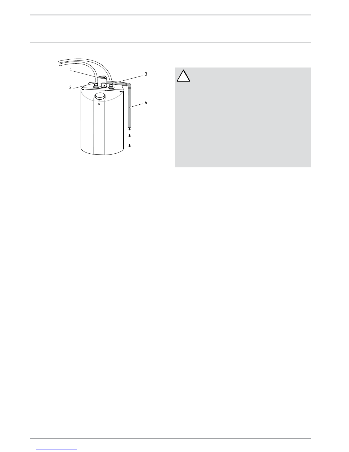
1 Temperature/Pressure relief valve
2 Hot water outlet
3 Cold water inlet
4 Discharge pipe
Install a discharge pipe from the relief valve terminating at a sink
or drain. Orient the tubing so that discharge will exit within 6˝
(152 mm) above or at any distance below the structural floor, and
cannot contact any live electrical parts.
DO NOT CAP OR THREAD THE END OF THE DISCHARGE PIPE, IT
MUST BE UNOBSTRUCTED AND FULL SIZE.
The T&P valve is certified by a nationally recognized test laboratory
that maintains periodic inspection of the listed equipment, and
meets the requirements for relief valves and automatic shut-off
devices for hot water supply systems ANSI Z21.22.
The T&P valve is marked with a maximum pressure, which does
not exceed the maximum working pressure of the water heater
(150 PSI).
THE DISCHARGE PIPE
- Must not be smaller in size than the outlet pipe size of the
valve, or have reducing couplings.
- Must not be plugged or blocked.
- Must be of material suitable for hot water.
- Must not be over 15´ (4.5 m) in length.
- Must not have more than two elbows.
- Must terminate at an adequate drain.
- Must not have a valve between the relief valve and the tank.
8.1 Filling the Water Heater
To fill the water heater:
1 Open the hot water faucet.
2 Open the cold water supply valve.
3 When water runs out of the faucet, the tank is filled.
4 Close the hot water faucet.
5 Manually vent the T&P valve. See 11.2, “Venting the T&P re-
lief valve”, pg. 7.
6 Check entire system for leaks.
9. Electrical Connection
!
CAUTION:
Always fill the unit’s tank with water before plugging
the water heater’s cord into an electrical outlet. Failure to do so will result in permanent damage to the
water heater.
NOTICE:
The water heater must be connected to a grounded
outlet.
This water heater was designed for use at 110 120V. Do not use this water heater with any other
voltage. Failure to use the correct voltage may result
in personal injury or property damage.
The heater is supplied with an electrical cable with a
plug. If the cable is damaged or length not sufficient,
it must be replaced by a licensed electrician.
To be certain that all the air is out of the system, open the hot
water faucet on your fixtures until constant water flows from them.
Otherwise, damage to the device may occur.
Connect the water heater to a GROUNDED OUTLET.
The unit is fitted with a power cord to connect the water heater
to a receptacle. State and local codes must be adhered to. Install
the correct breaker at the circuit breaker panel.
The water heater was manufactured and wired in accordance with
the UL requirements.
A temperature high limit with manual reset has been factory installed to interrupt the power supply in the event of a thermostat
failure.
DO NOT use this water heater with any other voltage. Failure to
use the correct voltage may result in personal injury or property
damage.
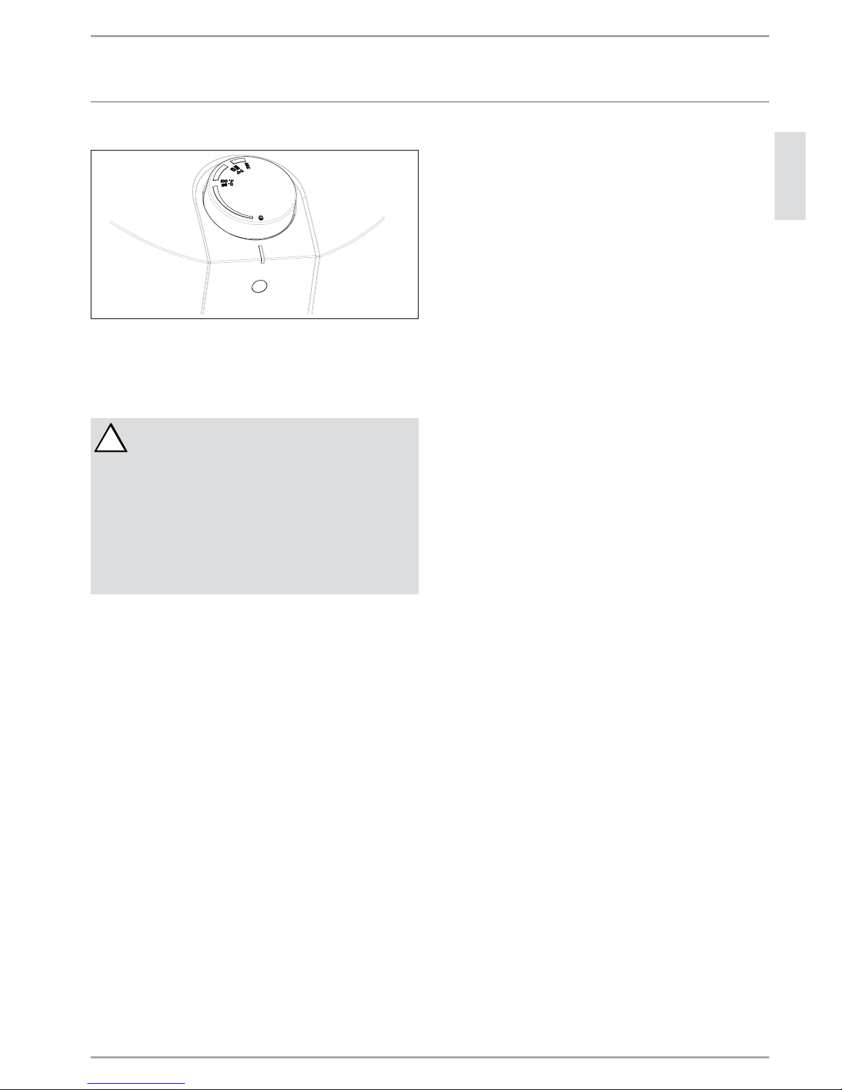
10. Settings
The water heater is equipped with an adjustable thermostat that
automatically controls the water temperature. The indicator lamp
remains lit only when the water is being heated.
The temperature is adjusted by turning the knob counterclockwise
(to the left) to increase the temperature and clockwise (to the right)
to decrease the temperature.
The water heater thermostat can be set to guard against freezing.
This position keeps the internal temperature above the freezing
point.
The piping outside of the water heater and the faucet are not
protected against freezing.
ENGLISH
WWW.STIEBEL-ELTRON-USA.COM SHC 2.5 / SHC 4 / SHC 6 | 7
INSTALLATION
MAINTENANCE INSTRUCTIONS
Freeze protection setting
D0000034989
Temperature setting
The water heater thermostat is factory set at 120°F (49°C).
11. Maintenance Instructions
!
WARNING:
Before servicing or cleaning the water heater, disconnect the water heater from the electrical outlet.
The temperature/pressure relief valve must be manually operated once per month. Caution should be
taken to ensure that:
1. No one is near the temperature/pressure relief
valve discharge pipe.
2. The water discharged will not cause any bodily
injury or property damage. The water may be extremely hot.
Do not attempt to repair the water heater.
Call your licensed plumber or electrician for service. Unplug the
unit whenever the water supply is turned off.
Before calling for service, make sure that:
1 The heater is properly filled.
2 The electrical supply has not been interrupted.
11.1 Descaling the heating element
Approximately every two years, it is advisable to descale the heating element and to check the condition of the magnesium anode,
replacing it if the diameter is less than 3/8˝ (10 mm). See 11.8,
“Changing the anode rod”, pg. 8.
11.2 Venting the T&P relief valve
It is recommended to install a check valve on the cold water inlet
supply line to the unit so that air pockets can be purged through
the T&P valve. The temperature/pressure relief valve must be
manually operated once per month. Caution should be taken to
ensure that:
1 No one is near the temperature/pressure relief valve dis-
charge pipe.
2 The water discharged will not cause any bodily injury or
property damage. The water may be extremely hot.
11.2.1 T&P venting / testing procedure
1 Before venting, make sure it is known how to shut off the
water supply to the heater. It is not necessary initially, but
may become so if the T&P valve does not reseat properly
when vented, which may cause water to leak.
2 On the top of the T&P valve is a small handle that lifts a pin in
the center of the valve. Lift the handle up so the valve opens,
then release it so it closes. This will vent the T&P valve and at
the same time test if it is functioning correctly.
3 If the valve is stuck so that it does not open or does not close
it should be replaced immediately.
4 The T&P valve may take more than one attempt to reseat cor-
rectly. If this is the case, try re-opening the valve and quickly
releasing it, allowing it to slap shut. This action does not
damage the valve.
5 If after repeated attempts the valve does not reseat properly
and continues to leak water, it should be replaced. If the
valve fails this test it was already malfunctioning and was not
offering the protection needed.
6 Immediately close the cold water inlet to the heater. Replace
the malfunctioning T&P valve with a new one.
Failure to install and maintain a properly functioning and properly
listed temperature/pressure relief valve will release the manufacturer and distributor of this water heater from any claim which
might result from excessive temperature or pressure. Regular
venting/testing may increase the life of the valve.
11.3 Draining the water heater
Some service work requires draining the water heater. This should
be done in the following manner:
1 Unplug the water heater.
2 Open the hot water faucet to let the hot water out. Let it con-
tinue to flow until cold water runs from the faucet.
3 Turn off the cold water supply to the heater.
4 Close the hot water faucet
5 Disconnect the heater from both the hot and cold water
pipes.
6 Carefully detach the water heater from the wall.
7 Tilt the water heater to drain out the remaining water.
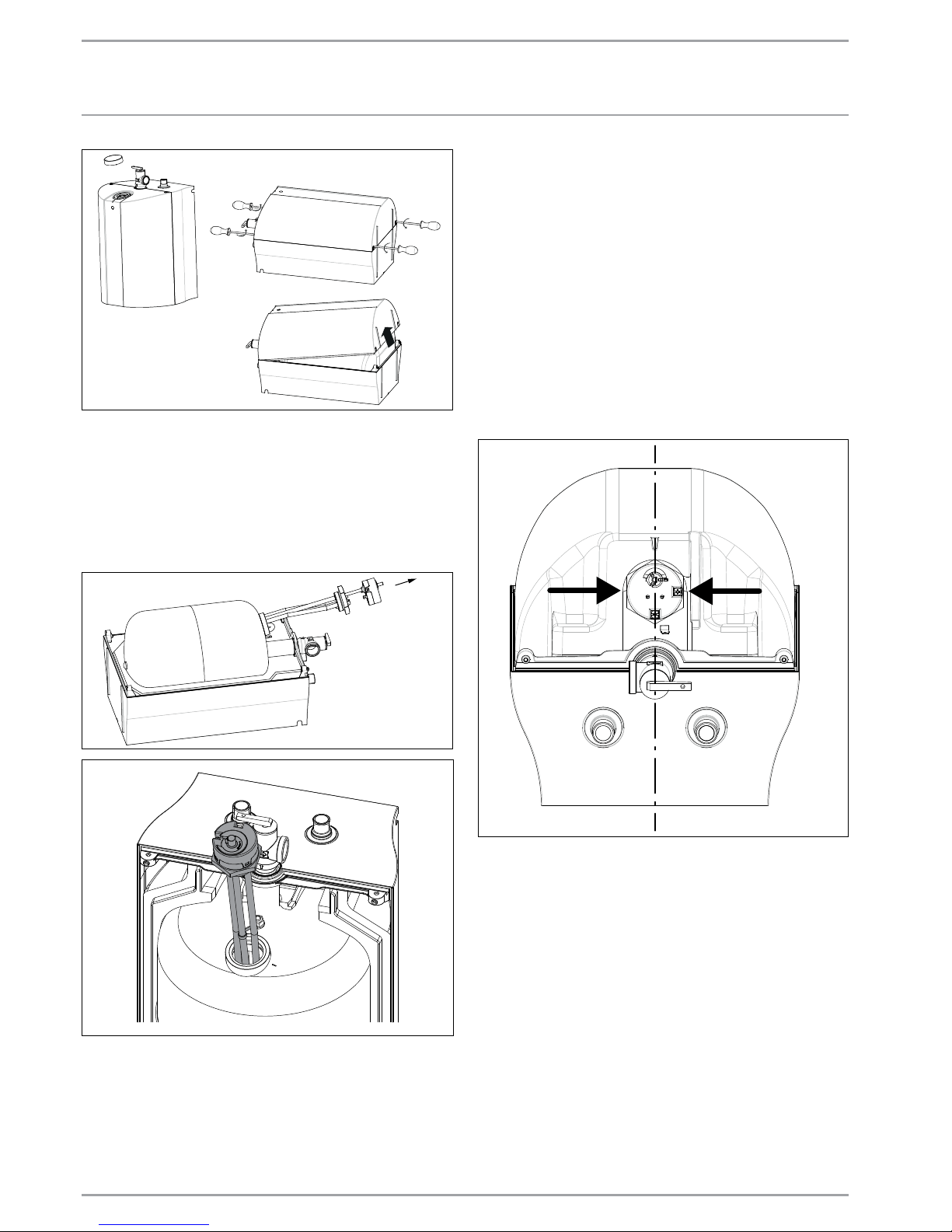
11.4 Removing the cover
1 Remove the temperature control knob from the top of the
unit.
2 Remove the screws from the cover.
3 Remove the cover by tilting the bottom side and lifting off the
cover. Cover should come right off.
8 | SHC 2.5 / SHC 4 / SHC 6 WWW.STIEBEL-ELTRON-USA.COM
INSTALLATION
MAINTENANCE INSTRUCTIONS
D0000034990
11.5 Removing the heating element
1 Unplug and drain the water heater. See 11.3, “Draining the
water heater”, pg. 7.
2 Remove the cover. See 11.4, “Removing the cover”, pg. 7.
3 Disconnect the line wires from the thermostat.
4 Remove the thermostat from the heating element.
5 Using a suitable wrench, unscrew the heating element.
6 Remove the heating element from the tank.
11.6 De-scaling the heating element
Scale deposit can affect the heating capacity of the heating element. Scale can even cause the element to burn out. The element
can be descaled either chemically or manually.
1 Remove the heating element. See 11.5, “Removing the heat-
ing element”, pg. 8.
2 To descale chemically, soak the heating element in white vin-
egar or other descaling solution, then rinse well.
3 To descale manually, use a nonmetallic (soft) tool; brush the
crust off the element. Make sure you do not damage the sur-
face of the heating element.
4 Reinstall the heating element.
5 Refill the water heater with water and check for leaks before
connecting the power.
11.7 Replacing the heating element
1 Unplug and drain the water heater. See 11.3, “Draining the
water heater”, pg. 7.
2 Remove the cover. See 11.4, “Removing the cover”, pg. 7.
3 Remove the heating element. See 11.5, “Removing the heat-
ing element”, pg. 8.
4 Install and seal the new element. Make sure that the heating
element is positioned correctly.
D0000036026
5 Remount all the line wires to their original location.
6 Refill the water heater with water and check for leaks before
connecting the power.
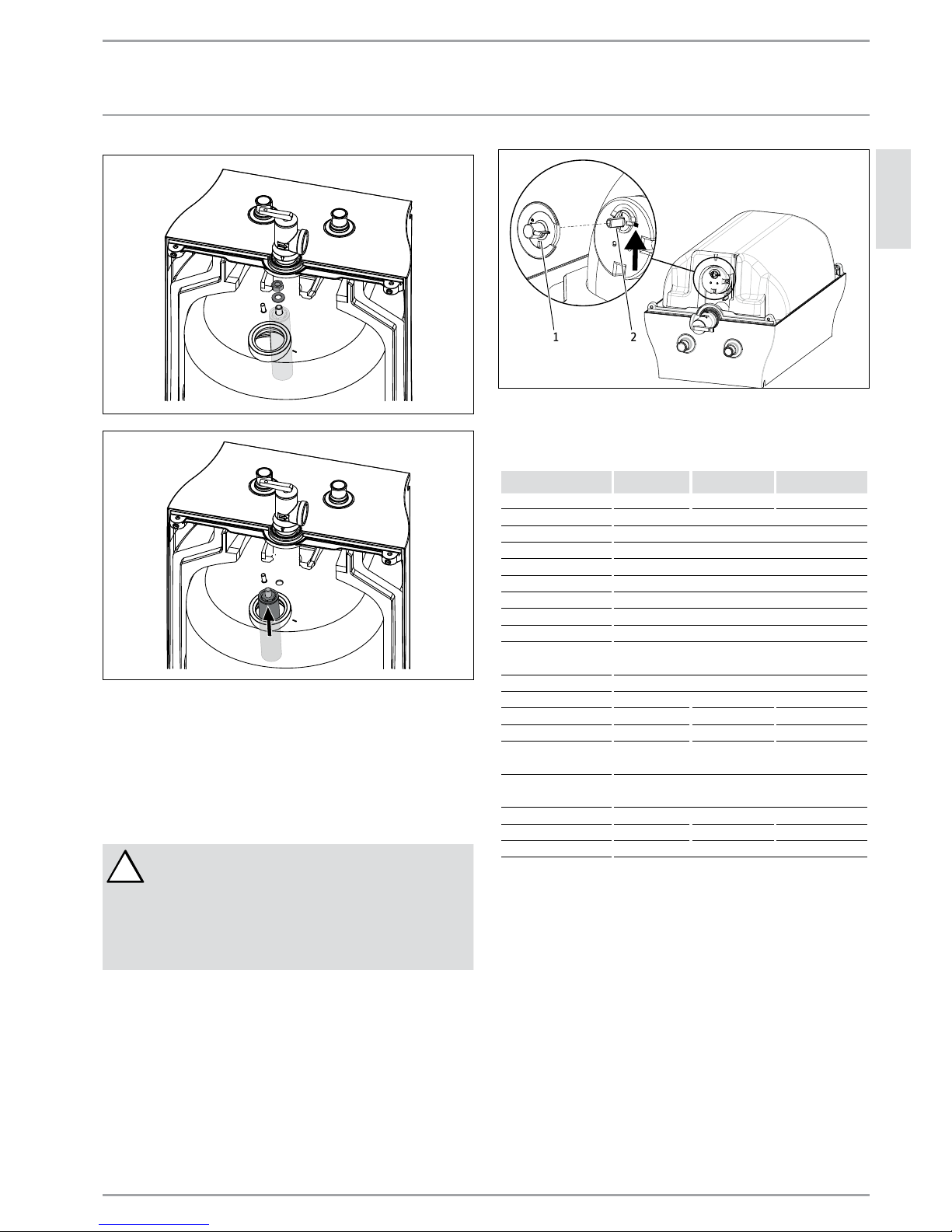
11.8 Changing the anode rod
A magnesium anode is used to extend the life of the tank. Permanent removal of this anode for any reason will void the warranty.
Depending on conditions, the magnesium anode rod may need to
be changed approximately every two years. Galvanic and electrolytic corrosion can destroy a tank with a spent anode rod. Rusty
water is usually an indicator of a spent anode rod.
1 Unplug and drain the water heater. See 11.3, “Draining the
water heater”, pg. 7.
2 Remove the cover. See 11.4, “Removing the cover”, pg. 7.
3 Remove the heating element. See 11.5, “Removing the heat-
ing element”, pg. 8.
4 Secure the anode using pliers.
5 Unscrew the nut and remove the anode rod through the
opening of the heating element port.
ENGLISH
WWW.STIEBEL-ELTRON-USA.COM SHC 2.5 / SHC 4 / SHC 6 | 9
INSTALLATION
TECHNICAL DATA
6 Fit a new anode rod including the sealing gasket and sup-
porting washer into the tank opening and secure it with the
included washer and nut. Use a tightening torque of 1100
N•cm ±120 N•cm.
7 Refit all the wires and the heating element.
8 Refill the water heater with water and check for leaks before
connecting the power.
11.9 Safety Shut-off
!
WARNING:
Never lock the sliding reset plunger.
DANGER:
Water temperatures over 125°F (52°C) can cause severe burns instantly or death from scalding. Do not
attempt to reset the high limit switch without first
cooling down the water inside the water heater.
11.9.1 Resetting high temperature shut-off system
1 Unplug the water heater.
2 Remove the cover. See 11.4, “Removing the cover”, pg. 7.
3 Unplug the adapter (1) from the controller shaft.
4 Press in button (2) with an appropriate tool.
5 Reassemble the adapter in the correct position.
6 Reassemble the cover of the heater and tighten.
7 Reassemble the thermostat control knob.
1 2
1 Adapter
2 Button
12. Technical Data
SHC 2.5 SHC 4 SHC 6
Item No. 233219 234046 235089
Voltage 110–120 V
Wattage 1300 W
Amperage 11.3 A
Phase Single, 1/N/PE
Frequency 50/60 Hz
Type of installation Under sink
Internal tank material Steel
Enclosure material Plastic
Thermal insulation
material
Polystyrene
Color white
Nominal water volume 2.65 gal / 10 l 4 gal / 15 l 6 gal / 22.7 l
Standby energy loss10.37 kWh/day 0.39 kWh/day 0.47 kWh/day
Recovery time 18 minutes 27 minutes 45 minutes
Temperature setting
range
86–140 °F / 30–60 °C
Max. operating
pressure
150 psi / 1.0 MPa
Weight empty 15.9 lbs / 7.2 kg 19.8 lbs / 9.0 kg 26.2 lbs / 11.9 kg
Weight full 38.6 lbs 17.5 kg 52.9 lbs / 24.0 kg 76.3 lbs / 34.6 kg
Water connections 1/2˝ NPT
1
Measure d at 131°F / 55°C set point temperature in 68°F / 20°C ambient air temperature.
10 | SHC 2.5 / SHC 4 / SHC 6 WWW.STIEBEL-ELTRON-USA.COM
INSTALLATION
TECHNICAL DATA
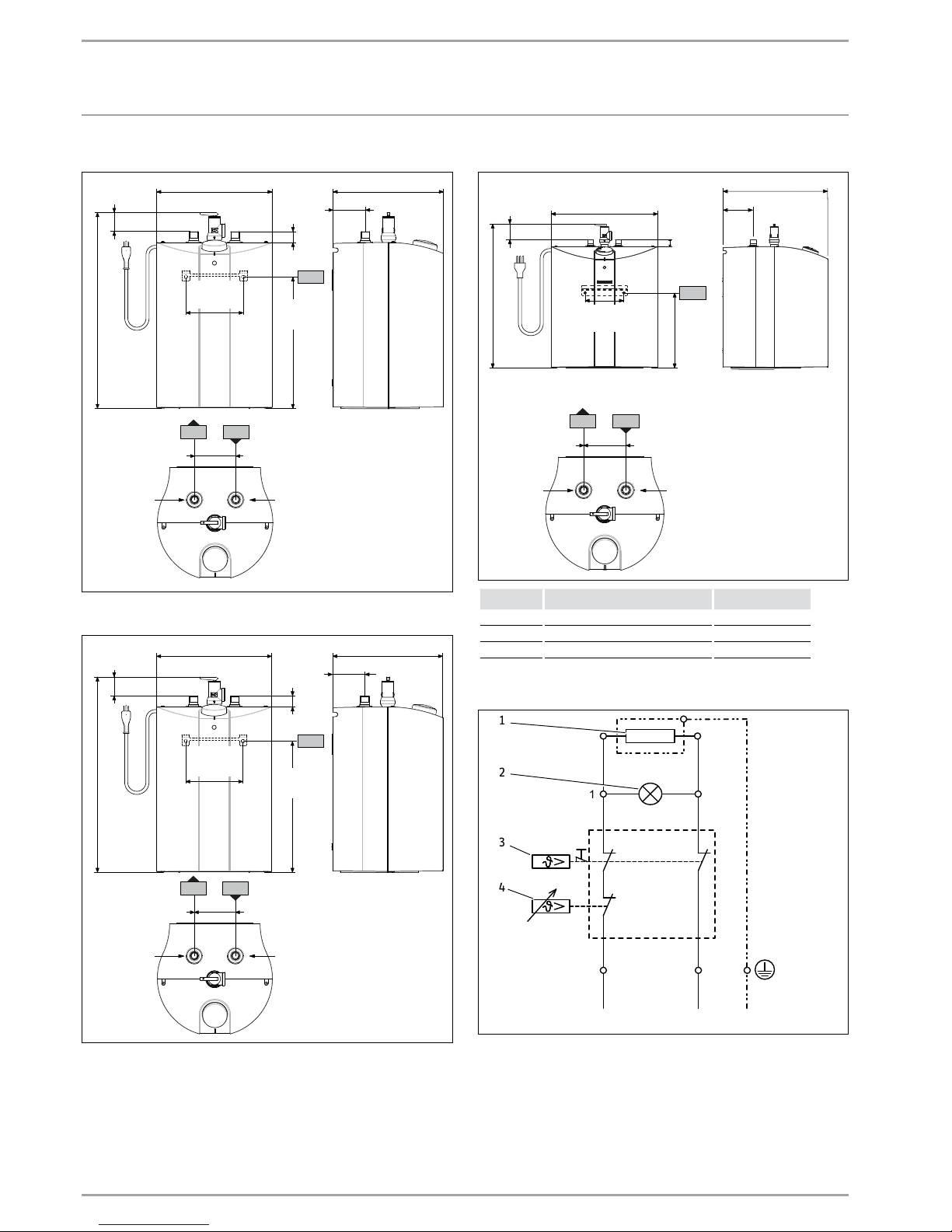
12.1 Dimensions, SHC 2.5
i13
c06
c01
315/16˝ (100 mm)
10
5
/8˝ (270 mm)
3
1
/8˝ (80 mm)
11˝
(280 mm)
1
3
/4˝
(45 mm)
18
11
/16˝
(475 mm)
5
1
/2˝
(140 mm)
125/8˝
(320 mm)
1
1
/16˝
(26 mm)
12.2 Dimensions, SHC 4
125/8˝ (320 mm)
12
1
/2˝ (318 mm)
3
1
/8˝ (80 mm)
15
/16˝
(23 mm)
1
15
/16˝
(49 mm)
19
3
/4˝
(501 mm)
7
7
/8˝
(200 mm)
137/16˝
(342 mm)
c06
c01
i13
315/16˝ (100 mm)
12.3 Dimensions, SHC 6
2¼˝
(57 mm)
151/8˝ (385 mm)
i13
4⅜˝ (110 mm)
15˝ (380 mm)
1˝
(25 mm)
5½˝
(140 mm)
11
1
/8˝
(283 mm)
20½˝
(520 mm)
c06
c01
315/16˝ (100 mm)
Label Description Connection
c01 Cold water inlet ½ NPT male
c06 Hot water outlet ½ NPT male
i13 Wall-mounting locations
12.4 Wiring diagram
L
A B
N PE
1 2
D0000035810
4
5
3
2
1
1 Heating element
2 Lamp indicator
3 Cut-off
4 Thermostat
5 Tank
ENGLISH
WWW.STIEBEL-ELTRON-USA.COM SHC 2.5 / SHC 4 / SHC 6 | 11
WARRANTY
WARRANTY
17 West Street
West Hatfi eld, MA 01088
TOLL FREE 800.582.8423
PHONE 413.247.3380
FAX 413.247.3369
info
@
stiebel-eltron-usa.com
www.stiebel-eltron-usa.com
MINI-TANK DOMESTIC HOT WATER HEATERS
All SHC Models
LIMITED WARRANTY
Subject to the terms and conditions set forth in this limited
warranty, Stiebel Eltron, Inc. (the “Manufacturer”) hereby
warrants to the original purchaser (the “Owner”) that each
Mini-Tank Domestic Hot Water Heater (the “Heater”) shall
not (i) leak due to defects in the Manufacturer’s materials
or workmanship for a period of six (6) years from the date
of purchase or (ii) fail due to defects in the Manufacturer’s
materials or workmanship for a period of two (2) years
from the date of purchase. As Owner’s sole and exclusive
remedy for breach of the above warranty, Manufacturer
shall, at the Manufacturer’s discretion, send replacement
parts for local repair; retrieve the unit for factory repair, or
replace the defective Heater with a replacement unit with
comparable operating features. Manufacturer’s maximum
liability under all circumstances shall be limited to the
Owner’s purchase price for the Heater.
This limited warranty shall be the exclusive warranty
made by the Manufacturer and is made in lieu of all other
warranties, express or implied, whether written or oral,
including, but not limited to warranties of merchantability
and fi tness for a particular purpose. Manufacturer shall
not be liable for incidental, consequential or contingent
damages or expenses arising directly or indirectly from any
defect in the Heater or the use of the Heater. Manufacturer
shall not be liable for any water damage or other damage
to property of Owner arising, directly or indirectly,
from any defect in the Heater or the use of the Heater.
Manufacturer alone is authorized to make all warranties
on Manufacturer’s behalf and no statement, warranty or
guarantee made by any other party shall be binding on
Manufacturer.
Manufacturer shall not be liable for any damage
whatsoever relating to or caused by:
1. any misuse or neglect of the Heater, any accident to
the Heater, any alteration of the Heater, or any other
unintended use;
2. acts of God and circumstances over which
Manufacturer has no control;
3. installation of the Heater other than as directed by
Manufacturer and other than in accordance with
applicable building codes;
4. failure to maintain the Heater or to operate the Heater
in accordance with the Manufacturer’s specifi cations;
5. operation of the Heater under fl uctuating or excessive
water pressure or in the event the Heater is supplied
with non-potable water, for any duration;
6. improper installation and/or improper materials used
by any installer and not relating to defects in parts or
workmanship of Manufacturer;
7. moving the Heater from its original place of installation;
8. exposure to freezing conditions;
9. water quality issues such as corrosive water, hard water,
and water contaminated with pollutants or additives;
10. not continuously supplying the unit with water aka
“dry-fi ring”.
Should Owner wish to return the Heater to manufacturer
for repair or replacement under this warranty, Owner
must fi rst secure written authorization from Manufacturer.
Owner shall demonstrate proof of purchase, including a
purchase date, and shall be responsible for all removal
and transportation costs. If Owner cannot demonstrate a
purchase date this warranty shall be limited to the period
beginning from the date of manufacture stamped on the
Heater. Manufacturer reserves the right to deny warranty
coverage upon Manufacturer’s examination of the Heater.
This warranty is restricted to the Owner and cannot be
assigned.
Some States and Provinces do not allow the exclusion
or limitation of certain warranties. In such cases, the
limitations set forth herein may not apply to the Owner. In
such cases this warranty shall be limited to the shortest
period and lowest damage amounts allowed by law. This
warranty gives you specifi c legal rights and you may also
have other rights which vary from State to State or Province
to Province.
Owner shall be responsible for all labor and other charges
incurred in the removal or repair of the Heater in the fi eld.
Please also note that the Heater must be installed in such a
manner that if any leak does occur, the fl ow of water from
any leak will not damage the area in which it is installed.
This Warranty is valid for U.S.A. & Canada only. Warranties
may vary by country. Please consult your local Stiebel Eltron
Representative for the Warranty for your country.
13. Warranty
 Loading...