

Page 1
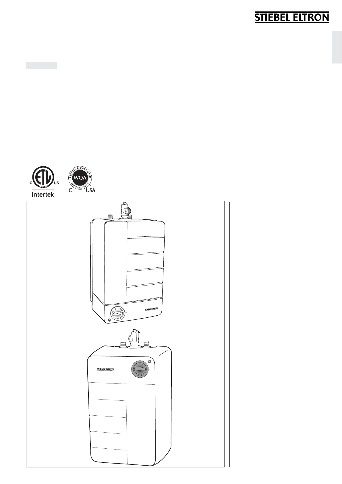
SHC 2.5, SHC 4
English
MINI-TANK ELECTRIC WATER HEATERS
INSTALLATION INSTRUCTIONS FOR THE LICENSED PLUMBER
The SHC series is tested and
certified by WQ A against
NSF/ANSI 372 for “lead free“
compliance.
English
SHC 2.5
SHC 4
English Table of contents
1 General information ___________________________________2
2 Safety precautions _____________________________________2
3 General description ____________________________________3
4 Technical description __________________________________3
5 Technical specifi cations _______________________________3
6 General recommendations ___________________________3
7 Mounting the unit ______________________________________ 3
8 Plumbing connections ________________________________3
9 Electrical connec tion __________________________________4
10 Sett ings ___________________________________________________4
11 Maintenance instructions ____________________________5
12 Warrant y _________________________________________________6
– 1 –
Page 2
1 General Information
2 Safety Precautions
Read this entire manual. Failure to follow all
the guides, instructions and rules could cause
personal injury or property damage. Improper
installation, adjustment, alteration, service and
use of this unit can result in serious injury.
This unit must be installed by a licensed
electrician and plumber. The installation
must comply with all national, state and local
plumbing and electric codes. Proper installation
is the responsibility of the installer. Failure to
comply with the installation and operating
instructions or improper use voids the warranty.
Save these instructions for future reference.
Installer should leave these instructions with the
consumer.
If you have any questions regarding the
installation, use or operation of this water
heater, or if you need any additional installation
manuals, please call our technical service line at
800-582-8423 (USA and Canada only). If you are
calling from outside the USA or Canada, please
call USA 413-247-3380 and we will refer you to
a qualifi ed Stiebel Eltron service representative
in your area.
1. READ ALL INSTRUCTIONS BE FORE USING THE
WATER HEATER.
2. This water heater must be grounded. Connect
to properly grounded outlet only!
See chapter called “ELECTRICAL CONNECTION”.
3. Install or locate this water heater only in
accordance with the installation instructions.
4. Use this water heater for its intended use only
as described in this manual.
5. Do no use an extension cord with this water
heater. If no receptacle is available
adjacent to the water heater, contact a qualifi ed
electrician to have one properly installed.
6. As with any appliance, close supervision is
necessary when used by children.
7. Do not operate this water heater if it has a
damaged cord or plug, if it is not working
properly, or if it has been damaged or dropped.
8. Do not locate the water heater where water
lines could be subject to freezing temperatures.
9. It is recommended to have a fl oor drain nearby
to permit easy draining of the unit if necessary.
10. Install the water heater so that in the event of
a leak, the resulting fl ow of water will not cause
damage to the area around the water heater.
Under no condition is the manufacturer liable
for any water damage in connection with this
water heater.
11. When installing the water heater, ensure
that clearance around the unit is provided, for
ease of maintenance and service.
12. Only qualifi ed, licensed service personnel
should service this water heater. Contact the
nearest authorized licensed personnel for
inspection, repair or adjustment.
THIS IS THE SAFETY ALERT SYMBOL. IT
!
IS USED TO ALERT YOU TO POTENTIAL
PERSONAL INJURY HAZARD. OBEY ALL SAFETY
MESSAGES THAT FOLLOW THIS SYMBOL TO
AVOID POSSIBLE INJURY OR DEATH.
PLEASE READ AND FOLLOW THESE
!
INSTRUCTIONS. FAILURE TO FOLLOW
THESE INSTRUCTIONS COULD RESULT IN
SERIOIUS BODILY INJURY OR DEATH.
THE UNIT MUST BE INSTALLED BY A LICENSED
PLUMBER. THE INSTALLATION MUST COMPLY
WITH ALL NATIONAL, STATE AND LOCAL
PLUMBING AND ELECTRIC CODES.
SERVICE OF THE UNIT MUST BE PERFORMED
BY A QUALIFIED SERVICE AGENCY.
BEFORE PROCEEDING WITH ANY INSTALLATION,
ADJUSTMENT, ALTERATION, OR SERVICE OF
THIS UNIT THE POWER CORD SHOULD BE
UNPLUGGED. FAILURE TO DO SO COULD RESULT
IN SERIOUS PERSONAL INJURY OR DEATH.
NEVER REMOVE THE UNIT'S COVER UNLESS
THE ELECTRICITY SERVICING THE UNIT IS
TURNED OFF. FAILURE TO DO SO COULD RESULT
IN PERSONAL INJURY OR DEATH.
DO NOT STORE OR USE GASOLINE OR OTHER
FLAMMABLE VAPORS OR LIQUIDS IN THE
VICINITY OF THIS OR ANY OTHER APPLIANCE.
DANGER: WATER TEMPERATURES OVER
125°F CAN CAUSE SEVERE BURNS INSTANTLY
OR DEATH FROM SCALDING. A HOT WATER
SCALDING POTENTIAL EXISTS IF THE
THERMOSTAT ON THE UNIT IS SET TOO
HIGH. HOUSEHOLDS WITH SMALL CHILDREN,
DISABLED OR ELDERLY PERSONS MAY REQUIRE
THAT THE THERMOSTAT BE SET AT 120°F OR
LOWER TO PREVENT POSSIBLE INJURY FROM
HOT WATER.
WARNING: THIS WATER HEATER MUST
!
BE INSTALLED STRICTLY IN ACCORDANCE
WITH THE INSTRUCTIONS ENCLOSED AND
LOCAL ELECTRIC AND BUILDING CODES. IT IS
ALSO POSSIBLE THAT CONNECTIONS TO THE
WATER HEATER ITSELF MAY DEVELOP LEAKS.
IT IS THEREFORE IMPERATIVE THAT THE
WATER HEATER BE INSTALLED SO THAT ANY
WATER IS DIRECTED TO AN ADEQUATE DRAIN
IN SUCH A WAY THAT WATER DAMAGE TO THE
BUILDING, FURNITURE, CARPETING OR OTHER
PROPERTY CANNOT OCCUR. NEITHER THE
MANUFACTURER NOR THE DISTRIBUTOR CAN
B E HELD RESPONSIBLE FOR DAMAGE CAUSED
BY WATER FROM THE WATER HEATER,
TEMPERATURE PRESSURE RELIEF VALVE,
OR RELATED FITTINGS WHERE ADEQUATE
PROVISION TO DRAIN SUCH WATER HAS NOT
BEEN PROVIDED.
HYDROGEN GAS CAN BE PRODUCED IN
A HOT WATER SYSTEM SERVED BY THIS
HEATER THAT HAS NOT BEEN USED FOR LONG
TIME (GENERALLY TWO WEEKS OR MORE).
HYDROGEN GAS IS EXTREMELY FLAMMABLE,
TO REDUCE THE RISK OF INJURY UNDER
THESE CONDITIONS, IT IS RECOMMENDED
THAT THE HOT WATER FAUCET BE OPENED
FOR SEVERAL MINUTES BEFORE USING
ANY ELECTRICAL APPLIANCE CONNECTED
TO THE HOT WATER SYSTEM. IF HYDROGEN
IS PRESENT, THERE WILL PROBABLY BE AN
UNUSUAL SOUND SUCH AS AIR ESCAPING
THROUGH THE PIPE AS THE WATER BEGINS
TO FLOW. THERE SHOULD BE NO SMOKING OR
OPEN FLAME NEAR THE FAUCET AT THE TIME
IT IS OPEN.OR OTHER PROPERTY CANNOT
OCCUR. NEITHER THE MANUFACTURER NOR
THE DISTRIBUTOR CAN BE HELD RESPONSIBLE
FOR DAMAGE CAUSED BY WATER FROM THE
WATER HEATER, TEMPERATURE PRESSURE
RELIEF VALVE, OR RELATED FITTINGS WHERE
ADEQUATE PROVISION TO DRAIN SUCH WATER
HAS NOT BEEN PROVIDED. HYDROGEN GAS
CAN BE PRODUCED IN A HOT WATER SYSTEM
SERVED BY THIS HEATER THAT HAS NOT
BEEN USED FOR LONG TIME (GENERALLY
TWO WEEKS OR MORE). HYDROGEN GAS
ISEXTREMELY FLAMMABLE, TO REDUCE THE
RISK OF INJURY UNDER THESE CONDITIONS,
IT IS RECOMMENDED THAT THE HOT WATER
FAUCET BE OPENED FOR SEVERAL MINUTES
BEFORE USING ANY ELECTRICAL APPLIANCE
CONNECTED TO THE HOT WATER SYSTEM.
IF HYDROGEN IS PRESENT, THERE WILL
PROBABLY BE AN UNUSUAL SOUND SUCH AS
AIR ESCAPING THROUGH THE PIPE AS THE
WATER BEGINS TO FLOW. THERE SHOULD
BE NO SMOKING OR OPEN FLAME NEAR THE
FAUCET AT THE TIME IT IS OPEN.
– 2 –
Page 3

3 General Description
DANGER: WATER TEMPERATURES OVER
!
125 °F CAN CAUSE SEVERE BURNS
INSTANTLY OR DEATH FROM SCALDING. A
HOT WATER SCALDING POTENTIAL EXISTS IF
THE THERMOSTAT ON THE UNIT IS SET TOO
HIGH. HOUSEHOLDS WITH SMALL CHILDREN,
DISABLED OR ELDERLY PERSONS MAY REQUIRE
THAT THE THERMOSTAT BE SET AT 120 °F OR
LOWER TO PREVENT POSSIBLE INJURY FROM
HOT WATER.
These SHC water heaters can be used in most
point-of-use applications. They are designed to
supply hot water for all hand wash and kitchen
sinks in a residential, commercial or industrial
environment.
These water heaters can replace traditional hot
water sys tems which consist of a central hot
water heater with hot water piping going to
several draw-off points .
The SHC water heaters are lightweight
and compact and manufactured for easy
installation. The units are designed to be
mounted on the wall. These units are designed
to operate under normal s treet water pressure.
4 Technical Description
There are two SHC models available, a 2.5
gallon model and a 4 gallon model.
The pressure vessel of the water heater is
welded glass-lined steel and is equipped with
a sacrifi cial anode rod. The thermal insulation
is polystyrene.
The water heater is equipped with both a
thermostat and high limit temperature switch.
A temperature/pressure relief valve is supplied
with the unit.
6 General
Recommendations
The installation must be carried out by licensed
professionals. All state and local Codes must be
adhered to.
The manufacturer will not be liable for any
damages because of failure to comply with
these installation instructions or because
of improper installation performed by an
unqualifi ed installer.
Choose a location that allows easy access for
maintenance or servicing. The water heater
should be installed at least 8 – 9” from the
ceiling or any adjacent walls.
7 Mounting the Unit
NOTICE: UNIT MUST BE INSTALLED
!
IN A VERTICAL POSITION WITH THE
WATER FITTINGS POINTING UPWARD.
WARNING: DO NOT INSTALL UNIT WHERE
IT WOULD ROUTINELY BE SPLASHED WITH
WATER. ELECTRIC SHOCK MAY RESULT.
CAUTION: HOT WATER OUTLET PIPES LEAVING
UNIT CAN BE HOT TO THE TOUCH. INSULATION
MUST BE USED FOR HOT WATER PIPES BELOW
36“ DUE TO BURN RISK TO CHILDREN.
NOTICE: THIS UNIT SHOULD NOT
!
BE INSTALLED IN A LOCATION
WHERE IT MAY BE EXPOSED TO FREEZING
TEMPERATURES (LESS THAN 36 °F). IF
THE UNIT MAY BE SUBJECT TO FREEZING
TEMPERATURES ALL WATER MUST BE DRAINED
FROM THE UNIT. FAILURE TO COMPLY WITH
THIS INSTRUCTION VOIDS ALL WARRANTIES.
THE UNIT SHOULD BE LOCATED IN AN AREA
WHERE WATER LEAKAGE FROM THE UNIT OR
CONNECTIONS WILL NOT RESULT IN DAMAGE
TO THE AREA ADJACENT TO THE UNIT. IF
SUCH A LOCATION CANNOT BE AVOIDED IT
IT RECOMMENDED THAT A DRAIN PAN BE
INSTALLED UNDER THE UNIT.
1. Drill two (2) 1/4 inch holes in the wall where
the water heater will be mounted
2. Install plastic wall anchors
3. Fasten wall mounting bracket to the wall
4. Hook water heater to the mounting bracket
5. Pull downwards on the water heater to
properly seat it on the bracket
8 Plumbing Connections
IMPORTANT: IF WATER PIPES
!
ARE OF COPPER OR BRONZE, USE
DIELECTRIC CONNECTIONS TO PREVENT
HEATER CORROSION. FAILURE TO PROVIDE
DIELECTRIC INSULATION MAY RESULT IN
PREMATURE TANK OR NIPPLE FAILURE AND
MAY VOID YOUR WARRANTY.
English
The SHC series is tested and certified by WQA
5 Technical Data5 Technical Data
Model SHC 4
Item no.
Phase
Voltage
Wattage
Amperage
Nominal Water Volume
Weight Empty
Height
Width
Depth
Maximum Operating
SHC 2.5
1
110 - 120
1200
11
A
2.65
19.84 lb / 9
18.19 in / 46.2
11.42 in / 29
11.42 in / 29
150
against NSF/ANSI 372 for “lead free” compliance.
V
W
gal
/ 10
l
kg
cm
cm
cm
psi
/ 10
bar
229729229728
1
110 - 120
1200 w
11
3.96
22 lb / 10
18.19 in / 46.2
12.28 in / 31.2
12.28 in / 31.2
150
Pressure
Maximum Adjustable
165
º
/ 74
F
º
C
165
Temperature
Recovery Time
Stand by heat loss
Water Connections
20
Minutes
0.84
1/2˝
kWh / day
NPT
30
1.15
1/2˝
A
gal
/ 15
psi
/ 10
º
/ 74
F
Minutes
kWh / day
NPT
º
V
kg
ISO 9001
CERTIFIED
l
cm
cm
cm
bar
C
– 3 –
Page 4

NOTICE: HARD WATER OR WATER WITH
!
A HIGH MINERAL COUNT MAY DAMAGE
THE UNIT. DAMAGE TO THE UNIT CAUSED BY
SCALE OR A HIGH MINERAL COUNT IS NOT
COVERED UNDER THE WARRANTY.
CAUTION: TO REDUCE THE RISK OF
EXCESSIVE PRESSURE AND TEMPERATURE
IN THE WATER HEATER, A COMBINATION
TEMPERATURE/PRESSURE (P & T) RELIEF
VALVE HAS BEEN PROVIDED AND MUST BE
INSTALLED.
CAUTION: NEVER PLUG THE WATER HEATER‘S
CORD INTO AN ELECTRICAL OUTLET UNLESS IT
IS FILLED WITH WATER. OTHERWISE, THE UNIT
WILL SELF DESTRUCT.
Connect the cold water pipe to the cold water
connection on the unit (blue). Connect the hot
water pipe to the hot water connection on the
unit (red, see fi gure 1).
Connect the water pipes to the heater.
Ensure that the water heater is installed in a
level position.
Install a shut off on the cold-water side of the
water heater. This is for emergency shut-off. It
must be kept open when the water heater is
operating.
When using copper piping, solder a piece of
tubing to a threaded fi tting (union) before
screwing the adapter to the tank.
DO NOT APPLY HEAT DIRECTLY TO INLET OR
OUTLET CONNECTIONS.
DO NOT CAP OR THREAD THE END OF THE
DISCHARGE PIPE, IT MUST BE UNOBSTRUCTED
AND FULL SIZE.
The P & T valve is certifi ed by a nationally
recognized test laboratory that maintains
periodic inspection of the listed equipment,
and meets the requirements for relief valves
and automatic shut-off devices for hot water
supply systems ANSI 121.22-1979.
The P & T valve is marked with a maximum
pressure, which does not exceed the maximum
working pressure of the water heater (150 PSI).
Install the P & T valve into the threaded opening
and orient the tubing so that discharge will exit
within 6” above or at any distance below the
structural fl oor, and cannot contact any live
electrical part.
THE DISCHARGE PIPE
1. Must not be smaller in size than the outlet
pipe size of the valve, or have reducing
couplings
2. Must not be plugged or blocked
3. Must be of material suitable for hot water
4. Must not be over fi fteen feet (15’) in length
5. Must not have more than two elbows
6. Must terminate at an adequate drain
7. Must not have a valve between the relief
valve and the tank
FILLING THE WATER HEATER
To fi ll the water heater:
1. Open the hot water faucet
2. Open the cold water supply valve
3. When water runs out of the faucet, the tank
is fi lled
4. Close the hot water faucet
5. Check entire system for leaks
Connect the water heater to a GROUNDED
OUTLET.
The unit is fi tted with a power cord to connect
the water heater to a receptacle. State and local
codes must be adhered to. Install the correct
breaker at the circuit breaker panel.
The water heater was manufactured and wired
in accordance with the UL requirements.
A temperature high limit with manual reset has
been factory installed to interrupt the power
supply in the event of a thermostat failure.
This water heater is designed for 110 – 120 V.
DO NOT use this water heater with any other
voltage. Failure to use the correct voltage may
result in personal injury or property damage.
The heater is supplied with an electrical cable
with a plug. If the cable is damaged or length
not suffi cient, it must be replaced by a licensed
electrician.
Lamp Cut-off Thermostat Indicator
Electrical diagram
10 Settings
Figure 1
1. Cold water inlet
2. Hot water outlet
3. Pressure/temperature relief valve
4. Discharge pipe
Install a discharge pipe from the relief valve
terminating at a sink or drain.
9 Electrical Connection
CAUTION: NEVER PLUG THE WATER
!
HEATER‘S CORD INTO AN ELECTRICAL
OUTLET UNLESS IT IS FILLED WITH WATER.
OTHERWISE, THE UNIT WILL SELF DESTRUCT.
NOTICE: THE WATER HEATER MUST BE
CONNECTED TO A GROUNDED OUTLET.
THIS WATER HEATER WAS DESIGNED FOR
USE AT 110 - 120 V. DO NOT USE THIS WATER
HEATER WITH ANY OTHER VOLTAGE. FAILURE
TO USE THE CORRECT VOLTAGE MAY RESULT
IN PERSONAL INJURY OR PROPERTY DAMAGE.
THE HEATER IS SUPPLIED WITH AN ELECTRICAL
CABLE WITH A PLUG. IF THE CABLE IS DAMAGED
OR LENGTH NOT SUFFICIENT, IT MUST BE
REPLACED BY A LICENSED ELECTRICIAN.
To be certain that all the air is out of the system,
open the hot water faucet on your fi xtures until
constant water fl ows from them. Otherwise,
damage to the element may occur.
– 4 –
The water heater is equipped with an adjustable
thermostat that automatically controls water
temperature. The indicator lamp remains lit
only when the water is being heated.
The temperature is adjusted by turning the
knob clockwise (to the right) to increase the
temperature and counterclockwise (to the left)
to decrease the temperature.
The water heater thermostat can be set to
guard against freezing. This position keeps the
internal temperature above the freezing point.
Freeze protection setting for SHC 2.5
Freeze protection setting for SHC 4
It is highly recommended to set the
Page 5

thermostat to position “E”. Position “E” on the
thermostat represents approximately 125 °F .
11 Maintenance
instructions
WARNING: BEFORE SERVICING OR
!
CLEANING THE WATER HEATER,
DISCONNECT THE WATER HEATER FROM THE
ELECTRICAL OUTLET.
THE TEMPERATURE/PRESSURE RELIEF VALVE
MUST BE MANUALLY OPERATED AT LEAST
ONCE PER YEAR. CAUTION SHOULD BE
TAKEN TO ENSURE THAT:
1. NO ONE IS NEAR THE TEMPERATURE/
PRESSURE RELIEF VALVE DISCHARGE PIPE.
2. THE WATER DISCHARGED WILL NOT CAUSE
ANY BODILY INJURY OR PROPERTY DAMAGE.
THE WATER MAY BE EXTREMELY HOT.
Do not attempt to repair the water heater.
Call your licensed plumber or electrician for
service. Unplug the unit whenever the water
supply is turned off.
Before calling for service, make sure that:
1. The heater is properly fi lled
2. The electrical supply has not been
interrupted.
Approximately once per year, it is advisable to
descale the heating element and to check the
condition of the magnesium anode, replacing it
if the diameter is less than .39” (10 mm). (See
changing the anode rod).
The temperature/pressure relief valve must
be manually operated at least once per year.
Caution should be taken to ensure that:
1. No one is near the temperature/pressure
relief valve discharge pipe.
2. The water discharged will not cause any
bodily injury or property damage. The water
may be extremely hot.
If after manually operating it, the valve fails
to completely reset and continues to release
water, immediately close the cold water inlet to
the heater. Replace the temperature/pressure
valve with a new one.
Failure to install and maintain a properly
functioning and properly listed temperature/
pressure relief valve will release the
manufacturer and distributor of this water
heater from any claim which might result from
excessive temperature or pressure.
Draining the water heater
Some service work requires draining the water
heater. This should be done in the following
manner:
1. Unplug the water heater.
2. Open the hot water faucet to let the hot water
out. Let it continue to fl ow until cold water runs
from the faucet.
3. Turn off the cold water supply to the heater.
4. Close the hot water faucet
5. Disconnect the heater from both the hot and
cold water pipes.
6. Carefully detach the water heater from the
wall.
7. Tilt the water heater to drain out the
remaining water.
Removing the cover (SHC 2.5)
1. Remove the temperature control knob from
the front of the unit.
2. Remove the screw from the bottom of the
cover.
3. Remove the cover by lifting the back and
pulling forward. Cover should come right off.
Removing the cover (SHC 4)
1. Remove the temperature control knob from
the front of the unit.
2. Remove the screw from the bottom of the
cover.
3. Remove the fi ve screws from the bottom of
the cover.
4. Remove cover by lifting front and pulling
forward. Cover should come right off.
Removing the heating element
1. Unplug and drain the water heater
(see draining instructions).
2. Remove the cover.
3. Remove all the line wires from the heating
element.
4. Remove the fi tting on top of the heating
element pipe.
5. Using a suitable wrench, unscrew the 2nd
nut.
6. Remove the heating element.
De-scaling the heating element
Scale deposit can affect the heating capacity
of the heating element. Scale can even cause
the element to burn out. The element can be
descaled either chemically or manually.
1. Remove the heating element. (See above).
2. To de-scale chemically, soak the heating
element in white vinegar or other descaling
solution then rinse well.
3. To de-scale manually, use a nonmetallic
(soft) tool; brush the crust off the element.
Make sure you do not damage the surface of
the heating element.
4. Reinstall the heating element
5. Refi ll the tank before turning on the power to
the water heater.
Replacing the heating element
1. Unplug and drain the water heater (see
draining instructions).
2. Remove the cover (see removing cover
instructions).
3. Remove the heating element (see removing
heating element instructions).
4. Install a new element and new gasket. Make
sure that both the gasket and heating element
are positioned correctly.
5. Remount all the line wires from the heating
element to their original location.
– 5 –
Changing the anode rod
A magnesium anode is used to extend the life
of the tank. Permanent removal of this anode
for any reason will void the warranty.
Depending on conditions, the magnesium
anode rod may need to be changed every year
or so. Galvanic and electrolytic corrosion can
destroy a tank with a spent anode rod. Rusty
water is usually an indicator of a spent anode
rod.
1. Unplug and drain the water heater
(see draining instructions)
2. Remove cover (see removing cover
instructions)
3. Remove heating element (see removing the
heating element instructions)
4. Remove the anode rod from the dismounted
heating element holder by unscrewing the
female screw
5. Fit a new anode rod into the heating element
holder
6. Refi t all the wires and the heating element
7. Refi ll the water heater with water and check
for leaks before connecting the power
Safety Shut-off
WARNING: NEVER LOCK THE SLIDING
!
RESET PLUNGER.
DANGER: WATER TEMPERATURES OVER 125
°F CAN CAUSE SEVERE BURNS INSTANTLY OR
DEATH FROM SCALDING. DO NOT ATTEMPT
TO RESET THE HIGH LIMIT SWITCH WITHOUT
FIRST COOLING DOWN THE WATER INSIDE
THE WATER HEATER.
Resetting high temperature shut off system
1. Unplug the water heater
2. Remove the cover (see removing the cover
instructions)
3. Press in red button with an appropriate tool.
(See diagrams on next page)
4. Replace the cover of the heater and tighten
5. Replace the thermostat control knob
During heating, the water volume and water
pressure increases in the tank. It is possible
for water to leak from the safety valve, this is
normal.
English
Page 6

SHC 2.5
SHC 4
12 Warranty
STIEBEL ELTRON WARRANTS TO THE ORIGINAL OWNER THAT THE SHC 2.5 / SHC 4 WATER HEATER WILL BE FREE FROM DEFECTS IN
WORKMANSHIP AND MATERIALS. THE TANK IS GUARANTEED AGAINST LEAKAGE FOR A PERIOD OF SIX (6) YEARS FROM THE DATE OF
PURCHASE. ALL OTHER COMPONENTS ARE WARRANTED FOR A PERIOD OF TWO (2) YEARS.
SHOULD THE PART(S) PROVE TO BE DEFECTIVE UNDER NORMAL USE DURING THIS PERIOD, STIEBEL ELTRON, INC. WILL BE RESPONSIBLE
FOR REPLACEMENT OF THE DEFECTIVE PART(S) ONLY. STIEBEL ELTRON, INC. WILL NOT BE LIABLE FOR ANY COSTS OF TRANSPORTATION,
REMOVAL, REINSTALLATION, OR ANY OTHER LABOR OR FREIGHT CHARGES THAT MAY ARISE IN CONNECTION WITH A WARRANTY CLAIM
OR ANY INCIDENTAL OR CONSEQUENTIAL EXPENSES.
THIS WARRANTY DOES NOT APPLY:
1. IF THE WATER HEATER HAS NOT BEEN INSTALLED, OPERATED OR MAINTAINED IN ACCORDANCE WITH THE MANUFACTURER’S WRITTEN INSTRUCTIONS.
2. IF THE WATER HEATER HAS NOT BEEN INSTALLED IN ACCORDANCE WITH APPLICABLE STATE/LOCAL, PLUMBING OR BUILDING CODES.
3. IF THE WATER HEATER HAS NOT BEEN CONTINUOUSLY SUPPLIED WITH WATER, OTHERWISE DEFINED AS “DRY - FIRING”
4. IF THE WATER HEATER HAS BEEN ALTERED IN ANY MANNER, OR INSTALLED BY NON-QUALIFIED PERSONNEL.
5. TO CONDITIONS RESULTING FROM MISUSE, ABUSE, NEGLECT, ACCIDENT, OR ALTERATION TO EXCESSIVE PRESSURE
6. TO CONDITIONS RESULTING FROM FLOODS, EARTHQUAKES, WINDS, FIRE, LIGHTNING, OR CIRCUMSTANCES BEYOND THE
MANUFACTURER‘S CONTROL
7. TO WATER DAMAGE RESULTING EITHER DIRECTLY OR INDIRECTLY, FROM ANY DEFECT IN THE WATER HEATER OR ITS COMPONENTS.
TO OBTAIN SERVICE UNDER THIS WARRANTY, THE OWNER MUST FIRST SECURE WRITTEN AUTHORIZATION FROM STIEBEL ELTRON, INC.
THE OWNER SHALL BE REQUIRED TO SHOW PROOF OF PURCHASE DATE, AND TO PAY ALL TRANSPORTATION COSTS TO RETURN THE
DEFECTIVE PART(S) FOR REPAIR OR REPLACEMENT.
STIEBEL ELTRON, INC.
17 West Street
West Hatfi eld, MA 01088, USA
PHONE: 800.582.8423 or 413.247.3380
FAX: 413.247.3369
E-Mail info@stiebel-eltron-usa.com
www.stiebel-eltron-usa.com
– 6 –
 Loading...