

Page 1

OPERATION AND INSTALLATION
Sealed unvented (pressurised) small water heater
» SHC 10 AU
» SHC 15 AU
Page 2

CONTENTS | SPECIAL INFORMATION
SPECIAL INFORMATION
OPERATION
1. General information �����������������������������������������3
1.1 Safety instructions ����������������������������������������������� 3
1.2 Other symbols in this documentation ����������������������� 3
1.3 Units of measurement ������������������������������������������ 3
2. Safety ���������������������������������������������������������� 3
2.1 Intended use ������������������������������������������������������ 3
2.2 General safety instructions ������������������������������������ 3
2.3 CE designation ��������������������������������������������������� 4
2.4 Test symbols ������������������������������������������������������ 4
3. Appliance description ���������������������������������������4
4. Cleaning, care and maintenance ���������������������������4
5. Troubleshooting ����������������������������������������������4
INSTALLATION
6. Safety ���������������������������������������������������������� 5
6.1 General safety instructions ������������������������������������ 5
6.2 Instructions, standards and regulations �������������������� 5
7. Appliance description ���������������������������������������5
7.1 Standard delivery ������������������������������������������������ 5
8. Preparations �������������������������������������������������� 5
8.1 Installation site ��������������������������������������������������� 5
9. Installation ���������������������������������������������������� 6
9.1 Safety valve installation ���������������������������������������� 6
9.2 Appliance installation ������������������������������������������� 6
9.3 Water connection ������������������������������������������������ 6
9.4 Power supply ����������������������������������������������������� 6
10. Commissioning �����������������������������������������������7
10.1 Initial start-up ���������������������������������������������������� 7
10.2 Recommissioning ������������������������������������������������ 7
11. Shutdown �����������������������������������������������������7
12. Troubleshooting ����������������������������������������������7
12.1 Activate high limit safety cut-out ����������������������������� 7
13. Maintenance ��������������������������������������������������7
13.1 Checking the safety valve �������������������������������������� 7
13.2 Draining the appliance ����������������������������������������� 7
13.3 Opening the appliance ������������������������������������������ 8
13.4 Removing the flanged immersion heater and
temperature controller/ high limit safety cut-out �������� 8
13.5 Removing the protective anode ������������������������������� 8
13.6 Fitting the flanged immersion heater and
temperature controller/ high limit safety cut-out �������� 8
13.7 Descaling the appliance ���������������������������������������� 8
13.8 Checking the protective anode �������������������������������� 9
13.9 Replacing the power cable ������������������������������������ 9
13.10 Checking the earth conductor ��������������������������������� 9
14. Specification ��������������������������������������������������9
14.1 Dimensions and connections ���������������������������������� 9
14.2 Wiring diagram �������������������������������������������������� 9
14.3 Heat-up diagram ������������������������������������������������� 9
14.4 Country-specific approvals and certifications �������������� 9
14.5 Extreme operating and fault conditions �������������������� 9
14.6 Data table �������������������������������������������������������� 10
F0AA0=CH
ENVIRONMENT AND RECYCLING
SPECIAL INFORMATION
- The appliance may be used by children aged8
and older and persons with reduced physical,
sensory or mental capabilities or a lack of experience and know-how, provided that they are
supervised or they have been instructed on how
to use the appliance safely and have understood
the resulting risks. Children must never play with
the appliance. Children must never clean the appliance or perform user maintenance unless they
are supervised.
- When permanently connected to the power supply using a dedicated junction box, the appliance
must be able to be isolated from the mains power
supply by an isolator that disconnects all poles
with at least 3mm contact separation.
- The power cable may only be replaced (for example if damaged) by a qualified contractor authorised by the manufacturer, using an original spare
part.
- Secure the appliance as described in chapter "Installation/ Installation".
- Observe the maximum permissible pressure (see
chapter "Installation/ Specification/ Data table").
- Install either a tempering valve or thermostatic
mixing valve in all systems intended for personal
hygiene.
- Drain the appliance as described in chapter "Installation/ Maintenance/ Draining the appliance".
- The appliance is pressurised. During the heat-up
process, expansion water will drip from the safety
valve.
- Regularly activate the safety valve to prevent
it from becoming blocked, e.g. by limescale
deposits.
2 | SHC 10 AU | SHC 15 AU www.stiebel-eltron.com
Page 3
OPERATION
ENGLISH
General information
- Size the drain pipe so that water can drain off unimpeded when the safety valve is fully opened.
- Fit the drain pipe of the safety valve with a constant downward slope and in a room free from
the risk of frost.
- The safety valve drain must remain open to the
atmosphere.
OPERATION
1. General information
The chapters "Special Information" and "Operation" are intended
for both the user and qualified contractors.
The chapter "Installation" is intended for qualified contractors.
Note
Read these instructions carefully before using the appliance and retain them for future reference.
Pass on the instructions to a new user if required.
1.1 Safety instructions
1.1.1 Structure of safety instructions
KEYWORD Type of risk
!
Here, possible consequences are listed that may result
from failure to observe the safety instructions.
Steps to prevent the risk are listed.
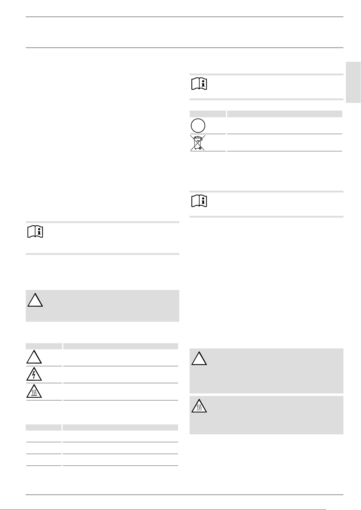
1.1.2 Symbols, type of risk
Symbol Type of risk
!
Injury
Electrocution
Burns
(burns, scalding)
1.2 Other symbols in this documentation
Note
General information is identified by the adjacent symbol.
Read these texts carefully.
Symbol Meaning
!
This symbol indicates that you have to do something. The ac-
tion you need to take is described step by step.
Material losses
(appliance damage, consequential losses and environmental pollution)
Appliance disposal
1.3 Units of measurement
Note
All measurements are given in mm unless stated otherwise.
2. Safety
2.1 Intended use
This sealed unvented (pressurised) appliance is intended for heating domestic hot water. The appliance can supply one or more
draw-off points.
This appliance is intended for domestic use. It can be used safely
by untrained persons. The appliance can also be used in a non-domestic environment, e.g. in a small business, as long as it is used
in the same way.
Any other use beyond that described shall be deemed inappropriate. Observation of these instructions and of instructions for any
accessories used is also part of the correct use of this appliance.
2.2 General safety instructions
DANGER
!
Failure to operate the relief valve easing gear at least
once every six months may result in the water heater
exploding.
Continuous leakage of water from the valve may indicate
a problem with the water heater.
WARNING Burns
During operation, the tap and safety valve can reach
1.1.3 Keywords
KEYWORD Meaning
DANGER Failure to observe this information will result in serious
injury or death.
WARNING Failure to observe this information may result in serious
injury or death.
CAUTION Failure to observe this information may result in non-seri-
ous or minor injury.
www.stiebel-eltron.com SHC 10 AU | SHC 15 AU | 3
temperatures in excess of 60°C.
There is a risk of scalding at outlet temperatures in excess of 43 °C.
Page 4

OPERATION
Appliance description
WARNING Burns
The water in the appliance can be heated to temperatures in excess of 60 °C.
In Australia and New Zealand observe regulations
in accordance with AS/NZS 3500.4.
Install either a tempering valve or thermostatic
mixing valve in all systems intended for personal
hygiene. With this the delivery temperature for personal hygiene outlets must be limited to 50 °C.
WARNING Injury
!
The appliance may be used by children aged8 and older
and persons with reduced physical, sensory or mental
capabilities or a lack of experience and know-how, provided that they are supervised or they have been instructed on how to use the appliance safely and have
understood the resulting risks. Children must never play
with the appliance. Children must never clean the appliance or perform user maintenance unless they are
supervised.
Material losses
!
The user should protect the appliance, the water pipes,
the safety valve and the tap against frost.
Material losses
!
If the drain pipe of the safety valve is sealed, expanding
water can lead to water damage.
Never close the drain pipe.
2.3 Test symbols
See type plate on the appliance.
Installation shall comply with standard AS/NZS 3500.4.
4. Cleaning, care and maintenance
Never use abrasive or corrosive cleaning agents. A damp
cloth is sufficient for cleaning the appliance.
Check the taps regularly. Limescale deposits at the tap out-
lets can be removed using commercially available descaling
agents.
Regularly activate the safety valve to prevent it from becom-
ing blocked, e.g. by limescale deposits.
Have the protective anode checked by a qualified contractor
after the first 2years of operation. The qualified contractor
will then determine the intervals at which it must be checked
thereafter.
Almost every type of water will deposit limescale at high temperatures. This settles inside the appliance and affects both the performance and service life. The heating elements should therefore
be descaled if necessary. A qualified contractor who is aware of
the local water quality will tell you when the next descaling is due.
5. Troubleshooting
Problem Cause Remedy
The appliance does not
supply hot water.
Water can only be
drawn at a reduced
rate.
Loud boiling noises inside the appliance.
Water drips from the
safety valve after
heat-up.
Water drips from the
safety valve continuously.
No power at the
appliance.
The aerator in
the tap is scaled
up or dirty.
The appliance is
scaled up.
The safety valve
is scaled up or
dirty.
The pressure in
the line is above
550 kPa.
Check the plug / fuses in the fuse
box.
Descale / replace the aerator.
Have the appliance descaled by a
qualified contractor.
Switch the appliance off. Depressurise the appliance by disconnecting
it from the power and water supply.
Have the safety valve checked by a
qualified contractor.
Install or readjust pressure reduction valve, set to 550 kPa.
3. Appliance description
The appliance constantly keeps the water content available at the
preset temperature. The appliance switches on automatically as
soon as its temperature falls below the set value.
Subject to season, varying cold water temperatures can result in
different maximum mixed water and outlet volumes.
Note
The appliance is under mains water pressure. The water
volume increases as the cylinder is being heated up. During this process, expansion water drips through the safety
valve. This is a necessary and normal process.
If you cannot remedy the fault, notify your qualified contractor.
To facilitate and speed up your enquiry, please provide the serial
number from the type plate. (000000):
O-No.
F-No.
000000
0000 - 000000
D0000039382
4 | SHC 10 AU | SHC 15 AU www.stiebel-eltron.com
Page 5
ENGLISH
INSTALLATION
Safety
INSTALLATION
6. Safety
Only a qualified contractor should carry out installation, commissioning, maintenance and repair of the appliance.
6.1 General safety instructions
We guarantee trouble-free function and operational reliability only
if original accessories and spare parts intended for the appliance
are used.
6.2 Instructions, standards and regulations
Note
Observe all applicable national and regional regulations
and instructions.
7. Appliance description
The sealed unvented (pressurised) appliance is only suitable for
undersink installation. The appliance is intended for heating cold
water and to supply one or several draw-off points.
The appliance may only be installed with pressure taps and in
conjunction with the safety valve supplied and a non-return valve
in the cold water supply line (see chapter "Installation/ Appliance
description/ Standard delivery").
The safety valve supplied protects the appliance against unacceptable excess pressure. The maximum allowed opening pressure
is 700kPa.
If the water supply pressure exceeds 550kPa, a pressure reducing
valve set to a maximum of 550kPa, and compliant with AS1357.2
and installed in accordance with AS3500.4.2 must be fitted in the
installation.
The enamelled internal steel cylinder is equipped with a protective
anode. The protective anode protects the inner cylinder against
corrosion.
8. Preparations
Water installation
The safety valve supplied and a non-return valve for the cold water
supply line are essential.
8.1 Installation site
Material losses
!
Install the appliance in a room free from the risk of frost.
Material losses
!
Mount the appliance on the wall. The wall must have a
sufficient load-bearing capacity.
Material losses
!
The appliance is only suitable for undersink installation.
The water connections of the appliance point upwards.
Note
Ensure that the appliance is freely accessible for maintenance work.
Always install the appliance vertically and near the draw-off point.
D0000050301
7.1 Standard delivery
The following are delivered with the appliance:
- Wall mounting bracket
- Safety valve G1/2
- Reducer from R3/4 male to G1/2 female
www.stiebel-eltron.com SHC 10 AU | SHC 15 AU | 5
Page 6

INSTALLATION
Installation
9. Installation
9.1 Safety valve installation
Observe local regulations on expansion valves.
Observe the safety valve installation instructions.
Install a non-return valve in the cold water supply line of the
appliance.
1
2
1 Safety valve G1/2
2 Reducer from R3/4 male to G1/2 female
Fit the safety valve together with the reducer at the top in the
centre appliance port.
Attach a drain line to the safety valve.
Size the drain pipe so that water can drain off unimpeded
when the safety valve is fully opened.
Fit the drain pipe of the safety valve with a constant down-
ward slope and in a room free from the risk of frost.
The safety valve drain must remain open to the atmosphere.
Check the safety valve and all fittings for tightness.
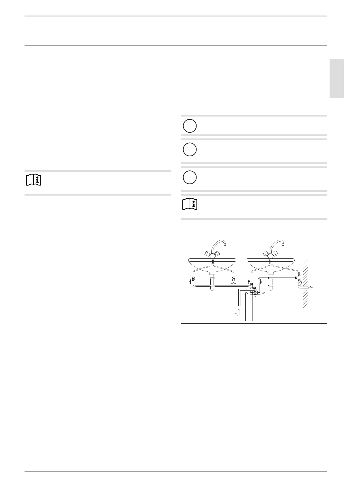
9.3 Water connection
WARNING Burns
The water in the appliance can be heated to temperatures in excess of 60 °C.
In Australia and New Zealand observe regulations
in accordance with AS/NZS 3500.4.
Install either a tempering valve or thermostatic
mixing valve in all systems intended for personal
hygiene. With this the delivery temperature for personal hygiene outlets must be limited to 50 °C.
Material losses
!
Carry out all water connection and installation work in
accordance with regulations.
Material losses
!
Never interchange the water connections.
Observe the maximum permissible pressure (see chapter "In-
stallation/ Specification/ Data table").
Match up the colour coding on the water connections of the
D0000058329
appliance to the tap connections:
- R.h. side blue = "Cold water inlet"
- L.h. side red = "DHW outlet"
Secure the water connections from the tap to the appliance.
Check the entire hydraulic installation for tightness.
Note
Ensure that the water connections are not kinked during
installation. Prevent any tensioning during installation.
9.4 Power supply
9.2 Appliance installation
Mark out the holes to be drilled on the wall (see chapter "In-
stallation / Specification / Dimensions and connections").
Drill the holes and insert suitable rawl plugs.
Secure the wall mounting bracket using suitable screws.
Hang the appliance on the wall mounting bracket.
Note
Surplus cable can be stored in the cable compartment.
WARNING ELECTROCUTION
Carry out all electrical connection and installation work
in accordance with relevant regulations.
WARNING ELECTROCUTION
When permanently connected to the power supply using
a dedicated junction box, the appliance must be able to
be isolated from the mains power supply by an isolator
that disconnects all poles with at least 3mm contact
separation.
WARNING ELECTROCUTION
Ensure that the appliance is earthed.
Material losses
!
The voltage specified on the type plate must match the
mains voltage.
Observe the type plate.
Connection to a freely accessible standard socket
with matching plug
Permanent connection to an appliance junction box
D0000050291
with earth conductor
SHC 10 AU SHC 15 AU
X X
X X
6 | SHC 10 AU | SHC 15 AU www.stiebel-eltron.com
Page 7

ENGLISH
INSTALLATION
Commissioning
10. Commissioning
WARNING ELECTROCUTION
Commissioning may only be carried out by a qualified
contractor in accordance with safety regulations.
10.1 Initial start-up
1. 2.
Either open the DHW valve of the tap or set the lever mixer
tap to "hot" until the water that flows out is free of air
bubbles.
Insert the plug into the standard socket or set the fuse/MCB
in the fuse box.
Check the function of the appliance. Ensure that the tempera-
ture controller switches off.
Check that the safety valve is working correctly.
Check the entire hydraulic installation for tightness.
Note
If you fail to follow the correct sequence (first water, then
power), the high limit safety cut-out of the water heater
will trip.
Proceed as follows:
Make the high limit safety cut-out operational by
pressing the reset button (see chapter "Installation/
Troubleshooting/ Activating the high limit safety
cut-out").
12. Troubleshooting
Fault Cause Remedy
The appliance does
not supply hot water.
D0000049325
The flanged immersion
Loud boiling noises
inside the appliance.
Water drips from the
safety valve after
heat-up.
12.1 Activate high limit safety cut-out
The high limit safety
cut-out has tripped.
The controller is fault y. Replace the combined tem-
heater is faulty.
The appliance is scaled
up.
The safety valve is
scaled up or dirty.
Remedy the cause of the fault.
If necessary, replace the combined temperature controller/
high limit safety cut-out. Make
the high limit safety cut-out
operational by pressing the
reset but ton on the high limit
safety cut-out (see chapter
"Installation/ Troubleshooting/
Activating the high limit safety
cut-out").
perature controller/ high limit
safety cut-out.
Replace the flanged immersion
heater.
Descale the appliance.
Clean/ descale the valve seat.
10.1.1 Appliance handover
Explain the functions of the appliance to the user. Show the
user how to operate the appliance.
Make the user aware of potential dangers, especially the risk
of scalding.
Hand over these instructions and, if applicable, the instruc-
tions for any accessories.
10.2 Recommissioning
See chapter "Installation/ Commissioning/ Initial start-up".
11. Shutdown
Isolate the appliance from the power supply by removing the
plug or by tripping the MCB in the fuse box.
Drain the appliance (see chapter "Installation/ Maintenance/
Draining the appliance").
Open the appliance (see chapter "Installation/ Maintenance/
Opening the appliance").
Press the reset button on the high limit safety cut-out.
Close the appliance cover.
13. Maintenance
WARNING ELECTROCUTION
Before any work on the appliance, disconnect all poles of
the appliance from the power supply.
Dismantle the appliance for maintenance work.
13.1 Checking the safety valve
Check the function of the safety valve regularly.
13.2 Draining the appliance
WARNING Burns
Hot water may escape during the draining process.
Drain the appliance via its connectors.
D0000050292
www.stiebel-eltron.com SHC 10 AU | SHC 15 AU | 7
Page 8

INSTALLATION
Maintenance
13.3 Opening the appliance
Remove the 4 screws from the casing.
Open the appliance cover by pivoting the cover upwards and
then removing it.
Remove the upper insulation semi-shell if required.
Note
The appliance is factory-set to the maximum temperature.
Never change the factory-set temperature setting.
13.5 Removing the protective anode
1
D0000050296
1 Protective anode
Remove the protective anode.
D0000050293
13.6 Fitting the flanged immersion heater and
temperature controller/ high limit safety cutout
13.4 Removing the flanged immersion heater and
temperature controller/ high limit safety cutout
1 2
1 Flanged immersion heater
2 Combined temperature controller/ high limit safety cut-out
Remove the combined temperature controller/ high limit
safety cut-out from the flanged immersion heater.
Remove the flanged immersion heater.
Insert the flanged immersion heater into the cylinder aper-
ture well as far as it will go.
Push the combined temperature controller/ high limit safety
D0000050295
cut-out into the flanged immersion heater as far as it will go.
Align the flanged immersion heater and the combined tem-
perature controller/ high limit safety cut-out in accordance
with the diagram.
Turn the shaft of the temperature controller anti-clockwise as
far as it will go.
13.7 Descaling the appliance
Material losses
!
Never treat the protective anode with descaling agents.
D0000050294
Remove the flanged immersion heater.
Remove the protective anode.
Carefully tap the heating element to remove coarse limescale
deposits.
Immerse the heating element up to the flange plate in desca-
ling agent.
8 | SHC 10 AU | SHC 15 AU www.stiebel-eltron.com
Page 9

ENGLISH
INSTALLATION
Specication
13.8 Checking the protective anode
Check the protective anode for the first time 2 years after
installation. This requires removal of the flanged immersion
heater. Replace the protective anode if consumed.
Decide the intervals in which further checks should be car-
ried out.
13.9 Replacing the power cable
The power cable must only be replaced by a qualified contractor
with an original spare part.
13.10 Checking the earth conductor
Check the earth conductor across a water connector and the
earth conductor contact of the power cable.
14. Specification
14.1 Dimensions and connections
a20
c01
i13
a10
a30
80
14.2 Wiring diagram
1/N/PE ~ 220-240V
1 2
A B
L
N PE
14.3 Heat-up diagram
The heat-up period depends on the degree of scaling and residual
heat. For the heat-up time for a cold water supply at 10 °C and a
maximum temperature setting, see the diagram.
D0000035810
c06
c01
100
SHC 10 AU SHC 15 AU
a10 Appliance Height mm 498 523
a20 Appliance Width mm 280 320
a30 Appliance Depth mm 270 318
c01 Cold water Inlet
Top clearance mm 26.5 23
c06 DHW outlet Male thread G 1/2 A G 1/2 A
i13 Wall mounting
bracket
Horizontal hole
Male thread G 1/2 A G 1/2 A
Height mm 320 342
mm 140 200
spacing
40
35
30
25
20
15
10
5
0
35 40 45 50 55 60 65
1
2
x Temperature in °C
y Duration in min
1 15lappliance
D0000050298
2 10lappliance
14.4 Country-specific approvals and certifications
The test symbols can be seen on the type plate.
14.5 Extreme operating and fault conditions
In the case of faults, a peak temperature of up to 99 °C may briefly
occur in the system.
D0000039377
www.stiebel-eltron.com SHC 10 AU | SHC 15 AU | 9
Page 10

INSTALLATION
Specication
14.6 Data table
SHC 10 AU SHC 15 AU
235002 235001
Hydraulic data
Nominal capacity l 10 15
Mixed water volume at 40°C (IEC 60379) l 15.3 23
Electrical data
Rated voltage V 220 230 240 220 230 240
Rated output kW 1.4 1.5 1.6 1.4 1.5 1.6
Rated current A 6.2 6.5 6.8 6.2 6.5 6.8
MCB/fuse rating A 10 10 10 10 10 10
Phases 1/N/PE 1/N/PE
Frequency Hz 50/60 50/60
Application limits
Max. permissible pressure MPa 0.7 0.7
Min. water inlet pressure MPa 0.1 0.1
Max. water inlet pressure MPa 0.6 0.6
Max. flow rate l/min 10 10
Energy data
Standby energy consumption/24h at 65°C kWh 0.5 0.53
Versions
IP rating IP24 D IP24 D
Type of installation Undersink Undersink
Type Pressurised Pressurised
Internal cylinder material Steel, enamelled Steel, enamelled
Thermal insulation material Polystyrene Polystyrene
Casing material Plastic Plastic
Colour White White
Dimensions
Depth mm 270 318
Height mm 498 523
Width mm 280 320
Weights
Weight kg 7.2 9.0
10 | SHC 10 AU | SHC 15 AU www.stiebel-eltron.com
Page 11

ENGLISH
:$55$17< | ENVIRONMENT AND RECYCLING
8BSSBOUZ
The guarantee conditions of our German companies do not
apply to appliances acquired outside of Germany. In countries
where our subsidiaries sell our products a guarantee can only
be issued by those subsidiaries. Such guarantee is only granted if the subsidiary has issued its own terms of guarantee. No
other guarantee will be granted.
We shall not provide any guarantee for appliances acquired in
countries where we have no subsidiary to sell our products.
This will not aect warranties issued by any importers.
Environment and recycling
We would ask you to help protect the environment. After use,
dispose of the various materials in accordance with national
regulations.
Stiebel Eltron Warranty for Water Heaters – Models SHC10AU
and SHC15AU
Who gives the warranty
1. The warranty is given by Stiebel Eltron (Aust) Pty Ltd
(A.B.N. 82066271083) of 6 Prohasky Street, Port Melbourne, Victoria, 3207 (“we”, “us” or “our”).
The warranty
2. This warranty applies to Stiebel Eltron Water Heaters –
Models SHC10AU and SHC15AU (the “unit”) manufactured after 1 June 2013.
3. Subject to the warranty exclusions we will repair or replace, at our absolute discretion, a faulty component in
your unit free of charge if it fails to operate in accordance
with its specifications during the warranty period.
4. If we repair or replace a faulty component to your unit
under this warranty, the warranty period is not extended
from the time of the repair or replacement.
5. The warranty period commences on the date of completion
of the installation of the unit. Where the date of completion of installation is not known, then the warranty period
will commence 2 months after the date of manufacture.
6. The warranty period for a unit is shown in the table below.
Component Warranty period
Cylinder 7 years from the date of completion of the installa-
Parts & labour 3 years from the date of completion of the installa-
.
PTR valve 1 year from the date of completion of the installa-
Your entitlement to make a warranty claim
You are entitled to make a warranty claim if:
7.
7.1. you own the unit or if you have the owner’s consent to
represent the owner of the unit;
7.2. you contact us within a reasonable time of discovering the
problem with the unit;
How you make a warranty claim
8. To make a warranty claim you must provide us with the
following information:
8.1. The model number of the unit;
tion of the unit.
tion of the unit.
tion of the unit.
www.stiebel-eltron.com SHC 10 AU | SHC 15 AU | 11
Page 12

GUARANTEE | ENVIRONMENT AND RECYCLING
GUARANTEE
ENVIRONMENT AND RECYCLING
8.2. A description of the problem with the unit;
8.3. The name, address and contact details (such as phone
number and e-mail address) of the owner;
8.4. The address where the unit is installed and the location
(e.g. in laundry);
8.5. The serial number of the unit;
8.6. The date of purchase of the unit and the name of the seller
of the unit;
f) foreign matter in the water supply, such as sludge or
sediment;
g) corrosive elements in the water supply;
h) accidental damage;
i) act of God, including damage by flood, storm, fire,
lightning strike and the like;
j) excessive water pressure, negative water pressure (par-
tial vacuum) or water pressure pulsation.
11.6. The unit was damaged before it was installed e.g. it was
damaged in transit.
8.7. The date of installation of the unit;
8.8. A copy of the certificate of compliance when the unit was
installed.
9. The contact details for you to make your warranty claim
are:
Name:
Address:
Telephone:
Contact person:
E-mail:
Stiebel Eltron (Aust) Pty Ltd
6 Prohasky Street, Port Melbourne, Victoria,
3207
1800 153 351 (8.00am to 5.00pm AEST
Monday to Friday)
Customer Service Representative
service@stiebel.com.au
10. We will arrange a suitable time with you to inspect and
test the unit.
Warranty exclusions
11. We may reject your warranty claim if:
11.1. The unit was not installed by registered and qualified
tradespeople.
11.2. The unit was not installed and commissioned:
a) in Australia;
b) in accordance with the Operating and Installation
Guide; and
c) in accordance with the relevant statutory and local
requirements of the State or Territory in which the unit
is installed.
11.3. The unit has not been operated or maintained in accordance with the Operating and Installation Guide.
11.4. The unit does not bear its original Serial Number or Rating
Label.
11.5. The unit was damaged by any or any combination of the
following:
a) normal fair wear and tear;
b) connection to an incorrect water supply;
c) connection to water from a bore, dam or swimming
pool;
d) connection to an incorrect power supply;
e) connection to faulty equipment, such as damaged
valves;
11.7. An unauthorised person has modified, serviced, repaired
or attempted to repair the unit without our consent.
11.8. Non genuine parts other than those manufactured or approved by us have been used on the unit.
12. We may charge you:
12.1. for any additional transport costs if the unit is installed
more than 30 kilometres from our closest authorised service technician.
12.2. for the extra time it takes our authorised service technician
to access the unit for inspection and testing if it is not sited
in accordance with the Operating and Installation Guide
and not readily accessible for inspection.
12.3. for any extra costs of our authorised service technician to
make the unit safe for inspection.
13. You must ensure that access to the unit by our authorised
service technician is safe and free from obstruction.
14. Our authorised service technician may refuse to inspect
and test the unit until you provide safe and free access to
it, at your cost.
15. If we reject your warranty claim in accordance with clause
12, we may charge you for our authorised service technician’s labour costs to inspect and test the unit.
16. In order to properly test the unit we may remove it to another location for testing.
Australian Consumer Law
17. Our goods come with guarantees that cannot be excluded
under the Australian Consumer Law. You are entitled to a
replacement or refund for a major failure and compensation for any other reasonably foreseeable loss or damage.
You are also entitled to have the goods repaired or replaced if the goods fail to be of acceptable quality and the
failure does not amount to a major failure.
18. The Stiebel Eltron warranty for the unit is in addition to any
rights and remedies you may have under the Australian
Consumer Law.
12 | SHC 10 AU | SHC 15 AU www.stiebel-eltron.com
Page 13

ENGLISH
NOTES
www.stiebel-eltron.com SHC 10 AU | SHC 15 AU | 13
Page 14

NOTES
14 | SHC 10 AU | SHC 15 AU www.stiebel-eltron.com
Page 15

ENGLISH
NOTES
www.stiebel-eltron.com SHC 10 AU | SHC 15 AU | 15
Page 16

Deutschland
STIEBEL ELTRON GmbH & Co. KG
Dr.-Stiebel-Straße 33 | 37603 Holzminden
Tel. 05531 702-0 | Fax 05531 702-480
info@stiebel-eltron.de
www.stiebel-eltron.de
Verkauf Tel. 05531 702-110 | Fax 05531 702-95108 | info-center@stiebel-eltron.de
Kundendienst Tel. 05531 702-111 | Fax 05531 702-95890 | kundendienst@stiebel-eltron.de
Ersatzteilverkauf Tel. 05531 702-120 | Fax 05531 702-95335 | ersatzteile@stiebel-eltron.de
Irrtum und technische Änderungen vorbehalten! | Subject to errors and technical changes! | Sous réserve
d‘erreurs et de modifications techniques! | Onder voorbehoud van ver
g
issingen en technische wijzigingen! |
Salvo error o modificación técnica! | Excepto erro ou alteração técnica | Zastrzeżone zmian
y
techniczne i
ewentualne błędy | Omyly a technické změny jsou vyhrazeny! | A muszaki változtatások és tévedések jogát
fenntartjuk! |
Отсутствие ошибок не гарантируется. Возможны технические изменения.
| Chyby a
technické zmeny sú vyhradené! Stand 9046
Australia
STIEBEL ELTRON Australia Pty. Ltd.
6 Prohasky Street | Port Melbourne VIC 3207
Tel. 03 9645-1833 | Fax 03 9645-4366
info@stiebel.com.au
www.stiebel.com.au
Austria
STIEBEL ELTRON Ges.m.b.H.
Eferdinger Str. 73 | 4600 Wels
Tel. 07242 47367-0 | Fax 07242 47367-42
info@stiebel-eltron.at
www.stiebel-eltron.at
Belgium
STIEBEL ELTRON bvba/sprl
't Hofveld 6 - D1 | 1702 Groot-Bijgaarden
Tel. 02 42322-22 | Fax 02 42322-12
info@stiebel-eltron.be
www.stiebel-eltron.be
China
STIEBEL ELTRON (Guangzhou) Electric
Appliance Co., Ltd.
Rm 102, F1, Yingbin-Yihao Mansion, No. 1
Yingbin Road
Panyu District | 511431 Guangzhou
Tel. 020 39162209 | Fax 020 39162203
info@stiebeleltron.cn
www.stiebeleltron.cn
Czech Republic
STIEBEL ELTRON spol. s r.o.
K Hájům 946 | 155 00 Praha 5 - Stodůlky
Tel. 251116-111 | Fax 235512-122
info@stiebel-eltron.cz
www.stiebel-eltron.cz
Finland
STIEBEL ELTRON OY
Kapinakuja 1 | 04600 Mäntsälä
Tel. 020 720-9988
info@stiebel-eltron.fi
www.stiebel-eltron.fi
France
STIEBEL ELTRON SAS
7-9, rue des Selliers
B.P 85107 | 57073 Metz-Cédex 3
Tel. 0387 7438-88 | Fax 0387 7468-26
info@stiebel-eltron.fr
www.stiebel-eltron.fr
Hungary
STIEBEL ELTRON Kft.
Gyár u. 2 | 2040 Budaörs
Tel. 01 250-6055 | Fax 01 368-8097
info@stiebel-eltron.hu
www.stiebel-eltron.hu
Japan
NIHON STIEBEL Co. Ltd.
Kowa Kawasaki Nishiguchi Building 8F
66-2 Horikawa-Cho
Saiwai-Ku | 212-0013 Kawasaki
Tel. 044 540-3200 | Fax 044 540-3210
info@nihonstiebel.co.jp
www.nihonstiebel.co.jp
Netherlands
STIEBEL ELTRON Nederland B.V.
Daviottenweg 36 | 5222 BH 's-Hertogenbosch
Tel. 073 623-0000 | Fax 073 623-1141
info@stiebel-eltron.nl
www.stiebel-eltron.nl
Poland
STIEBEL ELTRON Polska Sp. z O.O.
ul. Działkowa 2 | 02-234 Warszawa
Tel. 022 60920-30 | Fax 022 60920-29
biuro@stiebel-eltron.pl
www.stiebel-eltron.pl
Russia
STIEBEL ELTRON LLC RUSSIA
Urzhumskaya street 4,
building 2 | 129343 Moscow
Tel. 0495 7753889 | Fax 0495 7753887
info@stiebel-eltron.ru
www.stiebel-eltron.ru
Slovakia
TATRAMAT - ohrievače vody s.r.o.
Hlavná 1 | 058 01 Poprad
Tel. 052 7127-125 | Fax 052 7127-148
info@stiebel-eltron.sk
www.stiebel-eltron.sk
Switzerland
STIEBEL ELTRON AG
Industrie West
Gass 8 | 5242 Lupfig
Tel. 056 4640-500 | Fax 056 4640-501
info@stiebel-eltron.ch
www.stiebel-eltron.ch
Thailand
STIEBEL ELTRON Asia Ltd.
469 Moo 2 Tambol Klong-Jik
Amphur Bangpa-In | 13160 Ayutthaya
Tel. 035 220088 | Fax 035 221188
info@stiebeleltronasia.com
www.stiebeleltronasia.com
United Kingdom and Ireland
STIEBEL ELTRON UK Ltd.
Unit 12 Stadium Court
Stadium Road | CH62 3RP Bromborough
Tel. 0151 346-2300 | Fax 0151 334-2913
info@stiebel-eltron.co.uk
www.stiebel-eltron.co.uk
United States of America
STIEBEL ELTRON, Inc.
17 West Street | 01088 West Hatfield MA
Tel. 0413 247-3380 | Fax 0413 247-3369
info@stiebel-eltron-usa.com
www.stiebel-eltron-usa.com
4<AMHCMO=bhfedi>
A 317543-39103-9070
 Loading...