

Page 1

Operation and Installation
Simply the Best
Guía De Funcionamiento e Instalación
Mode D’emploi et Manuel D’installation
Wall-Mounted Infrared Room Heater | Calefactor Infrarrojo Montado en la Pared |
Chauffage Infrarouge à Montage Mural
» SunWarmth™ CIR 150-1 I
» SunWarmth™ CIR 150-1 O
» SunWarmth™ CIR 200-2 O
» SunWarmth™ CIR 400-2 O
3154365
Conforms to
ANSI/UL 1278 or 2021
Certified to
CAN/CSA C22.2 No.46
Page 2

CONTENTS | OPERATION
IMPORTANT INSTRUCTIONS
OPERATION
1. Important instructions �����������������������������������������2
1.1 Document information �������������������������������������������� 3
1.2 Key to symbols ������������������������������������������������������ 3
2. Safety ������������������������������������������������������������4
2.1 Intended use ��������������������������������������������������������� 4
2.2 Safety information ������������������������������������������������� 4
2.3 ETL / UL / CSA designation ��������������������������������������� 4
3. Register your product ������������������������������������������ 5
4. Appliance description ������������������������������������������5
5. Operation �������������������������������������������������������5
5.1 Starting the heater ������������������������������������������������� 5
5.2 Shutting down the heater����������������������������������������� 5
6. Cleaning, care and maintenance ������������������������������ 5
6.1 Maintenance ��������������������������������������������������������� 5
6.2 Cleaning �������������������������������������������������������������� 5
INSTALLATION
7. Safety ������������������������������������������������������������6
7.1 General safety instructions ��������������������������������������� 6
7.2 Instructions, standards and regulations ����������������������� 6
8. Appliance description ������������������������������������������6
8.1 Standard delivery ��������������������������������������������������� 6
9. Installation ������������������������������������������������������6
9.1 Project design considerations & guidelines ������������������� 6
9.2 Recommended mounting and coverage specifications ����� 7
9.3 General installation instructions �������������������������������� 7
9.4 Locating the heater������������������������������������������������� 8
9.5 Minimum required clearances to surfaces and
combustibles �������������������������������������������������������� 8
9.6 Mounting the heater ����������������������������������������������� 8
9.7 Power supply ������������������������������������������������������� 10
9.8 Heat lamp replacement ������������������������������������������ 12
10. Appliance handover ������������������������������������������ 19
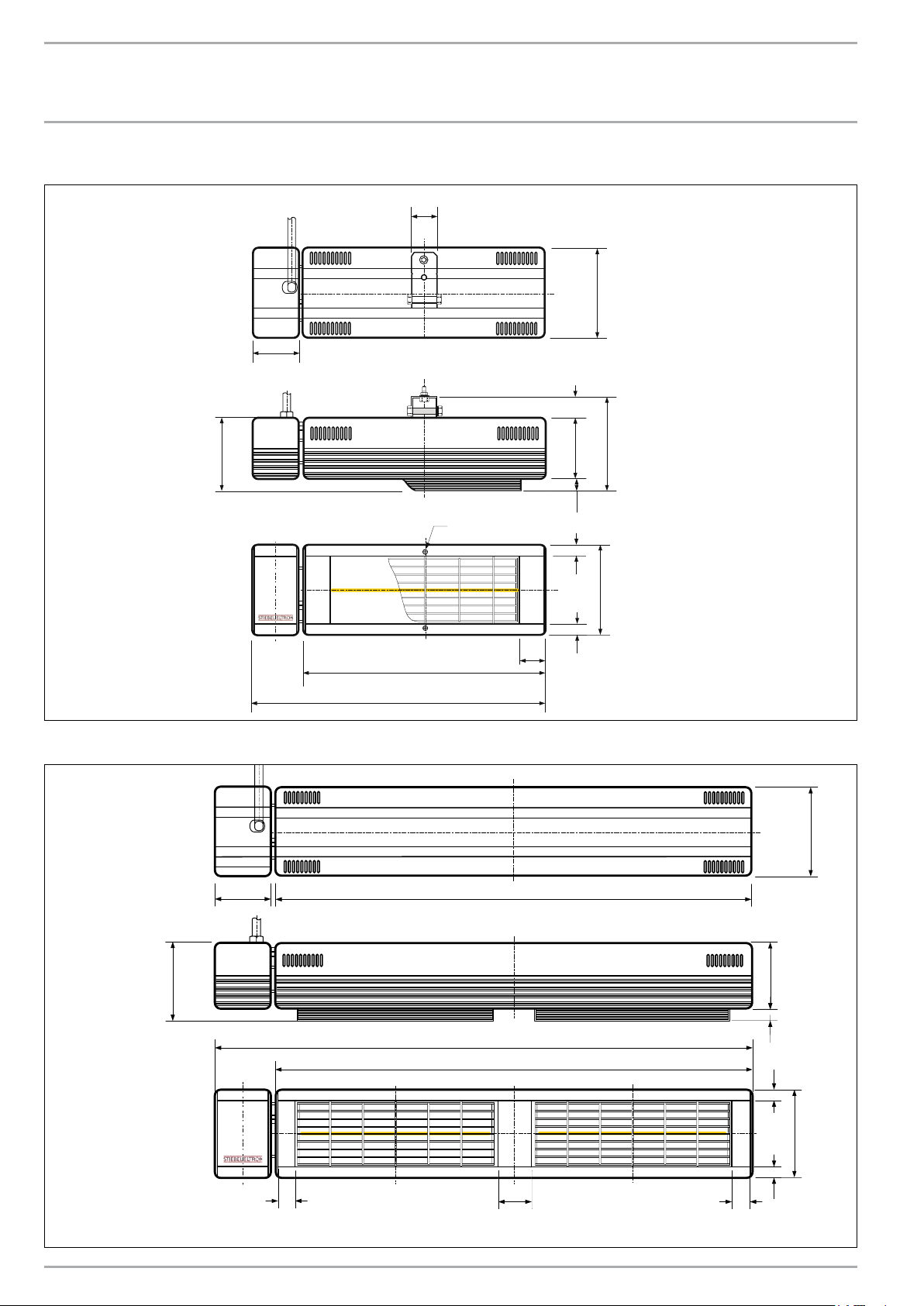
11. Specification ��������������������������������������������������� 19
11.1 Dimensions - CIR 150-1 I ����������������������������������������� 19
11.2 Dimensions - CIR 150-1 O & CIR 200-2 O ���������������������� 20
11.3 Dimensions - CIR 400-2 O ���������������������������������������� 20
11.4 Specification table ������������������������������������������������� 21
12. Spare parts ���������������������������������������������������� 21
13. What to do if... ������������������������������������������������ 21
WARRANTY AND CUSTOMER SERVICE
ENVIRONMENT AND RECYCLING
1. IMPORTANT INSTRUCTIONS
SAVE THESE INSTRUCTIONS
When using electrical appliances, basic precautions should always
be followed to reduce the risk of fire, electric shock, injury to
persons or death, and property damage including the following:
1. This heater must be installed only by a qualified electrician.
Read and understand all instructions before installing, using or
servicing this heater. Improper installation, operation, adjustment,
alteration, service or maintenance can result in the risk of fire and
electrical shock, and may cause property damage, injury or death.
2. This heater is hot when in use. To avoid burns, do not let bare
skin touch hot surfaces. Keep electrical cords and combustible
materials, such as furniture, pillows, bedding, papers, clothes,
etc. and curtains at least 3 feet (1 m) from the front of the heater
and keep them at least 3 feet (1 m) away from the sides and rear.
3. Extreme caution is necessary when any heater is used by or
near children or invalids.
4. Never leave the heater unattended during operation. Unplug
120 V models or turn off circuit breaker(s) on 240 V models if not
in use.
5. Do not operate any heater with a damaged cord or plug, or after
the heater malfunctions, or if it has been dropped or damaged
in any manner. Return heater to an authorized service facility for
examination, electrical or mechanical adjustment, or repair.
6. These heaters are not for use in bathrooms, laundry areas, and
similar indoor locations. Never locate heater where it may fall into
a bathtub or other water container.
7. MODEL “CIR 150-1 I” IS FOR INDOOR USE ONLY. Do not use
this model outdoors or in wet environments. Models CIR 150-1
O, CIR 200-2 O, and CIR 400-2 O may be used outdoors or in wet
environments.
8. Do not run cord under carpeting. Do not cover cord with throw
rugs, runners, or the like. Arrange cord away from traffic areas
where it will not be tripped over.
9. Arrange the cord at the side and back of the heater - do not
allow cord to drape over the heater.
10. To disconnect heater remove plug from outlet (120 V models)
or switch off at power source (240 V models).
11. 120 V models CIR 150-1 I and CIR 150-1 O must be connected
to a 120 V outlet that is properly grounded and controlled by a
timer switch.
12. 240 V models must be hard wired to a circuit that is properly
grounded and controlled by a timer switch. Copper wire is
required.
13. Do not insert or allow foreign objects to enter the heater or any
ventilation or exhaust opening as this may cause an electric shock,
fire, or damage the heater. Death, personal injury or property
damage could result.
14. To prevent a possible fire, do not block air intakes or exhaust
in any manner. Do not use on a soft surface, like a bed, where
openings may become blocked.
15. Use this heater only as described in this manual. Any other
use not recommended by the manufacturer may cause fire, electric
shock, and death or injury to persons and property damage.
16. With 120 V models, avoid the use of an extension cord
because the extension cord may overheat and cause a risk of fire.
IMPORTANT: However, if you have to use an extension cord, the
cord shall be No. 14 AWG minimum size and rated for not less
than 1875 watts.
2 |SUNWARMTH™ CIR INFRARED HEATER WWW.STIEBEL-ELTRON-USA.COM
Page 3

OPERATION
IMPORTANT INSTRUCTIONS
17. Do not touch an operating heater or live parts - burns, electric
shock and death or personal injury can result.
18. All CIR models must be installed on a timer or timer switch.
Consult local electrician/installer for installation details.
19. Do not adjust the heater on the swivel bracket during operation.
Allow heater to completely cool before making any adjustment to
the heater position.
20. Do not stare at the heater lamp - damage to your eyes could
occur.
21. After use, allow the heater to cool down before touching,
moving, or storing.
22. These instructions belong with the heater for ready reference.
Keep this manual in a safe place near the heater.
1.1 Document information
The chapter Operation is intended for users and qualified installers.
The chapter Installation is intended for qualified installers.
Read these instructions carefully before using the
appliance and retain them for future reference. Pass
on the instructions to any new users.
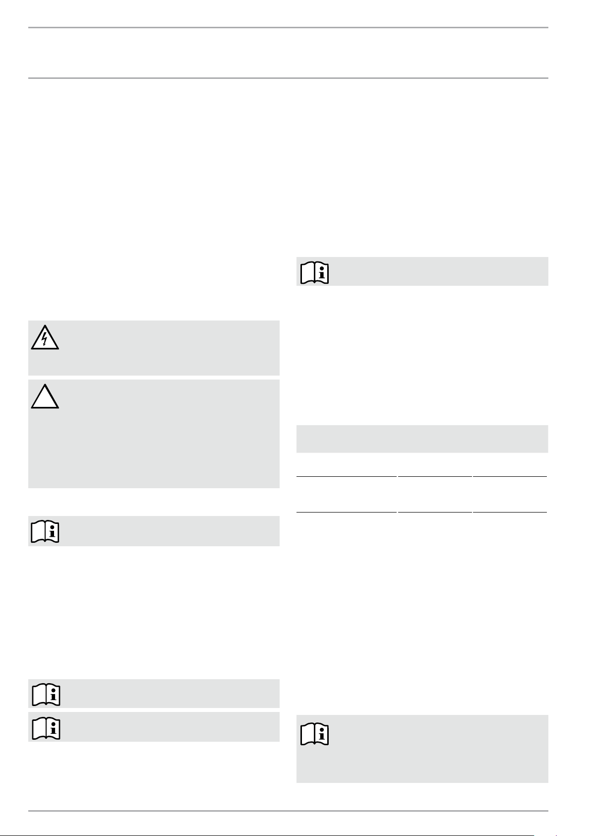
1.2 Key to symbols
1.2.1 Layout of safety information
Safety information comprises a warning symbol, a keyword
text with information. Safety information is printed on a grey
background.
Example:
1.2.3 Text symbols and layout in this documentation
Read the text next to this “»” symbol carefully.
» The "»" symbol indicates that you should do something. The
action you need to take is described step by step.
—Passages with the "
1.2.4 Information on the appliance
Never cover the appliance
–" symbol show you lists of items.
1.2.5 Units of measurement
The dimensions in this document are given in in. / mm.
Any alternative units of measurements are specified
accordingly.
ENGLISH
1 2 3
DANGER Electrocution
Install the appliance in such a way that control
equipment...
4
1 Symbol (see section 1.2.3 on warning symbols)
2 Keyword (see section 1.2.2 on keywords)
3 Description (see section 1.2.3 on warning symbols)
4 Information text
1.2.2 Keywords
KEYWORD Description
DANGER
WARNING
CAUTION
The keyword DANGER indicates information which must be
observed, otherwise serious injury or death will result.
The keyword WARNING indicates information that must be
observed, otherwise serious injury or death may result.
The keyword CAUTION indicates information that must be
observed, otherwise relatively serious or light injuries may
result.
WWW.STIEBEL-ELTRON-USA.COM SUNWARMTH™ CIR INFRARED HEATER| 3
Page 4

OPERATION
SAFETY
2. Safety
Minimum required clearances to surfaces and combustibles
2.1 Intended use
This appliance is designed to heat living areas. Model CIR 150-1
I is for indoor use only. Models CIR 150-2 O, CIR 200-2 O and CIR
400-2 O are for outdoor or indoor use.
Any other use beyond that described shall be deemed
inappropriate. Correct use of this appliance also includes following
all instructions in this manual. Any modifications or conversions
to the appliance void all warranty rights.
2.2 Safety information
Only operate the appliance when fully installed by a licensed
electrician and with all safety equipment fitted.
WARNING Fire
Never operate this appliance ...
— in rooms where the appliance is at risk of fire or
explosion as a result of chemicals, dust, gases or
vapors.
— in the direct proximity of pipes or receptacles that
carry or contain flammable or explosive materials.
— if work such as laying cables, grinding or sealing
is carried out in the installation room.
— if sprays, floor polish or similar products
containing gasoline are used. Vent the room
sufficiently before heating.
— if the minimum clearances to adjacent object
surfaces are not maintained, for example to
furniture, net curtains, curtains, textiles or other
flammable materials (for minimum clearances, see
drawing above).
WARNING Fire
Never operate this appliance ...
— if an appliance component is damaged, the
appliance has fallen over or already had a fault.
WARNING Injury
Where children or persons with limited physical,
sensory or mental capabilities are allowed to control
this appliance, ensure that this will only happen under
supervision or after appropriate instructions by a
person responsible for their safety.
Children must be supervised and instructed to ensure
that they never play with the appliance.
WARNING Fire
Never place any flammable, combustible or insulating
objects or materials, such as laundry, blankets,
magazines, containers with floor polish or petroleum
products, spray cans or similar on the appliance or in
direct proximity to it.
WARNING Fire
Never leave the heater unattended during operation.
Heater must be installed on a timer switch. Unplug
120 V models or turn off circuit breaker(s) on 240 V
models if not in use.
4 |SUNWARMTH™ CIR INFRARED HEATER WWW.STIEBEL-ELTRON-USA.COM
Page 5

OPERATION
!
REGISTER YOUR PRODUCT
WARNING Electrocution
Always disconnect the heater from the power source
prior to servicing. Failure to do so may result in serious
bodily injury or death.
Do not use or locate the appliance where it could fall
into a bathtub or other water container.
WARNING Burns
The surfaces of the appliance casing become hot
during operation. Do not touch this appliance while
in operation. Allow to completely cool after use and
before touching.
CAUTION Overheating
Never cover the appliance
2.3 ETL / UL / CSA designation
The ETL / UL designation shows that the appliance meets all
essential requirements according to ANSI/UL 1278 or 2021 and
CAN/CSA C22.2 No.46.
2.3.1 Type label
See type plate. The type plate is located on the top in the center
of the exterior of the appliance.
O, CIR 200-2 O, and CIR 400-2 are also suitable for spot heating
outdoor living areas, for example, patios, balconies and decks.
The radiant heater casing is made of aluminum. The protective
grill and screws are made from stainless steel.
5. Operation
WARNING Fire
Never leave the heater unattended during operation.
Heater must be installed on a timer switch. Unplug
120 V models or turn off circuit breaker(s) on 240 V
models if not in use.
5.1 Starting the heater
» For 120 V models, plug the unit into a grounded electrical
outlet connected to a timer switch. Set timer switch for desired
operating time.
» For 240 V models, turn on the circuit breaker(s) the unit is
connected to. Set timer switch for desired operating time.
5.2 Shutting down the heater
» For 120 V models, turn off unit at timer switch and unplug the
unit’s cord from the wall outlet.
» For 240 V models, turn off unit at timer switch and power at the
circuit breaker panel.
ENGLISH
3. Register your product
You must register this product within 90 days
of purchase on our web site in order to activate
any standard warranty or to be eligible for
the extended warranty. Go to our website at:
www.stiebel-eltron-usa.com and click on “Register
Your Product.”
Before beginning the registration process, we suggest that
you gather the necessary information as follows:
Type, Example: CIR 150-1 I (from the label that is on the top of
the unit in the center)
Number listed after “Nr.”
Place of Purchase
Purchase Date
First & Last Name
Email address
Physical Address
Phone Number
If you have any questions concerning the registration process
or warranty options, please contact Stiebel Eltron USA directly at (800)-582-8423.
4. Appliance description
The appliance is a radiant heater that uses short-wave infrared
light. It is designed to heat objects, not the air in the space. It is
designed for installation on a wall or post.
All models are suitable as a spot heating system for indoor
living areas such as garages or workshops, or for livestock.
Note: Model CIR 150-1 I is for indoor use only! Models CIR 150-1
6. Cleaning, care and maintenance
WARNING
Before cleaning, make sure the power has been turned
off at the circuit breaker panel or unplugged from the
wall outlet, and that the heating element of the heater
is cool. Ensure power remains disconnected during
entire installation. Failure to do so could result in
serious burns, electrocution, serious bodily injury, or
death.
6.1 Maintenance
» Inspect the heater and cord prior to each use.
» Clean any accumulation of dust or dirt from surfaces and in
particular from the reflector and any air openings in the heater
body (refer to “Cleaning,” section 6.2, below).
» Inspect the electrical cord and plug for damage or fraying:
- Do not operate the heater with a damaged cord or plug.
- Have damaged parts replaced by a qualified electrician.
» Any damaged parts or components must be repaired or replaced
prior to operation.
6.2 Cleaning
CAUTION Fire
Never spray cleaning spray into the reflector or any
openings.
Ensure that no moisture can enter the appliance.
- Before cleaning, disconnect the heater from the power supply
and allow to cool.
- Do not touch the heat lamp with your fingers - oil from your skin
will damage the lamp.
- To clean the heater surface, reflector, and air inlets: Use only a
dry or damp cloth or low pressure air stream (computer ‘duster’
in a can).
WWW.STIEBEL-ELTRON-USA.COM SUNWARMTH™ CIR INFRARED HEATER| 5
Page 6
INSTALLATION
!
SAFETY
- Do not use any abrasive or caustic cleaning agents.
- Never immerse the appliance in water! Danger to life!
- If a heater is exposed to water beyond the intended use of
outdoor models, have a qualified electrician inspect and repair
the heater prior to use.
- As part of regular maintenance, we recommend also having the
control components checked. The safety and control components
should be checked by a contractor no more than ten years after
commissioning.
7. Safety
Only qualified contractors should carry out installation,
commissioning, maintenance and repair of the appliance.
7.1 General safety instructions
We guarantee trouble-free function and operational reliability
only if the original accessories and spare parts intended for the
appliance are used.
DANGER Electrocution
If you mount the appliance on the wall, do so in such
a way that control equipment cannot be touched by a
person in the bath or shower.
CAUTION
— Observe the minimum clearances to adjacent
object surfaces (for minimum clearances see
section 9.5, pg. 8).
— Never install the appliance directly below a wall
socket.
— Ensure that the power cable is not in contact with
any appliance components.
7.2 Instructions, standards and regulations
—Provide wind breaks wherever possible
—“Spot heating” comfort is most effective if people are
heated from at least two sides
—Available mounting height for heaters at the project site
9.1.2 Indoor application:
—“Space heat” the entire structure (accurate heat loss
calculation required. For assistance contact Stiebel Eltron at
800-582-8423 or info@stiebel-eltron-usa.com), or
—“Spot heat” only part of a cold indoor area
— The activity level of the people: seated at rest, hard physical
labor, etc.
9.1.3 Outdoor application:
NOTE: MODEL “CIR 150-1 I” IS FOR INDOOR USE ONLY!
—Any area heated outdoors is “spot heat”
— Models “CIR 150-1 O”, “CIR 200-2 O”, and “CIR 400-2 O” are
for indoor or outdoor use
» Desired temperature rise:
— In what seasons is comfort required and what is the outside
design temperature?
— Then what temperature rise is desired for comfort? (10°,
15°, 20°, 25°?)
» Calculate the required input to get the desired average
temperature rise:
Input Required per Area per Degree Comfort Temperature Rise
Outdoor heating
(up to 10 mph wind)
Indoor spot heating
(protected area, low
air movement)
Heat density
per degree F
W/(ft2)/°F
2
0.75
Heat density
per degree C
W/(m2)/°C
40
14
Observe all applicable national and regional regulations
and instructions.
8. Appliance description
8.1 Standard delivery
—Heater unit
—Wall mounting bracket including fixing screws, locking
washers and nut
9. Installation
9.1 Project design considerations & guidelines
NOTE: All CIR Infrared Heaters must be installed on a
timer or timer switch.
NOTE: Refer to section 9.5, pg. 8 regarding the
minimum required clearances.
The size and quantity of heaters (amount of heat input) required
over an area to provide comfort is affected by the following factors:
9.1.1 General:
—Amount of air movement in the area: “wind chill” requires
additional heat input
» Input formula = Site Length x Site Width x Temperature Rise x
Heat Density per Degree
Example:
—Outdoor patio: 30 feet long by 10 feet wide
—Desired temperature rise: 20°F (average over the area)
—30 x 10 x 20 x 2 = 12,000 Watts total input required
Compare the values of the available mounting height and area
dimensions at the project site to the recommended mounting
heights, length and width of coverage area, and typical average
heat distribution in section 9.2 (page 6).
Layout:
—Space the heaters uniformly around the perimeter (and if
required, in the center or throughout the area) to provide
sufficient heat density to accomplish the desired temperature
rise or spot heat only specific locations within the area.
—Provide heat from at least two sides wherever possible
NOTE: The design information presented here is
intended as a guideline. The accuracy of determining
or estimating all factors above will affect performance
and satisfaction. Air movement in particular will
affect comfort.
6 |SUNWARMTH™ CIR INFRARED HEATER WWW.STIEBEL-ELTRON-USA.COM
Page 7

INSTALLATION
INSTALLATION
9.2 Recommended mounting and coverage specifications
ENGLISH
H
Model Wattage
CIR 150-1 I, CIR 150-1 O 1500 W Minimum: 7′ (2.1 m)
CIR 200-2 O 2000 W Minimum: 8′ (2.4 m)
CIR 400-2 O 4000 W Minimum: 10′ (3.0 m)
Mounting
height
Maximum: 8′ (2.4 m)
Maximum: 9′ (2.7 m)
Maximum: 11′ 6″ (3.5 m)
A
Length
heated
8′ 10″ (2.7 m)
9′ 10″ (3.0 m)
9′ 10″ (3.0 m)
11′ 2″ (3.4 m)
11′ 10″ (3.6 m)
13′ 5″ (4.1 m)
Dimensions of area heated
B
Width heated
close to heater
8′ 6″ (2.6 m)
9′ 2″ (2.8 m)
9′ 2″ (2.8 m)
9′ 10″ (3.0 m)
11′ 2″ (3.4 m)
14′ 1″ (4.3 m)
C
Width heated
far from heater
16′ 1″ (4.9 m)
18′ 1″ (5.5 m)
18′ 1″ (5.5 m)
20′ (6.1 m)
23′ (7.0 m)
27′ 7″ (8.4 m)
D
Size of
heated area
108 ft2 (10.1 m2)
133 ft2 (12.4 m2)
133 ft2 (12.4 m2)
165 ft2 (15.3 m2)
205 ft2 (19.0 m2)
275 ft2 (25.4 m2)
E
Average
heat density
13.9 W / ft2 (148.5 W / m2)
11.3 W / ft2 (121.0 W / m2)
15.0 W / ft2 (161.3 W / m2)
12.1 W / ft2 (130.7 W / m2)
19.5 W / ft2 (210.5 W / m2)
14.5 W / ft2 (157.5 W / m2)
9.3 General installation instructions
Read all instructions and plan the installation before proceeding.
This appliance conforms to ANSI/UL 1278 or 2021 and is certified to CAN/CSA C22.2 No.46.
The model CIR 150-1 I is approved for indoor use only. Do not use this heater in environments such as bathrooms and laundry rooms.
The heater is supplied with an 8 ft [2.4 m] cord with a three prong plug that must connect to a properly grounded 115–120 V outlet on
a copper wire electrical supply circuit controlled by a timer switch.
Models CIR 150-2 O, CIR 200-2 O and CIR 400-2 O are approved for outdoor and indoor use. Do not use these heaters in environments
such as bathrooms and laundry rooms. These models must be connected to a properly grounded 240 V copper wire electrical supply
circuit(s) controlled by a timer switch. Installation must conform with the latest edition Electrical Code ANSI/NFPA N0 70 in the U.S.A.
and PART 1 CSA C22.1 in Canada.
A mounting bracket suitable for a wall or post is supplied with the heater. The heater must be mounted to this bracket during operation.
Hardware to fasten the mounting bracket to the structure is determined by site conditions, and is field supplied by the installer.
WARNING Fire
When installing models CIR 150-1 I or CIR 150-1 O avoid the use of an extension cord because the extension cord may
overheat and cause a risk of fire. However, if you must use an extension cord, the cord shall be No. 14 AWG minimum size
and rated not less than 1875 watts.
WARNING Fire
Always maintain the minimum clearances from the floor, ceiling, side walls, and combustible materials. Refer to section
9.5 on pg. 8.
WWW.STIEBEL-ELTRON-USA.COM SUNWARMTH™ CIR INFRARED HEATER| 7
Page 8
INSTALLATION
INSTALLATION
9.4 Locating the heater
WARNING
Use of this heater in coastal salt-air regions can result in corrosion of the aluminum body and reflector, and premature
failure of the heat lamp. Corrosion and failure resulting from use in coastal areas is not covered by warranty.
1. The heater is designed for wall or post mounting and must be installed at a minimum height above the floor. See section 9.2 for details.
2. Ensure that clearances from the heater meet or exceed the minimum required clearances in section 9.5, pg. 8: Above; to the Floor;
to a Side wall; and to combustible materials.
3a. Models CIR 150-1 I and CIR 150-1 O must plug in to a properly grounded 120 V outlet controlled by a timer switch. Ensure the
electrical outlet is readily accessible to be able to disconnect the heater when needed.
3b. Models CIR 200-2 must be connected to a properly grounded 240 V copper wire circuit controlled by a timer switch.
3c. Model CIR 400-2 O must be connected to two (2) independent grounded 240 V copper wire circuits controlled by a timer switch.
4. The heater should never be placed nor mounted directly under a wall electrical outlet.
5. A minimum distance of 3 ft (36 inches) [90 cm] must be maintained between the front grille and flammable items (e.g. curtains),
walls and other structures.
6. Do not allow an electrical cord to pass in front of the heater or to touch any hot surface.
7. Since the appliance radiates heat, no obstruction or object such as furniture should be placed between the heater and the person
being heated.
8. Do not use heater on a soft surface, like a bed, where air openings may become blocked.
9. A heater has hot surfaces and potentially arcing or sparking parts inside. Do not use in areas where gasoline, paint, or flammable
vapors or liquids are used or stored.
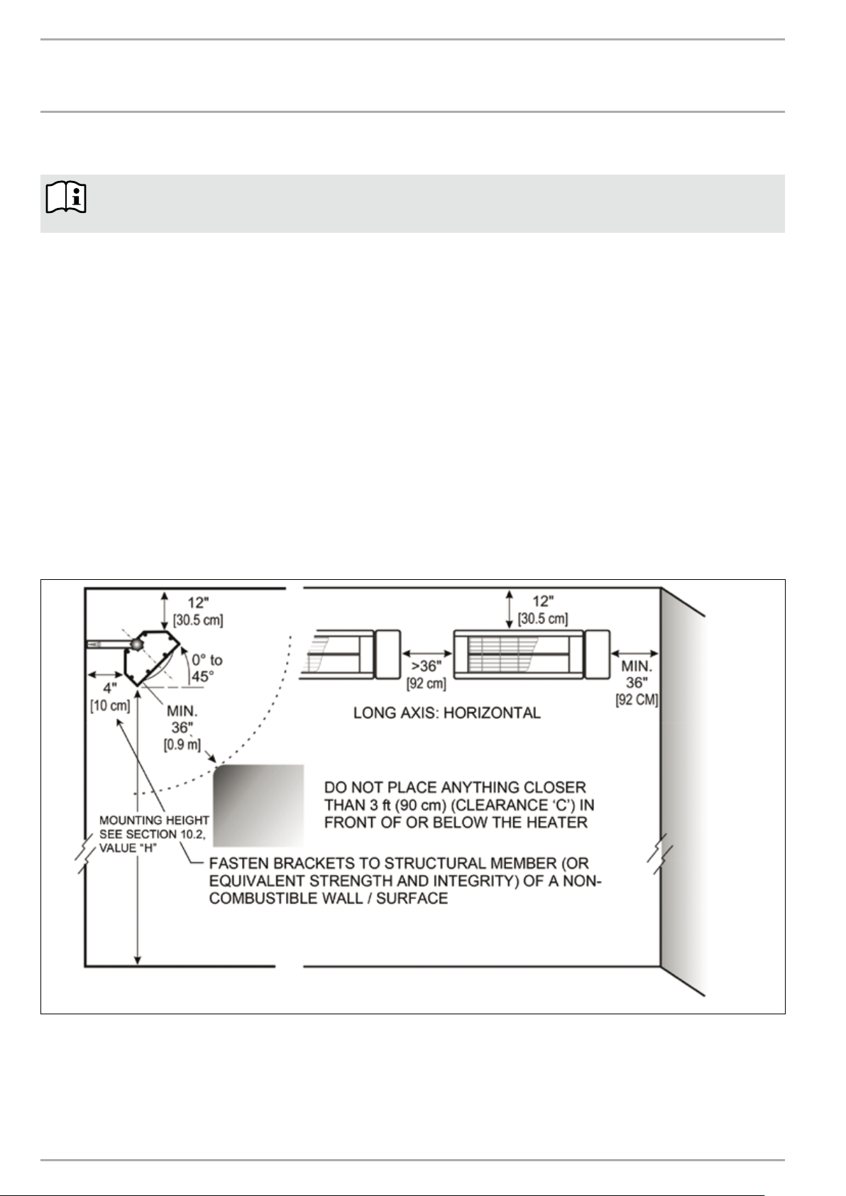
9.5 Minimum required clearances to surfaces and combustibles
9.6 Mounting the heater
1. Mount the heater securely to a surface or structural member, and maintain at least all minimum clearances indicated in section 9.5.
2. Use the mounting bracket supplied with the heater - see drawings below, next page.
3. Hardware to fasten the mounting bracket to the structure is field supplied by the installer since the type of hardware fastening is
determined by site conditions.
8 |SUNWARMTH™ CIR INFRARED HEATER WWW.STIEBEL-ELTRON-USA.COM
Page 9

INSTALLATION
(72.5)
INSTALLATION
4. Models CIR 150-1 I and CIR 150-1 O: If at all possible, locate
the mounting bracket so that the electrical cord (8 ft [2.4 m]) can
be plugged into an electrical outlet (grounded 120 V) without
stretching the electrical cord taut. See important notice (section
9.3, pg. 7) regarding the use of an extension cord.
5. Never allow an electrical cord to pass in front of the heater or
to come into contact with any hot surface of the heater.
6. The mounting bracket fastens to the structure using field
supplied bolts or lag screws through two holes in one side of
the bracket. The heater bracket fastens to the mounting bracket
through the outermost hole on the other leg of the mounting
bracket using the bolt, lock washer and nut supplied.
7. Fasten the mounting bracket plumb and level so that the heater
is oriented horizontally on the long axis.
8. Ensure that the mounting bracket is firmly fastened to the
structure with bolts or lag screws (field supplied) of sufficient
strength and integrity to support the weight and prevent movement
of the heater. It is recommended to fasten the mounting bracket
to a structural member (wall stud, etc.).
Mounting Bracket for CIR 150-1 I and CIR 150-1 O
4 5/16˝
(110)
3 1/8˝
(80)
1/2˝
(13)
3-Ø13
Mounting Bracket for CIR 200-2 O
2 15/16˝
(75)
(42)
1 5/8˝
1 5/8˝
(42)
6 5/8˝
(168)
3 1/8˝
(80)
1/2˝
(13)
5 15/16˝
3-Ø13
(32)
1 1/4˝
(150)
ENGLISH
1 5/8˝
1 3/16˝
1 1/2˝
(42)
3/8˝
(10)
(29.5)
(38)
1 5/8˝
(42)
1 1/4˝
(32)
(203)
Ø8.5
M8
(10)
1 1/4˝
(32)
Ø8.5
1 3/16˝
1 1/2˝
3/8˝
(29.5)
(38)
2 7/8˝
(32)
1 1/4˝
(170)
6 11/16˝
8˝
2 1/2˝
(63)
M8
3 5/8˝
(92.5)
WWW.STIEBEL-ELTRON-USA.COM SUNWARMTH™ CIR INFRARED HEATER| 9
Page 10

INSTALLATION
INSTALLATION
Mounting Bracket for CIR 400-2 O
13 3/16˝
(97)
1 9/16˝
7 1/2˝
(190)
(40)
1 9/16˝
(40)
1/2˝
(13)
1 1/4˝
7 1/2˝
(32)
8
(190)
1 1/4˝
(32)
M8
1/2˝
8
(13)
1 9/16˝
5 3/8˝
Ø8
(40)
(137)
9. Attach the heater bracket to the mounting bracket (outermost
hole), using the bolt, lock washer and nut supplied. Tighten
securely.
10. The bracket attached to the top of the heater allows rotation up
to 45° on the short axis by loosening the attachment bolt.
11. Once heater position is established, tighten all nuts and bolts at
mounting and heater bracket connections to maintain the heater
in a secure and stable position.
12. Read and follow all warnings, and the following section on
Operation to enjoy safe operation of the heater.
9.7 Power supply
DANGER Electrocution!
Carry out all electrical connection and installation
work in accordance with all national, state and local
building code.
DANGER Electrocution!
Each 240 V heater must be wired directly to a circuit
with a timer switch and the proper size breaker and
wire gauge.
DANGER Electrocution!
Do not plug models CIR 200-2 O or CIR 400-2 O into
a wall outlet.
9.7.1 CIR 150-1 I and CIR 150-1 O
Plug heater into a properly grounded wall outlet connected to a
120 V, 60Hz, 15 Amp copper wire circuit that is properly grounded
and controlled by a timer switch.
9.7.2 CIR 200-2 O
Using 12 AWG copper wire, connect the heater to a 240 V, 60Hz,
15 Amp circuit breaker that is properly grounded and controlled
by a timer switch.
9.7.3 CIR 400-2 O
Using 12 AWG copper wire, connect the heater with a timer switch
to each of two independent 240 V, 60Hz, 15 Amp circuit breakers
that are each properly grounded.
The specified voltage on the nameplate must match
the voltage at the circuit breaker panel.
Electrical connection must be performed by a qualified electrical
tradesperson. Installation must conform with the latest edition
Electrical Code ANSI/NFPA N0 70 in the U.S.A. and PART 1 CSA
C22.1 in Canada.
10 |SUNWARMTH™ CIR INFRARED HEATER WWW.STIEBEL-ELTRON-USA.COM
Page 11
INSTALLATION
CIR 200-2 O Wiring
INSTALLATION
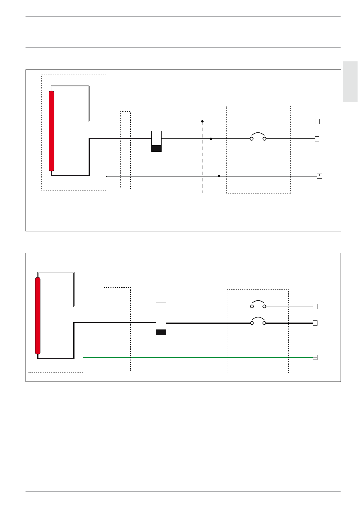
9.7.4 Wiring diagram - CIR 150-1 I, CIR 150-1 O
Lamp
Outllet
K1
Off Delay Timer
SPST
CB1
Single Pole Circuit Breaker
Minimum 15 A
ENGLISH
N
120 VAC, 60 Hz
L
CIR 150-1 I/O
120 VAC, 60 Hz, 13 A
To Other Outlets
Properly grounded copper wire circuit only
CIR 150-I is for indoor use only
If CIR 150-1 O is used outdoors an approved outdoor outlet must be used.
9.7.5 Wiring diagram - CIR 200-2 O
White
Lamp
Black
Junction
Box
Green
K1
Off Delay Timer
DPST
in Circuit
Breaker Panel
CB1
Dual Pole Circuit Breaker
15 A
L2
240 VAC, 60 Hz, 9 A
L1
CIR 200-2 O
Breaker Panel
WWW.STIEBEL-ELTRON-USA.COM SUNWARMTH™ CIR INFRARED HEATER| 11
Page 12

INSTALLATION
CIR 400-2 O Wiring
!
!
INSTALLATION
9.7.6 Wiring diagram - CIR 400-2 O
Lamp 2Lamp 1
CIR 400-2 O
9.8 Heat lamp replacement
WARNING
Heater service should only be performed by a qualified
electrician. Failure to comply could result in personal
injury, death, fire and/or property damage. Tampering
with the heater by an unqualified person will void the
warranty.
WARNING
Before servicing, make sure the power has been turned
off at the circuit breaker panel or unplugged from the
wall outlet, and that the heating element of the heater
is cool. Ensure the power remains disconnected the
entire time the unit is being serviced. Failure to do so
could result in serious burns, electrocution, serious
bodily injury, or death.
White
Black
Junction
Box
Green
Brown
Blue
K1
Off Delay Timer
4PST
L2
240 VAC, 60 Hz, 9 A
CB1
Dual Pole Circuit Breaker
15 A
CB2
Dual Pole Circuit Breaker
15 A
L1
L2
240 VAC, 60 Hz, 9 A
L1
Breaker Panel
The heater requires some disassembly to access electrical
connections when replacing the lamp.
Use a container to securely store disassembled components and
screws.
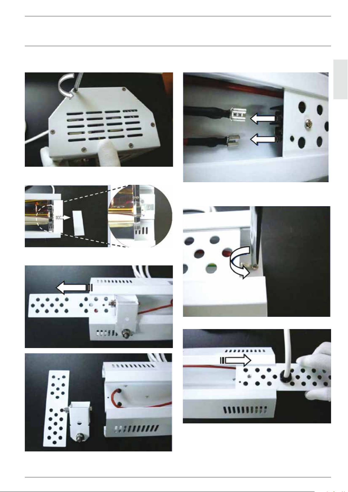
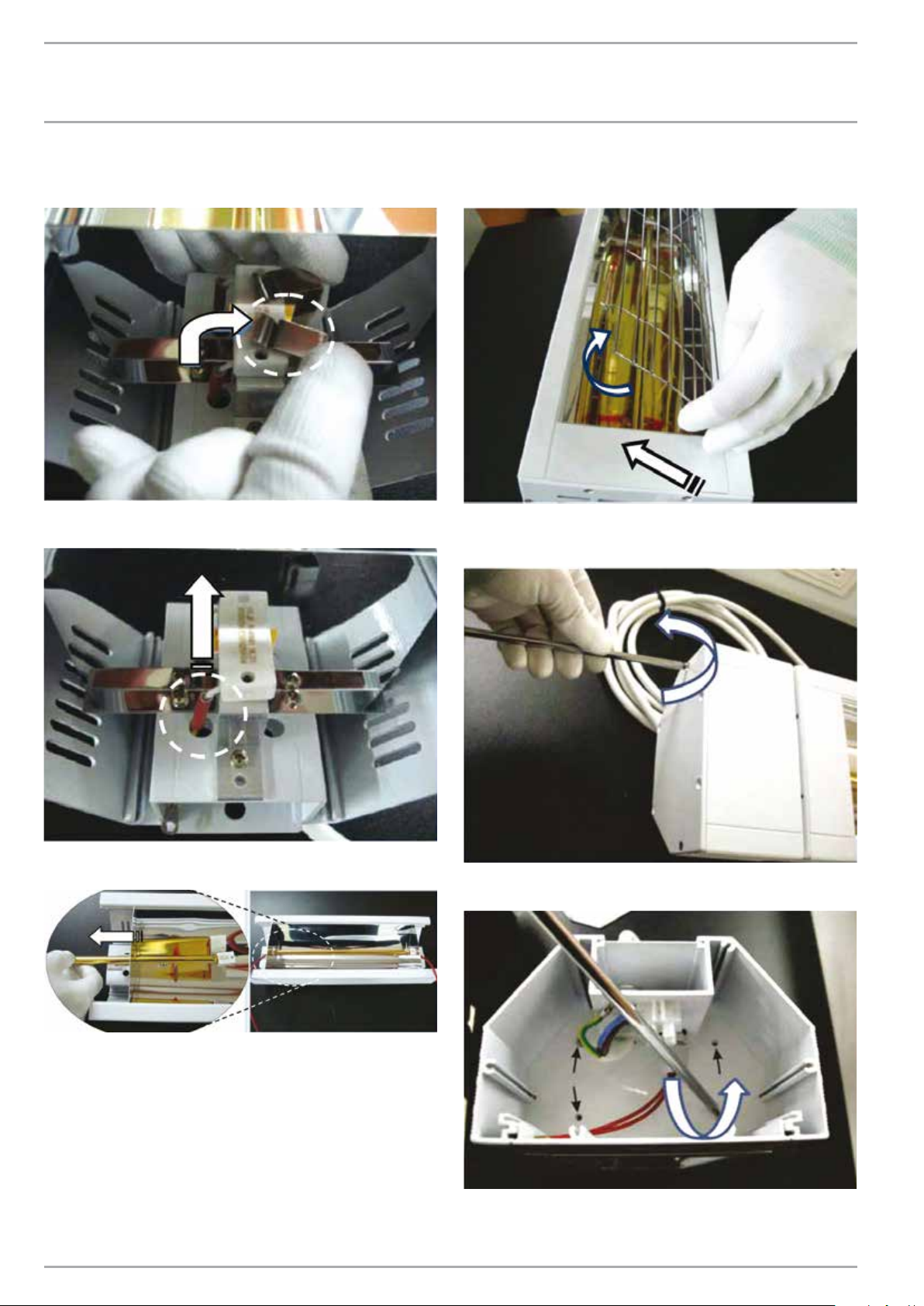
9.8.1 Heat lamp replacement - CIR 150-1 I
1. Compress the width of the protective grill to retract the
wire tabs from under one edge of the heater body.
» Rotate the loose edge of the grill up and away from heater
body.
» Pull the grill away from heater and remove from other edge
of heater body - place safety grill in a secure storage area:
CAUTION
Always wear cotton or other fabric gloves when
replacing heat lamp.
Do not touch the lamp surface with your bare hands.
Oils from your skin will cause damage to the lamp.
12 |SUNWARMTH™ CIR INFRARED HEATER WWW.STIEBEL-ELTRON-USA.COM
Page 13
INSTALLATION
INSTALLATION
2. Remove end cover at both ends of heater. Six (6) Phillips screws
hold the end cover in place. Remove the screws to secure storage:
3. Slide out the face plate at each end of heater to expose both
ends of the heat lamp:
5. Disconnect electrical supply cord spade connectors from
terminals:
ENGLISH
6. Disconnect ground wire (electrical supply cord) from the heater
body by removing the anchor screw from the eye of the ground
terminal:
4. Turn heater face down, and slide the center cover plate and
the heater mounting bracket out of the heater:
7. Slide power cord retainer plate from heater body:
WWW.STIEBEL-ELTRON-USA.COM SUNWARMTH™ CIR INFRARED HEATER| 13
Page 14
INSTALLATION
INSTALLATION
8. Turn heater face up. Each end of the lamp has a rectangular
retainer block. Remove the stainless steel clips that secure the
retainer blocks at each end of the lamp:
9. Pull the lamp wires up and out from the heater body at each
end of the lamp:
» Pull the grill away from heater to remove from other edge
of heater body - place safety grill in a secure storage
container:
2. Remove connection box end cover. Six (6) Phillips screws hold
the end cover in place. Remove the screws and keep in a secure
storage area:
10. Slide the lamp out through the reflector end plate. Properly
and safely dispose of lamp:
11. The heat lamp is fragile - handle with care! Wear gloves. Do
not touch lamp with bare fingers! Oils from your skin will damage
the lamp.
» Install the new replacement lamp
» Reassemble heater in reverse order of steps above.
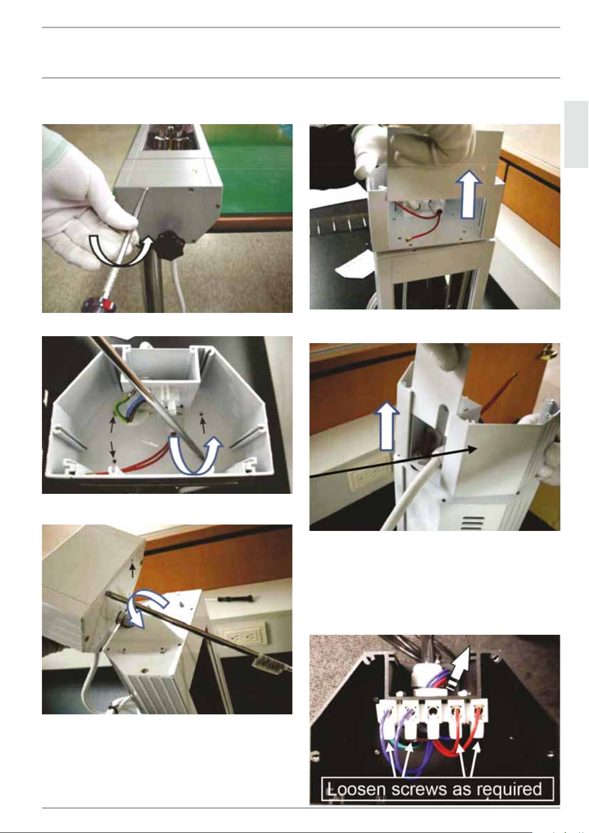
9.8.2 Heat lamp replacement - CIR 150-1 O and CIR 200-2 O
1. Compress the width of the protective grill to retract the wire
tabs from under one edge of the heater body.
» Rotate the lose edge of the grill up and away from
heater body.
14 |SUNWARMTH™ CIR INFRARED HEATER WWW.STIEBEL-ELTRON-USA.COM
3. Remove connection box end cover. Six (6) Phillips screws hold
the end cover in place. Remove the screws to secure storage:
Page 15

INSTALLATION
INSTALLATION
4. Remove 2 Phillips screws that fasten the connection box face
plate in place:
5. Disconnect electrical supply cord spade connectors from
terminals:
7. Slide power cord retainer plate from heater body (top surface
of heater):
ENGLISH
Connection
box
8. Loosen plastic collar on second Liquid Tight Connector that
secures red wires through connection box end plate.
» Slide red wires out of connection box.
» Set connection box aside:
6. Loosen 2 screws in terminal block that connect the red heat
lamp wires in place. Remove ends of red wires from terminal
block.
6A. Loosen plastic collar on Liquid Tight Connector that secures
red wires to connection box:
Connection
box
Heater
body
9. Remove end plate from heater: 6 Phillips screws fasten the
heater body end plate in place:
WWW.STIEBEL-ELTRON-USA.COM SUNWARMTH™ CIR INFRARED HEATER| 15
Page 16

INSTALLATION
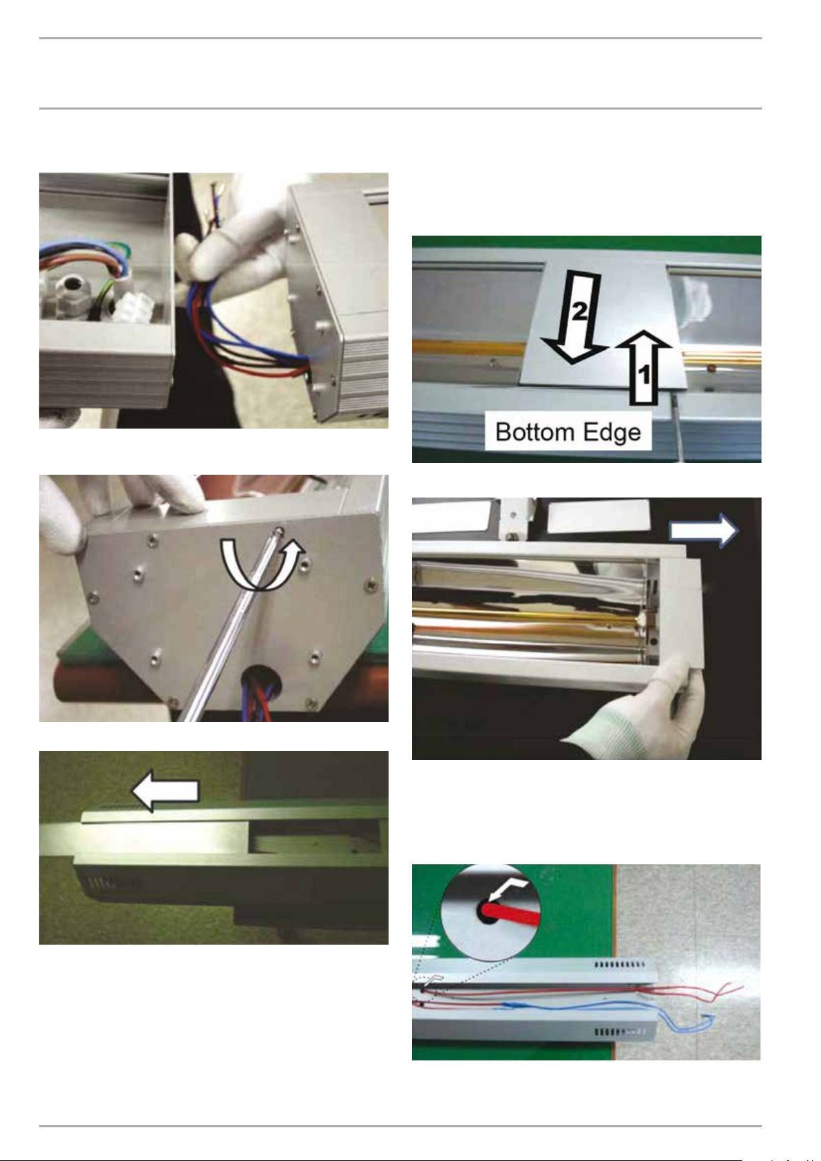
INSTALLATION
10. Slide cover plates and heater mounting bracket out from top
side of heater. Remove remaining end plate from other end of
heater:
11. Slide face plate out from each end of heater:
13. The heat lamp is fragile! Carefully side old heat lamp out of
heater through rectangular slot in end of reflector:
» Carefully install new heat lamp and clip in place.
» Reverse steps above to reassemble the heater.
9.8.3 Heat lamp replacement - CIR 400-2 O
1. Compress the width of the protective grill to retract the wire
tabs from under one edge of the heater body.
» Rotate the loose edge of the grill up and away from heater body.
» Pull the grill away from heater to remove from other edge of
heater body - place safety grill in a secure storage container.
» Repeat grill removal for other lamp if required:
12. Remove the heat lamp retainer clip at each end of lamp:
16 |SUNWARMTH™ CIR INFRARED HEATER WWW.STIEBEL-ELTRON-USA.COM
Page 17
INSTALLATION
INSTALLATION
2. Remove end plate from heater: 6 Phillips screws fasten the
heater body end plate in place:
3. Remove 4 Phillips screws that hold connection box to heater:
5. Slide the connection box front face plate out from the electrical
connection box:
ENGLISH
6. Slide power cord retainer plate from electrical connection box
(top surface):
4. Remove the 2 Phillips screws that fasten the electrical
connection box front face plate in place:
Electrical
connection
box
7. Loosen screws in terminal block to remove wires as required:
» RED wires connect to Lamp #1 (closer to connection box)
» BLUE wires connect to Lamp #2 (further end from box)
» Do not disconnect power supply wires
» Loosen the threaded clamping collar on the Liquid Tight
Connector located behind the wiring terminal
» Pull wires out through the Liquid Tight Connector and top of
electrical connection box:
WWW.STIEBEL-ELTRON-USA.COM SUNWARMTH™ CIR INFRARED HEATER| 17
Page 18
INSTALLATION
INSTALLATION
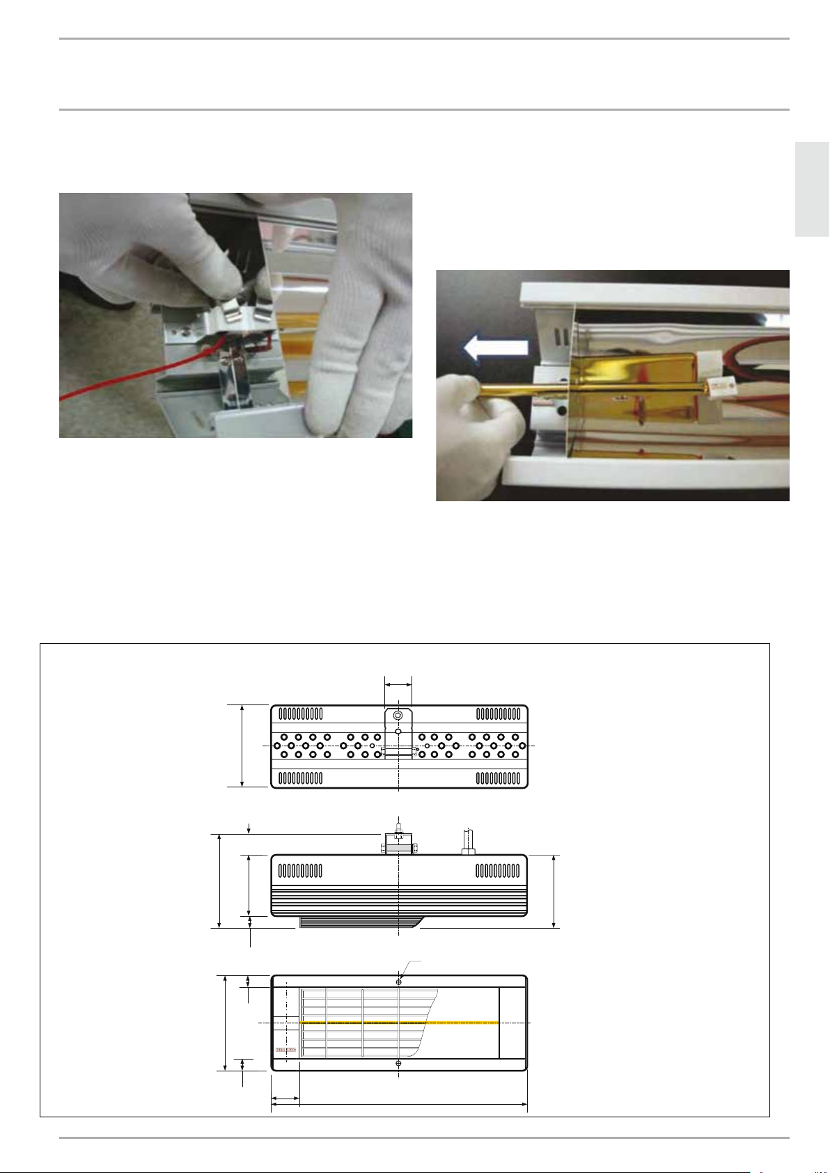
8. Slide lamp wires out of electrical connection box. Set electrical
connection box aside:
9. Remove interior end plate from heater: 6 Phillips screws fasten
the heater body end plate in place:
11. Remove the center face plate:
» The BOTTOM edge of the center Face Plate does not have a
lower lip
» Insert a fine edged slot screw driver between the heater body
and the BOTTOM edge of the face plate
» Pry the face plate from the heater body, and remove to storage:
12. Slide the end face plates out from each end of the heater:
10. Slide top cover plates out each end of top side of heater:
13. NOTE: For this step, keep the heat lamp retainer clips in place
at each end of lamps. Heat lamp is fragile - use caution when
feeding wires through holes.
» Carefully feed each lamp wire from the top of the heater through
the hole in the heater body so that the wire is inside the heater
body (same as the lamp):
18 |SUNWARMTH™ CIR INFRARED HEATER WWW.STIEBEL-ELTRON-USA.COM
Page 19
INSTALLATION
3-Ø13
1 9/16˝
4 5/16˝
(110)
6 11/16˝
(170)
3 1/8˝
(80)
1/2˝
(13)
1 1/4˝
(32)
5 11/16˝
APPLIANCE HANDOVER
14. Remove the heat lamp retainer clips both ends of lamps.
» One clip at each end of heater
» Two clips in the center of heater:
15. The heat lamp is very fragile - handle and assemble with great
care!
» Carefully slide old heat lamp out of heater through rectangular
slot in end of reflector.
» CAREFULLY install new heat lamp and clip in place.
» Reverse steps above to reassemble the heater.
» Take particular care not to damage the lamp at Step 14 and
Step 13:
10. Appliance handover
Explain the functions of the appliance to the user. Draw special attention to the safety information. Hand the operating and installation
instructions to the user.
ENGLISH
11. Specification
11.1 Dimensions - CIR 150-1 I
(40)
(145)
5 11/16˝
1 5/16˝
(33)
(95)
3 3/4˝
(17)
11/16˝
5/8˝
(16)
#10
Rear
Top
(112)
4 7/16˝
(145)
inches
(mm)
1 9/16˝
5/8˝
(16)
(40)
15 9/16˝
(395)
Front
WWW.STIEBEL-ELTRON-USA.COM SUNWARMTH™ CIR INFRARED HEATER| 19
Page 20
INSTALLATION
1 9/16˝
3-Ø13
4 5/16˝
(110)
6 11/16˝
(170)
3 1/8˝
(80)
1 5/8˝
(42)
1/2˝
(13)
1 1/4˝
(32)
1/2˝
(13)
1 9/16˝
(40)
1 9/16˝
(40)
13 3/16˝
(97)
SPECIFICATION
11.2 Dimensions - CIR 150-1 O & CIR 200-2 O
(40)
inches
(mm)
Rear
Top
Front
(145)
5 11/16˝
3˝
(76)
1 5/16˝
(33)
(95)
(145)
3 3/4˝
(108)
4 1/4˝
#10
15 9/16˝
(395)
18 9/16˝
(471)
1 9/16˝
(40)
5 11/16˝
(17)
11/16˝
5/8˝
(16)
(145)
5 11/16˝
5/8˝
(16)
11.3 Dimensions - CIR 400-2 O
Rear
Top
3 15/16˝
(100)
(112)
4 7/16˝
38 1/2˝
(895)
31 5/16˝
(795)
31 5/16˝
(795)
Front
inches
(mm)
20 |SUNWARMTH™ CIR INFRARED HEATER WWW.STIEBEL-ELTRON-USA.COM
1 9/16˝
(40)
3 1/8˝
(80)
1 9/16˝
(40)
5/8˝
5/8˝
(95)
3 3/4˝
11/16˝
(16)
(16)
5 11/16˝
(17)
(145)
5 11/16˝
(145)
Page 21

INSTALLATION
SPARE PARTS
11.4 Specification table
Model CIR 150-1 I CIR 150-1 O CIR 200-2 O CIR 400-2 O
Item No. 234 047 234048 234049 234050
Usage indoor only indoor/outdoor indoor/outdoor indoor/outdoor
Testing standard ANSI/UL 1278 ANSI/UL 1278 ANSI/UL 2021 ANSI/UL 2021
Voltage, 60Hz 115–120 V 115–120 V 230–240 V 230–240 V
Wattage 1.5 kW 1.5 kW 2.0 kW 4.0 kW
Amperage 12.5 A 12.5 A 8.3 A 2 x 8.3 A
Required number and size of
circuit breakers
Required wire size (copper) 14 AWG 14 AWG 12 AWG 12 AWG
Lamp temperature 2420 °F, ±360 °F
Lamp life (normal conditions) 5000 hours 5000 hours 5000 hours 5000 hours
Lamp color temperature 1600 K, ±200 K 1600 K, ±200 K 1600 K, ±200 K 1600 K, ±200 K
Height 5 11/16˝ / 145 mm 5 11/16˝ / 145 mm 5 11/16˝ / 145 mm 5 11/16˝ / 145 mm
Width 15 9/16˝ / 395 mm 18 9/16˝ / 471 mm 18 9/16˝ / 471 mm 38 ½˝ / 978 mm
Depth 4 7/16˝ / 112 mm 4 ¼˝ / 108 mm 4 ¼˝ / 108 mm 4 7/16˝ / 112 mm
Weight 4.85 lb / 2.2 kg 5.5 lb / 2.5 kg 5.5 lb / 2.5 kg 8.8 lb / 4.0 kg
IP-Rating IP20 IP24 IP24 IP24
Protection class I I I I
Color alpine white alpine white alpine white alpine white
N/A
1325 °C, ±200 °C
N/A
2420 °F, ±360 °F
1325 °C, ±200 °C
15 A
2420 °F, ±360 °F
1325 °C, ±200 °C
2 x 15 A
2420 °F, ±360 °F
1325 °C, ±200 °C
ENGLISH
12. Spare Parts
Model Protective Grill Heat Lamp
CIR 150-1 I BHSG LGHS1520 120V
CIR 150-1 O BHSG LGHS1524 120V
CIR 200-2 O BHSG LGHS2024 240V
CIR 400-2 O BHSG (2) LGHS2024 240V
13. What to do if ...
... the appliance does not heat up:
» For 120 V models, ensure that the unit is plugged into a properly
grounded 120 V wall outlet and that the timer switch is on.
» For 240 V models, ensure that the timer switch is on and that
there is adequate power available at the circuit breaker and that
the breaker hasn’t tripped. Check for faulty breaker(s).
... you notice a smell:
» For a short time after initial installation or after a long period
of inactivity, the unit may produce a smell. This is normal and
will not last long once regular operation resumes.
If you cannot remedy the fault, contact your contractor. To facilitate
and speed up your enquiry, please provide the number on the type
plate (Nr. XXXXXX - XXXX - XXXXXX)
WWW.STIEBEL-ELTRON-USA.COM SUNWARMTH™ CIR INFRARED HEATER| 21
Page 22

WARRANTY AND CUSTOMER SERVICE - ENVIRONMENT AND RECYCLING
!
The installation, electrical connect ion and fir st op er-
ation of th is appliance should be carried out by a
qualified installer.
!
The company does not accept liability for failure of any
goods supplied which have not been inst alled and
operated in accordance with the manufacturer‘s instructions.
Environment and recycling
sposing of the
r waste
!
!
WARRANTY
Residential & Commercial Warranty: Stiebel Eltron, Inc. warrants to the original consumer that the CIR Infrared Heater is free from
defects in material and/or workmanship under normal use and service for a period of one (1) year (12 months) from the date of
purchase, and subject to the conditions and limitations stated herein. Warning: Use of this heater in coastal salt-air regions can
result in corrosion of the aluminum body and reflector, and premature failure of the heat lamp. Corrosion and failure resulting
from use in coastal areas is not covered by warranty.
ONE YEAR (12 MONTH) WARRANTY
Subject to the conditions and limitations stated herein and defined below, during the term of this limited warranty, we will sup
ply any component part of the heater, excluding any labor , which the Manufacturer’s examination determines to be defective in
workmanship or material for a period of one year (12 months) from the date of purchase. This warranty applies to the heater’s
original owner, and only if the unit is installed and operated in accordance with the printed instructions accompanying the unit
and in compliance with all applicable installation, building codes and good trade practices. Failure to maintain the equipment
through regular maintenance or service by a qualified service technician shall void the warranty.
WHAT IS NOT COVERED
The Manufacturer shall not be responsible for any expenses, including service, labor, diagnosis, analysis,material or transportation/
shipping charges incurred during removal, repair, or reinstallation of this product, or any of its components or parts. All labor,
shipping, and/or service charges shall be paid by the owner. This warranty does not cover products that have been modified after
leaving the factory, improperly installed, misused, exposed to abuse or damaged by acts of God, negligence, accident, corrosive
or contaminated atmosphere, submersion in water, excessive thermal shock, impact, abrasion, normal wear due to use, alteration
or operation contrary to the owner’s manual or if the serial number has been altered, defaced or removed. This warranty shall
not apply if the voltage to the heater exceeds the rated voltage on the rating plate by more than 10%. The Manufacturer shall not
be liable for consequential damages arising out of, or in connection with, the use or performance of the product, or other indirect
damages with respect to loss of property, revenues, or profit, or costs of removal, installation or reinstallation, or for any default
or delay in performance by its warranty caused by any contingency beyond its control, including war, government restrictions, or
restraints, strikes, fire, flood, acts of God, or short or reduced supply of raw materials or products.
-
WARRANTY PROCEDURE
To establish the date of purchase for any purpose under this Limited Warranty, you must retain the original receipt that can establish
the purchase date of your unit. If you do not provide such documents, the start date of the term of this Limited Warranty will be
based upon the date of unit manufacture, plus thirty (30) days. Should the owner wish to return the CIR infrared heater for repair,
the owner must first secure written authorization from Stiebel Eltron, Inc. The owner shall be required to show proof of purchase
date, and to pay all transportation costs to return the defective part(s) or heater for repair or replacement. Warranty is void if heater
has been installed or used improperly or if design has been altered in any way.
LIMITATIONS AND EXCLUSIONS
This document contains all warranties made by the Manufacturer and may not be varied, altered or extended by any person.
There are no promises, or agreements extending from the Manufacture other than the statements contained herein. THIS
WARRANTY IS IN LIEU OF ALL WARRANTIES EXPRESSED OR IMPLIED, TO THE EXTENT AUTHORIZED BY THE LAWS OF THE JURISDICTION, INCLUDING SPECIFICALLY THE WARRANTIES OR MERCHANTIBILITY OF FITNESS FOR A PARTICULAR PURPOSE. All
warranties are limited in duration to 12 months. It is understood and agreed that the Manufacturer’s obligation hereunder
is limited to repairing or replacing parts determined to be defective as stated above. In no event shall the Manufacturer be
responsible for any alleged personal injuries or other special, incidental or consequential damages. As to property damages, contract, tort or other claim the Manufacturer’s responsibility shall not exceed the purchase priced paid for the product.
All replacement parts will be warranted for the unused portion of the warranty coverage period remaining on the applicable unit.
Some States and authorities do not allow certain warranty exclusions or limitations on how long a warranty lasts or the exclusions
or limitations of incidental or consequential damages. In such cases, the above limitations or exclusions may not apply to you and
are not intended to do so where prohibited by law. This warranty gives you specific legal rights. You may also have other rights
which vary by each jurisdiction.
22 |SUNWARMT™H CIR INFRARED HEATER WWW.STIEBEL-ELTRON-USA.COM
The installation, electrical connection and first
operation of this appliance should be carried out by a
qualified installer.
The company does not accept liability for failure of
any goods supplied which have not been installed
an operated in accordance with the manufacturer’s
instructions.
Please help us to protect the environment by di
packaging in accordance with the national regulations fo
processing.
Page 23

CONTIENDO | FUNCIONAMIENTO
INSTRUCCIONES IMPORTANTES
FUNCIONAMIENTO
1. INSTRUCCIONES IMPORTANTES ����������������������������� 23
1.1 Información sobre este documento ���������������������������� 24
1.2 Explicación de los símbolos ������������������������������������� 24
2. Seguridad ������������������������������������������������������ 25
2.1 Uso previsto �������������������������������������������������������� 25
2.2 Información sobre seguridad �����������������������������������25
2.3 Certificación ETL / UL / CSA ������������������������������������� 26
3. Registre su producto ����������������������������������������� 26
4. Descripción del aparato �������������������������������������� 26
5. Funcionamiento ����������������������������������������������� 26
5.1 Puesta en marcha ������������������������������������������������� 26
5.2 Desconexión del calefactor �������������������������������������� 26
6. Limpieza, cuidado y mantenimiento ������������������������ 26
6.1 Mantenimiento ����������������������������������������������������� 26
6.2 Limpieza ������������������������������������������������������������� 27
INSTALACIÓN
7. Seguridad ������������������������������������������������������ 27
7.1 Instrucciones generales de seguridad ������������������������27
7.2 Instrucciones, normas y reglamentos ������������������������� 27
8. Descripción del aparato �������������������������������������� 27
8.1 Entrega estándar �������������������������������������������������� 27
9. Instalación ����������������������������������������������������� 27
9.1 Consideraciones y directrices sobre el diseño del proyecto
������������������������������������������������������������������������ 27
9.2 Especificaciones recomendadas de montaje y cobertura � 29
9.3 Instrucciones generales de instalación ����������������������� 29
9.4 Ubicación del calefactor ������������������������������������������ 30
9.5 Distancias mínimas de separación exigidas respecto de
superficies y combustibles �������������������������������������� 30
9.6 Montaje del calefactor �������������������������������������������� 31
9.7 Suministro eléctrico ����������������������������������������������� 32
9.8 Sustitución de la lámpara de calor ���������������������������� 34
10. Entrega del aparato ������������������������������������������ 42
11. Especificaciones ���������������������������������������������� 42
11.1 Dimensiones - CIR 150-1 I ��������������������������������������� 42
11.2 Dimensiones - CIR 150-1 O & CIR 200-2 O ��������������������43
11.3 Dimensiones - CIR 400-2 O ��������������������������������������43
11.4 Tabla de especificaciones ���������������������������������������� 44
12. Piezas de repuesto ������������������������������������������� 44
13. Qué hacer si... ������������������������������������������������� 44
GARANTÍA Y SERVICIO DE ATENCIÓN AL CLIENTE
MEDIO AMBIENTE Y RECICLAJE
1. INSTRUCCIONES IMPORTANTES
GUARDE ESTAS INSTRUCCIONES
Al utilizar aparatos eléctricos, siempre deben tomarse unas
precauciones básicas para reducir el riesgo de incendio, descarga
eléctrica, daños materiales, lesiones y muerte. Estas son algunas
de esas precauciones:
1. La instalación de este calefactor debe realizarla únicamente un
electricista calificado. Lea y comprenda todas las instrucciones
antes de instalar, utilizar o hacerle el mantenimiento a este
calefactor. Si la instalación, manejo, ajuste, modificación, revisión
o mantenimiento se realizan de forma incorrecta, puede existir
un riesgo de incendio y descarga eléctrica. Así mismo, pueden
producirse daños materiales, lesiones o incluso la muerte.
2. Este calefactor se calienta cuando está en funcionamiento.
Para evitar quemaduras, no toque las superficies calientes con
la piel desnuda. Mantenga los cables eléctricos y los materiales
combustibles, como muebles, almohadas, ropa de cama, papeles,
ropa, cortinas, etc., a una distancia mínima de 3 pies (1 m) respecto
del frente, los laterales y la parte trasera del calefactor.
3. Es necesario extremar las precauciones cuando cualquier
calefactor lo utilizan niños o personas inválidas, o cuando se usa
cerca de ellos.
4. Nunca deje el calefactor desatendido mientras esté en
funcionamiento. Desenchufe los modelos de 120 V o desconecte
el (los) cortacircuitos de los modelos de 240 V cuando el aparato
no esté en funcionamiento.
5. No ponga en marcha ningún calefactor si tiene el cable o el
enchufe dañado, si ha mostrado un mal funcionamiento, si ha
sufrido una caída o si ha resultado dañado en modo alguno.
Regrese el calefactor a un servicio técnico autorizado para su
revisión, ajuste eléctrico o mecánico, o reparación.
6. Estos calefactores no están destinados para su uso en cuartos
de baño, cuartos de lavandería y ubicaciones de interior similares.
Nunca coloque un calefactor en un lugar de donde pueda caer a
una bañera o a otro recipiente con agua.
7. EL MODELO “CIR 150-1 I” ESTÁ DESTINADO EXCLUSIVAMENTE
PARA USO EN INTERIORES. No utilice este modelo en exteriores o
en ambientes húmedos. Los modelos CIR 150-1 O, CIR 200-2 O y CIR
400-2 O pueden utilizarse en exteriores o en ambientes húmedos.
8. No pase el cable por debajo de alfombras. No tape el cable
con alfombrillas, tapetes o similares. Coloque el cable fuera de las
zonas de tránsito, donde no vaya a provocar tropiezos.
9. Recoja el cable en el lateral y en la parte posterior del calefactor;
evite que el cable repose sobre el calefactor.
10. Para desconectar el calefactor, retire el enchufe de la toma de
corriente (modelos de 120 V) o apague el interruptor de la fuente
de alimentación (modelos de 240 V).
11. Los modelos de 120 V, CIR 150-1 I y CIR 150-1 O, deben
enchufarse a una toma de corriente de 120 V correctamente
conectada a tierra y controlada mediante un temporizador.
12. Los modelos de 240 V deben estar integrados de manera
fija en un circuito correctamente conectado a tierra y controlado
mediante un temporizador. Es necesario usar cable de cobre.
13. No introduzca ni deje entrar ningún objeto extraño en el
calefactor ni en ninguna abertura de ventilación o escape, ya que
ello puede dar lugar a una descarga eléctrica, incendio o daño
en el calefactor. Así mismo, puede producir daños materiales,
lesiones personales o incluso la muerte.
ESPAÑOL
WWW.STIEBEL-ELTRON-USA.COM SUNWARMTH™ CIR INFRARED HEATER| 23
Page 24

FUNCIONAMIENTO
INSTRUCCIONES IMPORTANTES
14. Para evitar un posible incendio, no bloquee las entradas de
aire ni el escape en modo alguno. No utilice el calefactor sobre una
superficie blanda, como una cama, ya que las aberturas podrían
quedar bloqueadas.
15. Utilice este calefactor únicamente tal y como se describe en
este manual. Cualquier otro uso no recomendado por el fabricante
puede provocar un incendio, descarga eléctrica, daños materiales,
lesiones personales o incluso la muerte.
16. Con los modelos de 120 V, evite usar un alargador ya que este
puede sobrecalentarse y provocar un incendio. IMPORTANTE: Sin
embargo, si es necesario usar un alargador, este debe ser de un
calibre no inferior a 14 AWG y apto para un mínimo de 1875 vatios.
17. No toque el calefactor cuando esté en funcionamiento, ni
tampoco las piezas con corriente, por el riesgo de quemaduras,
descarga eléctrica, lesiones personales e incluso la muerte.
18. Todos los modelos de calefactores infrarrojos deben instalarse
conectados a un temporizador. Consulte con un electricista o
instalador local para obtener más detalles sobre la instalación.
19. No ajuste el calefactor sobre el soporte orientable mientras el
aparato esté en funcionamiento. Deje que el calefactor se enfríe
por completo antes de realizar ningún ajuste a la posición del
calefactor.
20. No mire fijamente a la lámpara del calefactor, ya que podría
sufrir lesiones en los ojos.
21. Después de su uso, deje enfriar por completo el calefactor
antes de tocarlo, moverlo o guardarlo.
22. Guarde estas instrucciones junto con el calefactor para
tenerlas siempre a mano como referencia. Conserve este manual
en un lugar seguro cerca del calefactor.
1.1 Información sobre este documento
El capítulo Funcionamiento está dirigido a usuarios e instaladores
calificados.
El capítulo Instalación está dirigido a instaladores calificados.
1.2.2 Palabras claves
PALABRA CLAVE Descripción
PELIGRO
ADVERTENCIA La palabra clave ADVERTENCIA indica información que
PRECAUCIÓN
1.2.3 Símbolos de texto y su disposición en esta
documentación
La palabra clave PELIGRO indica información que debe
respetarse, ya que de lo contrario pueden producirse
lesiones serias o incluso la muerte.
debe respetarse, ya que de lo contrario pueden producirse
lesiones serias o incluso la muerte.
La palabra clave PRECAUCIÓN indica información que
debe respetarse, ya que de lo contrario pueden producirse
lesiones relativamente serias o leves.
Lea atentamente el texto situado junto al símbolo “»”.
» El símbolo “»” indica que usted debe hacer algo. La acción que
usted debe realizar se describe paso a paso.
—Las secciones con el símbolo “–” muestran listas de ítems.
1.2.4 Información sobre el aparato
Nunca tape el aparato
1.2.5 Unidades de medida
En este documento, las dimensiones se indican en
pulg / mm. Cualquier unidad de medida alternativa
se especifica según corresponda.
Lea estas instrucciones atentamente antes de utilizar
el aparato y guárdelas como referencia para el futuro.
Pase las instrucciones a cualquier nuevo usuario.
1.2 Explicación de los símbolos
1.2.1 Formato de la información sobre seguridad
La información sobre seguridad comprende un símbolo de
advertencia y un texto con información. La información sobre
seguridad está impresa sobre un fondo de color gris.
Ejemplo:
1 2 3
PELIGRO Electrocución
Instale el aparato de manera que el dispositivo
de control...
4
1 Símbolo
2 Palabras claves (ver capítulo 1.2.2)
3 Descripción
4 Texto informativo
24 |SUNWARMTH™ CIR INFRARED HEATER WWW.STIEBEL-ELTRON-USA.COM
Page 25

FUNCIONAMIENTO
SEGURIDAD
2. Seguridad
Altura de montage
ver 9.2, Valore “H”
Fije los soportes al elemento estructural (o con una solidez e integridad
equivalentes) de una pared o superficie no combustible.
ESPAÑOL
Eje longitudinal: horizontal
No coloque ningún objeto a una distancia inferior a
3 pies (90 cm) (distancia de separación ‘C’) delante
o debajo del calefactor.
Distancias mínimas de separación exigidas respecto de superficies y combustibles
2.1 Uso previsto
Este aparato está diseñado para calentar zonas de vivienda. El
modelo CIR 150-1 I está destinado exclusivamente para uso en
interiores. Los modelos CIR 150-2 O, CIR 200-2 O y CIR 400-2 O
están destinados para uso en interiores o exteriores.
Cualquier otro uso distinto del descrito se considerará inadecuado.
El uso correcto de este aparato también implica seguir todas
las instrucciones de este manual. Cualquier modificación o
transformación del aparato anulará todos los derechos de garantía.
2.2 Información sobre seguridad
Ponga el aparato en marcha únicamente cuando esté
completamente instalado por un electricista autorizado y con todo
el equipamiento de seguridad conectado.
ADVERTENCIA Incendio
Nunca utilice este aparato...
— en estancias donde exista un riesgo de incendio
o explosión debido a la presencia de sustancias
químicas, polvo, gases o vapores.
— en las proximidades de tuberías o recipientes que
transporten o contengan materiales inflamables o
explosivos.
— si en la estancia se llevan a cabo tareas como
tendido de cables, pulido o sellado.
— si se utilizan aerosoles, abrillantadores para
suelos o productos similares que contengan
gasolina. Ventile la estancia suficientemente antes
de usar el calefactor.
ADVERTENCIA Incendio
Nunca utilice este aparato...
— si no se respetan las distancias mínimas de
separación respecto de la superficie de los objetos
adyacentes, como muebles, visillos, cortinas,
textiles u otros materiales inflamables (consulte
las distancias mínimas de separación en el
diagrama en capítulo 2 “Seguridad”).
— si un componente del aparato está dañado, si el
aparato ha sufrido una caída o si ya tenía un fallo.
ADVERTENCIA Lesiones
En los casos en que se permita a niños o a personas
con capacidades físicas, sensoriales o mentales
limitadas manejar este aparato, asegúrese de que esto
suceda solo bajo supervisión o después de que una
persona responsable de su seguridad les haya dado
instrucciones adecuadas.
Los niños deben ser supervisados y deben recibir
instrucciones apropiadas para garantizar que nunca
jueguen con el aparato.
ADVERTENCIA Incendio
Nunca sitúe ningún objeto ni material inflamable,
combustible o aislante, como ropa, cobijas, revistas,
recipientes con abrillantador para suelos o productos
derivados del petróleo, aerosoles o similares sobre el
aparato ni en las proximidades del mismo.
WWW.STIEBEL-ELTRON-USA.COM SUNWARMTH™ CIR INFRARED HEATER| 25
Page 26

FUNCIONAMIENTO
REGISTRE SU PRODUCTO
ADVERTENCIA Incendio
Nunca deje el calefactor desatendido mientras esté
en funcionamiento. El calefactor debe ser instalado
conectado a un temporizador. Desenchufe los modelos
de 120 V o desconecte el (los) cortacircuitos de los
modelos de 240 V cuando el aparato no esté en
funcionamiento.
ADVERTENCIA Electrocución
Desconecte siempre el calefactor de la fuente
de alimentación antes de realizar las tareas de
mantenimiento. En caso contrario, puede sufrir
lesiones graves o incluso la muerte.
No utilice ni coloque el aparato en un lugar de donde
podría caer a una bañera o a otro recipiente con agua.
ADVERTENCIA Quemaduras
Las superficies de la cubierta del aparato se calientan
durante el funcionamiento. No toque el aparato
mientras esté en funcionamiento. Deje que se enfríe
por completo después de usarlo y antes de tocarlo.
PRECAUCIÓN Sobrecalentamiento
Nunca tape el aparato.
2.3 Certificación ETL / UL / CSA
La certificación ETL / UL significa que el aparato cumple todos los
requisitos básicos de acuerdo con ANSI/UL 1278 o 2021 y CAN/
CSA C22.2 Nº 46.
2.3.1 Etiqueta de características
Consulte la placa de características.
La placa de características está ubicada en la parte superior del
aparato, en el centro de la parte exterior.
3. Registre su producto
Debe registrar este producto en un plazo de 90 días
desde la compra a través de nuestra página web para
activar cualquier garantía estándar o para optar a la
ampliación de la garantía. Visite nuestra página web
www.stiebel-eltron-usa.com y haga clic en “Registre
su producto”.
Si tiene alguna pregunta en relación con el proceso de registro o con las opciones de garantía, por favor, póngase en
contacto directamente con Stiebel Eltron USA en el número de
teléfono (800)-582-8423.
4. Descripción del aparato
Este aparato es un calefactor radiante que utiliza luz infrarroja de
onda corta. Está diseñado para calentar objetos, no el aire de un
espacio. Está diseñado para ser instalado sobre una pared o poste.
Todos los modelos son adecuados como sistema de calefacción
puntual en zonas de vivienda en interiores, como garajes
o talleres, o para ganado. Nota: El modelo CIR 150-1 I está
destinado exclusivamente para uso en interiores. Los modelos
CIR 150-1 O, CIR 200-2 O y CIR 400-2 también son apropiados
como sistema de calefacción puntual en zonas de vivienda en
exteriores, como patios, balcones y terrazas.
La cubierta del calefactor radiante está fabricada en aluminio. La
rejilla de protección y los tornillos son de acero inoxidable.
5. Funcionamiento
ADVERTENCIA Incendio
Nunca deje el calefactor desatendido mientras esté
en funcionamiento. El calefactor debe ser instalado
conectado a un temporizador. Desenchufe los modelos
de 120 V o desconecte el (los) cortacircuitos de los
modelos de 240 V cuando el aparato no esté en
funcionamiento.
5.1 Puesta en marcha
» Para los modelos de 120 V, enchufe la unidad a una toma de
corriente conectada a tierra y a un temporizador. Ajuste en el
temporizador el tiempo de funcionamiento deseado.
» Para los modelos de 240 V, encienda el (los) cortacircuitos al (a
los) que esté conectada la unidad. Ajuste en el temporizador el
tiempo de funcionamiento deseado.
5.2 Desconexión del calefactor
» Para los modelos de 120 V, desconecte la unidad mediante el
temporizador y desenchufe el cable de la unidad de la toma de
corriente.
» Para los modelos de 240 V, desconecte la unidad mediante
el temporizador y apague el suministro eléctrico mediante el
interruptor del panel del cortacircuitos.
Antes de comenzar el proceso de registro, le sugerimos que
recopile la siguiente información que necesitará:
Tipo; ejemplo: CIR 150-1 I (tomado de la etiqueta situada en la
parte superior de la unidad, en el centro)
Número que se indica después de “Nr.”
Lugar de compra
Fecha de compra
Nombre y apellido
Dirección de email
Dirección postal
Número de teléfono
26 |SUNWARMTH™ CIR INFRARED HEATER WWW.STIEBEL-ELTRON-USA.COM
6. Limpieza, cuidado y mantenimiento
ADVERTENCIA
!
Antes de limpiar la unidad, asegúrese de que el
suministro eléctrico haya sido desconectado en el
panel del cortacircuitos o de que el aparato esté
desenchufado de la toma de corriente. Así mismo,
compruebe que el componente calefactor del aparato
esté frío. Asegúrese de que el suministro eléctrico
permanece desconectado durante toda la instalación.
En caso contrario, podría sufrir quemaduras graves,
electrocución, lesiones graves o incluso la muerte.
Page 27

INSTALACIÓN
!
SEGURIDAD
6.1 Mantenimiento
» Revise el calefactor y el cable antes de cada uso.
» Limpie cualquier acumulación de polvo o suciedad de las
superficies y, en especial, del reflector y de las aberturas para
el paso del aire del cuerpo del calefactor (consulte la sección
6.2, “Limpieza”, pág. 27).
» Revise que el cable y el enchufe no estén dañados ni pelados:
- No ponga en marcha el calefactor si el cable o el enchufe
están dañados.
- Pida a un electricista calificado que sustituya las piezas
dañadas.
» Es necesario reparar o sustituir cualquier pieza o componente
dañado antes de poner en marcha el aparato.
6.2 Limpieza
PRECAUCIÓN Incendio
Nunca pulverice espray de limpieza en el reflector ni
en las aberturas.
Asegúrese de que no puede entrar humedad en el
aparato.
- Antes de limpiar el calefactor, desconéctelo del suministro
eléctrico y déjelo enfriar.
- No toque la lámpara de calor con los dedos, ya que la grasa de
la piel dañará la lámpara.
- Para limpiar la superficie del calefactor, el reflector y las
aberturas para el paso del aire: Utilice únicamente un paño
seco o húmedo o bien un chorro de aire de baja presión (un
limpiador de polvo en lata para computadoras).
- No utilice agentes de limpieza abrasivos o cáusticos.
- Nunca sumerja el aparato en agua. ¡Peligro mortal!
- Si un calefactor es expuesto a agua más allá del uso previsto en
los modelos de exteriores, pida a un electricista calificado que
revise y repare el calefactor antes de usarlo.
- Como parte de un mantenimiento regular, también recomendamos
pedir que se comprueben los componentes de control. Los
componentes de control y seguridad deben ser revisados por un
contratista en un plazo no superior a 10 años desde la puesta en
servicio del aparato.
7. Seguridad
Solo contratistas calificados deben llevar a cabo la instalación,
puesta en servicio, mantenimiento y reparación del aparato.
7.1 Instrucciones generales de seguridad
Garantizamos un funcionamiento fiable y exento de problemas
únicamente si se utilizan accesorios originales y piezas de repuesto
previstas para este aparato.
PELIGRO Electrocución
Si instala el aparato en la pared, hágalo de manera
que una persona que esté en la bañera o en la ducha
no alcance a tocar el equipo de control.
PRECAUCIÓN
— Respete las distancias mínimas de separación
respecto de la superficie de los objetos adyacentes
(consulte las distancias mínimas de separación en
la sección 9.5, pág. 30).
— Nunca instale el aparato directamente bajo un
enchufe de pared.
— Asegúrese de que el cable de alimentación no
entre en contacto con ningún componente del
aparato.
7.2 Instrucciones, normas y reglamentos
Cumpla todos los reglamentos e instrucciones
nacionales y regionales que sean aplicables.
8. Descripción del aparato
8.1 Entrega estándar
—Unidad del calefactor
—Soporte de montaje para pared, que incluye tornillos de
fijación, arandelas de retención y tuercas
9. Instalación
9.1 Consideraciones y directrices sobre el diseño
del proyecto
NOTA: Todos los calefactores infrarrojos CIR deben
instalarse conectados a un temporizador.
NOTA: Consulte en la sección 9.5 las distancias mínimas
de separación necesarias.
El tamaño y el número de calefactores (cantidad de aporte de
calor) necesarios en un área para proporcionar confort depende
de los siguientes factores:
9.1.1 Generales:
—Cantidad de movimiento de aire en esa área: la sensación
térmica producida por el viento frío requiere un aporte
adicional de calor
—Coloque cortavientos en todos los lugares donde sea
posible
—El confort que se logra mediante la calefacción puntual es
más eficaz si las personas reciben el calor desde al menos
dos lados
—Altura de montaje disponible para los calefactores en el
lugar del proyecto
9.1.2 Aplicaciones en interiores:
—Calefacción del espacio de toda la estructura (Se requiere
un cálculo preciso de la pérdida de calor. Para solicitar
ayuda con esto, póngase en contacto con Stiebel Eltron en
el número de teléfono 800-582-8423 o en la dirección de
e-mail info@stiebel-eltron-usa.com), o bien
—Calefacción puntual de solo una parte de una zona fría en
interiores
— El nivel de actividad de las personas: sentadas en reposo,
actividad física intensa, etc.
ESPAÑOL
WWW.STIEBEL-ELTRON-USA.COM SUNWARMTH™ CIR INFRARED HEATER| 27
Page 28

INSTALACIÓN
INSTALACIÓN
9.1.3 Aplicaciones en exteriores:
NOTA: EL MODELO “CIR 150-1 I” ESTÁ DESTINADO
EXCLUSIVAMENTE PARA USO EN INTERIORES.
—Cualquier área calefactada en exteriores se considera
calefacción puntual.
— Los modelos “CIR 150-1 O”, “CIR 200-2 O” y “CIR 400-2 O”
están destinados para uso en interiores o exteriores.
» Aumento de temperatura deseado:
—¿En qué estaciones se necesita confort y cuál es la
temperatura exterior de cálculo?
—Entonces, ¿cuál es el aumento deseado para obtener la
temperatura de confort? (10°, 15°, 20°, 25°?)
» Calcule el aporte necesario para obtener el aumento de
temperatura deseado:
Aporte necesario por área por grados de aumento para obtener
la temperatura de confort
Calefacción en
exteriores (con viento
de hasta 10 mph)
Calefacción puntual
en interiores (área
protegida, poco
movimiento de aire)
Densidad calorí-
ca
por grado F
W/(ft2)/°F
2
0.75
Densidad calorí-
ca
por grado C
W/(m2)/°C
40
14
» Fórmula del aporte = longitud del lugar x anchura del lugar x
aumento de temperatura x densidad calorífica por grado
Ejemplo:
—Patio exterior: 30 pies de longitud por 10 pies de anchura
—Aumento de temperatura deseado: 20°F (promedio del área)
—30 x 10 x 20 x 2 = 12,000 vatios de aporte total necesario
Compare los valores de la altura de montaje disponible y las
dimensiones del área en el lugar del proyecto con las alturas
de montaje recomendadas, la longitud y la anchura del área de
cobertura y la distribución promedio típica del calor en la sección
9.2 (pág. 29).
Disposición:
—Espacie los calefactores de manera uniforme alrededor del
perímetro (y, en caso necesario, en el centro o por toda el
área) para proporcionar una densidad calorífica suficiente
para conseguir el aumento de temperatura deseado, o bien
aplique calefacción puntual únicamente en lugares específicos
del área.
—Aporte calor desde al menos dos lados siempre que sea
posible.
NOTA: La información de diseño que se presenta en
este documento pretende servir de guía. La precisión
en la determinación o el cálculo de todos los factores
arriba indicados afectarán al rendimiento y a la
satisfacción. En concreto, el movimiento del aire
afectará al confort.
28 |SUNWARMTH™ CIR INFRARED HEATER WWW.STIEBEL-ELTRON-USA.COM
Page 29

INSTALACIÓN
INSTALACIÓN
9.2 Especificaciones recomendadas de montaje y cobertura
H
Modelo Vaitos
CIR 150-1 I, CIR 150-1 O 1500 W Minimum: 7′ (2.1 m)
CIR 200-2 O 2000 W Minimum: 8′ (2.4 m)
CIR 400-2 O 4000 W Minimum: 10′ (3.0 m)
Altura
de montage
Maximum: 8′ (2.4 m)
Maximum: 9′ (2.7 m)
Maximum: 11′ 6″ (3.5 m)
Ángulo de montaje de 45º
Área cubierta
Dimensiones del área calefactada
A
Longitud
calefactada
8′ 10″ (2.7 m)
9′ 10″ (3.0 m)
9′ 10″ (3.0 m)
11′ 2″ (3.4 m)
11′ 10″ (3.6 m)
13′ 5″ (4.1 m)
B
Anchura
calefactada
cerca del
calefactor
8′ 6″ (2.6 m)
9′ 2″ (2.8 m)
9′ 2″ (2.8 m)
9′ 10″ (3.0 m)
11′ 2″ (3.4 m)
14′ 1″ (4.3 m)
Ángulo aproximado de dispersión
del calor respecto del calefactor
C
Anchura
calefactada
lejos del
calefactor
16′ 1″ (4.9 m)
18′ 1″ (5.5 m)
18′ 1″ (5.5 m)
20′ (6.1 m)
23′ (7.0 m)
27′ 7″ (8.4 m)
D
Tamaño
del área
calefactada
108 ft2 (10.1 m2)
133 ft2 (12.4 m2)
133 ft2 (12.4 m2)
165 ft2 (15.3 m2)
205 ft2 (19.0 m2)
275 ft2 (25.4 m2)
ESPAÑOL
E
Densidad calorífica
promedio
13.9 W / ft2 (148.5 W / m2)
11.3 W / ft2 (121.0 W / m2)
15.0 W / ft2 (161.3 W / m2)
12.1 W / ft2 (130.7 W / m2)
19.5 W / ft2 (210.5 W / m2)
14.5 W / ft2 (157.5 W / m2)
9.3 Instrucciones generales de instalación
Lea todas las instrucciones y planifique la instalación antes de proceder.
Este aparato cumple las normas ANSI/UL 1278 o 2021 y está certificado según CAN/CSA C22.2 Nº 46.
El modelo CIR 150-1 I está aprobado exclusivamente para uso en interiores. No utilice este calefactor en ambientes como cuartos de
baño y cuartos de lavandería. El calefactor se suministra con un cable de 8 pies (2.4 m) con un enchufe de tres clavijas que debe ser
conectado a una toma de corriente de 115-120 V correctamente conectada a tierra en un circuito de suministro eléctrico de alambre
de cobre controlado por un temporizador.
Los modelos CIR 150-2 O, CIR 200-2 O y CIR 400-2 O están aprobados para uso en interiores y exteriores. No utilice estos calefactores
en ambientes como cuartos de baño y cuartos de lavandería. Estos modelos deben ser conectados a un circuito de suministro eléctrico
de alambre de cobre de 240 V correctamente conectado a tierra y controlado por un temporizador. La instalación debe cumplir los
requisitos descritos en la última edición del Código Eléctrico ANSI/NFPA N0 70 en Estados Unidos y en la PARTE 1 de CSA C22.1 en Canadá.
Junto con el calefactor, se suministra un soporte de montaje adecuado para instalar el aparato en una pared o en un poste. El calefactor
debe estar colocado en este soporte durante el funcionamiento. Los herrajes para fijar el soporte de montaje a la estructura vienen
determinados por las condiciones del lugar donde se ubique el aparato, y el instalador los suministra sobre el terreno.
ADVERTENCIA Incendio
Cuando instale los modelos CIR 150-1 I o CIR 150-1 O, evite usar un alargador ya que este puede sobrecalentarse y provocar
un incendio. Sin embargo, si es necesario usar un alargador, este debe ser de un calibre no inferior a 14 AWG y apto para
un mínimo de 1875 vatios.
WWW.STIEBEL-ELTRON-USA.COM SUNWARMTH™ CIR INFRARED HEATER| 29
Page 30

INSTALACIÓN
INSTALACIÓN
ADVERTENCIA Incendio
Respete siempre las distancias mínimas de separación respecto del suelo, el techo, las paredes y los materiales combustibles.
Consulte la sección 9.5 en la pág. 30.
9.4 Ubicación del calefactor
ADVERTENCIA
El uso de este calefactor en regiones costeras con aire salino puede producir corrosión en el cuerpo de aluminio y en el
reflector, así como el fallo prematuro de la lámpara de calor. La corrosión y el fallo derivados del uso del calefactor en
zonas costeras no quedan cubiertos por la garantía.
1. El calefactor está diseñado para ser montado en una pared o en un poste, y debe ser instalado a una altura mínima sobre el
suelo. Consulte más detalles en la sección 9.2.
2. Asegúrese de que las distancias de separación alrededor del calefactor cumplen o superan las distancias mínimas de separación
exigidas en la sección 9.5 pág. 30: por arriba, respecto del suelo, respecto de una pared lateral y respecto de materiales
combustibles.
3a. Los modelos CIR 150-1 I y CIR 150-1 O deben ser enchufados a una toma de corriente de 120 V correctamente conectada a tierra
y controlada por un temporizador. Asegúrese de que la toma de corriente sea fácilmente accesible para poder desconectar el
calefactor siempre que sea necesario.
3b. Los modelos CIR 200-2 deben ser conectados a un circuito de alambre de cobre de 240 V correctamente conectado a tierra y
controlado por un temporizador.
3c. El modelo CIR 400-2 O debe ser conectado a dos (2) circuitos independientes de alambre de cobre de 240 V correctamente
conectados a tierra y controlados por un temporizador.
4. Nunca debe situarse ni montarse el calefactor directamente bajo una toma de corriente de pared.
5. Se debe mantener una distancia mínima de 3 pies (36 pulgadas) [90 cm] entre la rejilla frontal y cualquier objeto inflamable (por
ejemplo, cortinas), paredes y otras estructuras.
6. No deje que ningún cable eléctrico pase por delante del calefactor ni que toque ninguna superficie caliente.
7. Dado que el aparato irradia calor, ningún obstáculo ni objeto, como un mueble, debe interponerse entre el calefactor y la persona
que debe recibir el calor.
8. No utilice el calefactor sobre una superficie blanda, como una cama, ya que las aberturas para el paso del aire podrían quedar
bloqueadas.
9. Un calefactor tiene superficies calientes y piezas internas que potencialmente pueden producir arcos y chispas. No utilice el
aparato en lugares donde se usen o almacenen gasolina, pintura o vapores o líquidos inflamables.
9.5 Distancias mínimas de separación exigidas respecto de superficies y combustibles
Eje longitudinal: horizontal
No coloque ningún objeto a una distancia inferior a
Altura de montage
ver 9.2, Valore “H”
Fije los soportes al elemento estructural (o con una solidez e integridad
equivalentes) de una pared o superficie no combustible.
3 pies (90 cm) (distancia de separación ‘C’) delante
o debajo del calefactor.
30 |SUNWARMTH™ CIR INFRARED HEATER WWW.STIEBEL-ELTRON-USA.COM
Page 31

INSTALACIÓN
(72.5)
INSTALACIÓN
9.6 Montaje del calefactor
1. Monte el calefactor de forma segura sobre una superficie o elemento estructural, respetando todas las distancias mínimas de
separación indicadas en la sección 9.5.
2. Use el soporte de montaje suministrado junto con el calefactor (consulte los dibujos de la página siguiente).
3. Los herrajes para fijar el soporte de montaje a la estructura los suministra el instalador sobre el terreno, ya que el tipo de herrajes
viene determinado por las condiciones del lugar donde se ubique el aparato.
4. Modelos CIR 150-1 I y CIR 150-1 O: Dentro de lo posible, ubique el soporte de montaje de manera que el cable eléctrico (8 pies [2.4
m]) pueda ser enchufado a una toma de corriente (de 120 V y con conexión a tierra) sin quedar tenso. Por favor, consulte un importante
aviso sobre el uso de alargadores en la pág 29.
5. Nunca deje que un cable eléctrico pase por delante del calefactor ni que entre en contacto con ninguna superficie caliente del aparato.
6. El soporte de montaje se fija a la estructura mediante pernos o tirafondos suministrados sobre el terreno y que encajan en dos
orificios de un lado del soporte. El soporte del calefactor se fija al soporte de montaje a través del orificio exterior de la otra pata del
soporte de montaje mediante el perno, la arandela de retención y la tuerca suministrados.
7. Fije el soporte de montaje nivelado y a plomo de manera que el calefactor quede orientado de forma horizontal sobre el eje
longitudinal.
8. Asegúrese de que el soporte de montaje quede firmemente sujeto a la estructura mediante pernos o tirafondos (suministrados sobre
el terreno) de suficiente resistencia e integridad para soportar el peso del calefactor y evitar su movimiento. Se recomienda fijar el
soporte de montaje a un elemento estructural (pared de entramado, etc.).
Soporte de montaje para los modelos CIR 150-1 I y CIR 150-1 O
4 5/16˝
(110)
3 1/8˝
(80)
1/2˝
(13)
3-Ø13
Soporte de montaje para el modelo CIR 200-2 O
2 15/16˝
(75)
3 1/8˝
(80)
1/2˝
(13)
3-Ø13
ESPAÑOL
1 5/8˝
1 3/16˝
1 1/2˝
(42)
3/8˝
(29.5)
(38)
(10)
1 5/8˝
(42)
1 1/4˝
(32)
(203)
Ø8.5
(32)
1 1/4˝
(170)
6 11/16˝
(42)
1 5/8˝
1 5/8˝
(10)
(42)
1 1/4˝
(32)
6 5/8˝
(168)
Ø8.5
8˝
2 1/2˝
(63)
3/8˝
M8
1 3/16˝
(29.5)
1 1/2˝
(38)
5 15/16˝
1 1/4˝
(150)
M8
(32)
3 5/8˝
(92.5)
WWW.STIEBEL-ELTRON-USA.COM SUNWARMTH™ CIR INFRARED HEATER| 31
2 7/8˝
Page 32

INSTALACIÓN
INSTALACIÓN
Soporte de montaje para el modelo CIR 400-2 O
13 3/16˝
(97)
1 9/16˝
7 1/2˝
(190)
(40)
1 9/16˝
(40)
1/2˝
(13)
1 1/4˝
7 1/2˝
(32)
8
(190)
1 1/4˝
(32)
M8
1/2˝
8
(13)
1 9/16˝
5 3/8˝
Ø8
(40)
(137)
9. Fije el soporte del calefactor al soporte de montaje (a través
del orificio exterior) mediante el perno, la arandela de retención
y la tuerca suministrados. Apriete firmemente.
10. El soporte fijado a la parte superior del calefactor permite
una rotación de hasta 45º sobre el eje transversal al aflojar el
perno de fijación.
11. Una vez fijada la posición del calefactor, apriete todas las
tuercas y pernos en las conexiones de los soportes de montaje
y del calefactor para mantener el aparato en una posición firme
y estable.
12. Lea y respete todas las advertencias, así como la siguiente
sección sobre el funcionamiento, para disfrutar de un
funcionamiento seguro del calefactor.
9.7 Suministro eléctrico
PELIGRO Electrocución
Lleve a cabo todas las conexiones eléctricas y todos
los trabajos de instalación de acuerdo con todos los
códigos de construcción: nacional, estatal y local.
PELIGRO Electrocución
Los calefactores de 240 V deben conectarse
directamente a un circuito con un temporizador, un
cortacircuitos de tamaño adecuado y un calibre de
cable correcto.
La conexión eléctrica debe realizarla un electricista profesional
calificado. La instalación debe cumplir los requisitos descritos en
la última edición del Código Eléctrico ANSI/NFPA N0 70 en Estados
Unidos y en la PARTE 1 de CSA C22.1 en Canadá.
9.7.1 CIR 150-1 I y CIR 150-1 O
Enchufe el calefactor a una toma de corriente de pared
correctamente conectada a tierra y conectada también a un
circuito de alambre de cobre de 120 V, 60Hz y 15 Amp. El circuito
debe estar correctamente conectado a tierra y controlado por un
temporizador.
9.7.2 CIR 200-2 O
Usando alambre de cobre de 12 AWG, conecte el calefactor a un
cortacircuitos de 240 V, 60Hz y 15 Amp que esté correctamente
conectado a tierra y controlado por un temporizador.
9.7.3 CIR 400-2 O
Usando alambre de cobre de 12 AWG, conecte el calefactor con un
temporizador a cada uno de dos cortacircuitos independientes de
240 V, 60Hz y 15 Amp que estén correctamente conectados a tierra.
PELIGRO Electrocución
No enchufe los modelos CIR 200-2 O o CIR 400-2 O a
una toma de corriente de pared.
El voltaje especificado en la placa de características
debe coincidir con el voltaje indicado en el panel del
cortacircuitos.
32 |SUNWARMTH™ CIR INFRARED HEATER WWW.STIEBEL-ELTRON-USA.COM
Page 33

INSTALACIÓN
CIR 200-2 O Wiring
INSTALACIÓN
9.7.4 Diagrama del cableado - CIR 150-1 I, CIR 150-1 O
Lámpara
K1
Temporizador con retardo de
desconexión, temporizador
Enchufe
unipolar (SPST)
CB1
Cortacircuitos unipolar
Mínimo 15 A
ESPAÑOL
N
120 VAC, 60 Hz
L
CIR 150-1 I/O
120 VAC, 60 Hz, 13 A
A otras tomas de
corriente del circuito
Panel del cortacircuitos
Solo un circuito de alambre de cobre correctamente conectado a tierra
El modelo CIR 150-I está destinado exclusivamente para uso en interiores.
Si se utiliza el modelo CIR 150-1 O en exteriores, se debe usar una toma de corriente aprobada para exteriores.
9.7.5 Diagrama del cableado - CIR 200-2 O
Blanco
Negro
Lámpara
Caja de
conexiones
Verde
Temporizador con retardo de desconexión,
K1
temporizador bipolar (DPST)
CB1
Cortacircuitos bipolar
15 A
L2
240 VAC, 60 Hz, 9 A
L1
CIR 200-2 O
Panel del cortacircuitos
WWW.STIEBEL-ELTRON-USA.COM SUNWARMTH™ CIR INFRARED HEATER| 33
Page 34

INSTALACIÓN
CIR 400-2 O Wiring
!
!
INSTALACIÓN
9.7.6 Diagrama del cableado - CIR 400-2 O
Blanco
Lámpara 2Lámpara 1
Negro
Caja de
conexiones
Verde
Marrón
Azul
Temporizador con retardo de desconexión,
CIR 400-2 O
9.8 Sustitución de la lámpara de calor
K1
temporizador de 4 polos
CB1
Cortacircuitos bipolar
15 A
CB2
Cortacircuitos bipolar
15 A
Panel del cortacircuitos
L2
240 VAC, 60 Hz, 9 A
L1
L2
240 VAC, 60 Hz, 9 A
L1
ADVERTENCIA
Las tareas de mantenimiento del calefactor solo
debe realizarlas un electricista calificado. En caso
contrario, podrían producirse daños materiales,
incendios, lesiones personales o incluso la muerte. La
manipulación del calefactor por parte de una persona
no capacitada anulará la garantía.
ADVERTENCIA
Antes de revisar la unidad, asegúrese de que el
suministro eléctrico esté desconectado en el panel del
cortacircuitos o de que el aparato esté desenchufado
de la toma de corriente. Así mismo, compruebe
que el componente calefactor del aparato esté frío.
Asegúrese de que el suministro eléctrico permanezca
desconectado durante todo el tiempo que la unidad
esté siendo sometida a revisión. En caso contrario,
podría sufrir quemaduras graves, electrocución,
lesiones graves o incluso la muerte.
PRECAUCIÓN
Use siempre guantes de algodón o de otro tejido
cuando sustituya la lámpara de calor.
No toque la superficie de la lámpara con las manos
desnudas. La grasa de la piel dañará la lámpara.
Es necesario desmontar parcialmente el calefactor para acceder a
las conexiones eléctricas y poder así sustituir la lámpara.
Utilice un recipiente para guardar de forma segura los componentes
desmontados y los tornillos.
34 |SUNWARMTH™ CIR INFRARED HEATER WWW.STIEBEL-ELTRON-USA.COM
Page 35

INSTALACIÓN
INSTALACIÓN
9.8.1 Sustitución de la lámpara de calor - CIR 150-1 I
1. Comprima el ancho de la rejilla de protección para retraer las
pestañas de alambre situadas bajo un extremo del cuerpo del
calefactor.
» Gire el extremo suelto de la rejilla hacia arriba y hacia afuera
respecto del cuerpo del calefactor.
» Separe la rejilla del calefactor y extráigala del otro extremo del
cuerpo del calefactor. Luego, guarde la rejilla de protección
en un lugar seguro:
4. Coloque el calefactor boca abajo y deslice la cubierta central
y el soporte de montaje del calefactor hasta retirarlos del mismo:
ESPAÑOL
2. Retire la cubierta de los dos extremos del calefactor. Seis (6)
tornillos Phillips mantienen la cubierta del extremo en su lugar.
Retire los tornillos y guárdelos en un lugar seguro:
3. Deslice hacia afuera la placa frontal de ambos extremos del
calefactor para dejar a la vista los dos extremos de la lámpara de
calor:
5. Desconecte los conectores planos del cable de suministro
eléctrico de los terminales:
WWW.STIEBEL-ELTRON-USA.COM SUNWARMTH™ CIR INFRARED HEATER| 35
Page 36

INSTALACIÓN
INSTALACIÓN
6. Desconecte el cable de tierra (cable de suministro eléctrico) del
cuerpo del calefactor retirando el tornillo de anclaje del orificio
del terminal de puesta a tierra:
7. Deslice la placa de sujeción del cable de alimentación hasta
retirarla del cuerpo del calefactor:
9. Tire de los cables de la lámpara hacia arriba y hacia afuera
respecto del cuerpo del calefactor en los dos extremos de la
lámpara:
10. Diapositiva de la lámpara a través de la placa de extremo del
reflector. Correctamente y eliminación segura de lámpara:
8. Ponga el calefactor boca arriba. Cada extremo de la lámpara
tiene un bloque de retención rectangular. Retire los clips de acero
inoxidable que fijan los bloques de retención en cada extremo de
la lámpara:
11. La lámpara de calor es frágil, así que manéjela con cuidado.
Use guantes. No toque la lámpara con los dedos desnudos. La
grasa de la piel dañará la lámpara.
» Instale la lámpara de repuesto.
» Vuelva a montar el calefactor siguiendo en orden inverso los
pasos arriba indicados.
9.8.2 Sustitución de la lámpara de calor - CIR 150-1 O y CIR
200-2 O
1. Comprima el ancho de la rejilla de protección para retraer las
pestañas de alambre situadas bajo un extremo del cuerpo del
calefactor.
» Gire el extremo suelto de la rejilla hacia arriba y hacia afuera
respecto del cuerpo del calefactor.
36 |SUNWARMTH™ CIR INFRARED HEATER WWW.STIEBEL-ELTRON-USA.COM
Page 37

INSTALACIÓN
INSTALACIÓN
» Separe la rejilla del calefactor y retírela del otro extremo del
cuerpo del calefactor. Luego, guarde la rejilla de protección en un
recipiente seguro:
2. Retire la caja de conexiones y la cubierta. Seis (6) tornillos
Phillips mantienen la cubierta del extremo en su lugar. Retire los
tornillos y guárdelos en un lugar seguro:
4. Retire los 2 tornillos Phillips que sujetan la placa frontal de la
caja de conexiones en su lugar:
ESPAÑOL
5. Desconecte los conectores planos del cable de suministro
eléctrico de los terminales:
6. Afloje los 2 tornillos del bloque de terminales que conectan
los cables rojos de la lámpara de calor en su lugar. Extraiga los
3. Retire la caja de conexiones y la cubierta. Seis (6) tornillos
Phillips mantienen la cubierta del extremo en su lugar. Retire los
tornillos y guárdelos en un lugar seguro:
WWW.STIEBEL-ELTRON-USA.COM SUNWARMTH™ CIR INFRARED HEATER| 37
extremos de los cables rojos del bloque de terminales.
6A. Afloje la abrazadera de plástico del conector impermeable que
fija los cables rojos a la caja de conexiones:
Page 38

INSTALACIÓN
INSTALACIÓN
7. Deslice la placa de sujeción del cable de alimentación hasta
retirarla del cuerpo del calefactor (superficie superior del
calefactor):
Caja de
conexiones
8. Afloje la abrazadera de plástico del segundo conector
impermeable que fija los cables rojos a través de la placa del
extremo de la caja de conexiones.
» Deslice los cables rojos fuera de la caja de conexiones.
» Deje la caja de conexiones a un lado:
10. Deslice las placas de cubierta y el soporte de montaje del
calefactor hasta retirarlos de la parte superior del calefactor.
Retire la placa restante del otro extremo del calefactor:
11. Deslice las placas frontales de los extremos del calefactor
hasta retirarlas del mismo:
Caja de
conexiones
Cuerpo
del
calefactor
9. Retire la placa del extremo del calefactor: 6 tornillos Phillips
sujetan en su lugar la placa del extremo del cuerpo del calefactor:
12. Retire los clips de sujeción de la lámpara de calor de ambos
extremos de la lámpara:
38 |SUNWARMTH™ CIR INFRARED HEATER WWW.STIEBEL-ELTRON-USA.COM
Page 39

INSTALACIÓN
INSTALACIÓN
13. La lámpara de calor es frágil. Deslice cuidadosamente la
lámpara de calor vieja a través de la ranura rectangular en el
extremo del reflector hasta retirar la lámpara del calefactor:
» Instale cuidadosamente la lámpara de calor nueva y coloque
los clips en su lugar.
» Siga los pasos anteriores en orden inverso para volver a montar
el calefactor.
9.8.3 Sustitución de la lámpara de calor - CIR 400-2 O
1. Comprima el ancho de la rejilla de protección para retraer las
pestañas de alambre situadas bajo un extremo del cuerpo del
calefactor.
» Gire el extremo suelto de la rejilla hacia arriba y hacia afuera
respecto del cuerpo del calefactor.
» Separe la rejilla del calefactor y retírela del otro extremo del
cuerpo del calefactor. Luego, guarde la rejilla de protección en
un recipiente seguro.
» Repita los pasos para retirar la rejilla si es necesario sustituir
otra lámpara:
2. Retire la placa del extremo del calefactor: 6 tornillos Phillips
sujetan en su lugar la placa del extremo del cuerpo del calefactor:
ESPAÑOL
3. Retire los 4 tornillos Phillips que sujetan la caja de conexiones
al calefactor:
4. Retire los 2 tornillos Phillips que sujetan la placa frontal de la
caja de conexiones en su lugar:
Caja de
conexiones
WWW.STIEBEL-ELTRON-USA.COM SUNWARMTH™ CIR INFRARED HEATER| 39
Page 40

INSTALACIÓN
INSTALACIÓN
5. Deslice la placa frontal de la caja de conexiones hasta retirarla
de la caja de conexiones:
6. Deslice la placa de sujeción del cable de alimentación hasta
retirarla de la caja de conexiones (superficie superior):
» Tire de los cables para extraerlos a través del conector
impermeable y de la parte superior de la caja de conexiones:
Afloje los tornillos como sea necesario
8. Deslice los cables de la lámpara hasta extraerlos de la caja de
conexiones. Deje la caja de conexiones a un lado:
7. Afloje los tornillos del bloque de terminales para retirar los
cables según sea necesario:
» Los cables ROJOS están conectados a la Lámpara 1 (más cerca
de la caja de conexiones).
» Los cables AZULES están conectados a la Lámpara 2 (extremo
más lejano respecto de la caja de conexiones).
» No desconecte los cables del suministro eléctrico.
» Afloje la abrazadera de sujeción roscada del conector
impermeable situada detrás del terminal de cables.
40 |SUNWARMTH™ CIR INFRARED HEATER WWW.STIEBEL-ELTRON-USA.COM
9. Retire la placa del extremo interior del calefactor: 6 tornillos
Phillips sujetan en su lugar la placa del extremo del cuerpo del
calefactor:
Page 41

INSTALACIÓN
INSTALACIÓN
10. Deslice las placas de cubierta superiores hasta extraerlas por
los extremos de la parte superior del calefactor:
11. Retire la placa frontal del centro:
» El extremo INFERIOR de la placa frontal del centro no tiene
reborde inferior.
» Inserte un desatornillador plano de punta fina entre el cuerpo
del calefactor y el extremo INFERIOR de la placa frontal.
» Haga palanca para levantar la placa frontal, retírela del cuerpo
del calefactor y guárdela en un lugar seguro:
» Introduzca cuidadosamente cada cable de la lámpara por la
parte superior del calefactor a través del orificio existente en el
cuerpo del calefactor de manera que el cable quede dentro del
cuerpo del calefactor (al igual que la lámpara):
ESPAÑOL
14. Retire los clips de sujeción de la lámpara de calor en ambos
extremos de las lámparas.
» Un clip en cada extremo del calefactor
» Dos clips en el centro del calefactor:
Borde inferior
12. Deslice las placas frontales de los extremos del calefactor
hasta retirarlas del mismo
13. NOTA: Para este paso, mantenga en su lugar los clips de
sujeción de la lámpara de calor en ambos extremos de las
lámparas. La lámpara de calor es frágil; tenga cuidado cuando
introduzca los cables por los orificios.
15. La lámpara de calor es muy frágil; manipúlela y móntela con
mucho cuidado.
» Deslice cuidadosamente la lámpara de calor vieja a través de la
ranura rectangular en el extremo del reflector hasta retirarla
del calefactor.
» Instale CUIDADOSAMENTE la lámpara de calor nueva y coloque
los clips en su lugar.
» Siga los pasos anteriores en orden inverso para volver a montar
el calefactor.
» Tenga especial cuidado de no dañar la lámpara en el Paso 14
y en el Paso 13:
WWW.STIEBEL-ELTRON-USA.COM SUNWARMTH™ CIR INFRARED HEATER| 41
Page 42

INSTALACIÓN
3-Ø13
1 9/16˝
4 5/16˝
(110)
6 11/16˝
(170)
3 1/8˝
(80)
1/2˝
(13)
1 1/4˝
(32)
5 11/16˝
ENTREGA DEL APARATO
10. Entrega del aparato
Explique las funciones del aparato al usuario. Centre su atención
especialmente en la información de seguridad. Entregue las
instrucciones de instalación y funcionamiento al usuario.
11. Especificaciones
11.1 Dimensiones - CIR 150-1 I
(40)
pulg
(mm)
Parte
trasera
Parte
superior
Parte
delantera
5 11/16˝
(145)
(145)
1 5/16˝
3 3/4˝
5/8˝
(95)
11/16˝
5/8˝
(16)
(33)
(17)
(16)
1 9/16˝
(40)
15 9/16˝
(395)
#10
(112)
4 7/16˝
42 |SUNWARMTH™ CIR INFRARED HEATER WWW.STIEBEL-ELTRON-USA.COM
Page 43

INSTALACIÓN
1 9/16˝
3-Ø13
4 5/16˝
(110)
6 11/16˝
(170)
3 1/8˝
(80)
1 5/8˝
(42)
1/2˝
(13)
1 1/4˝
(32)
1/2˝
(13)
(32)
1 9/16˝
(40)
1 9/16˝
(40)
13 3/16˝
(97)
ESPECIFICACIONES
11.2 Dimensiones - CIR 150-1 O & CIR 200-2 O
(40)
ESPAÑOL
Parte
trasera
Parte
superior
Parte
delantera
pulg
(mm)
(145)
5 11/16˝
3˝
(76)
1 5/16˝
(33)
(95)
(145)
3 3/4˝
(108)
4 1/4˝
#10
15 9/16˝
(395)
18 9/16˝
(471)
1 9/16˝
(40)
5 11/16˝
(17)
11/16˝
5/8˝
(16)
(145)
5 11/16˝
5/8˝
(16)
11.3 Dimensiones - CIR 400-2 O
Parte
trasera
Parte
superior
3 15/16˝
(100)
(112)
4 7/16˝
38 1/2˝
(895)
31 5/16˝
(795)
31 5/16˝
(795)
5/8˝
(95)
3 3/4˝
11/16˝
(16)
5 11/16˝
(17)
(145)
Parte
(145)
5/8˝
(16)
5 11/16˝
delantera
pulg
1 9/16˝
(40)
3 1/8˝
(80)
(mm)
WWW.STIEBEL-ELTRON-USA.COM SUNWARMTH™ CIR INFRARED HEATER| 43
1 9/16˝
(40)
Page 44

INSTALACIÓN
PIEZAS DE REPUESTO
11.4 Tabla de especificaciones
Modelo CIR 150-1 I CIR 150-1 O CIR 200-2 O CIR 400-2 O
Núm. producto 2340 47 234048 234049 234050
Uso solo interiores interiores/exteriores interiores/exteriores interiores/exteriores
Norma de ensayo ANSI/UL 1278 ANSI/UL 1278 ANSI/UL 2021 ANSI/UL 2021
Voltaje, 60Hz 115–120 V 115–120 V 230–240 V 230–240 V
Vataje 1.5 kW 1.5 kW 2.0 kW 4.0 kW
Amperaje 12.5 A 12.5 A 8.3 A 2 x 8.3 A
Número y tamaño necesarios de
cortacircuitos
Calibre de cable necesario
(cobre)
Temperatura de la lámpara 2420 °F, ±360 °F
Vida útil de la lámpara
(en condiciones normales)
Temperatura de color de la lámpara 1600 K, ±200 K 1600 K, ±200 K 1600 K, ±200 K 1600 K, ±200 K
Altura 5 11/16 pulg / 145 mm 5 11/16 pulg / 145 mm 5 11/16 pulg / 145 mm 5 11/16 pulg / 145 mm
Anchura 15 9/16 pulg / 395 mm 18 9/16 pulg / 395 mm 18 9/16 pulg / 395 mm 38 ½ pulg / 978 mm
Profundidad 4 7/16 pulg / 112 mm 4 ¼ pulg / 108 mm 4 ¼ pulg / 108 mm 4 7/16 pulg / 112 mm
Peso 4.85 lb / 2.2 kg 5.5 lb / 2.5 kg 5.5 lb / 2.5 kg 8.8 lb / 4.0 kg
Grado de protección IP IP20 IP24 IP24 IP24
Clase de protección I I I I
Color blanco alpino blanco alpino blanco alpino blanco alpino
N/A
14 AWG
1325 °C, ±200 °C
5000 horas
N/A
14 AWG
2420 °F, ±360 °F
1325 °C, ±200 °C
5000 horas
15 A
12 AWG
2420 °F, ±360 °F
1325 °C, ±200 °C
5000 horas
2 x 15 A
12 AWG
2420 °F, ±360 °F
1325 °C, ±200 °C
5000 horas
12. Piezas de repuesto
Modelo Rejilla de protección Lámpara de calor
CIR 150-1 I BHSG LGHS1520 120V
CIR 150-1 O BHSG LGHS1524 120V
CIR 200-2 O BHSG LGHS2024 240V
CIR 400-2 O BHSG (2) LGHS2024 240V
13. Qué hacer si...
... el aparato no se calienta:
» Para los modelos de 120 V, asegúrese de que la unidad esté
enchufada a una toma de corriente de 120 V correctamente
conectada a tierra y que el temporizador esté encendido.
» Para los modelos de 240 V, asegúrese de que el temporizador
esté encendido, que el cortacircuitos tenga un suministro
eléctrico adecuado y que el cortacircuitos no se haya activado.
Revise el (los) cortacircuitos para comprobar que no esté(n)
defectuoso(s).
... percibe un olor:
» Durante un corto periodo de tiempo tras la instalación inicial
o tras un periodo prolongado de inactividad, la unidad puede
desprender cierto olor. Esto es normal y no durará mucho una
vez que se reanude el funcionamiento normal.
Si no se soluciona el fallo, póngase en contacto con el contratista.
Para facilitar y agilizar su consulta, por favor, indique el número
que figura en la placa de características (Nr. XXXXXX - XXXX XXXXXX).
44 |SUNWARMTH™ CIR INFRARED HEATER WWW.STIEBEL-ELTRON-USA.COM
Page 45

GARANTÍA Y SERVICIO DE ATENCIÓN AL CLIENTE - MEDIO AMBIENTE Y
!
!
RECICLAJE
GARANTÍA
Garantía residencial y comercial: Stiebel Eltron, Inc. garantiza al consumidor original que el Calefactor Infrarrojo CIR está libre de defectos
de material y/o fabricación en condiciones normales de uso y mantenimiento durante un periodo de un (1) año (12 meses) a partir de la
fecha de compra, garantía que está sujeta a las condiciones y limitaciones expuestas en el presente documento. Advertencia: El uso de este
calefactor en regiones costeras con aire salino puede producir corrosión en el cuerpo de aluminio y en el reflector, así como el fallo prematuro de la lámpara de calor. La corrosión y el fallo derivados del uso del calefactor en zonas costeras no quedan cubiertos por la garantía.
GARANTÍA DE UN AÑO (12 MESES)
De acuerdo con las condiciones y limitaciones recogidas en el presente documento y definidas más abajo, durante el periodo de esta garantía limitada suministraremos cualquier pieza que componga el calefactor, a excepción de la mano de obra, que la inspección por parte
del Fabricante determine que es defectuosa por su fabricación o material durante un periodo de un año (12 meses) a partir de la fecha
de compra. Esta garantía se aplica al dueño original del calefactor y solo si la unidad se instala y utiliza de acuerdo con las instrucciones
impresas que acompañan a la unidad y con todas las normas de instalación, códigos de construcción y buenas prácticas comerciales aplicables. En caso de no mantener el equipo en buenas condiciones mediante el mantenimiento o la revisión regular por parte de un técnico
de un servicio autorizado, la garantía quedará anulada.
ASPECTOS QUE LA GARANTÍA NO CUBRE
El Fabricante no será responsable de ningún gasto, incluyendo gastos de mantenimiento, mano de obra, diagnóstico, análisis, material o
transporte/envío, generado durante la retirada, reparación o reinstalación de este producto o de cualquiera de sus componentes o piezas.
Todos los gastos de mano de obra, envío y/o mantenimiento correrán por cuenta del propietario. Esta garantía no cubre aquellos productos que hayan sido modificados tras su salida de fábrica; hayan sido instalados de manera inadecuada; hayan sido utilizados de forma
incorrecta; hayan sufrido un mal uso o daños por hechos fortuitos, negligencia, accidente, atmósfera corrosiva o contaminada, inmersión
en agua, choque térmico excesivo, impacto, abrasión, desgaste normal por el uso, alteración o funcionamiento contrario a lo indicado en
el manual de instrucciones, o si el número de serie ha sido modificado, desfigurado o borrado. Esta garantía no será aplicable si el voltaje
al que ha sido conectado el calefactor excede la tensión nominal indicada en la placa de características en más del 10%. El Fabricante no
será responsable de los daños resultantes derivados de, o relacionados con, el uso o rendimiento del producto; ni de otros daños indirectos
relacionados con la pérdida de propiedad, ingresos o beneficios; ni de costes de retirada, instalación o reinstalación; ni de ninguna falta o
retraso en el rendimiento por su garantía a causa de cualquier contingencia fuera de su control, incluidas guerras, restricciones gubernamentales, limitaciones, huelgas, incendios, inundaciones, hechos fortuitos o suministro reducido o insuficiente de materias primas o productos.
ENGLISH
PROCEDIMIENTO DE LA GARANTÍA
Para determinar la fecha de compra con cualquier propósito en virtud de la presente Garantía Limitada, debe usted conservar el recibo
original, que puede establecer la fecha de compra de su unidad. Si usted no facilita dicho documento, la fecha de inicio del periodo de esta
Garantía Limitada se basará en la fecha de fabricación de la unidad más treinta (30) días. En caso de que el propietario desee devolver el
calefactor infrarrojo CIR para su reparación, primero debe obtener una autorización por escrito de Stiebel Eltron, Inc. Se le podrá solicitar
al propietario que presente una prueba de la fecha de compra y que se haga cargo de todos los costos de transporte para regresar la(s)
pieza(s) defectuosa(s) o el calefactor para su reparación o sustitución. La garantía quedará anulada si el calefactor ha sido instalado o
utilizado de forma incorrecta o si su diseño ha sido modificado de algún modo.
LIMITACIONES Y EXCLUSIONES
El presente documento contiene todas las garantías que ofrece el Fabricante y no puede ser modificado, alterado ni ampliado por ninguna
persona. El Fabricante no ofrece ninguna otra promesa ni acuerdo aparte de lo indicado en este documento. ESTA GARANTÍA SUSTITUYE
A TODAS LAS GARANTÍAS EXPLÍCITAS O IMPLÍCITAS, EN LA MEDIDA EN QUE LO AUTORICEN LAS LEYES DE LA JURISDICCIÓN, INCLUYENDO
ESPECÍFICAMENTE LAS GARANTÍAS O LA COMERCIABILIDAD DE LA APTITUD DEL PRODUCTO PARA UN DETERMINADO PROPÓSITO. Todas
las garantías están limitadas a una duración de 12 meses. Se comprende y acuerda que la obligación del Fabricante en virtud del presente
documento queda limitada a la reparación o sustitución de las piezas que se determine que están defectuosas, según se indica más arriba.
En ningún caso el Fabricante será responsable de supuestas lesiones personales u otros daños especiales, fortuitos o consecuentes. En
relación con daños materiales, contrato, agravio u otras reclamaciones, la responsabilidad del Fabricante no excederá el precio de compra
abonado por el producto. Todas las piezas de sustitución estarán garantizadas por la parte no utilizada del periodo restante de cobertura
de la garantía de la unidad correspondiente. Algunos estados y autoridades no permiten determinadas exclusiones o limitaciones de las
garantías sobre cuánto dura una garantía ni tampoco las exclusiones o limitaciones de los daños fortuitos o consecuentes. En esos casos,
las limitaciones o exclusiones arriba indicadas pueden no aplicarse a su caso concreto y no se pretende que lo hagan cuando la ley así
lo prohíba. Esta garantía le otorga a usted derechos legales específicos. Usted puede disfrutar también de otros derechos que varían en
cada jurisdicción.
La instalación, conexión eléctrica y primera puesta en
marcha del aparato debe realizarlas únicamente un
instalador calificado.
La empresa no acepta responsabilidades por el fallo
de ningún producto suministrado que no haya sido
instalado y utilizado de acuerdo con las instrucciones
del fabricante.
WWW.STIEBEL-ELTRON-USA.COM SUNWARMTH™ CIR INFRARED HEATER| 45
Page 46

TABLE DES MATIÈRES | UTILISATION
DIRECTIVES IMPORTANTES
UTILISATION
1. Directives importantes ��������������������������������������� 46
1.1 Généralités à propos de ce document ������������������������� 47
1.2 Légende des symboles ������������������������������������������� 47
2. Sécurité �������������������������������������������������������� 48
2.1 Usage prévu �������������������������������������������������������� 48
2.2 Renseignements relatifs à la sécurité ������������������������� 48
2.3 Désignation ETL / UL / CSA �������������������������������������� 49
3. Inscrivez votre produit ��������������������������������������� 49
4. Description de l’appareil ������������������������������������� 49
5. Mode d’emploi ����������������������������������������������� 49
5.1 Démarrage du radiateur �����������������������������������������49
5.2 Désactivation du radiateur �������������������������������������� 49
6. Nettoyage, soin et entretien ��������������������������������� 50
6.1 Entretien ������������������������������������������������������������50
6.2 Nettoyage �����������������������������������������������������������50
INSTALLATION
7. Sécurité �������������������������������������������������������� 50
7.1 Généralités relatives à la sécurité ������������������������������50
7.2 Directives, normes et règlements ������������������������������ 50
8. Description de l’appareil ������������������������������������� 50
8.1 Livraison normale �������������������������������������������������50
9. Installation ���������������������������������������������������� 50
9.1 Considérations et directives pour la conception du projet 50
9.2 Recommandations en termes de spécifications de fixation
et de couverture ��������������������������������������������������� 52
9.3 Généralités relatives à l’installation ��������������������������� 52
9.4 Emplacement du radiateur ��������������������������������������53
9.5 Distances minimales à respecter par rapport aux surfaces
et aux produits combustibles �����������������������������������53
9.6 Fixation du radiateur ��������������������������������������������� 54
9.7 Configuration électrique ����������������������������������������� 55
9.8 Remplacement de la lampe chauffante ����������������������� 57
10. Appliance handover ������������������������������������������ 65
11. Specification ��������������������������������������������������� 65
11.1 Dimensions - CIR 150-1 I ����������������������������������������� 65
11.2 Dimensions - CIR 150-1 O & CIR 200-2 O ���������������������� 66
11.3 Dimensions - CIR 400-2 O ���������������������������������������� 66
11.4 Tableau des spécifications ��������������������������������������� 67
12. Pièce après-vente��������������������������������������������� 67
13. Que faire si... �������������������������������������������������� 67
SERVICE CLIENTÈLE ET GARANTIE
ENVIRONNEMENT ET RECYCLAGE
1. DIRECTIVES IMPORTANTES
GARDER CES DIRECTIVES POUR RÉFÉRENCE
ULTÉRIEURE.
Pour réduire le risque d’incendie, de choc électrique, de blessures
graves, voire mortelles ou de dégâts matériels, respectez les
mesures de précaution suivantes lorsque vous utilisez des
appareils électriques :
1. Seul un électricien qualifié est autorisé à installer ce radiateur.
Lire et comprendre toutes les instructions avant d’installer,
d’utiliser ou d’effectuer des réparations sur ce radiateur. Une
installation, une utilisation, un réglage, une modification, un
entretien ou une réparation mal effectués peuvent entraîner un
risque d’incendie et de choc électrique et pourraient provoquer
des dégâts, des blessures ou être fatals.
2. Cet appareil est chaud lorsqu’il est en marche. Pour éviter de
vous brûler, ne touchez pas les surfaces chaudes avec la peau
nue. Gardez les cordons électriques et les matériaux combustibles,
comme les meubles, les coussins, la literie, le papier, les vêtements,
etc. et les rideaux à au moins 1 m (3 pi) de distance du devant
du radiateur et au moins à 1 m (3 pi) de distance latéralement et
à l’arrière.
3. Il faut faire extrêmement attention lorsqu’un radiateur est
utilisé par ou à proximité d’enfants ou de personnes invalides.
4. Ne laissez jamais le radiateur sans surveillance pendant qu’il
fonctionne. Débranchez les modèles 120 V ou coupez le ou les
disjoncteurs des modèles 240 V lorsqu’ils ne sont pas utilisés.
5. N’utilisez pas de radiateur présentant un cordon ou une prise
endommagé(e), après qu’il ait mal fonctionné, s’il est tombé par
terre ou s’il a été endommagé de quelle manière que ce soit.
Ramenez le radiateur auprès d’un service d’entretien agréé pour
les opérations d’inspection, de réglage électrique ou mécanique
ou de réparation.
6. Ces appareils ne doivent pas être utilisés dans les salles de
bain, les buanderies ou les pièces de ce genre. Ne mettez jamais
le radiateur à un endroit où il pourrait tomber dans une baignoire
ou dans un autre récipient contenant de l’eau.
7. LE MODÈLE « CIR 150-1 I » EST PRÉVU POUR USAGE INTÉRIEUR
UNIQUEMENT. N’utilisez pas ce modèle à l’extérieur ou dans des
milieux humides. Les modèles CIR 150-1 O, CIR 200-2 O et CIR 400-2
O peuvent être utilisés à l’extérieur ou dans des milieux humides.
8. Ne faites pas passer le cordon sous les moquettes. Ne recouvrez
pas le cordon avec des tapis, des carpettes ou des articles de ce
genre. Faites passer le cordon d’alimentation à l’écart des zones
de circulation pour éviter qu’il fasse trébucher.
9. Faites passer le cordon sur le bord et sur l’arrière du radiateur faites en sorte que le cordon ne passe pas au-dessus de l’appareil.
10. Pour débrancher l’appareil, retirez la fiche de la prise (modèles
120 V) ou coupez directement à l’alimentation (modèles 240 V).
11. Les modèles 120 V CIR 150-1 I et CIR 150-1 O doivent être
branchés à une prise 120 V bien mise à la terre et commandée
par un interrupteur à minuterie.
12. Les modèles 240 V doivent être directement reliés à un réseau
électrique bien mis à la terre et commandé par un interrupteur à
minuterie. Il faut utiliser un fil de cuivre.
13. Ne mettez pas d’objets dans le radiateur ou dans les ouvertures
de ventilation ou d’échappement, et ne laissez aucun objet y
pénétrer, car cela pourrait entraîner un choc électrique ou un
46 |SUNWARMTH™ CIR INFRARED HEATER WWW.STIEBEL-ELTRON-USA.COM
Page 47

UTILISATION
DIRECTIVES IMPORTANTES
incendie ou endommager l’appareil. Cela pourrait entraîner des
dégâts matériels, des blessures ou être fatal.
14. Pour éviter le risque d’incendie, ne bloquez pas les admissions
d’air, ni les échappements de quelle manière que ce soit. N’utilisez
pas l’appareil sur une surface molle, comme un lit, où les
ouvertures pourraient être bloquées.
15. N’utilisez ce radiateur que conformément à l’usage décrit par
ce manuel. Tout autre usage non recommandé par le fabricant
pourrait entraîner un incendie, un choc électrique, des blessures
graves, voire mortelles et des dégâts matériels.
16. Avec les modèles 120 V, évitez d’utiliser une rallonge car
celle-ci pourrait surchauffer et provoquer un incendie. IMPORTANT
: Toutefois, si vous devez avoir recours à une rallonge, faites en
sorte qu’il s’agisse d’une rallonge de calibre minimum n° 14 AWG
et de régime nominal minimal de 1875 watts.
17. Ne touchez pas un radiateur en train de marcher, ni les pièces
sous tension - cela pourrait entraîner des brûlures, un choc
électrique ou des blessures graves, voire mortelles.
18. Tous les modèles CIR doivent être installés sur une minuterie
ou un interrupteur avec minuterie Adressez-vous à votre électricien
ou votre installateur local pour plus de détails sur l’installation.
19. Ne réglez pas le radiateur sur le support pivotant pendant
qu’il fonctionne. Laissez l’appareil refroidir complètement avant
de régler sa position.
20. Ne regardez pas fixement la lampe du radiateur - cela pourrait
endommager vos yeux.
21. Après usage, laissez refroidir l’appareil complètement avant
de le toucher, de le déplacer ou de le ranger.
22. 22. Ces directives doivent être rangées à proximité de
l’appareil pour consultation ultérieure. Gardez le manuel dans
un endroit sûr à proximité de l’appareil.
1.2.2 Mots-clés
Mot-clé Descripción
DANGER
AVERTISSEMENT Le mot clé : AVERTISSEMENT signale qu’il faut respecter
ATTENTION
1.2.3 Symboles et présentation du texte dans ce document
Le mot clé : DANGER signale qu’il faut respecter les
informations données, faute de quoi on risque des
blessures graves, voire mortelles.
les informations données, faute de quoi on pourrait
provoquer des blessures graves, voire mortelles.
Le mot clé ATTENTION signale qu’il faut respecter
les informations données, faute de quoi on risque de
provoquer des blessures légères, voire relativement
graves.
Lisez attentivement le texte à côté de ce symbole « » ».
» Ce symbole « » » indique qu’il vous faut agir. Les mesures à
prendre sont décrites de manière très détaillée.
—Les passages avec ce symbole « - » vous renvoient à des listes.
1.2.4 Renseignements relatifs à l’appareil
Ne recouvrez jamais cet appareil
1.2.5 Unités de mesure
Les dimensions dans ce document sont données en
po / mm. Toute autre unité de mesure sera spécifiée
le cas échéant.
FRANÇAIS
1.1 Généralités à propos de ce document
Le chapitre Mode d’emploi est à l’attention des utilisateurs et des
installateurs agréés.
Le chapitre Installation est à l’attention des installateurs agréés.
Lisez attentivement ces directives avant d’utiliser
l’appareil puis mettez-les de côté pour référence
ultérieure. Transférez ce document à toute personne
qui utilisera l’appareil.
1.2 Légende des symboles
1.2.1 Présentation des renseignements relatifs à la sécurité
Les renseignements relatifs à la sécurité consistent en un symbole
d’avertissement, un mot-clé et un paragraphe explicatif. Les
renseignements relatifs à la sécurité sont imprimés sur fond gris.
Exemple :
1 2 3
DANGER Électrocution
Installez l’appareil de telle sorte que l’équipement
de commande...
4
1 Symbole
2 Mots-clés (le chapitre 1.2.2)
3 Description
4 Explications
WWW.STIEBEL-ELTRON-USA.COM SUNWARMTH™ CIR INFRARED HEATER| 47
Page 48

UTILISATION
SÉCURITÉ
2. Sécurité
Mounting height
Hauteur de fixation
consultez 9.2, valeur
consultez 9.2, valeur
« H »
« H »
Axe long : Horizontal
Ne mettez rien à moins de 90 cm (3 pi)
(Distance C) devant ou sous le radiateur.
Fixez les supports à un élément de structure (ou un support de
résistance et d’intégrité équivalentes) sur un mur ou une surface
non-combustible.
Distances minimales à respecter par rapport aux surfaces et aux produits combustibles
2.1 Usage prévu
Cet appareil est conçu pour chauffer des pièces habitées. Le
modèle CIR 150-1 I est prévu pour usage intérieur uniquement.
Les modèles CIR 150-2 O, CIR 200-2 O et CIR 400-2 O sont prévus
pour être utilisés à l’extérieur ou à l’intérieur.
Tout autre usage au-delà de l’usage décrit sera jugé inapproprié.
L’utilisation correcte de cet appareil consiste notamment à
respecter toutes les directives de ce manuel. Toute modification
ou conversion de l’appareil annulera tous les droits dans le cadre
de la garantie.
2.2 Renseignements relatifs à la sécurité
N’utilisez cet appareil que s’il a été installé entièrement par
un électricien agréé et avec tout l’équipement de sécurité bien
attaché.
AVERTISSEMENT Incendie
N’utilisez jamais cet appareil…
— dans des pièces où l’appareil pourrait s’enflammer
ou exploser du fait du contact avec des produits
chimiques, de la poussière, des gaz ou des
vapeurs.
— à proximité directe de conduites ou de conteneurs
transportant ou contenant des produits
inflammables ou explosifs.
— si des travaux de pose de câbles, de meulage
ou d’étanchéisation sont exécutés dans la pièce
d’installation.
AVERTISSEMENT Incendie
N’utilisez jamais cet appareil…
— si l’on utilise des vaporisateurs, de l’encaustique
ou des produits du même genre contenant de
l’essence. Aérez suffisamment la pièce avant de
mettre l’appareil en marche.
— si les distances minimales par rapport aux
surfaces des objets adjacents ne sont pas
respectées, par exemple des meubles, des
voilages, des rideaux, des tissus ou d’autres
matériaux inflammables (pour les distances
minimales, cf. page 53 section 9.5).
— si un élément de l’appareil est endommagé, si
l’appareil s’est renversé ou s’il est déjà tombé en
panne.
AVERTISSEMENT Blessure
Lorsque des enfants ou des personnes aux capacités
physiques, sensorielles ou mentales limitées
sont autorisés à utiliser cet appareil, veillez à ce
qu’ils soient sous la surveillance d’une personne
responsable de leur sécurité ou qu’on leur ait expliqué
le fonctionnement de manière appropriée.
Faites en sorte de surveiller et d’informer les enfants
pour vous assurer qu’ils ne jouent pas avec cet
appareil.
48 |SUNWARMTH™ CIR INFRARED HEATER WWW.STIEBEL-ELTRON-USA.COM
Page 49

UTILISATION
INSCRIVEZ VOTRE PRODUIT
AVERTISSEMENT Incendie
Ne mettez jamais d’objets ni de matériaux
inflammables, combustibles ou d’isolation, comme des
vêtements qui viennent d’être lavés, des couvertures,
des magazines, des contenants d’encaustique ou de
dérivés du pétrole, des canettes de vaporisateur, ou
tout autre objet du même genre sur l’appareil ou à
proximité directe de celui-ci.
AVERTISSEMENT Incendie
Nunca deje el calefactor desatendido mientras esté
en funcionamiento. El calefactor debe ser instalado
conectado a un temporizador. Desenchufe los modelos
de 120 V o desconecte el (los) cortacircuitos de los
modelos de 240 V cuando el aparato no esté en
funcionamiento.
AVERTISSEMENT Électrocution
Débranchez toujours l’appareil de l’alimentation
électrique avant d’effectuer des réparations. Le nonrespect de cette directive pourrait entraîner des
blessures graves, voire mortelles.
Ne mettez ni n’utilisez jamais l’appareil là où il pourrait
tomber dans une baignoire ou dans un autre récipient
contenant de l’eau.
AVERTISSEMENT Brûlures
Les surfaces du boîtier de l’appareil pourraient devenir
chaudes pendant le fonctionnement. Ne le touchez
pas pendant qu’il fonctionne. Laissez-le refroidir
complètement après usage et avant de le toucher.
ATTENTION Surchauffe
Ne recouvrez jamais cet appareil
Avant de lancer le processus d’inscription, nous vous conseillons d’avoir à portée de main la documentation nécessaire, à
savoir :
Type, Exemple : CIR 150-1 I (de l’étiquette située sur le dessus
de l’appareil, au centre)
Numéro apparaissant après « Nr. » (N°)
Lieu d’achat
Date d’achat
Prénom et nom de famille
Adresse courriel
Adresse postale
Numéro de téléphone
En cas de questions à propos du processus d’inscription ou
des options pour la garantie, veuillez contacter Stiebel Eltron
USA directement en composant le (800) 582-8423.
4. Description de l’appareil
Cet appareil est un radiateur par rayonnement qui utilise une
lumière infrarouge à ondes courtes. Il est conçu pour chauffer les
objets, pas l’air ambiant. Il est conçu pour être installé au mur
ou sur un poteau.
Tous les modèles sont compatibles avec une utilisation en tant
que système de chauffage localisé pour les espaces de vie à
l’intérieur comme les garages ou les ateliers ou pour le bétail.
Remarque : Le modèle CIR 150-1 I est prévu pour usage intérieur
uniquement! Les modèles CIR 150-1 O, CIR 200-2 O et CIR 400-2
sont aussi compatibles pour le chauffage localisé des espaces de
vie à l’extérieur comme les terrasses, les balcons et les patios.
Le boîtier du radiateur par rayonnement est en aluminium. La
grille de protection et les vis sont en acier inoxydable.
5. Mode d’emploi
FRANÇAIS
2.3 Désignation ETL / UL / CSA
La désignation ETL / UL indique que l’appareil satisfait à toutes les
exigences essentielles conformément aux normes ANSI/UL 1278
ou 2021 et CAN/CSA C22.2 N° 46.
2.3.1 Étiquette signalétique
Cf. la plaque signalétique.
La plaque signalétique se situe en haut au centre de l’extérieur
de l’appareil.
3. Inscrivez votre produit
Vous devez inscrire votre produit dans les 90 jours
qui suivent la date d’achat sur notre site internet pour
activer la garantie normale ou pour pouvoir réclamer la
garantie prolongée. Rendez-vous à notre site internet
à l’adresse suivante : www.stiebel-eltron-usa.com et
cliquez sur « Register Your Product » (inscrivez votre
produit).
AVERTISSEMENT Incendie
Ne laissez jamais le radiateur sans surveillance
pendant qu’il fonctionne. L’appareil doit être installé
sur un interrupteur avec minuterie. Débranchez les
modèles 120 V ou coupez le ou les disjoncteurs des
modèles 240 V lorsqu’ils ne sont pas utilisés.
5.1 Démarrage du radiateur
» Pour les modèles 120 V, branchez l’appareil dans la prise
électrique avec mise à la terre connectée à un interrupteur à
minuterie. Programmez l’interrupteur avec minuterie pour la
durée de fonctionnement désirée.
» Pour les modèles 240 V, activez le ou les disjoncteurs auxquels
l’appareil est connecté. Programmez l’interrupteur avec
minuterie pour la durée de fonctionnement désirée.
5.2 Désactivation du radiateur
» Pour les modèles 120 V, désactivez l’interrupteur avec minuterie
et débranchez le cordon d’alimentation de l’appareil de la prise
murale.
» Pour les modèles 240 V, désactivez l’appareil au niveau de
l’interrupteur avec minuterie et coupez le courant au niveau du
panneau du disjoncteur.
WWW.STIEBEL-ELTRON-USA.COM SUNWARMTH™ CIR INFRARED HEATER| 49
Page 50

INSTALLATION
!
!
NETTOYAGE, SOIN ET ENTRETIEN
6. Nettoyage, soin et entretien
Avant de nettoyer, veillez à ce que l’appareil ait été
désactivé au panneau du disjoncteur ou débranché
de la prise murale et que l’élément chauffant de
l’appareil soit froid. Veillez à ce que l’alimentation soit
coupée pendant toute l’installation. Le non-respect
de cette directive pourrait entraîner des brûlures,
l’électrocution, des blessures graves, voire mortelles.
6.1 Entretien
» Inspectez le radiateur et le cordon avant chaque usage.
» Nettoyez toute trace de poussière ou de saleté des surfaces, en
particulier au niveau du réflecteur et des admissions d’air sur
le boîtier de l’appareil (consultez la section 6.2, « Nettoyage »
ci-dessous).
» Inspectez le cordon électrique et la fiche pour détecter toute
trace de dommage ou d’effilochage :
- N’utilisez pas d’appareil dont le cordon ou la fiche seraient
endommagés.
- Faites remplacer les pièces endommagées par un électricien
qualifié.
» Toute pièce ou tout élément endommagés doivent être réparés
ou remplacés avant usage.
7.1 Généralités relatives à la sécurité
Nous garantissons que l’appareil fonctionnera sans problème et
de manière fiable uniquement si les accessoires d’origine et les
pièces après-vente d’origine ont été utilisés.
DANGER Électrocution
Si vous fixez l’appareil au mur, faites en sorte que
l’équipement de commande ne puisse pas être touché
par une personne se trouvant dans la baignoire ou
dans la douche.
ATTENTION
— Respectez les distances minimales vis-à-vis des
surfaces des objets adjacents (pour les distances
minimales, cf. la section 9.5, page 53).
— N’installez jamais l’appareil directement sous une
prise murale.
— Veillez à ce que le câble ne touche aucun
composant de l’appareil.
7.2 Directives, normes et règlements
Respectez tous les règlements et directives nationaux
et régionaux en vigueur.
6.2 Nettoyage
ATTENTION Incendie
Ne vaporisez jamais de produit nettoyant sur le
réflecteur ou les admissions.
Veillez à ce qu’aucune trace d’humidité ne pénètre
dans l’appareil.
- Avant de nettoyer l’appareil, débranchez-le de l’alimentation et
laissez-le refroidir.
- Ne touchez pas la lampe chauffante avec les doigts - la graisse
présente sur la peau pourrait endommager la lampe.
- Pour nettoyer la surface, le réflecteur et les admissions d’air
de l’appareil : Utilisez uniquement un chiffon sec ou humide
ou un jet d’air à basse pression (aérosol de gaz dépoussiérant
pour ordinateur).
- N’utilisez pas d’agent de nettoyage caustique ou abrasif.
- N’immergez jamais l’appareil dans de l’eau! Cela pourrait être
fatal!
- Si un radiateur entre en contact avec de l’eau autrement que
dans le cadre normal d’un usage à l’extérieur, demandez à
un électricien agréé de l’inspecter et de le réparer avant de
recommencer à l’utiliser.
- Nous vous conseillons aussi de faire inspecter les éléments de
commande dans le cadre d’un entretien de routine. Les éléments
de sécurité et de commande doivent être examinés par un
entrepreneur dans les premiers dix ans de mise en service.
7. Sécurité
Seuls les entrepreneurs qualifiés peuvent exécuter l’installation,
la mise en service, l’entretien et la réparation de l’appareil.
8. Description de l’appareil
8.1 Livraison normale
—Radiateur
—Support mural avec vis de fixation, rondelles-frein et écrou
compris
9. Installation
9.1 Considérations et directives pour la conception
du projet
REMARQUE : Tous les radiateurs à infrarouge CIR
doivent être installés sur une minuterie ou un
interrupteur avec minuterie.
REMARQUE : Consultez la section 9.5 relative aux
distances minimales nécessaires.
La taille et le nombre de radiateurs (quantité de chaleur produite)
nécessaires dans un espace particulier pour obtenir une
température confortable dépendent des critères suivants :
9.1.1 Généralités :
—Volume du courant d’air dans cet espace : « le
refroidissement éolien » exige un surcroît de chaleur
—Mettez sur pied des protections contre le vent partout où
c’est faisable
—Le confort du « chauffage localisé » est plus efficace si la
chaleur vient d’au moins deux côtés des personnes
—Hauteur de fixation disponible pour les radiateurs sur le
site du projet
50 |SUNWARMTH™ CIR INFRARED HEATER WWW.STIEBEL-ELTRON-USA.COM
Page 51

INSTALLATION
INSTALLATION
9.1.2 En intérieur :
—- « Chauffez de manière localisée » tout l’espace (calcul
exact des pertes de chaleur obligatoire. Pour plus d’aide,
contactez Stiebel Eltron en composant le 800-582-8423 ou
par courriel à info@stiebel-eltron-usa.com) ou
—« Ne chauffez de manière localisée » qu’une section d’un
espace intérieur froid
— Le niveau d’activité des personnes : assises au repos, travail
physique intense, etc.
9.1.3 En extérieur :
REMARQUE : LE MODÈLE « CIR 150-1 I» EST PRÉVU
POUR USAGE INTÉRIEUR UNIQUEMENT!
—Tout espace chauffé à l’extérieur est défini comme un
« chauffage localisé »
—Les modèles « CIR 150-1 O », « CIR 200-2 O » et « CIR 400-2
O » peuvent être utilisés à l’extérieur ou à l’intérieur
» Augmentation de température désirée :
—Pour quelle saison recherche-t-on ce confort et quelle est la
température de l’extérieur?
—Puis, quelle augmentation de température désire-t-on pour
atteindre un certain confort? (10 °, 15 °, 20 °, 25 °?)
» Calculez l’apport énergétique requis pour obtenir l’augmentation
moyenne de température désirée :
REMARQUE : Les renseignements relatifs à la
conception du projet présentés ici ne sont fournis qu’à
titre indicatif. La précision du calcul ou de l’estimation
de tous les facteurs énumérés ci-dessus impactera
sur la performance et la satisfaction. Le courant
d’air, en particulier, aura un impact sur le confort des
personnes présentes.
FRANÇAIS
Apport requis par zone par degré d’augmentation de température
pour être confortable
Densité thermique
par degré F
W/(pi2)/°F
Chauffage à l’extérieur
(avec vent allant
jusqu’à 10 mi/h)
Chauffage localisé
à l’intérieur (espace
protégé, peu de
courants d’air)
» Formule d’apport = Longueur du site x Largeur du site x
Augmentation de température x Densité thermique par degré
Exemple :
—Patio extérieur : 30 pi de long sur 10 pi de large
—Augmentation de température désirée : 20 °F (moyenne sur
toute la zone en question)
—30 x 10 x 20 x 2 = 12 000 Watts (apport total requis)
Comparez les valeurs de la hauteur de fixation disponible
et les dimensions du site du projet aux hauteurs de fixation
recommandées, à la longueur et largeur de l’espace couvert et la
distribution de chaleur type moyenne dans la section 9.2 (page 52).
Agencement :
—Espacez les radiateurs régulièrement autour du périmètre (et,
si nécessaire, au centre et partout dans l’espace en question)
pour que la densité thermique soit suffisante pour obtenir
l’augmentation de température désirée ou pour chauffer de
manière localisée les endroits spécifiques dans cette enceinte.
—Faites en sorte que la chaleur provienne d’au moins deux
côtés lorsque c’est possible
2
0.75
Densité thermique
par degré C
W/(m2)/°C
40
14
WWW.STIEBEL-ELTRON-USA.COM SUNWARMTH™ CIR INFRARED HEATER| 51
Page 52

INSTALLATION
INSTALLATION
9.2 Recommandations en termes de spécifications de fixation et de couverture
Angle de fixation 45 °
Angle approximatif de la dispersion
de la chaleur depuis le radiateur
Zone couverte
H
Model
CIR 150-1 I, CIR 150-1 O 1500 W Minimum: 7′ (2.1 m)
CIR 200-2 O 2000 W Minimum: 8′ (2.4 m)
CIR 400-2 O 4000 W Minimum: 10′ (3.0 m)
Puissance
Hauteur
de fixation
Maximum: 8′ (2.4 m)
Maximum: 9′ (2.7 m)
Maximum: 11′ 6″ (3.5 m)
Dimensions de l’espace chauffé
A
Longueur
chauffée
8′ 10″ (2.7 m)
9′ 10″ (3.0 m)
9′ 10″ (3.0 m)
11′ 2″ (3.4 m)
11′ 10″ (3.6 m)
13′ 5″ (4.1 m)
B
Largeur
chauffée près
du radiateur
8′ 6″ (2.6 m)
9′ 2″ (2.8 m)
9′ 2″ (2.8 m)
9′ 10″ (3.0 m)
11′ 2″ (3.4 m)
14′ 1″ (4.3 m)
C
Largeur
chauffée loin
du radiateur
16′ 1″ (4.9 m)
18′ 1″ (5.5 m)
18′ 1″ (5.5 m)
20′ (6.1 m)
23′ (7.0 m)
27′ 7″ (8.4 m)
D
Taille de
l’e sp ace
chauffé
108 ft2 (10.1 m2)
133 ft2 (12.4 m2)
133 ft2 (12.4 m2)
165 ft2 (15.3 m2)
205 ft2 (19.0 m2)
275 ft2 (25.4 m2)
E
Densité thermique
moyenne
13.9 W / ft2 (148.5 W / m2)
11.3 W / ft2 (121.0 W / m2)
15.0 W / ft2 (161.3 W / m2)
12.1 W / ft2 (130.7 W / m2)
19.5 W / ft2 (210.5 W / m2)
14.5 W / ft2 (157.5 W / m2)
9.3 Généralités relatives à l’installation
Lisez toutes les directives et planifiez l’installation avant de continuer.
Cet appareil est conforme aux normes ANSI/UL 1278 ou 2021 et est certifié pour la norme CAN/CSA C22.2 N° 46.
ELe modèle CIR 150-1 I est approuvé pour usage intérieur uniquement. N’utilisez pas ce radiateur dans des pièces comme des salles
de bain ou des buanderies. Le radiateur est fourni avec un cordon de 2,4 m [8 pi] avec une fiche à trois broches qui doit être connectée
à une prise 115–120 V correctement mise à la terre sur un circuit d’alimentation électrique de cuivre commandé par un interrupteur
avec une minuterie.
Les modèles CIR 150-2 O, CIR 200-2 O et CIR 400-2 O sont approuvés pour usage à l’extérieur et à l’intérieur. N’utilisez pas ces radiateurs
dans des pièces comme des salles de bain ou des buanderies. Ces modèles doivent être connectés à un ou des circuits d’alimentation
électrique en cuivre de 240 V correctement mis à la terre commandés par un interrupteur avec une minuterie. L’installation doit être
conforme à la dernière version du code électrique ANSI/NFPA N° 70 aux États-Unis et PART 1 CSA C22.1 au Canada.
Un support de fixation adapté à une installation sur un mur ou sur un poteau est fourni avec le radiateur. Le radiateur doit être fixé
à ce support lorsqu’il fonctionne. Le matériel de fixation pour fixer le support à la structure est fonction des conditions du site et est
fourni sur le chantier par l’installateur.
AVERTISSEMENT Incendie
Lorsque vous installez les modèles CIR 150-1 I ou CIR 150-1 O, évitez d’utiliser une rallonge car celle-ci pourrait surchauffer
et provoquer un incendie. Toutefois, si vous devez avoir recours à une rallonge, faites en sorte qu’il s’agisse d’une rallonge
de calibre minimum n° 14 AWG et de régime nominal minimal de 1875 watts.
52 |SUNWARMTH™ CIR INFRARED HEATER WWW.STIEBEL-ELTRON-USA.COM
Page 53

INSTALLATION
INSTALLATION
AVERTISSEMENT Incendie
Maintenez toujours une distance minimale par rapport au sol, au plafond, aux cloisons latérales et aux matériaux
combustibles. Consultez la section 9.5 (page 53).
9.4 Emplacement du radiateur
AVERTISSEMENT
L’usage de ce radiateur dans des zones côtières à air salin peut entraîner une corrosion du boîtier et du réflecteur en
aluminium et une défaillance prématurée de la lampe chauffante. Les corrosion et défaillance découlant de l’usage en
zones côtières ne sont pas couvertes par la garantie.
1. Le radiateur est conçu pour être fixé au mural ou à un poteau. Il doit être installé à une certaine hauteur minimale au-dessus du
sol. Cf. section 9.2 pour plus de détails.
2. Veillez à ce que les distances minimales depuis le radiateur satisfont ou dépassent les exigences minimales stipulées dans la
section 10.5 ci-dessous : Au-dessus; sol; cloison latérale; et matériaux combustibles.
3a. Les modèles CIR 150-1 I et CIR 150-1 O doivent être branchés à une prise 120 V bien mise à la terre commandée par un
interrupteur à minuterie. Veillez à ce que la prise électrique soit facile d’accès pour pouvoir déconnecter le radiateur le cas
échéant.
3b. Les modèles CIR 200-2 doivent être connectés à un circuit d’alimentation électrique en cuivre de 240 V correctement mis à la
terre commandé par un interrupteur avec une minuterie.
3c. Le modèle CIR 400-2 doit être connecté à deux (2) circuits d’alimentation électrique en cuivre de 240 V indépendants mis à la
terre commandés par un interrupteur avec une minuterie.
4. Le radiateur ne doit jamais être posé, ni monté directement sous une prise murale.
5. Il faut conserver une distance minimale de 90 cm (3 pi) [36 po] entre la grille frontale et les objets inflammables (comme p.ex. des
rideaux), les murs et autres structures.
6. Ne laissez pas de cordon électrique passer devant le radiateur ou en contact avec des surfaces chaudes.
7. Comme cet appareil produit de la chaleur, il ne faut placer aucun obstacle ni objet comme des meubles entre le radiateur et la
personne qui bénéficie de la chaleur.
8. N’utilisez pas le radiateur sur une surface molle, comme un lit, où les ouvertures pourraient être bloquées.
9. Un radiateur possède des surfaces chaudes et des pièces intérieurs qui pourraient produire des arcs ou des étincelles. N’utilisez
pas dans les espaces où l’on utilise ou entrepose l’essence, la peinture ou des vapeurs inflammables.
FRANÇAIS
9.5 Distances minimales à respecter par rapport aux surfaces et aux produits combustibles
Axe long : Horizontal
Ne mettez rien à moins de 90 cm (3 pi)
Hauteur de fixation
consultez 9.2, valeur
« H »
Fixez les supports à un élément de structure (ou un support de
résistance et d’intégrité équivalentes) sur un mur ou une surface
non-combustible.
(Distance C) devant ou sous le radiateur.
WWW.STIEBEL-ELTRON-USA.COM SUNWARMTH™ CIR INFRARED HEATER| 53
Page 54

INSTALLATION
(72.5)
INSTALLATION
9.6 Fixation du radiateur
1. Fixez le radiateur de manière sécuritaire sur une surface ou un élément de structure et respectez au moins toutes les distances
minimales indiquées à la section 9.5.
2. Utilisez le support de fixation fourni avec le radiateur - cf. schémas ci-après, à la page suivante.
3. Le matériel pour fixer le support de fixation à la structure sera fourni sur le chantier par l’installateur car il dépendra des conditions
du site.
4. Les modèles CIR 150-1 I et CIR 150-1 O : Si c’est possible, posez le support de fixation de telle sorte que le cordon (2,4 m [8 pi]) puisse
être branché dans une prise (mise à la terre 120 V) sans être trop tendu. Consultez la notice importante de la page 53 relative à l’usage
d’une rallonge.
5. Ne laissez jamais un cordon électrique passer devant le radiateur ou entrer en contact avec des surfaces chaudes du radiateur.
6. Le support de fixation se fixe à la structure à l’aide de boulons ou de vis de compression fournis sur le chantier vissés dans les deux
trous sur l’un des côtés du support. Le support du radiateur se fixe au support de fixation par le trou le plus vers l’extérieur de l’autre
partie du support de fixation avec le boulon, la rondelle-frein et l’écrou fournis.
7. Fixez le support de fixation de niveau de sorte que le radiateur soit horizontal sur son long axe.
8. Veillez à ce que le support de fixation soit bien fixé à la structure avec les boulons ou vis de compression (fournis sur chantier) de
résistance et d’intégrité suffisantes pour soutenir le poids de l’appareil et empêcher qu’il ne bouge. Il est conseillé de fixer le support
de fixation à un élément de structure (poteau de mur, etc.).
Support de fixation pour les CIR 150-1 I y CIR 150-1 O
4 5/16˝
(110)
(42)
1 5/8˝
1 5/8˝
(42)
(10)
1 1/4˝
(32)
Ø8.5
3/8˝
8˝
(203)
3 1/8˝
(80)
1/2˝
(13)
2 1/2˝
(63)
6 11/16˝
3-Ø13
(32)
1 1/4˝
(170)
M8
Support de fixation pour le CIR 200-2 O
2 15/16˝
(75)
(42)
1 5/8˝
1 5/8˝
(42)
(10)
1 1/4˝
(32)
3/8˝
3 1/8˝
(80)
6 5/8˝
(168)
Ø8.5
1/2˝
(13)
5 15/16˝
3-Ø13
(32)
1 1/4˝
(150)
M8
1 3/16˝
(29.5)
1 3/16˝
1 1/2˝
(29.5)
(38)
2 7/8˝
1 1/2˝
(38)
3 5/8˝
(92.5)
54 |SUNWARMTH™ CIR INFRARED HEATER WWW.STIEBEL-ELTRON-USA.COM
Page 55

INSTALLATION
INSTALLATION
Support de fixation pour le CIR 400-2 O
13 3/16˝
(97)
1 9/16˝
7 1/2˝
(190)
(40)
1 9/16˝
(40)
1/2˝
(13)
1 1/4˝
7 1/2˝
(32)
8
(190)
1 1/4˝
(32)
M8
1/2˝
8
(13)
1 9/16˝
5 3/8˝
FRANÇAIS
Ø8
(40)
(137)
9. Fixez le support du radiateur au support de fixation (trou le
plus vers l’extérieur) avec le boulon, la rondelle-frein et l’écrou
fournis. Serrez bien.
10. Le support fixé au-dessus du radiateur permet de le tourner
de 45 ° sur l’axe court en desserrant le boulon de fixation.
11. Une fois que la position du radiateur a été trouvée, serrez tous
les écrous et boulons des supports de fixation et de radiateur pour
que celui-ci reste stable et sécuritaire.
12. Lisez et respectez tous les avertissements, ainsi que la section
suivante sur le mode d’emploi pour une utilisation sécuritaire du
radiateur.
9.7 Configuration électrique
DANGER Électrocution
Exécutez tous les branchements électriques et travaux
d’installation conformément à tous les codes de la
construction en vigueur.
DANGER Électrocution
Tous les radiateurs 240 V doivent être câblés
directement à un circuit avec un interrupteur avec
minuterie et un disjoncteur et un câble de bon calibre.
DANGER Électrocution
Ne branchez pas les modèles CIR 200-2 O ou CIR 400-2
O dans une prise murale.
code électrique ANSI/NFPA N° 70 aux États-Unis et PART 1 CSA
C22.1 au Canada.
9.7.1 CIR 150-1 I et CIR 150-1 O
Branchez le radiateur dans une prise murale bien mise à la terre
connectée à un circuit avec câble en cuivre 120 V, 60Hz, 15 A
correctement mis à la terre et commandé par un interrupteur
avec minuterie.
9.7.2 CIR 200-2 O
Branchez le radiateur, à l’aide d’un câble en cuivre de 12 AWG,
à un disjoncteur 240 V, 60Hz, 15 A correctement mis à la terre et
commandé par un interrupteur avec minuterie.
9.7.3 CIR 400-2 O
Branchez le radiateur, à l’aide d’un fil de cuivre de 12 AWG, à un
interrupteur avec minuteur à deux disjoncteurs 240 V, 60Hz, 15 A
indépendants correctement mis à la terre.
La tension spécifié sur la plaque signalétique doit
correspondre à la tension du panneau de disjoncteur.
La connexion électrique doit être exécutée par un électricien
agréé. L’installation doit être conforme à la dernière version du
WWW.STIEBEL-ELTRON-USA.COM SUNWARMTH™ CIR INFRARED HEATER| 55
Page 56

INSTALLATION
CIR 200-2 O Wiring
INSTALLATION
9.7.4 Schéma de câblage - CIR 150-1 I, CIR 150-1 O
Lampe
Interrupteur avec minuterie
unipolaire, avec temporisa-
Enchufe
K1
tion OFF
CB1
Disjoncteur unipolaire
minimum 15 A
N
120 VAC, 60 Hz
L
CIR 150-1 I/O
Vers les autres prises
120 VAC, 60 Hz, 13 A
du circuit
Circuit de fil de cuivre bien mis à la terre uniquement
Le CIR 150-1 I est prévu pour usage intérieur uniquement
Si le CIR 150-1 O est utilisé à l'extérieur, il faut utiliser une prise pour extérieur approuvée.
9.7.5 Schéma de câblage - CIR 200-2 O
Blanc
Noir
Lampe
Boîte de
jonction
Vert
Interrupteur avec minuterie bipolaire,
K1
avec temporisation OFF
Panneau du disjoncteur
CB1
Disjoncteur bipolaire
15 A
L2
240 VAC, 60 Hz, 9 A
L1
CIR 200-2 O
Panneau du disjoncteur
56 |SUNWARMTH™ CIR INFRARED HEATER WWW.STIEBEL-ELTRON-USA.COM
Page 57

INSTALLATION
CIR 400-2 O Wiring
!
!
INSTALLATION
9.7.6 Schéma de câblage - CIR 400-2 O
FRANÇAIS
Blanc
Lampe 2Lampe 1
Noir
Boîte de
jonction
Vert
Brun
Bleu
Interrupteur avec minuterie quadripolaire,
CIR 400-2 O
9.8 Remplacement de la lampe chauffante
K1
avec temporisation OFF
CB1
Disjoncteur bipolaire
15 A
CB2
Disjoncteur bipolaire
15 A
Panneau du disjoncteur
L2
240 VAC, 60 Hz, 9 A
L1
L2
240 VAC, 60 Hz, 9 A
L1
AVERTISSEMENT
Seul un électricien qualifié est autorisé à effectuer
les réparations sur ce radiateur. Le non-respect
de cette directive pourrait entraîner des blessures
graves, voire mortelles, un incendie et/ou des dégâts
matériels. L’altération du radiateur par une personne
non qualifiée annulera la garantie.
Avant d’effectuer des réparations, veillez à ce
que l’appareil ait été désactivé au panneau du
disjoncteur ou débranché de la prise murale et que
l’élément chauffant de l’appareil soit froid. Veillez à
ce que l’alimentation soit coupée tout le temps de la
réparation. Le non-respect de cette directive pourrait
entraîner des brûlures, l’électrocution, des blessures
graves, voire mortelles.
ATTENTION
Portez toujours des gants en tissu ou en coton lorsque
vous remplacez la lampe chauffante.
Ne touchez pas la surface de la lampe avec vos mains
nues. La graisse présente sur la peau va endommager
la lampe.
Il faut démonter un peu le radiateur pour accéder aux branchements
électrique lorsque vous remplacez la lampe.
Utilisez un récipient pour récupérer toutes les pièces démontées
et les vis.
WWW.STIEBEL-ELTRON-USA.COM SUNWARMTH™ CIR INFRARED HEATER| 57
Page 58

INSTALLATION
INSTALLATION
9.8.1 Remplacement de la lampe chauffante - CIR 150-1 I
1. Comprimez la largeur de la grille de protection pour enlever
les languettes en métal de sous l’un des rebords du boîtier du
radiateur.
» Faites tourner le rebord dégagé de la grille vers le haut pour
l’éloigner du boîtier du radiateur.
» Tirez la grille du radiateur et dégagez-la de l’autre rebord
du boîtier du radiateur - mettez la grille de sécurité dans un
endroit où elle ne risque rien :
4. Mettez le radiateur par terre, sur son devant, et faite glisser
la plaque centrale et le support de fixation du radiateur pour les
retirer du radiateur :
2. Retirez le couvercle aux deux extrémités du radiateur. Six (6)
vis Phillips maintiennent le couvercle en place. Retirez les vis et
mettez-les dans un endroit où vous ne risquez pas de les perdre:
3. Faites glisser la plaque frontale à chaque extrémité du radiateur
pour exposer les deux extrémités de la lampe chauffante:
5. Déconnectez les cosses rectangulaires du cordon d’alimentation
des borniers :
58 |SUNWARMTH™ CIR INFRARED HEATER WWW.STIEBEL-ELTRON-USA.COM
Page 59

INSTALLATION
INSTALLATION
6. Déconnectez le fil de mise à la terre (cordon d’alimentation)
du boîtier du radiateur en retirant la vis d’ancrage du centre du
bornier de mise à la terre :
7. Faites glisser la plaque de retenue du cordon pour la sortir du
boîtier :
9. Retirez les fils de la lampe pour les sortir du boîtier du
radiateur à chaque extrémité de la lampe :
FRANÇAIS
10. Diapositive de la lampe à travers la plaque de réflecteur
d’extrémité. Correctement et l’élimination sécuritaire de la lampe :
8. Retournez le radiateur avec le devant dirigé vers le haut.
Chaque extrémité de la lampe est dotée d’un bloc de retenue
rectangulaire. Retirez les pinces en acier inoxydable qui fixent les
blocs de retenue à chaque extrémité de la lampe :
11. La lampe chauffante est fragile - à manipuler avec précaution!
Portez des gants. Ne touchez pas la lampe avec les doigts nus! La
graisse présente sur la peau va endommager la lampe.
» Installez la nouvelle lampe de rechange.
» Réassemblez le radiateur en suivant les étapes ci-dessous à
l’envers.
9.8.2 Remplacement de la lampe chauffante - CIR 150-1 O et
CIR 200-2 O
1. Comprimez la largeur de la grille de protection pour enlever
les languettes en métal de sous l’un des rebords du boîtier du
radiateur.
» Faites tourner le rebord dégagé de la grille vers le haut pour
l’éloigner du boîtier du radiateur.
WWW.STIEBEL-ELTRON-USA.COM SUNWARMTH™ CIR INFRARED HEATER| 59
Page 60

INSTALLATION
INSTALLATION
» Tirez la grille du radiateur pour la dégager de l’autre rebord du
boîtier du radiateur - mettez la grille de sécurité dans un endroit
où elle ne risque rien :
2. Retirez le couvercle de la boîte de connexion. Six (6) vis Phillips
maintiennent le couvercle en place. Retirez les vis et mettez-les
dans un endroit où vous ne risquez pas de les perdre :
4. Retirez les deux vis Phillips qui maintiennent la plaque frontale
de la boîte de jonction en place :
5. Déconnectez les cosses rectangulaires du cordon d’alimentation
des borniers :
6. Desserrez les deux vis du bornier qui connectent les fils du la
lampe chauffante rouges en place. Retirez les extrémités des fils
3. Retirez le couvercle de la boîte de connexion. Six (6) vis Phillips
maintiennent le couvercle en place. Retirez les vis et mettez-les
dans un endroit où vous ne risquez pas de les perdre :
60 |SUNWARMTH™ CIR INFRARED HEATER WWW.STIEBEL-ELTRON-USA.COM
rouge du bornier.
6A. Desserrez le collier en plastique sur le connecteur étanche qui
fixe les fils rouges à la boîte de jonction :
Page 61

INSTALLATION
INSTALLATION
7. Faites glisser la plaque de retenue du cordon pour la sortir du
boîtier (surface supérieure du radiateur) :
Boîte
de jonction
8. Desserrez le collier en plastique sur le deuxième connecteur
étanche qui fixe les fils rouges par la plaque d’extrémité de la
boîte de jonction.
» Faites glisser les fils rouges pour les sortir de la boîte de
jonction.
» Posez la boîte de jonction de côté :
10. Faites glisser les plaques et le support de fixation du radiateur
par le côté supérieur du radiateur. Retirez la plaque d’extrémité
restante de l’autre extrémité du radiateur :
FRANÇAIS
11. Faites glisser la plaque frontale de chaque extrémité du
radiateur :
Boîte
de jonction
Boîtier
du
radiateur
9. Retirez la plaque d’extrémité du radiateur : Six (6) vis Phillips
maintiennent la plaque d’extrémité du t en place :
12. Retirez la pince de retenue de la lampe chauffante de chaque
extrémité de la lampe :
WWW.STIEBEL-ELTRON-USA.COM SUNWARMTH™ CIR INFRARED HEATER| 61
Page 62

INSTALLATION
INSTALLATION
13. La lampe chauffante est fragile! Faites glisser délicatement
la lampe chauffante à remplacer par la fente rectangulaire à
l’extrémité du réflecteur :
» Installez délicatement la nouvelle lampe chauffante puis
enclenchez-la en place.
» Suivez les étapes ci-dessus en ordre inverse pour remonter le
radiateur.
9.8.3 Remplacement de la lampe chauffante - CIR 400-2 O
1. Comprimez la largeur de la grille de protection pour enlever
les languettes en métal de sous l’un des rebords du boîtier du
radiateur.
» Faites tourner le rebord dégagé de la grille vers le haut pour
l’éloigner du boîtier du radiateur.
» Tirez la grille du radiateur pour la dégager de l’autre rebord du
boîtier du radiateur - mettez la grille de sécurité dans un endroit
où elle ne risque rien.
» Répétez les étapes de retrait de la grille pour l’autre lampe, le
cas échéant :
2. Retirez la plaque d’extrémité du radiateur : Six (6) vis Phillips
maintiennent la plaque d’extrémité du boîtier du radiateur en
place :
3. Retirez les quatre vis Phillips qui maintiennent la boîte de
jonction au radiateur :
4. Retirez les deux vis Phillips qui maintiennent la plaque frontale
de la boîte de jonction en place :
Boîte
de jonction
62 |SUNWARMTH™ CIR INFRARED HEATER WWW.STIEBEL-ELTRON-USA.COM
Page 63

INSTALLATION
INSTALLATION
5. Faites glisser la plaque frontale de la boîte de jonction pour
la sortir de celle-ci :
6. Faites glisser la plaque de retenue du cordon pour la sortir de
la boîte de jonction (surface supérieure) :
» Faites passer les fils par le connecteur étanche et au-dessus de
la boîte de jonction :
FRANÇAIS
Desserrez les vis selon les besoins
8. Faites glisser les fils de la lampe pour les sortir de la boîte de
jonction. Posez la boîte de jonction de côté :
7. Desserrez les vis du bornier pour retirer les fils, le cas échéant:
» Les fils ROUGES connectent à la Lampe n°1 (le plus près de la
boîte de jonction)
» Les fils BLEUS connectent à la Lampe n°2 (le plus loin de la boîte
de jonction)
» Ne déconnectez pas les fils d’alimentation
» Desserrez le collier de serrage fileté sur le connecteur étanche
situé derrière le bornier de câblage
WWW.STIEBEL-ELTRON-USA.COM SUNWARMTH™ CIR INFRARED HEATER| 63
9. Retirez la plaque d’extrémité intérieure du radiateur : Six (6) vis
Phillips maintiennent la plaque d’extrémité du boîtier du radiateur
en place :
Page 64

INSTALLATION
INSTALLATION
10. Faites glisser les plaques supérieures pour les sortir de chaque
extrémité du dessus du radiateur :
11. Retirez la plaque frontale centrale :
» Le rebord INFÉRIEUR de la plaque frontale centrale ne présente
pas un rebord inférieur.
» Insérez un tournevis fin entre le boitier du radiateur et le rebord
INFÉRIEUR de la plaque frontale.
» Dégagez la plaque frontale du boîtier du radiateur, puis mettez-
la de côté :
» Enfoncez délicatement chaque fil de lampe depuis le haut du
radiateur par le trou du boîtier du radiateur pour que le fil se
trouve à l’intérieur du boîtier du radiateur (comme la lampe) :
14. Retirez les pinces de retenue de la lampe chauffante des deux
extrémités des lampes :
» Une pince à chaque extrémité du radiateur
» Deux pinces au centre du radiateur :
Rebord inférieur
12. Faites glisser les plaques frontales de chaque extrémité du
radiateur :
13. REMARQUE : Pour cette étape, gardez les pinces de retenue de
la lampe chauffante en place à chaque extrémité des lampes. La
lampe chauffante est fragile – manipulez avec précaution lorsque
vous enfoncez les fils dans les trous.
15. La lampe chauffante est très fragile - à manipuler et à
assembler avec beaucoup de précautions!
» Faites glisser délicatement la lampe chauffante à remplacer par
la fente rectangulaire à l’extrémité du réflecteur.
» Installez DÉLICATEMENT la nouvelle lampe chauffante puis
enclenchez-la en place.
» Suivez les étapes ci-dessus en ordre inverse pour remonter le
radiateur.
» Faites particulièrement attention de ne pas endommager la
lampe aux étapes 14 et 13 :
64 |SUNWARMTH™ CIR INFRARED HEATER WWW.STIEBEL-ELTRON-USA.COM
Page 65

INSTALLATION
3-Ø13
1 9/16˝
4 5/16˝
(110)
6 11/16˝
(170)
3 1/8˝
(80)
1/2˝
(13)
1 1/4˝
(32)
5 11/16˝
TRANSFERT DE L’APPAREIL
10. Transfert de l’appareil
Expliquez les fonctions de l’appareil à la personne qui va l’utiliser.
Attirez en particulier l’attention de votre interlocuteur sur les
renseignements relatifs à la sécurité. Remettez le mode d’emploi
et les directives d’installation à la personne qui va l’utiliser.
11. Spécification
11.1 Dimensions - CIR 150-1 I
FRANÇAIS
(40)
pouces
(mm)
Arrière
Dessus
Devant
5 11/16˝
(145)
(145)
1 5/16˝
3 3/4˝
5/8˝
(95)
11/16˝
5/8˝
(33)
(16)
(17)
(16)
1 9/16˝
(40)
15 9/16˝
(395)
#10
(112)
4 7/16˝
WWW.STIEBEL-ELTRON-USA.COM SUNWARMTH™ CIR INFRARED HEATER| 65
Page 66

INSTALLATION
1 9/16˝
3-Ø13
4 5/16˝
(110)
6 11/16˝
(170)
3 1/8˝
(80)
1 5/8˝
(42)
1/2˝
(13)
1 1/4˝
(32)
1/2˝
(13)
1 9/16˝
(40)
1 9/16˝
(40)
13 3/16˝
(97)
SPÉCIFICATION
11.2 Dimensions - CIR 150-1 O & CIR 200-2 O
(40)
Arrière
Dessus
Devant
pouces
(mm)
(145)
5 11/16˝
3˝
(76)
1 5/16˝
(33)
(95)
(145)
3 3/4˝
(108)
4 1/4˝
#10
15 9/16˝
(395)
18 9/16˝
(471)
1 9/16˝
(40)
5 11/16˝
(17)
11/16˝
5/8˝
(16)
(145)
5 11/16˝
5/8˝
(16)
11.3 Dimensions - CIR 400-2 O
Arrière
3 15/16˝
(100)
Dessus
(112)
4 7/16˝
Devant
pouces
(mm)
1 9/16˝
(40)
38 1/2˝
(895)
31 5/16˝
(795)
31 5/16˝
(795)
3 1/8˝
(80)
1 9/16˝
(40)
5/8˝
5/8˝
3 3/4˝
11/16˝
(16)
(16)
(95)
5 11/16˝
(17)
(145)
5 11/16˝
(145)
66 |SUNWARMTH™ CIR INFRARED HEATER WWW.STIEBEL-ELTRON-USA.COM
Page 67

INSTALLATION
PIÈCE APRÈS-VENTE
11.4 Tableau des spécifications
Modèle CIR 150-1 I CIR 150-1 O CIR 200-2 O CIR 400-2 O
Article n° 234047 234048 234049 234050
Usage intérieur uniquement intérieur/extérieur intérieur/extérieur intérieur/extérieur
Norme d’essai ANSI/UL 1278 ANSI/UL 1278 ANSI/UL 2021 ANSI/UL 2021
Tension, 60Hz 115–120 V 115–120 V 230–240 V 230–240 V
Puissance 1,5 kW 1,5 kW 2,0 kW 4,0 kW
Ampérage 12,5 A 12,5 A 8,3 A 2 x 8,3 A
Nombre et taille des disjoncteurs
requis
Calibre de fil requis
(AWG cuivre)
Température de la lampe 1 325 °C, ±200 °C
Durée de vie de la lampe
(conditions normales)
Lampe couleur température 1 600 K, ±200 K 1 600 K, ±200 K 1 600 K, ±200 K 1 600 K, ±200 K
Hauteur 145 mm / 5 11/16 po 145 mm / 5 11/16 po 145 mm / 5 11/16 po 145 mm / 5 11/16 po
Largeur 395 mm / 15 9/16 po 471 mm / 18 9/16 po 471 mm / 18 9/16 po 978 mm / 38 ½ po
Profondeur 112 mm / 4 7/16 po 108 mm / 4 ¼ po 108 mm / 4 ¼ po 112 mm / 4 7/16 po
Poids 2,2 kg / 4,85 lb 2,5 kg / 5,5 lb 2,5 kg / 5,5 lb 4,0 kg / 8,8 lb
Coefficient IP IP20 IP24 IP24 IP24
Catégorie de Protection I I I I
Couleur Blanc alpin Blanc alpin Blanc alpin Blanc alpin
N/A
14 AWG
2 420 °F, ±360 °F
5 000 heures
N/A
14 AWG
1 325 °C, ±200 °C
2 420 °F, ±360 °F
5 000 heures
15 A
12 AWG
1 325 °C, ±200 °C
2 420 °F, ±360 °F
5 000 heures
2 x 15 A
12 AWG
1 325 °C, ±200 °C
2 420 °F, ±360 °F
5 000 heures
FRANÇAIS
12. Pièce après-vente
Model Grille de protection Lampe chauffante
CIR 150-1 I BHSG LGHS1520 120V
CIR 150-1 O BHSG LGHS1524 120V
CIR 200-2 O BHSG LGHS2024 240V
CIR 400-2 O BHSG (2) LGHS2024 240V
13. Que faire si...
... l’appareil ne chauffe pas :
» Pour les modèles 120 V, veillez à ce que l’appareil soit
branché dans la prise murale 120 V bien mise à la terre et que
l’interrupteur à minuterie soit activé.
» Pour les modèles 240 V, veillez à ce que l’interrupteur à minuterie
soit activé et qu’il y ait suffisamment de courant disponible au
disjoncteur et que celui-ci ne s’est pas déclenché. Vérifiez qu’il
n’y a pas de disjoncteur défaillant.
... vous remarquez une odeur :
» Il est possible qu’une odeur émane de l’appareil pendant une
courte période après la première installation ou après une
longue période hors service. Ceci est normal et ne devrait pas
durer une fois que l’appareil fonctionne régulièrement.
Si vous ne pouvez pas remédier au problème, contactez votre
entrepreneur en chauffage. Pour faciliter et accélérer votre
requête, veuillez fournir le numéro qui se trouve sur la plaque
signalétique (n° XXXXXX-XXXX-XXXXXX).
WWW.STIEBEL-ELTRON-USA.COM SUNWARMTH™ CIR INFRARED HEATER| 67
Page 68

SERVICE CLIENTÈLE ET GARANTIE – ENVIRONNEMENT ET RECYCLAGE
!
!
GARANTIE
Garantie résidentielle et commerciale : Stiebel Eltron, Inc. garantit le radiateur à infrarouge CIR contre tout vice de fabrication et/ou de
matériel au propriétaire initial dans des conditions d’utilisation et de service normales pendant une période d’un (1) an (douze mois) à
partir de la date d’achat, et sous réserve des conditions et limites stipulées dans la présente. Avertissement : L’usage de ce radiateur dans
des zones côtières à air salin peut entraîner une corrosion du boîtier et du réflecteur en aluminium et une défaillance prématurée de la
lampe chauffante. Ces situations (corrosion et défaillance découlant de l’usage en zones côtières) ne sont pas couvertes par la garantie.
GARANTIE D’UN AN (12 MOIS)
Nous fournirons, sous réserve des conditions et limites stipulées dans la présente et définies ci-après, pendant la durée de cette garantie
limitée, toute pièce du radiateur, main-d’œuvre exclue, que le fabricant aura identifiée, après inspection, comme défectueuse en matériel
ou main-d’œuvre pendant une période d’un an (12 mois) à partir de la date d’achat. Cette garantie s’applique au propriétaire initial du
radiateur et seulement si l’appareil est installé et utilisé conformément au mode d’emploi imprimé fourni avec l’appareil et conformément
aux codes d’installation et de construction en vigueur et aux bonnes pratiques du métier. Le non-respect de la directive d’entretien l’équipement par le biais d’un entretien régulier par un prestataire agréé aura pour effet d’annuler la garantie.
NON COUVERT PAR LA GARANTIE
Le fabricant ne peut être tenu responsable des frais, y compris frais de main-d’œuvre, d’entretien, de diagnostic, d’analyse, de matériel
ou de transport/d’expédition encourus pendant la dépose, les réparations ou la remise en place de ce produit ou de n’importe lequel des
composants ou des pièces. Tous les frais de main-d’œuvre, d’expédition et/ou d’entretien incomberont au propriétaire. Cette garantie ne
couvre pas les produits qui auraient été modifiés après leur départ de l’usine, mal installés, mal utilisés, exposés à des situations abusives
ou endommagés par des catastrophes naturelles, du fait de négligence, d’accident, d’atmosphère corrosive ou contaminée, de submersion
dans l’eau, de choc thermique excessif, de chocs, d’abrasion, d’usure normale du fait de l’utilisation, de modification ou d’usage contraire
au mode d’emploi ou si le numéro de série a été modifié, abîmé ou retiré. Cette garantie ne s’appliquera pas si la tension vers le radiateur
dépasse la tension nominale sur la plaque signalétique de plus de 10 %. Le fabricant ne peut être tenu responsable pour tout dommage
indirect résultant ou relié à l’utilisation ou au rendement du produit ou pour tout autre dommage indirect relatif à la perte de propriété, de
revenu ou de bénéfice, ou les frais de dépose, d’installation ou de remise en place ou pour tout autre défaillance ou retard dans le rendement dans sa garantie causé par tout événement au-delà de son contrôle, y compris des actes de guerre, des restrictions gouvernementales
, des limites, des grèves, des incendie, des inondations, des catastrophes naturelles ou un approvisionnement réduit ou insuffisant des
matières premières ou des produits.
PROCÉDURE DE GARANTIE
Pour déterminer la date d’achat à toutes fins définies dans le cadre de cette garantie limitée, vous devez conserver le récépissé d’origine
qui permettra d’obtenir la date d’achat de votre appareil. Si vous ne fournissez pas ces documents, la date de début de cette garantie
limitée sera définie en fonction de la date de fabrication de l’appareil, plus trente jours (30) jours. Si le propriétaire désirait retourner le
radiateur à infrarouge CIR pour qu’il soit réparé, il doit d’abord obtenir l’autorisation expresse de Stiebel Eltron, Inc. Le propriétaire doit
ensuite apporter la preuve de la date d’achat et payer tous les frais de port pour renvoyer la pièce défectueuse ou le radiateur pour qu’il
soit réparé ou remplacé. Une installation ou une utilisation erronée du radiateur ou toute modification de la conception auront pour effet
d’annuler la garantie.
LIMITES ET EXCLUSIONS
Ce document contient toutes les garanties offertes par le fabricant et ne peut être modifié, changé ou rallongé par qui que ce soit. Le
fabricant ne fait aucune promesse, ne s’engage à rien d’autre que ce qui est décrit dans la présente. CETTE GARANTIE REMPLACE TOUTE
GARANTIE, EXPRESSE OU IMPLICITE, DANS LES LIMITES AUTORISÉES PAR LES LOIS EN VIGUEUR, Y COMPRIS NOTAMMENT LES GARANTIES
OU LA QUALITÉ MARCHANDE de L’ADAPTATION À UN USAGE PARTICULIER. Toutes les garanties sont limitées à une période de 12 mois. Il
est compris et agréé que l’obligation du fabricant dans le cadre de la présente se limite à la réparation ou au remplacement des pièces qui
auront été identifiées comme défectueuses comme stipulé ci-dessus. Le fabricant ne saurait en aucun cas être tenu responsable pour toute
blessures invoquées, ni pour toute autre dommage spécial, accessoire ou indirect. En ce qui concerne les réclamations liées aux dégâts
matériels, à la rupture du contrat ou à la responsabilité civile, le fabricant ne peut être tenu responsable d’un montant supérieur au prix
d’achat du produit.
Toutes les pièces de rechange seront garanties pour la période non écoulée de la période de garantie de l’appareil en question.
Certaines entités gouvernementales et officielles n’autorisent pas certaines exclusions ou limites à la garantie sur la durée de la garantie
ou les exclusions et limites aux dommages indirects ou accessoires. Si c’est le cas, les limites ou exclusions définies ci-dessus peuvent ne
pas s’appliquer et ne sont pas prévues à cet effet là où la loi l’interdit. Cette garantie vous donne des droits juridiques spécifiques. Il est
possible que vous ayez d’autres droits qui varient d’une juridiction à l’autre.
L’installation, le branchement électrique et la première
mise en route de cet appareil doivent être exécutés par
un prestataire qualifié.
La société rejette toute responsabilité pour toute
défaillance du produit livré qui n’aurait pas été
installé et mis en route conformément aux directives
du fabricant.
Environnement et recyclage
Veuillez nous aider à protéger l’environnement en mettant les
matériaux d’emballage au rebut conformément aux règlements
nationaux relatifs au traitement des déchets.
68 |SUNWARMT™H CIR INFRARED HEATER WWW.STIEBEL-ELTRON-USA.COM
Page 69

NOTES | NOTAS
WWW.STIEBEL-ELTRON-USA.COM CNS E| 69
Page 70

NOTES | NOTAS
70 |CNS E WWW.STIEBEL-ELTRON-USA.COM
Page 71

NOTES | NOTAS
FRANÇAIS
WWW.STIEBEL-ELTRON-USA.COM CNS E| 71
Page 72

United States of America
STIEBEL ELTRON, Inc.
17 West Street |
Tel. 0413 247-3380 | Fax 0413 247-3369
Toll-free 800.582.8423
info@stiebel-eltron-usa.com
www.stiebel-eltron-usa.com
01088 West Hatfield MA
Austria
STIEBEL ELTRON Ges.m.b.H.
Eferdinger Str. 73 | 4600 Wels
Tel. 07242 47367-0 | Fax 07242 47367-42
info@stiebel-eltron.at
www.stiebel-eltron.at
Belgium
STIEBEL ELTRON bvba/sprl
't Hofveld 6 - D1 | 1702 Groot-Bijgaarden
Tel. 02 42322-22 | Fax 02 42322-12
info@stiebel-eltron.be
www.stiebel-eltron.be
Czech Republic
STIEBEL ELTRON spol. s r.o.
K Hájům 946 | 155 00 Praha 5 - Stodůlky
Tel. 251116-111 | Fax 235512-122
info@stiebel-eltron.cz
www.stiebel-eltron.cz
Denmark
Pettinaroli A/S
Mandal Allé 21 | 5500 Middelfart
06341 666-6 | Fax 06341 666-0
Tel.
info@pettinaroli.dk
www.stiebel-eltron.dk
Deutschland
STIEBEL ELTRON GmbH & Co. KG
Dr.-Stiebel-Straße | 37603 Holzminden
Tel. 05531 702-0 | Fax 05531 702-480
info@stiebel-eltron.de
www.stiebel-eltron.de
Finland
Insinööritoimisto Olli Andersson Oy
Kapinakuja 1 | 04600 Mäntsälä
Tel. 020 720-9988 | Fax 020 720-9989
info@stiebel-eltron.fi
www.stiebel-eltron.fi
France
STIEBEL ELTRON SAS
7-9, rue des Selliers
B.P 85107 | 57073 Metz-Cédex 3
Tel. 0387 7438-88 | Fax 0387 7468-26
info@stiebel-eltron.fr
www.stiebel-eltron.fr
Hungary
STIEBEL ELTRON Kft.
Pacsirtamező u. 41 | 1036 Budapest
Tel. 01 250-6055 | Fax 01 368-8097
info@stiebel-eltron.hu
www.stiebel-eltron.hu
Japan
NIHON STIEBEL Co. Ltd.
Ebara building 3F
2-9-3 Hamamatsu-cho
Minato-Ku | 105-0013 Tokyo
Tel. 03 34364662 | Fax 03 34594365
info@nihonstiebel.
co.jp
www.nihonstiebel.co.jp
Netherlands
STIEBEL ELTRON Nederland B.V.
Daviottenweg 36
5222 BH 's-Hertogenbosch
Tel. 073 623-0000 | Fax 073 623-1141
stiebel@stiebel-eltron.nl
www.stiebel-eltron.nl
Poland
STIEBEL ELTRON Polska Sp. z o.o.
ul. Instalatorów 9 | 02-237 Warszawa
Tel. 022 60920-30 | Fax 022 60920-29
stiebel@stiebel-eltron.com.pl
www.stiebel-eltron.com.pl
Russia
STIEBEL ELTRON LLC RUSSIA
Urzhumskaya street 4,
building 2 | 129343 Moscow
Tel. 0495 7753889 | Fax 0495 7753887
info@stiebel-eltron.ru
www.stiebel-eltron.ru
Slovakia
TATRAMAT - ohrievače vody, s.r.o.
Hlavná 1 | 058 01 Poprad
Tel. 052 7127-125 | Fax 052 7127-148
info@stiebel-eltron.sk
www.stiebel-elt
ron.sk
Sweden
STENERGY
Vasagatan 14 | 545 30 Töreboda
Sales:
Tel. 0506 105-10 | info@stiebel-eltron.se
Technique & Service:
Tel. 0150 54200 | info@heatech.se
www.stiebel-eltron.se
Switzerland
STIEBEL ELTRON AG
Netzibodenstr. 23 c | 4133 Pratteln
Tel. 061 81693-33 | Fax 061 81693-44
info@stiebel-eltron.ch
www.stiebel-eltron.ch
Thailand
STIEBEL ELTRON Asia Ltd.
469 Moo 2 Tambol Klong-Jik
Amphur Bangpa-In | 13160 Ayutthaya
Tel. 035 220088 | Fax 035 221188
info@stiebeleltronasia.com
www.stiebeleltronasia.com
United Kingdom and Ireland
STIEBEL ELTRON UK Ltd.
Unit 12 Stadium Court
Stadium Road | CH62 3RP Bromborough
Tel. 0151 346-2300 | Fax 0151 334-2913
info@stiebel-eltron.co.uk
www.stiebel-eltron.co.uk
Irrtum und technische Änderungen vorbehalten! | Subject to errors and technical changes! | Sous réserve
d‘erreurs et de modifications techniques! | Onder voorbehoud van vergissingen en technische wijzigingen! |
Salvo error o modificación técnica! | Rätt till misstag och tekniska ändringar förbehålls! | Excepto erro ou
alteração técnica | Zastrzeżone zmiany techniczne i ewentualne błędy | Omyly a technické změny jsou
vyhrazeny! | A muszaki változtatások és tévedések jogát fenntartjuk! |
гарантируется. Возможны технические изменения.
| Chyby a technické zmeny sú vyhradené! Stand 8643
Отсутствие ошибок не
CIR-8.2014
 Loading...