

STIEBEL ELTRON SBP 100 Komfort, WPKI-H E, WPKI-P E, WPKI-W E, WPKI-V Operating And Installation Instructions
...
Operating and installatiOn instructiOns
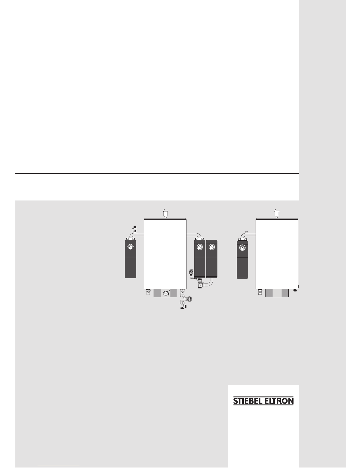
Buffer cylinder with booster heater ange/heat pump compact installation set
» SBP 100 Komfort
» sBp-HF
» WpK i-H e
» WpK i-p e
» WpK i-W e
» WpK i-V
0
bar
2
4
1
3
65°C
20
0
40
60
80
100
120
°C
20
0
40
60
80
100
120
°C
20
0
40
60
80
100
120
°C
2
Dimensions in mm
Inhalt
1 Operating instructions 3
2 Installation instructions SBP 100 Komfort 3
3
Installation instructions SBF-HF 5
4
Installation instructions WPKI-H E,
WPKI-P E, WPKI-W E 6
5 Installation instructions WPKI-H E
and WPKI-V 10
6 Specification 12
Warranty 13
Environment and recycling 13
26_03_01_0345
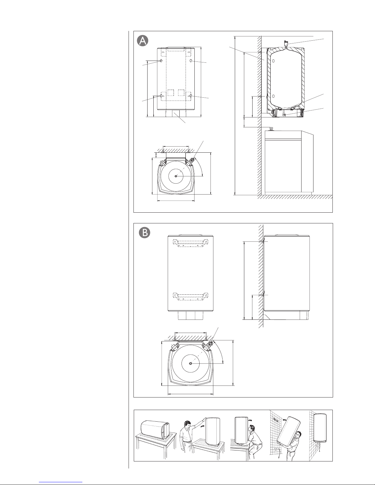
280
880
510
562
510
350
45 °
10
26_03_01_0340
min. 2200
8
1
9
5
4
510
2
7
562
510
350
6
3
955
880
280
ca.100
282
756
45 °
52
10
26_03_01_0337
Dimensions in mm
3
2 Installation instructions SBP 100 Komfort for heating contractors
Safety
Intended use
The sealed wall mounted cylinder with 100
l capacity acts as buffer cylinder for heat
pumps.
Observe the application limits listed in the
chapter „Specification / Data table“.
The appliance is intended for domestic use, i.e.
it can be used safely by untrained persons. The
appliance can also be used in a non-domestic
environment, e.g. in a small business, as long
as it is used in the same way.
Any other use beyond that described shall
be deemed inappropriate. Observation of
these instructions and of instructions for any
accessories used is also part of the correct use
of this appliance.
Subject to the relevant system, observe the
installation instructions of the components of
which the system comprises.
WARNING Injury
The appliance may be used by
children aged 8 and up and persons with
reduced physical, sensory or mental
capabilities or a lack of experience provided
that they are supervised or they have been
instructed on how to use the appliance safely
and have understood the resulting risks.
Children must never play with the appliance.
Children must never clean the appliance or
perform user maintenance unless they are
supervised.
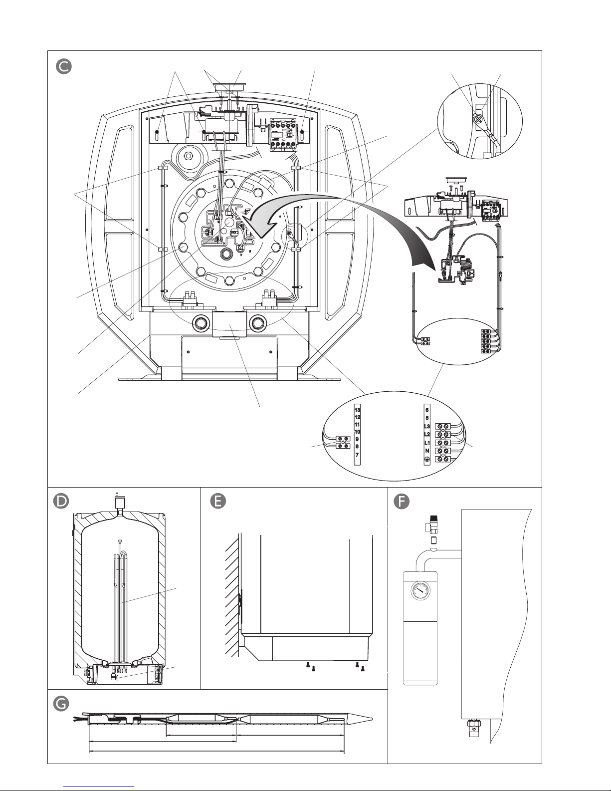
Equipment description
A buffer cylinder is recommended to ensure
trouble-free heat pump operation. In addition,
they are designed to separate both heat pump
and heating circuit volume flows.
Equipment layout
There are four G 1 ¼” equipment connections
at the back of the cylinder, which are
matched to the WPKI- .... heat pump compact
installation set.
A G 1/2” connection is provided at the top of
the equipment for the air vent valve supplied
with the cylinder.
At the bottom of the equipment, an aperture is
provided for the electric booster heater.
1 Air vent valve
2 G 1 ¼” flow connector heat pump
compact installation set
3 G 1 ¼” return connector heat
pump compact installation set
4 G 1 ¼” heating flow connector
5 G 1 ¼” heating return connector
6 Type plate SBP 100
7 Cleaning aperture
8 Fill & drain valve
9 Panel
10 Connector with sensor well for return
temperature sensor
Special accessories
Heat pump compact installation sets
The heat pump compact installation sets
WPKI-P, WPKI-H, WPKI-W and WPKI-V are
components of the heat pump system and are
specifically designed for the SBP 100 buffer
cylinder.
Keep these instructions safely and
pass them on to any new user, should
the equipment change hands. Let your
contractor check their content in conjunction
with any maintenance or repair work.
1 Operating instructions for users and contractors
Safety
Only a qualified contractor should carry out
installation, commissioning, maintenance and
repair of the appliance.
General safety instructions
We guarantee trouble-free function and
operational reliability only if the original
accessories and spare parts intended for the
appliance are used.
Instructions, standards and regulations
Observe all applicable national and
regional regulations and instructions.
Transport and packaging
This wall mounted cylinder can be transported
vertically or horizontally.
To prevent cylinder damage, remove
the packaging only at the place of
installation.
Place of installation
The installation location should be protected
from frost. If the system is not in use at times
when a frost is likely, drain the cylinder and all
connected systems to prevent damage.
The room must be at least 2.2 m high.
Ensure that the wall at the installation location
is capable of bearing the full weight of the
cylinder. Install the cylinder vertically, as
shown in and .
Cylinder installation
Prior to fitting the cylinder to the wall, insert
the connector with the sensor well for the
return temperature sensor into the cylinder
body
-10 and -10.
It is recommended that the components in the
WPKl set and the respective circulation pump
are fitted to the cylinder and hand tightened
before the installation.
Fit the heat pump compact installation set
with circulation pumps (see page 6 section
3 “Installation instructions for accessories
WPKI-P, WPKI-H, WPKI-W” and page 11
section 4 “Installation instructions for
accessory WPKI-V”.
Fit the wall mounting panel or mounting
brackets to the respective wall and hook the
cylinder into one or the other fitting.
Observe the gap between the heat
pump and the cylinder .
Select fixing materials in accordance with the
wall construction/condition.
Fit the air vent valve into the top of
the cylinder
-1.
Maintenance
Regularly vent the safety valve until water
streams from it. Close the safety valve after
checking.
Commissioning
(only by a qualified contractor)
1. Fill and vent the cylinder.
2. Check the safety valve function.
Water connection
For connector allocation, see equipment
layout.
Implement the water connections in
accordance with the installation drawings in
the heat pump installation instructions.
For filling, venting and draining the
system, open the non-return valves
of the heat pump compact installation
set, i.e. set them to
. Then return them
into position
. The setting screw of the
WPKI-H non-return valve is located behind
the thermometer.
4
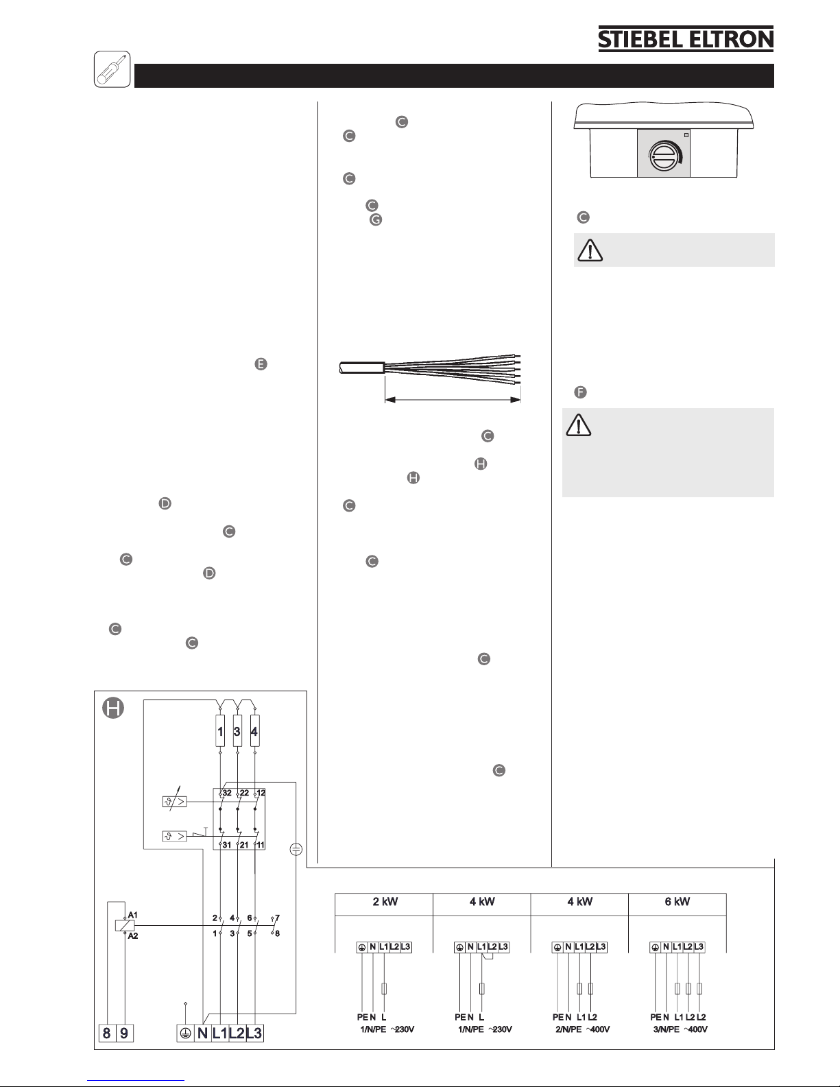
21
8
4
9
7
6 5
2
11
600
710
78.5 110
High limit safety cut-out Controller
1
13
C26_03_01_0336
13
8
10
12
C26_03_01_0339
26_03_01_0342
C26_03_01_0341
D0000035884
20
0
40
60
80
100
120
°C
5
Installing the electric booster heater
SBP-HF Part no. 074252
Instructions and regulations
– DIN VDE 100
– DIN VDE 0701
– Regulations of your local electricity supply
company
– The equipment type plate
The wall mounted cylinder with electric
booster heater is only designed for a
permanently connected power supply in
conjunction with the knock-out cable entry.
The equipment must be able to be separated
from the mains supply, for example by fuses,
which disconnect all poles with at least 3 mm
contact separation.
Fitting the booster heater flange:
– Open the control chamber lid (
).
– When retrofitting the heater:
Drain the water from the cylinder,
release the pipe fittings and remove the
equipment from the wall.
– Remove the drain valve (to be re-used).
– Remove the flange plate. The semi-shells,
pressure plate and insulating plate will
be re-used.
– Install the booster heater flange into the
cylinder ( ), use new gaskets, push on
the insulating plate, position the pressure
plate inside the recess ( -12) of the
plastic casing, and tighten 10 screws
( -4) with 8 Nm.
– Fit the drain valve ( -2) with a new
flange gasket and tighten with 20 Nm.
Fit the wiring set:
– Fit the component support with 3 screws
( -1).
– Fit the terminals ( -5 and 6).
– Secure the earth strap with a self-tapping
screw (M5) (
-9) on the cylinder tab
( -10).
– Secure the straps in the strap holders
( -8).
– Insert the controller bulbs into the sensor
pipe ( -11) until the limiter clicks into
place ( ).
– Push the red plug onto the booster heater
flange.
Mount the cylinder on the wall.
Install the heat pump compact installation
set WPKI-...
Fill the cylinder or the complete system with
water.
Power supply preparation
250 mm
26_03_01_0338
Route the power supply cable through the
PG21 fitting of the strain relief ( -7) and
connect in accordance with the connection
diagram (see wiring diagram ) at the
terminal strip ( -5).
Remove the knock-out in the strain relief
( -7) for the control cable from the heat
pump manager, and route the control
cable via the PG11 fitting into the cylinder.
Connect the control cable at the terminal
strip ( -6) at terminals 8-9.
Control chamber cover
– Remove the adhesive cover strip.
– Affix a new adhesive cover strip and push
firmly down.
– Affix the wiring diagram pad to the
interior of the control chamber cover.
– Undo the controller screws ( -2) from
the support and remove the temperature
selector (to be re-used later).
– Position the control chamber cover and
secure with 4 screws.
– Secure the controller to the control
chamber cover with the previously
undone screws.
– Push the temperature selector ( -3)
onto the controller axis.
26_03_01_0343
65°C
– Affix the rating plate of the booster heater
flange set on the l.h. side of the casing
( -13) and tick the selected output.
Install the safety valve into the
heating flow.
The safety valve must not be able to be
closed towards the cylinder.
The blow-off aperture of the safety valve
must remain open towards the atmosphere.
When using the heat pump compact
installation set WPKI-H, the safety valve can
be inserted into the threaded hole provided
for this purpose in the upper pipe bend (
).
Before and after fitting the control
chamber cover, the contractor must
carry out the following checks in accordance
with DIN VDE 0701
[or local regulations] after fitting the electric
booster heater:
Visual inspection of:
– The condition and security of the control
chamber cover, the adhesive strip and
the temperature selector.
– Connecting cables.
– Strain relief and cable routing.
– Cable routing.
– Positioning of the capillary tubes from
the temperature controller and the
temperature limiter.
Check the earth connection
Check the ionisation resistance
Check the system for leaks
Check the safety valve function
Check the safety labels
Function check
Check the heating up and the first
switching of the temperature controller.
26_03_01_0344
3 Installation instructions SBF-HF for heating contractors
 Loading...