

STIEBEL ELTRON SBB 300 WP Trend, SBB 400 WP Trend, SBB 500 WP Trend Operation And Installation
BEDIENUNG UND INSTALLATION
OPERATION AND INSTALLATION
UTILISATION ET INSTALLATION
BEDIENING EN INSTALLATIE
ANVÄNDNING OCH INSTALLATION
OBSLUHA A INSTALACE
OBSŁUGA I INSTALACJA
KEZELÉS ÉS TELEPÍTÉS
ЭКСПЛУАТАЦИЯ И МОНТАЖ
KÄYTTÖ JA ASENNUS
Warmwasser-Standspeicher für Wärmepumpen | Floorstanding DHW cylinder for heat
pumps | Ballon d‘eau chaude sanitaire sur socle pour pompes à chaleur | Staande
warmwaterboiler voor warmtepompen | Stående ackumulatortank för varmvatten
för värmepumpar | Stojatý zásobník teplé vody pro tepelná čerpadla | Stojący
zasobnik c.w.u do pomp ciepła | Álló melegvíztartály hőszivattyúkhoz | Напольный
накопительный водонагреватель для тепловых насосов| Lattiamalliset lämminvesivaraajat
lämpöpumpuille
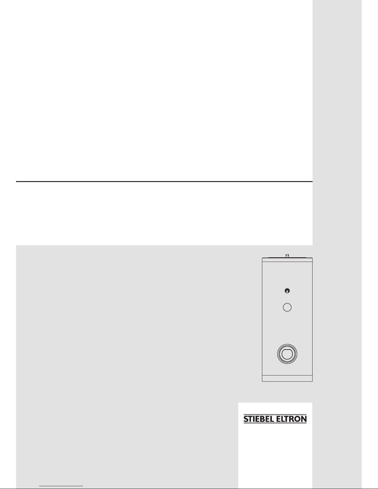
» SBB 300 WP Trend
» SBB 400 WP Trend
» SBB 500 WP Trend
ENGLISH
www.stiebel-eltron.com SBB WP Trend | 13
CONTENTS | OPERATION
General information
OPERATION
1. General information ��������������������������������������� 13
1.1 Safety instructions ����������������������������������������������13
1.2 Other symbols in this documentation ���������������������� 13
1.3 Units of measurement ����������������������������������������� 14
2. Safety �������������������������������������������������������� 14
2.1 Intended use ����������������������������������������������������� 14
2.2 Safety instructions ����������������������������������������������14
2.3 Test symbols ����������������������������������������������������� 14
3. Appliance description ������������������������������������� 14
4. Cleaning, care and maintenance ������������������������� 14
4.1 Scaling ������������������������������������������������������������ 14
5. Troubleshooting �������������������������������������������� 14
INSTALLATION
6. Safety �������������������������������������������������������� 15
6.1 General safety instructions ����������������������������������� 15
6.2 Instructions, standards and regulations ������������������� 15
7. Appliance description ������������������������������������� 15
7.1 Required accessories ������������������������������������������15
7.2 Further accessories���������������������������������������������15
8. Preparations ������������������������������������������������ 15
8.1 Installation site �������������������������������������������������� 15
8.2 Transport ��������������������������������������������������������� 15
9. Installation �������������������������������������������������� 16
9.1 Removing / fitting the cylinder casing ��������������������� 16
9.2 Indirect coil connection ���������������������������������������� 16
9.3 Water connection and safety assembly �������������������� 16
9.4 Temperature sensors������������������������������������������� 16
10. Commissioning ��������������������������������������������� 17
10.1 Initial start-up ��������������������������������������������������� 17
10.2 Recommissioning ����������������������������������������������� 17
11. Shutting down the system �������������������������������� 17
12. Troubleshooting �������������������������������������������� 17
13. Maintenance ������������������������������������������������ 17
13.1 Checking the safety valve ������������������������������������� 17
13.2 Checking / replacing the protective anode ���������������� 17
13.3 Draining the appliance ���������������������������������������� 17
13.4 Cleaning and descaling the appliance ���������������������� 17
14. Specification ������������������������������������������������ 18
14.1 Dimensions and connections ��������������������������������� 18
14.2 Details on energy consumption ������������������������������ 21
14.3 Data table �������������������������������������������������������� 21
GUARANTEE
ENVIRONMENT AND RECYCLING
OPERATION
1. General information
The chapter "Operation" is intended for appliance users and qualified contractors.
The chapter "Installation" is intended for qualified contractors.
Note
Read these instructions carefully before using the appliance and retain them for future reference.
Pass on the instructions to a new user if required.
1.1 Safety instructions
1.1.1 Structure of safety instructions
!
KEYWORD Type of risk
Here, possible consequences are listed that may result
from failure to observe the safety instructions.
Steps to prevent the risk are listed.
1.1.2 Symbols, type of risk
Symbol Type of risk
Injury
Electrocution
Burns
(burns, scalding)
1.1.3 Keywords
KEYWORD Meaning
DANGER Failure to observe this information will result in serious
injury or death.
WARNING Failure to observe this information may result in serious
injury or death.
CAUTION Failure to observe this information may result in non-seri-
ous or minor injury.
1.2 Other symbols in this documentation
Note
General information is identified by the symbol shown
on the left.
Read these texts carefully.
!
OPERATION
Safety
14 | SBB WP Trend www.stiebel-eltron.com
Symbol Meaning
Material losses
(appliance damage, consequential losses and environmental pollution)
Appliance disposal
This symbol indicates that you have to do something. The ac-
tion you need to take is described step by step.
1.3 Units of measurement
Note
All measurements are given in mm unless stated otherwise.
2. Safety
2.1 Intended use
The appliance is intended for domestic use. It can be used safely
by untrained persons. The appliance can also be used in a non-domestic environment, e.g. in a small business, as long as it is used
in the same way.
This appliance is designed to heat DHW with heat pumps.
Any other use beyond that described shall be deemed inappropri-
ate. Observation of these instructions and of instructions for any
accessories used is also part of the correct use of this appliance.
2.2 Safety instructions
WARNING Burns
There is a risk of scalding at outlet temperatures in excess of 43 °C.
!
WARNING Injury
The appliance may be used by children aged 8 and up and
persons with reduced physical, sensory or mental capabilities or a lack of experience and know-how, provided
that they are supervised or they have been instructed on
how to use the appliance safely and have understood
the resulting risks. Children must never play with the
appliance. Children must never clean the appliance or
perform user maintenance unless they are supervised.
!
Material losses
The appliance is pressurised.
During the heat-up process, expansion water will drip
from the safety valve. If water continues to drip when
heating is completed, please inform your qualified contractor.
2.3 Test symbols
See type plate on the appliance.
3. Appliance description
The DHW is heated via a smooth tube internal indirect coil. In
addition, a threaded immersion heater can be connected. You
can use the appliance to supply one or several draw-off points.
The appliance is equipped with an inspection flange and thermometer.
The steel cylinder is coated on the inside with special directly applied “anticor
®
” enamel and is equipped with a protective anode.
This anode protects the inside of the cylinder from corrosion. The
cylinder is surrounded by foam insulation and a plastic jacket.
4. Cleaning, care and maintenance
Have the function of the safety assembly and electrical safe-
ty of the fitted accessories regularly checked by a qualified
contractor.
Have the protective anode checked by a qualified contractor
after the first two years of use. The qualified contractor will
then determine the intervals at which it must be checked
thereafter.
Never use abrasive or corrosive cleaning agents. A damp
cloth is sufficient for cleaning the appliance.
4.1 Scaling
Almost every type of water will deposit lime at high temperatures.
This settles inside the appliance and affects both the performance
and service life. If a threaded immersion heater is installed, the
heating elements must be descaled from time to time. A qualified
contractor who knows the local water quality will tell you when
the next service is due.
Check the taps regularly. Limescale deposits at the spouts
can be removed using commercially available descaling
agents.
5. Troubleshooting
Problem Cause Remedy
The flow rate is low. The aerator in the tap or
the shower head is scaled
up or contaminated.
Clean and/or descale the
aerator or shower head.
If you cannot remedy the fault, notify your qualified contractor.
To facilitate and speed up your enquiry, please provide the serial
number from the type plate (no. 000000-0000-000000):
Nr. 000000-0000-000000
D0000063493
!
ENGLISH
www.stiebel-eltron.com SBB WP Trend | 15
INSTALLATION
Safety
INSTALLATION
6. Safety
Only a qualified contractor should carry out installation, commissioning, maintenance and repair of the appliance.
6.1 General safety instructions
We can only guarantee trouble-free function and operational reliability if original spare parts intended for the appliance are used.
6.2 Instructions, standards and regulations
Note
Observe all applicable national and regional regulations
and instructions.
7. Appliance description
7.1 Required accessories
Depending on the static pressure, safety assemblies and pressure
reducing valves are available. These type-tested safety assemblies
protect the appliance against unacceptable excess pressure.
7.2 Further accessories
Threaded immersion heaters are available as accessories.
If it is not possible to insert a rod anode from above, install a
segmented anode.
8. Preparations
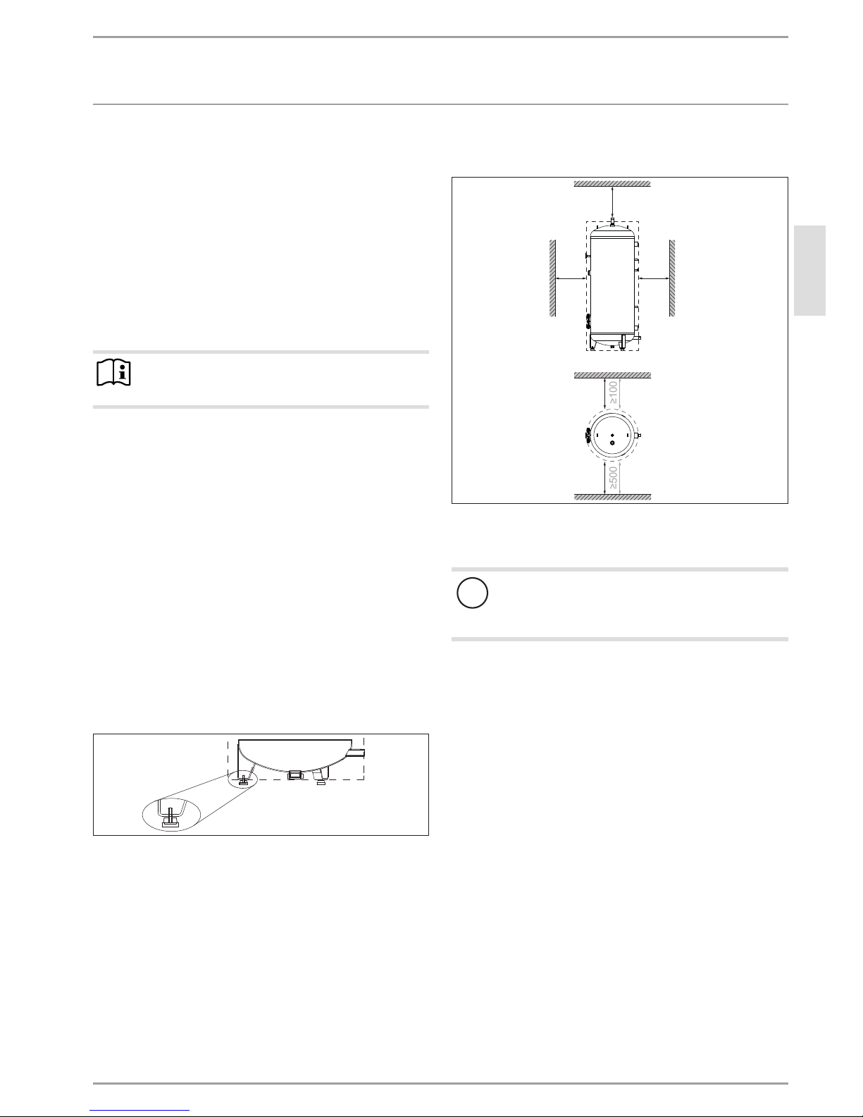
8.1 Installation site
Always install the appliance in a room free from the risk of
frost and near the draw-off point.
26�05�20�0004
Ensure the floor is level. Use the adjustable feet to compen-
sate for any unevenness in the floor.
Ensure the floor has a sufficient load bearing capacity (see
chapter "Specification / Data table").
Observe the room height and height when tilted (see chapter
"Specification / Data table").
Minimum clearances
The minimum side clearances can be swapped to left or right.
≥300
≥300≥800
≥500
≥100
≥100
≥500
D0000059973
Maintain the minimum clearances.
8.2 Transport
!
Material losses
We recommend removing the cylinder casing for transportation to the installation location to prevent it from
becoming dirty or damaged.
For transportation, the appliance is secured to the pallet with
metal brackets.
Remove the screws from the pallet.
Turn the metal brackets to the inside of the adjustable feet
under the appliance.
 Loading...