

STIEBEL ELTRON SBB 300 plus, SBB 600 plus, SBB 400 plus Operation And Installation
BEDIENUNG UND INSTALLATION
OPERATION AND INSTALLATION
Solar -Warmwasserspeicher |
» SBB 300 plus
» SBB 400 plus
» SBB 600 plus
DHW tank for solar systems
CONTENTS | SPECIAL INFORMATION
General information
OPERATION
1. General information ��������������������������������������� 15
1.1 Safety instructions ���������������������������������������������� 15
1.2 Other symbols in this documentation ���������������������� 16
1.3 Units of measurement ����������������������������������������� 16
2. Safety �������������������������������������������������������� 16
2.1 Intended use ����������������������������������������������������� 16
2.2 Safety instructions ����������������������������������������������16
3. Appliance description ������������������������������������� 16
4. Cleaning, care and maintenance ������������������������� 17
4.1 Signal anode with consumption indicator ����������������� 17
4.2 Scaling ������������������������������������������������������������ 17
5. Troubleshooting �������������������������������������������� 17
OPERATION
1. General information
The chapter "Operation" is intended for appliance users and qualified contractors.
The chapter "Installation" is intended for qualified contractors.
Note
Read these instructions carefully before using the appliance and retain them for future reference.
Pass on the instructions to a new user if required.
ENGLISH
INSTALLATION
6. Safety �������������������������������������������������������� 18
6.1 General safety instructions ����������������������������������� 18
6.2 Instructions, standards and regulations ������������������� 18
7. Appliance description ������������������������������������� 18
7.1 Standard delivery ����������������������������������������������� 18
7.2 Accessories �������������������������������������������������������18
8. Preparations ������������������������������������������������ 18
8.1 Installation site �������������������������������������������������� 18
8.2 Transport ��������������������������������������������������������� 19
9. Installation �������������������������������������������������� 19
9.1 Cylinder casing �������������������������������������������������� 19
9.2 Signal anode ����������������������������������������������������� 19
9.3 Solar or heating installation ���������������������������������� 19
9.4 Water connection and safety assembly �������������������� 20
9.5 Sensor DHW ������������������������������������������������������ 20
9.6 Sensor solar cylinder ������������������������������������������20
9.7 Thermometer ���������������������������������������������������� 21
10. Commissioning ��������������������������������������������� 21
10.1 Initial start-up ��������������������������������������������������� 21
10.2 Recommissioning ����������������������������������������������� 21
11. Shutdown ��������������������������������������������������� 21
12. Maintenance ������������������������������������������������ 21
12.1 Draining the appliance ����������������������������������������21
12.2 Checking the safety valve ������������������������������������� 21
12.3 Replacing the signal anode ����������������������������������� 21
12.4 Cleaning and descaling the appliance ���������������������� 21
13. Specification ������������������������������������������������ 22
13.1 Dimensions and connections ��������������������������������� 22
13.2 Details on energy consumption ������������������������������ 26
13.3 Specification ����������������������������������������������������� 26
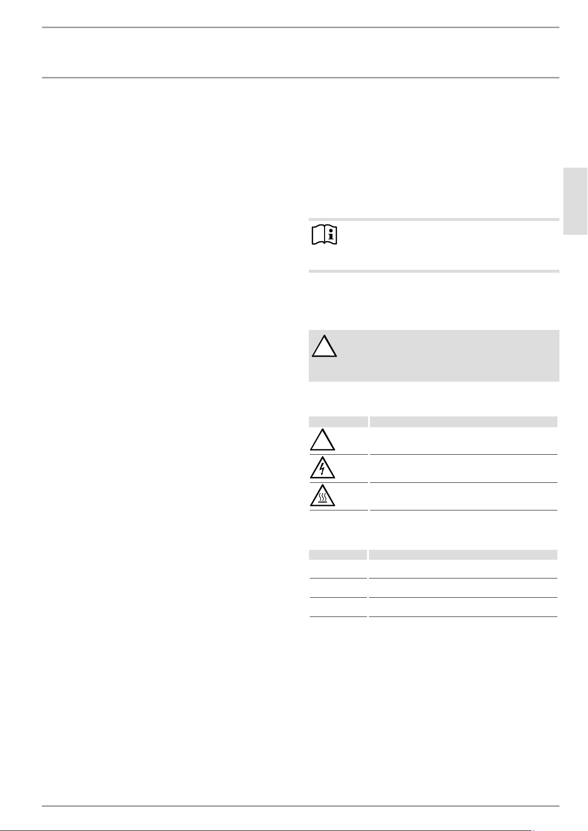
1.1 Safety instructions
1.1.1 Structure of safety instructions
KEYWORD Type of risk
!
Here, possible consequences are listed that may result
from failure to observe the safety instructions.
Steps to prevent the risk are listed.
1.1.2 Symbols, type of risk
Symbol Type of risk
!
1.1.3 Keywords
KEYWORD Meaning
DANGER Failure to observe this information will result in serious
WARNING Failure to observe this information may result in serious
CAUTION Failure to observe this information may result in non-seri-
Injury
Electrocution
Burns
(burns, scalding)
injury or death.
injury or death.
ous or minor injury.
GUARANTEE
ENVIRONMENT AND RECYCLING
www.stiebel-eltron.com SBB 300-600 plus | 15
OPERATION
Safety
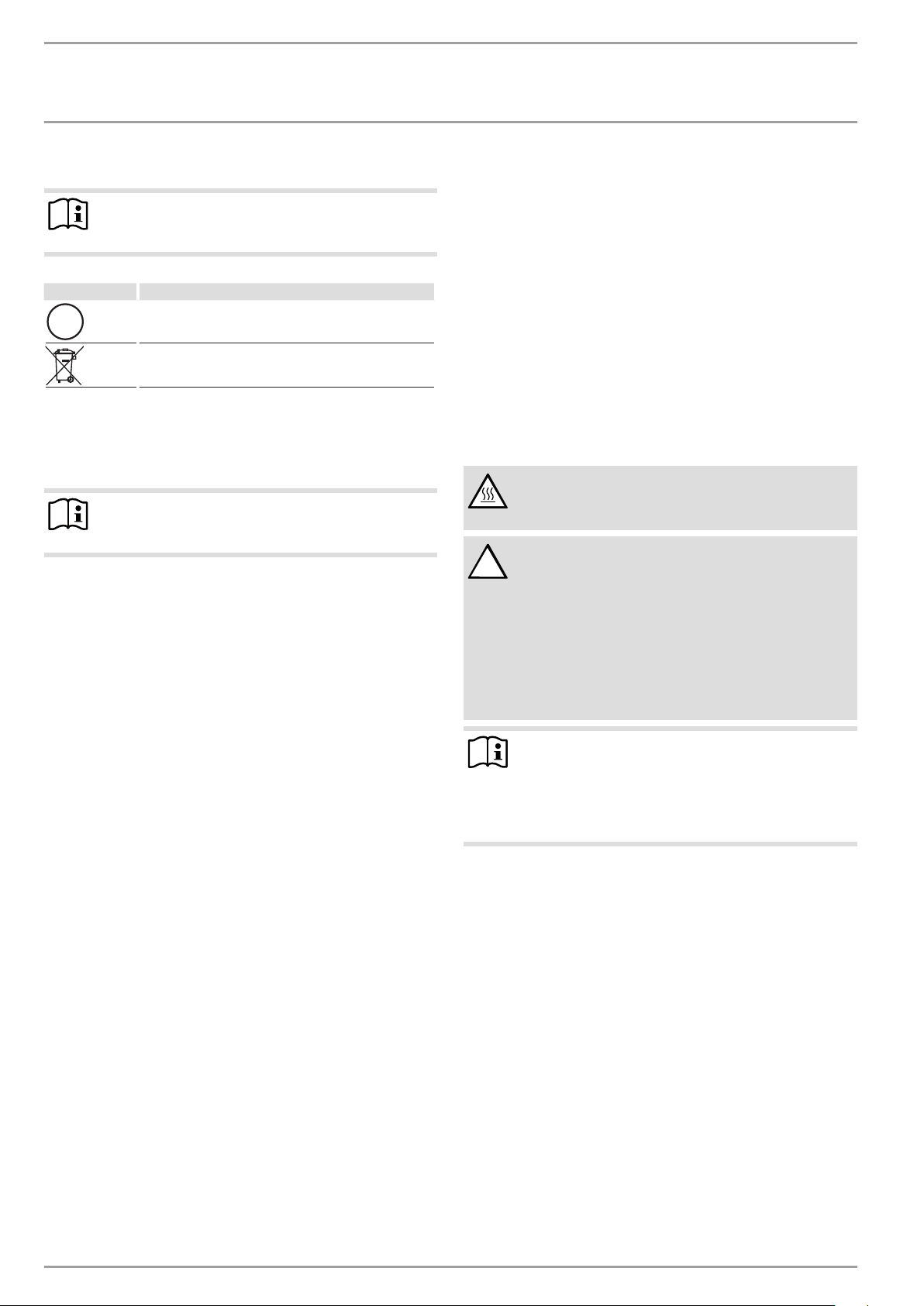
1.2 Other symbols in this documentation
Note
General information is identified by the adjacent symbol.
Read these texts carefully.
Symbol Meaning
!
This symbol indicates that you have to do something. The ac-
tion you need to take is described step by step.
Material losses
(appliance damage, consequential losses and environmental pollution)
Appliance disposal
1.3 Units of measurement
Note
All measurements are given in mm unless stated otherwise.
2. Safety
2.1 Intended use
The appliance is intended for heating domestic hot water in conjunction with solar collectors and optionally with further heat
sources for reheating the upper half of the cylinder.
This appliance is intended for domestic use. It can be used safely
by untrained persons. The appliance can also be used in a non-domestic environment, e.g. in a small business, as long as it is used
in the same way.
Any other use beyond that described shall be deemed inappropriate. Observation of these instructions and of instructions for any
accessories used is also part of the correct use of this appliance.
2.2 Safety instructions
WARNING Burns
There is a risk of scalding at outlet temperatures in excess of 43°C.
WARNING Injury
!
The appliance may be used by children aged 8 and older
and persons with reduced physical, sensory or mental
capabilities or a lack of experience and know-how, provided that they are supervised or they have been instructed on how to use the appliance safely and have
understood the resulting risks. Children must never play
with the appliance. Children must never clean the appliance or perform user maintenance unless they are
supervised.
Note
The appliance is pressurised.
During the heat-up process, expansion water will drip
from the safety valve. If water continues to drip when
heating is completed, please inform your qualified contractor.
3. Appliance description
The DHW is heated via two smooth tube internal indirect coils. In
addition, a threaded immersion heater and/or flanged immersion
heater or heat exchanger can be connected. You can use the appliance to supply one or several draw-off points.
The appliance is equipped with an inspection flange and thermometer.
The steel cylinder is coated on the inside with special directly
applied enamel and is equipped with a signal anode. The anode
with consumption indicator protects the cylinder interior from
corrosion. The cylinder is surrounded by foam insulation and a
cylinder jacket.
16 | SBB 300-600 plus www.stiebel-eltron.com
OPERATION
Cleaning, care and maintenance
4. Cleaning, care and maintenance
Have the function of the safety assembly and electrical safe-
ty of the fitted accessories regularly checked by a qualified
contractor.
Have the protective anode checked by a qualified contractor
after the first two years of use. The qualified contractor will
then determine the intervals at which repeat checks should
be performed.
Never use abrasive or corrosive cleaning agents. A damp
cloth is sufficient for cleaning the appliance.
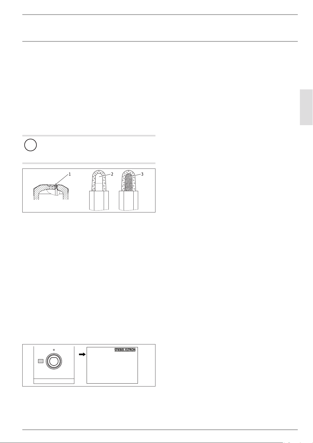
4.1 Signal anode with consumption indicator
Material losses
!
If the consumption indicator changes colour from white
to red, have the signal anode checked by a qualified contractor and if necessary replaced.
ENGLISH
1
1 Signal anode with consumption indicator
2 White = Anode OK
3 Red = Requires checking by heating contractor
2
3
4.2 Scaling
Almost every type of water will deposit limescale at high temperatures. This settles inside the appliance and affects both the
performance and service life. If a threaded immersion heater or
flanged immersion heater is fitted, the heating elements must
be descaled from time to time. A qualified contractor who knows
the local water quality will tell you when the next service is due.
Check the taps regularly. Limescale deposits at the tap out-
lets can be removed using commercially available descaling
agents.
5. Troubleshooting
Call your qualified contractor.
To facilitate and speed up your enquiry, please provide the serial
number from the type plate (000000-0000-000000):
26�03�20�0001
Nr. 000000-0000-000000
D0000063493
www.stiebel-eltron.com SBB 300-600 plus | 17
INSTALLAT ION
Safety
INSTALLATION
6. Safety
Only a qualified contractor should carry out installation, commissioning, maintenance and repair of the appliance.
6.1 General safety instructions
We can only guarantee trouble-free function and operational reliability if original spare parts intended for the appliance are used.
6.2 Instructions, standards and regulations
Note
Observe all applicable national and regional regulations
and instructions.
7. Appliance description
7.1 Standard delivery
The following are delivered with the appliance:
- Sensor DHW
- Fixing straps with closure elements
- Thermometer (located in the DHW outlet on delivery)
- Label "Signal anode information"
- Adaptor with flat gasket for connecting a DHW circulation line
8. Preparations
8.1 Installation site
Always install the appliance in a room free from the risk of
frost and near the draw-off point.
Ensure the floor has sufficient load bearing capacity and
evenness (see chapter “Specification / Data table”).
Observe the room height and height when tilted (see chapter
"Specification/ Data table").
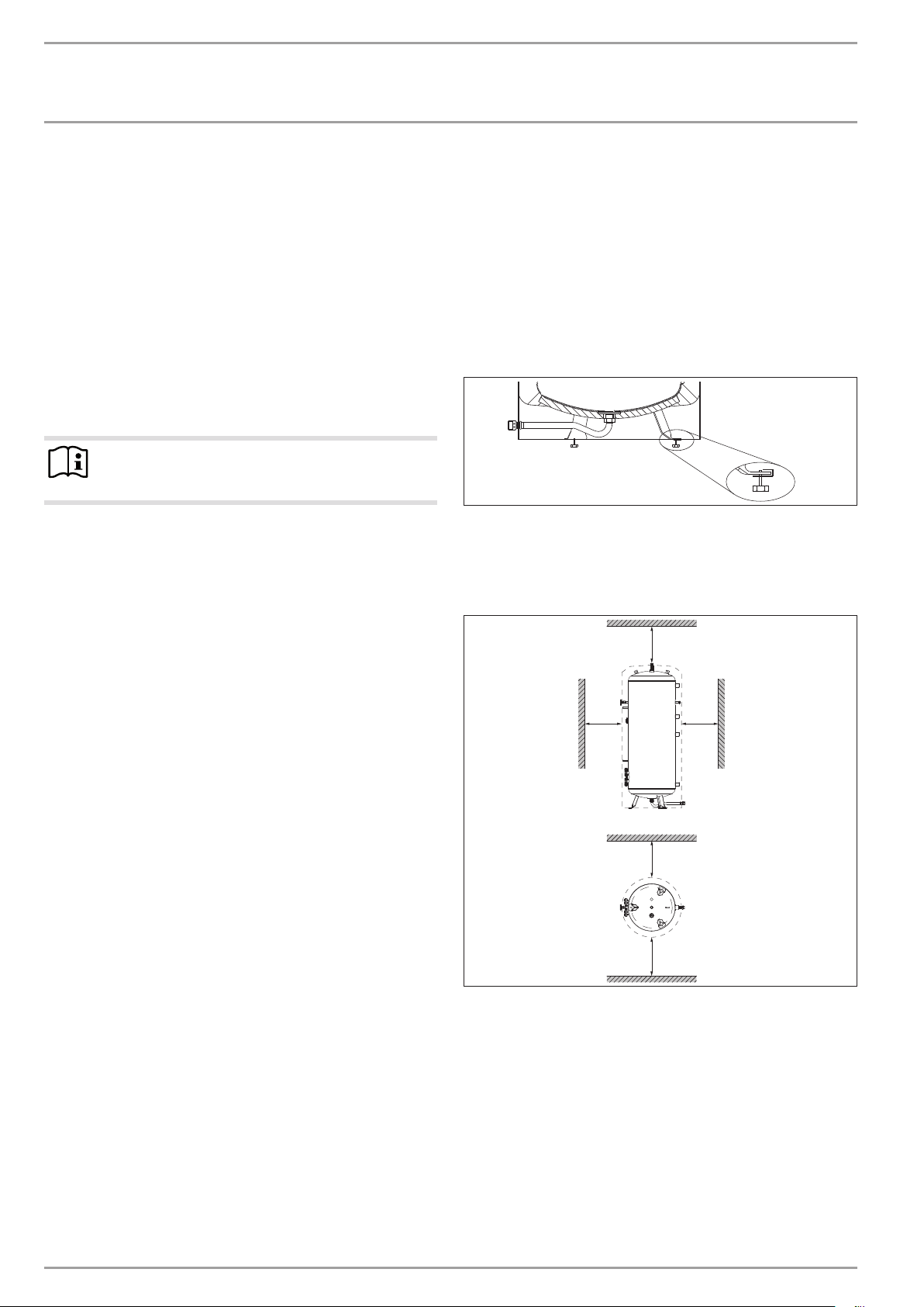
SBB 300-400 plus
26�03�20�0008
Use the adjustable feet to compensate for any unevenness in
the floor.
Minimum clearances
The minimum side clearances can be swapped to left or right.
≥300≥800
SBB 300-400 plus
- Cold water inlet pipe with flat gasket
- Adjustable feet
7.2 Accessories
Required accessories
Safety assemblies and pressure reducing valves are available
to suit the prevailing supply pressure. These type-tested safety
assemblies protect the appliance against impermissible excess
pressure.
Further accessories
Threaded immersion heaters, flanged immersion heaters and internal indirect coils are available as accessories.
≥500 ≥300
≥100
Maintain the minimum clearances.
D0000060125
18 | SBB 300-600 plus www.stiebel-eltron.com
 Loading...