

STIEBEL ELTRON MINI 2.5-1, MINI 3-1, MINI 3.5-1, MINI 4-2, MINI 6-2 Operation And Installation
...
OPERATION AND INSTALLATION
FUNCIONAMIENTO E INS TAL AC IÓN
MODE D’EMPLOI ET INSTALLATION
TANKLESS ELECTRIC WATER HEATER WITH ELECTROMECHANICAL FLOW SWITCH
CALENTADOR ELÉCTRICO DE AGUA SIN TANQUE CON SENSOR ELECTROMECÁNICO DE FLUJO
CHAUFFE-EAU ÉLECTRIQUE SANS RÉSERVOIR AVEC CONTACTEUR DEBITMETRIQUE
ÉLECTROMÉCANIQUE
» MINI™ 2-1
» MINI™ 2.5-1
» MINI™ 3-1
» MINI™ 3.5-1
» MINI™ 4-2
» MINI™ 6-2
Conforms to ANSI/UL Std. 499
Certifi ed to CAN/CSA Std. E335-1 & E335-2-35
Conforme a ANSI/UL Std. 499
Certifi cación con CAN/CSA Std. E335-1 & E335-2-35
Conforme à la norme ANSI/UL Std. 499
Certifi é à la norme CAN/CSA Std. E335-1 & E335-2-35
Tested and certifi ed by WQA to NSF/ANSI372
for lead free compliance.
Probado y certifi cado por WQA NSF/ANSI 372 para
el cumplimiento de las regulaciones sin plomo.
Testé et certifi é par WQA à la NSF/ANSI 372 pour une
utilisation sans plomb.
CONTENTS | OPERATION
poppo
pppo
ppwer
GENERAL INFORMATION
1. General Information __________________________________________ 2
1.1 Symbol key ___________________________________________________________ 2
2. Safety precautions ____________________________________________ 3
3. Register your product ________________________________________3
4. Temperature increase above ambient water temperature 4
5. Technical drawings ___________________________________________ 4
6. Overview ______________________________________________________ 6
6.1 General Description ________________________________________________ 6
6.2 Important information before supplying power to unit_____ 6
6.3 Hot water output at max rated voltage _________________________ 6
6.4 Incorrect use _________________________________________________________ 7
6.5 First steps to be taken in the event of malfunction __________7
6.6 Maintenance and care _____________________________________________ 7
7. Installation instructions ______________________________________ 7
7.1 Mounting the unit __________________________________________________ 7
7.2 Plumbing connections _____________________________________________ 7
7.3 Electrical connection _______________________________________________ 8
8. Initial start-up ________________________________________________8
9. Water heater hand over ______________________________________ 8
10. Normal maintenance _________________________________________ 8
11. Technical data _________________________________________________ 9
12. Troubleshooting _______________________________________________ 9
13. Spare parts ___________________________________________________10
14. Warranty _____________________________________________________11
THIS IS THE SAFETY ALERT SYMBOL. IT IS USED TO ALERT
!
YOU TO POTENTIAL PERSONAL INJURY HAZARD. OBEY
ALL SAFETY MESSAGES THAT FOLLOW THIS SYMBOL TO AVOID
POSSIBLE INJURY OR DEATH.
The chapter Operation is intended for homeowners, heating
contractors, plumbers and electricians.
The chapter Installation is intended for heating contractors,
plumbers and electricians only.
1.1 Symbol key
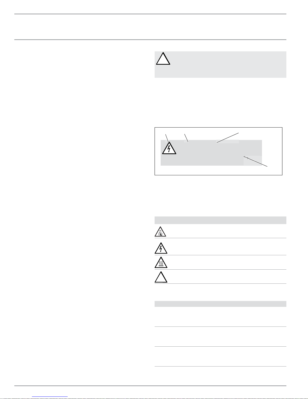
1.1.1 Layout of safety information
1
2
DANGER Electric shock
Before any work on the appliance,
disconnect all poles from the power
supply.
3
4
1 Symbol (see 1.1.2 “Symbols”, below)
2 Keyword (see 1.1.3 “Keywords”, below)
3 Description (see 1.1.2 “Symbols”, below)
4 Information text
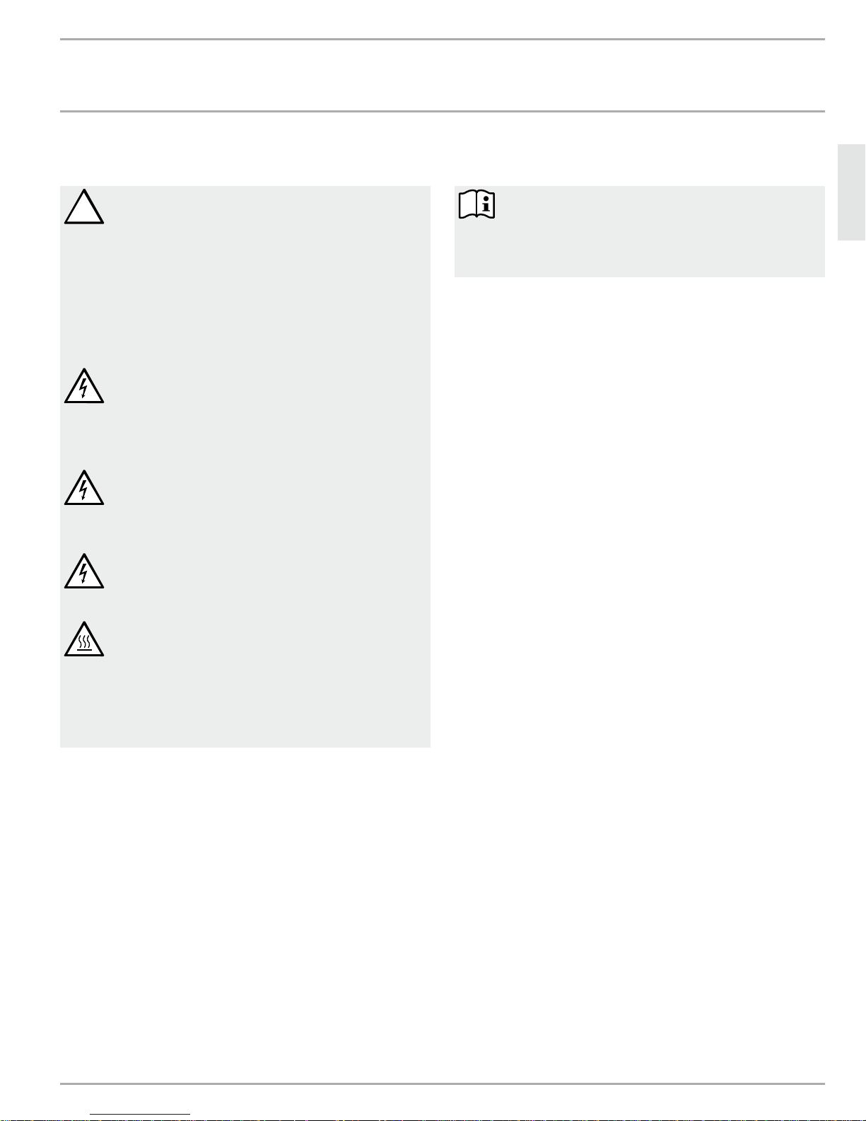
1.1.2 Symbols
1. General Information
Read this entire manual. Failure to follow all the guides, instructions
and rules could cause personal injury or property damage.
Improper installation, adjustment, alteration, service and use of
this unit can result in serious injury.
T his u ni t mu s t b e in s t al l ed b y a l ic ens e d el e c tr i ci an a n d p l um b er . T h e
installation must comply with all national, state and local plumbing
and electric codes. Proper installation is the responsibility of the
installer. Failure to comply with the installation and operating
instructions or improper use voids the warranty.
Save these instructions for future reference. Installer should leave
these instructions with the consumer.
If you have any questions regarding the installation, use or
operation of this water heater, or if you need any additional
installation manuals, please call our technical service line at 800582-8423 (USA and Canada only). If you are calling from outside
the USA or Canada, please call USA 413-247-3380 and we will refer
you to a qualifi ed Stiebel Eltron service representative in your area.
Symbol Description
Injury
Electrocution
Burns or scalding
!
Other situations
1.1.3 Keywords
KEYWORD
DANGER The keyword DANGER indicates information that
must be observed, otherwise serious injury or
death will result.
WARNING The keyword WARNING indicates information that
must be observed, otherwise serious injury or
death may result.
CAUTION The keyword CAUTION indicates information that
must be observed, otherwise relatively serious or
light injuries may result.
2 | MINI™ SERIES TANKLESS ELECTRIC WATER HEATERS WWW.STIEBEL-ELTRON-USA.COM
GENERAL INFORMATION | OPERATION
SAFETY PRECAUTIONS
2. Safety precautions
PLEASE READ AND FOLLOW THESE INSTRUCTIONS.
!
FAILURE TO FOLLOW THESE INSTRUCTIONS COULD
RESULT IN SERIOUS BODILY INJURY OR DEATH.
THE UNIT MUST BE INSTALLED BY A LICENSED ELECTRICIAN
AND PLUMBER. THE INSTALLATION MUST COMPLY WITH ALL
NATIONAL, STATE AND LOCAL PLUMBING AND ELECTRIC CODES.
SERVICE OF THE UNIT MUST BE PERFORMED BY QUALIFIED
SERVICE TECHNICIANS.
BEFORE PROCEEDING WITH ANY INSTALLATION,
ADJUSTMENT, ALTERATION, OR SERVICE OF THIS UNIT
ALL CIRCUIT BREAKERS AND DISCONNECT SWITCHES SERVICING
THE UNIT MUST BE TURNED OFF. FAILURE TO DO SO COULD
RESULT IN SERIOUS PERSONAL INJURY OR DEATH.
DANGER: NEVER REMOVE THE UNIT'S COVER UNLESS
THE ELECTRICITY SERVICING THE UNIT IS TURNED OFF.
FAILURE TO DO SO COULD RESULT IN PERSONAL INJURY OR
DEATH.
WARNING: THE UNIT MUST BE PROPERLY GROUNDED.
FAILURE TO ELECTRICALLY GROUND THE PRODUCT
COULD RESULT IN SERIOUS PERSONAL INJURY OR DEATH.
DANGER: WATER TEMPERATURES OVER 125°F CAN
CAUSE SEVERE BURNS INSTANTLY OR DEATH FROM
SCALDING. A HOT WATER SCALDING POTENTIAL EXISTS IF THE
THERMOSTAT ON THE UNIT IS SET TOO HIGH. HOUSEHOLDS
WITH SMALL CHILDREN, DISABLED OR ELDERLY PERSONS MAY
REQUIRE THAT THE THERMOSTAT BE SET AT 120°F OR LOWER TO
PREVENT POSSIBLE INJURY FROM HOT WATER.
3. Register your product
YOU MUST REGISTER THIS PRODUCT WITHIN 90 DAYS OF
PURCHASE ON OUR WEB SITE IN ORDER TO ACTIVATE THE
STANDARD WARRANTY OR TO BE ELIGIBLE FOR THE EXTENDED
WARRANTY. GO TO OUR WEB SITE AT WWW.STIEBEL-ELTRON-USA.
COM AND CLICK ON REGISTER YOUR PRODUCT.
Before beginning the registration process, we suggest that you
gather the necessary information which will be as follows:
Type, Example: Mini 3-1 (from the white label that is on the right
side of the unit)
Number listed after "Nr."
Place of Purchase
Purchase Date
First & Last Name
Email address
Physical Address
Phone Number
IF YOU HAVE ANY QUESTIONS CONCERNING THE REGISTRATION
PROCESS OR WARRANTY OPTIONS, PLEASE CONTACT STIEBEL
ELTRON USA DIRECTLY AT (800)-582-8423.
Limited liability warranty:
Stiebel Eltron, Inc. is not liable for damages to the unit, damage to
personal property, bodily injury, or loss of life due to the following
conditions:
- Non-observance of these instructions
- Incorrect use (heating any other liquid than water)
- Installation of the appliance by unqualifi ed personnel
- Unauthorized modifi cations
- Technical modifi cations
- Use of unauthorized spare parts
ENGLISH
WWW.STIEBEL-ELTRON-USA.COM MINI™ SERIES TANKLESS ELECTRIC WATER HEATERS | 3
THE THREE YEAR WARRANTY COVERS ALL PARTS BUT DOES NOT
COVER DAMAGE TO THE UNIT DUE TO HARD WATER (FOR THE
COMPLETE WARRANTY SEE SECTION 14, “WARRANTY”, PG. 11).
IF YOU KNOW OR SUSPECT THAT THE WATER IN YOUR AREA IS
HARD (HAS A HIGH MINERAL CONTENT), IT IS NECESSARY TO
INSTALL A WATER SOFTENING DEVICE TO AVOID DAMAGE TO THE
Mini™ UNIT.
GENERAL INFORMATION | OPERATION
TEMPERATURE INCREASE ABOVE AMBIENT WATER TEMPERATURE
4. Temperature increase above ambient water temperature
[ °F ]
Type kW GPM
0.32 0.42 0.48 0.5 0.69 0.85 1.06 1.14
Mini 2-1* 1.8 39 – – – – – – –
Mini 2.5-1
Mini 3-1
Mini 3.5-1
Mini 4-2
Mini 6-2
Type kW l/min
1.2 1.6 1.8 2.0 2.6 3.2 4.0 4.3
Mini 2-1* 1.8 22 – – – – – – –
Mini 2.5-1
Mini 3-1
Mini 3.5-1
Mini 4-2
Mini 6-2
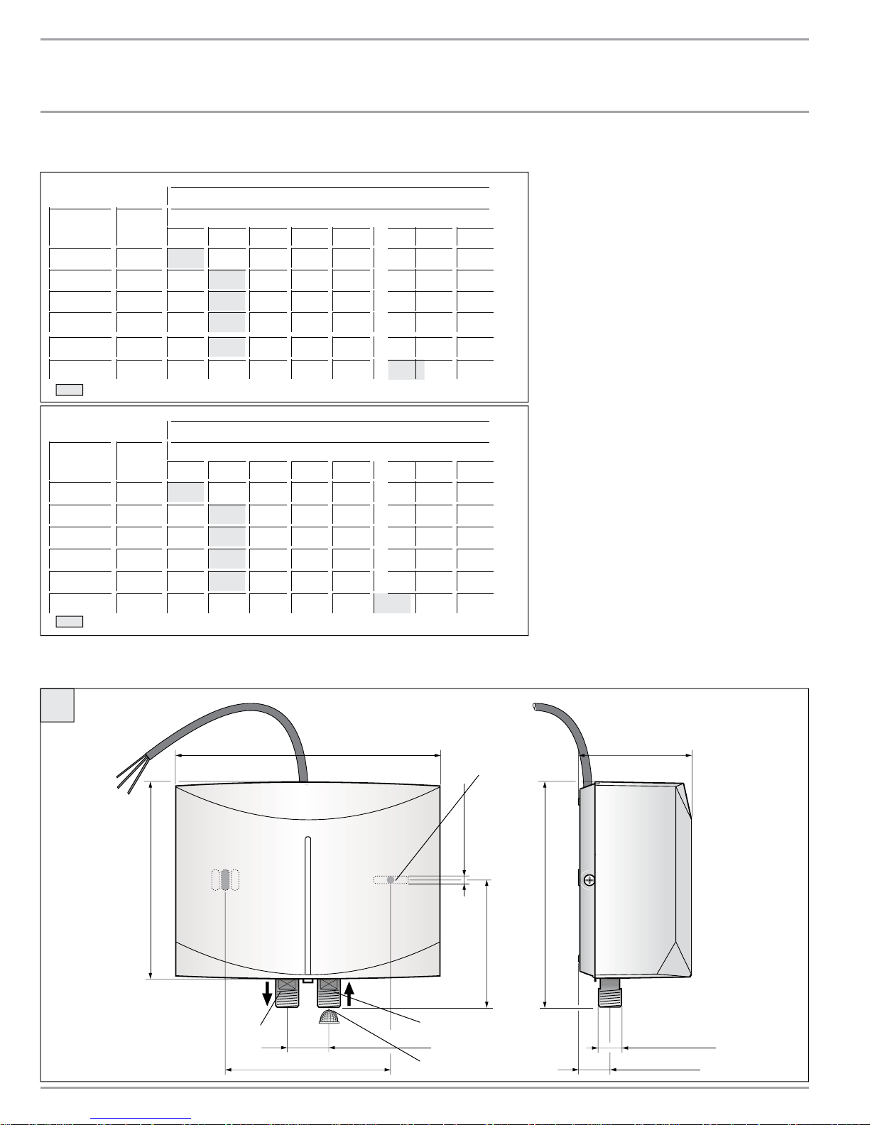
5. Technical drawings
2.4 – 39 34 33 24 – – –
3.0 – 49 43 41 30 – – –
3.5 – 57 50 45 35 – – –
3.5 – 57 50 45 35 – – –
5.7 – – – – – 46 37 34
Min. water fl ow to activate unit.
[ °C ]
2.4 – 22 19 17 13 – – –
3.0 – 27 24 22 17 – – –
3.5 – 31 28 25 19 – – –
3.5 – 31 28 25 19 – – –
5.7 – – – – – 26 20 19
Min. water fl ow to activate unit.
* Note: Mini 2-1 is internally restricted to 0.32 gpm (1.2 l/min)
* Note: Mini 2-1 is internally restricted to 0.32 gpm (1.2 l/min)
Figure A legend
1 Hot water connection
2 Cold water connection with fi lter screen
3 Filter screen
4 Mounting holes
A
7 ½ ” (190 mm) 3 ¼ ” (82 mm)
4
” (4,8 mm)
16
/
3
” (143 mm)
8
5
5/
mm)
3¾” (95
1
¾
” (120 mm)
4
3
1/
” (30 mm)
16
2
3
4 | MINI™ SERIES TANKLESS ELECTRIC WATER HEATERS WWW.STIEBEL-ELTRON-USA.COM
(165 mm)
6½”
3/8” O.D.
flex connector
13
/16 ” (20 mm)
C26_02_05_0009
GENERAL INFORMATION | OPERATION
TECHNICAL DRAWINGS
CB
D
9
8
ENGLISH
7
5
6
10
C26_02_05_0010
V >
p >
L N
™
2-1/2.5-1
Mini
3-1/3.5-1
™
4-2/6-2
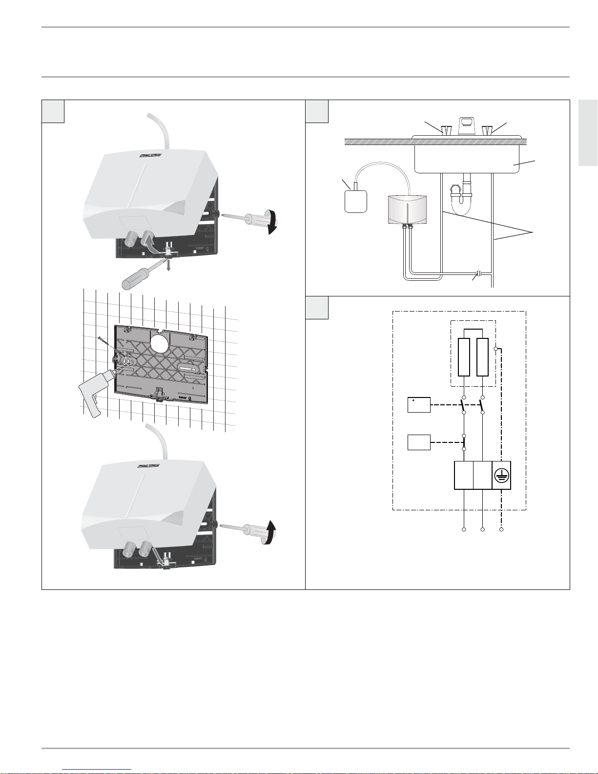
Figure C legend
5
Electrical junction box
6 Water supply line for faucet installation
7 Sink
8 Cold valve (right)
9 Hot valve (left)
10
Shut off valve
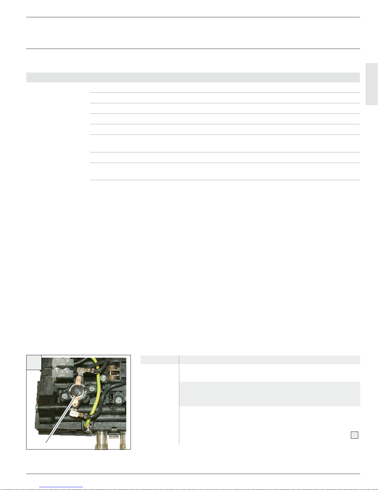
11
Reset button from safety pressure cut out
L N GRD
L L GRD Mini
WWW.STIEBEL-ELTRON-USA.COM MINI™ SERIES TANKLESS ELECTRIC WATER HEATERS | 5
OPERATION
OVERVIEW
THIS MANUAL MUST BE READ CAREFULLY BEFORE ATTEMPTING TO INSTALL THE MINI™ WATER HEATER. IF YOU DO NOT FOLLOW
THE SAFETY RULES OR THE INSTRUCTIONS OUTLINED IN THIS MANUAL, THE UNIT MAY NOT OPERATE PROPERLY AND IT COULD
CAUSE PROPERTY DAMAGE, SERIOUS BODILY INJURY AND/OR DEATH.
STIEBEL ELTRON, INC. WILL NOT BE LIABLE FOR ANY DAMAGES BECAUSE OF FAILURE TO COMPLY WITH THE INSTALLATION AND
OPERATING INSTRUCTIONS OUTLINED IN THIS MANUAL OR BECAUSE OF IMPROPER USE. IMPROPER USE INCLUDES THE USE OF THIS
APPLIANCE TO HEAT ANY LIQUID OTHER THAN WATER. FAILURE TO COMPLY WITH THE INSTALLATION AND OPERATING INSTRUCTIONS
OR IMPROPER USE VOIDS WARRANTY. NEVER REMOVE THE UNIT’S COVER UNLESS THE ELECTRICITY IS TURNED OFF.
IF YOU HAVE ANY QUESTIONS REGARDING THE INSTALLATION OR OPERATION OF THIS WAT ER HEATER, OR IF YOU NEED ANY ADDITIONAL
INSTALLATION MANUALS, PLEASE CALL OUR TECHNICAL SERVICE LINE ON 800-582-8423 (USA AND CANADA ONLY). IF YOU ARE CALLING
FROM OUTSIDE THE U.S. OR CANADA, PLEASE CALL USA 413-247-3380 AND WE WILL REFER YOU TO A QUALIFIED STIEBEL ELTRON
SERVICE REPRESENTATIVE IN YOUR AREA.
6. Overview
6.1 General Description
The Mini™ tankless water heater differs from conventional storage
type water heaters in several ways. It does not store hot water.
Instead, water is heated instantaneously as it fl ows through the
unit. The powerful heating elements are activated by a fl ow
switch as water is drawn from a hot water faucet connected to
the Mini™. Due to the absence of stand-by losses, the Mini™ offers
greater energy effi ciency than storage type water heaters. The
unit will continuously supply hot water as long as the faucet is
open.
The temperature of the hot water delivered by the Mini™ depends
on the wattage of the heating element, the temperature of the
incoming cold water, and the water fl ow rate through the unit.
In order for the Mini™ to operate properly, it must be carefully
matched to the application.
In case you have questions regarding the way you plan to use the
Mini™, please call our technical service line at 800-582-8423 (USA
and Canada). For service outside the U.S. and Canada, please call
us at USA 413-247-3380. You can also e-mail us at info@stiebeleltron-usa.com or fax us at 413-247-3369.
The Mini™ can be used for hand washing type applications in the
U.S. and Canada:
– Restroom sinks in commercial/industrial facilities and homes
– Kitchen areas in commercial /industrial facilities and homes
– Cabins
– Special uses in photo developing shops, laboratories etc.
6.2 Important information before supplying power
to unit
Air in the cold water pipe will destroy the bare-wire
heating system of the Mini™. If the water supply to the
Mini™ has been interrupted, for example due to the risk of frost
or work on the water pipe, the following steps must be carried
out before the unit is used again.
» 1. Turn off circuit breaker.
» 2. Open a hot water tap downstream of the unit for as long as
is necessary for the unit and the cold water pipe to be free of
air.
» 3. Turn on circuit breaker.
All information in these Instructions for Use and Installation
must be followed carefully. They provide important information
with regard to safety, operation, installation, and maintenance
of the device.
6.3 Hot water output at max rated voltage
Model Wattage Typical hot water output
Mini™ 2-1* 1.8 kW 0.32 GPM
Mini™ 2.5-1 2.4 kW 0.50 GPM
Mini™ 3-1 3.0 kW 0.50 GPM
Mini™ 3.5-1 3.5 kW 0.66 GPM
Mini™ 4-2 3.5 kW 0.66 GPM
Mini™ 6-2 5.7 kW 1.00 GPM
The Mini™ can also be used for whole apartments and
homes in warm climate zones such as the Caribbean region,
Central America and Mexico due to the higher ambient water
temperatures.
6 | MINI™ SERIES TANKLESS ELECTRIC WATER HEATERS WWW.STIEBEL-ELTRON-USA.COM
*Note: Mini™ 2-1 is internally restricted to 0.32 GPM (1.3 l/min)
INSTALLATION
INSTALLATION INSTRUCTIONS
6.4 Incorrect use
The following are not permitted and will void the factory warranty:
- Installation of the appliance where it is at risk
from frost
- Installation in rooms where the appliance is at risk from
explosions as a result of dust, gases or vapors
- Ignoring safety clearances and safety zones
- Incorrect power connection
- Operation of the appliance without water fl owing through the
unit, or with air in the lines (See section 8, “Initial start-up”,
pg. 8)
- Operation of the unit with the cover off
- Heating liquids other than potable water
6.5 First steps to be taken in the event of
malfunction
WARNING: ALWAYS SHUT OFF POWER AND WATER TO
THE UNIT PRIOR TO REMOVING THE FILTER SCREEN.
FAILURE TO DO SO MAY CAUSE SERIOUS BODILY INJURY OR
DEATH.
» Check the circuit breaker
» Check the fi lter screen for scale blockage or dirt accumulation.
See section 12, “Troubleshooting”, pg. 9.
6.6 Maintenance and care
MAINTENANCE WORK, SUCH AS CHECKING ELECTRICAL
!
SAFETY, MAY ONLY BE CARRIED OUT BY A QUALIFIED
INSTALLER.
7.1 Mounting the unit
UNIT MUST BE INSTALLED WITH THE PLUMBING
!
CONNECTIONS POINTING DOWNWARD OR UPWARD ONLY.
WARNING: DO NOT INSTALL UNIT WHERE IT WOULD
ROUTINELY BE SPLASHED WITH WATER. ELECTRIC SHOCK
OR DEATH MAY RESULT.
» 1. Install Mini
point, for example, directly underneath the sink or next to the
shower stall.
» 2. Install Mini
unit before freezing temperatures set in.
» 3. Leave a minimum of 5" of clearance on all sides for
servicing.
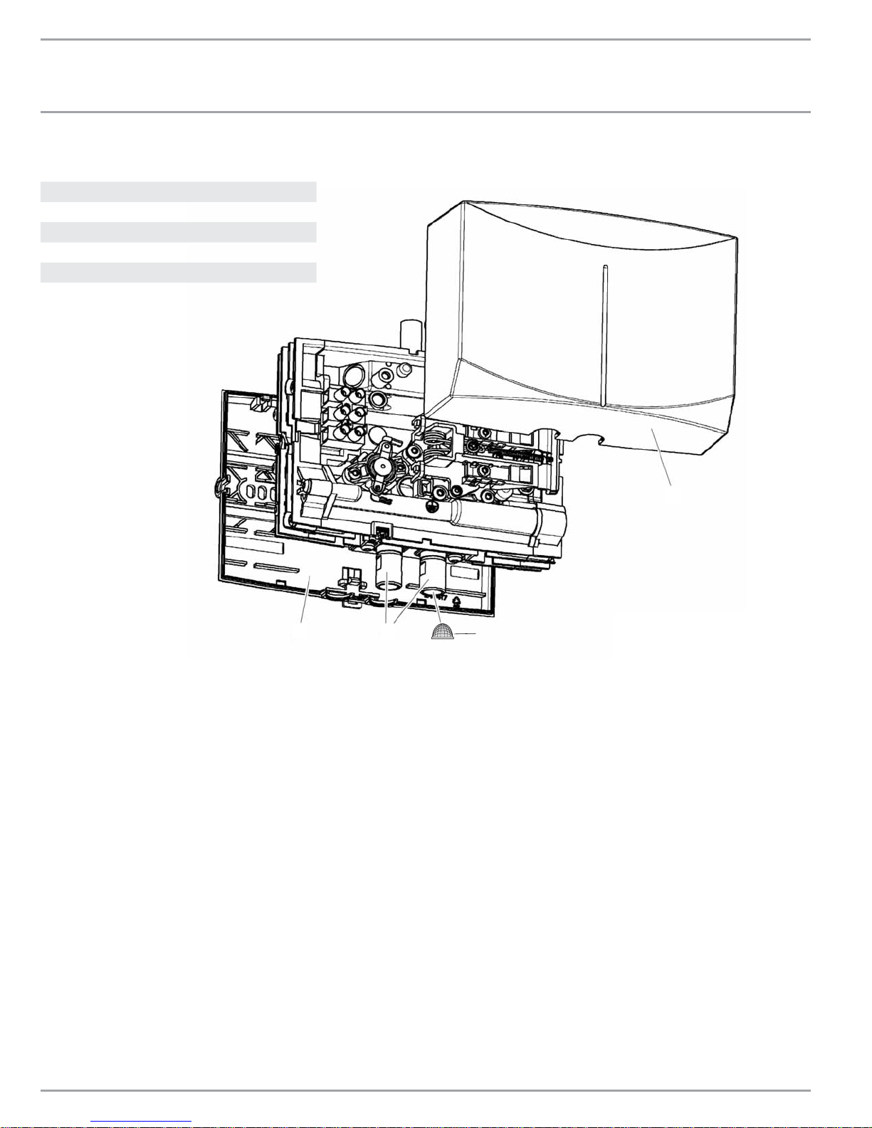
» 4. Remove plastic cover by removing screws located on the left
and right sides of the unit B.
» 5. Remove plastic backplate by pulling on the tab with a
screwdriver B.
» 6. Mount backplate securely to wall by putting two screws
through mounting holes
» 7. Snap unit back onto mounting plate
» 8. Reinstall cover with screws on left and right side of unit
™
as close as possible to the hot water draw-off
™
in a frost free area. If frost may occur, remove
.
A B
.
B
B
7.2 Plumbing connections
NOTE: IF SOLDERING NEAR THE UNIT IS NECESSARY, PLEASE
DIRECT THE FLAME AWAY FROM THE HOUSING OF THE UNIT
IN ORDER TO AVOID DAMAGE. EXCESSIVE HEAT FROM SOLDERING
ON COP PER PIPES NEAR THE MINI™ MAY CAUSE DAMAGE.
ALL PLUMBING WORK MUST COMPLY WITH NATIONAL AND
APPLICABLE STATE AND LOCAL PLUMBING CODES.
ENGLISH
.
WARNING: ALWAYS SHUT OFF POWER AND WATER TO
THE UNIT PRIOR TO REMOVING THE FILTER SCREEN.
FAILURE TO DO SO MAY CAUSE SERIOUS BODILY INJURY OR
DEATH.
Regularly clean and descale the fi lter screen located in the cold water
inlet connection and if necessary replace. Always shut off power and
water to the unit prior to removing the fi lter screen.
A damp cloth is suffi cient for cleaning of the unit's housing. Do not
use any abrasive or corrosive cleaning agents.
7. Installation instructions
KEEP THESE INSTRUCTIONS CAREFULLY AND PASS THEM
ON TO YOUR SUCCESSOR IN THE EVENT OF A CHANGE
IN OWNERSHIP, IN THE EVENT OF MAINTENANCE AND POSSIBLE
REPAIR WORK THEY SHOULD BE PASSED TO THE QUALIFIED
INSTALLER FOR HIS OR HER REFERENCE.
WWW.STIEBEL-ELTRON-USA.COM MINI™ SERIES TANKLESS ELECTRIC WATER HEATERS | 7
» 1. All plumbing work must comply with national and
applicable state and local plumbing codes.
» 2. A pressure reducing valve must be installed if the cold water
supply pressure exceeds 150 PSI (10 bar).
» 3. Make certain that the cold water supply line has been
fl ushed to remove any scale and dirt.
» 4. Install isolating valve in cold water line as shown in
illustration C. This allows the unit to be isolated for
maintenance purposes.
» 5. Cold water connection (inlet) is on the right side of the unit,
hot water connection (outlet) is on the left side of unit.
» 6. Tankless water heaters such as the Mini
to be equipped with a Pressure and Temperature Relief Valve
(except in Massachusetts). If the local inspector will not pass
the installation without a P+T valve, it should be installed on
the hot water outlet side of unit.
» 7. The Mini
steel hose with a 3/8˝ O.D. Tube Outlet.
» 8. When all plumbing work is completed, check for leaks and
take corrective action before proceeding.
™
is designed for connection to a braided stainless
™
are not required
INSTALLATION
elec
tr
o
n
ic
°C
INITIAL START-UP
7.3 Electrical connection
WARNING: BEFORE BEGINNING ANY WORK ON THE
ELECTRIC INSTALLATION, BE SURE THAT THE MAIN CIRCUIT
BREAKER PANEL SWITCH IS “OFF” TO AVOID ANY DANGER OF
ELECTRIC SHOCK. FAILURE TO DO SO MAY RESULT IN SERIOUS
INJURY OR DEATH. ALL MOUNTING AND PLUMBING MUST BE
COMPLETED BEFORE PROCEEDING WITH ELECTRICAL HOOK-UP.
WHERE REQUIRED BY LOCAL, STATE OR NATIONAL ELECTRICAL
CODES, THE CIRCUIT SHOULD BE EQUIPPED WITH A GROUND FAULT
INTERRUPTER.
WARNING: AS WITH ANY ELECTRIC APPLIANCE, FAILURE TO
ELECTRICALLY GROUND UNIT MAY RESULT IN SERIOUS INJURY OR
DEATH.
CAUTION: INSTALLING A MINI™ 2-1, MINI™ 2.5-1, MINI™ 3-1, OR
MINI™ 3.5-1 ON A 208 V OR 220–240 V CIRCUIT WILL DESTROY
THE HEATING ELEMENT. THIS IS CONSIDERED IMPROPER
INSTALLATION AND WILL VOID YOUR FACTORY WARRANTY.
Voltage
Mini™ 2-1: 110–120 V
Mini™ 2.5-1: 110–120 V
Mini™ 3-1: 110–120 V
Mini™ 3.5-1: 110–120 V
Mini™ 4-2: 220–240, 208 V
Mini™ 6-2: 220–240, 208 V
1. All elec trical work must comply with national and applicable s tate
and local electrical codes.
2. The Mini™ should be connected to a properly grounded dedicated
branch circuit of proper voltage rating. In installa tions with several
Mini™ units, each unit requires an independent circuit. Please refer to
the technical data table for the correct wire and circuit breaker size.
3. The open ends of the “pigtail” must be feed into an electrical
junction box. Then feed wires through strain relief clamp and tighten
clamp down on wire.
4. Reinstall plastic cover.
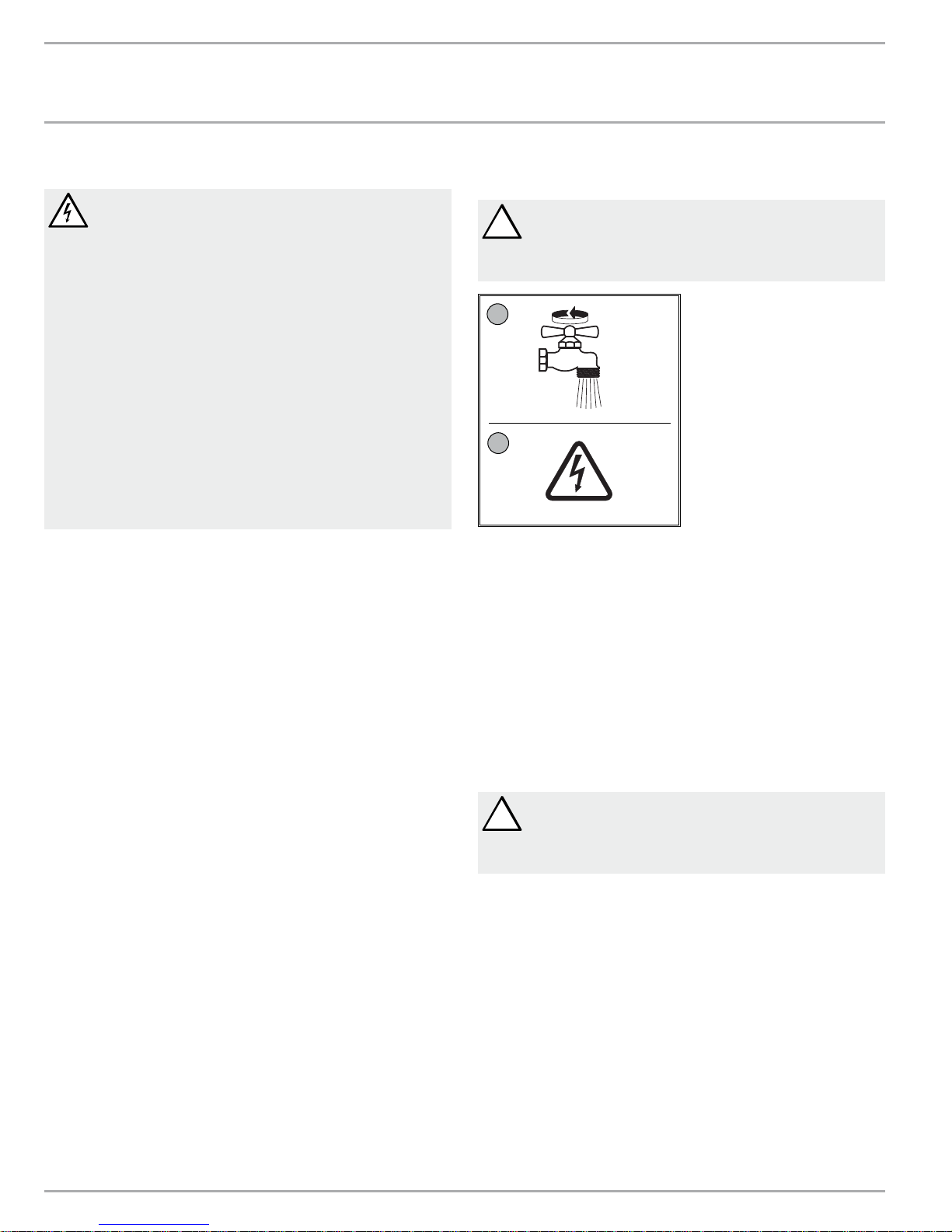
8. Initial start-up
WARNING: OPEN HOT WATER FAUCET FOR A FEW MINUTES
!
UNTIL WATER FLOW IS CONTINUOUS AND ALL AIR IS
PURGED FROM WATER PIPES. THE UNIT’S PLASTIC COVER MUST
BE INSTALLED BEFORE THE CIRCUIT BREAKER IS TURNED ON.
1
on
2
on
26_02_02_0436
9. Water heater hand over
Explain the functions of the unit to the user and familiarize him or
her with its use.
Important instructions:
» Draw the user’s attention to possible hazards (scalding).
» Hand over these instructions for future reference.
» In order to obtain a proper temperature at a single spout
mixer-type faucet, restrict cold water fl ow to faucet by partially
closing the cold water shut-off valve under the sink until cold
water and hot water fl ow rates are approximately the same.
10. Normal maintenance
CAUTION: OTHER THAN THE FILTER SCREEN, THE MINI™
!
DOES NOT CONTAIN ANY PARTS SERVICEABLE BY THE LAY
PERSON. IN CASE OF MALFUNCTION PLEASE CONTACT A LICENSED
PLUMBER OR ELECTRICIAN.
Stiebel Eltron Mini™ tankless heaters are designed for a very long
service life. Actual life expectancy will vary with water quality and
use. The unit itself does not require any regular maintenance.
However, to ensure consistent water fl ow, it is recommended to
periodically remove scale and dirt that may build up at the aerator
of the faucet or in the shower head. Also, the Mini™ has a built in
fi lter screen that should be cleaned from time to time. In order to
do this, turn off the cold water supply at the isolating valve. Clean
screen and put the screen back into its original position.
8 | MINI™ SERIES TANKLESS ELECTRIC WATER HEATERS WWW.STIEBEL-ELTRON-USA.COM
INSTALLATION
TECHNICAL DATA
11. Technical data
Mini™ 2-1 Mini™ 2.5-1 Mini™ 3-1 Mini™ 3.5-1 Mini™ 4-2 Mini™ 6-2
Item number 231045 232098 220816 232099 222039 220817
Phase 1 1 1 1 1 1
Voltage 110–120 V 110–120 V 110–120 V 110–120 V 220–240 V 208 V 220–240 V 208 V
Wattage 1.8 kW 2.4 kW 3.0 kW 3.5 kW 3.5 kW 2.6 kW 5.7 kW 4.3 kW
Max. amp, load 15 A 20 A 25 A 29 A 14.6 A 12.7 A 23.8 A 20.6 A
Required circuit
breaker size
Required wire size
Minimum water flow
to activate unit
Recommended inlet
temp. range 41–77 °F (5–25 °C)
Nominal water volume 0.026 gal (0.1 l)
Max. working pressure 150 psi (10 bar)
Tested to pressure 300 psi (20 bar)
Weight 3.44 lbs. (1.56 kg)
Height
Depth
Width
20 A 30 A 30 A 40 A 20 A 20 A 30 A 30 A
12 AWG 10 AWG 10 AWG 10 AWG 12 AWG 12 AWG 10 AWG 10 AWG
0.21 GPM
(0.8) l/min
6½˝ (165 mm)
3¼˝ (82 mm)
7½˝ (190 mm)
0.40 GPM
(1.5) l/min
0.40 GPM
(1.5) l/min
0.40 GPM
(1.5) l/min
0.40 GPM
(1.5) l/min
ENGLISH
0.77 GPM
(2.9) l/min
Water connections for 3/8˝ O.D. flex connector
Heating system Nichrome bare-wire
Mini™ 2-1 models are internally restricted to 0.32 gpm. Mini™ 2-1, 2.5-1, 3-1 ship with a 0.5 gpm pressure compensating fl ow reducer/aerator that should be installed.
Mini™ 3.5-1, 4-2 ship with a 0.66 gpm pressure compensating fl ow reducer/aerator that should be installed.
-Tankless water heaters are considered a non-continuous load
-Conductors should be sized to maintain a voltage drop of less than 3 % under load
-For use with cold water supply only
12. Troubleshooting
E
Symptom Possible cause Solution
No hot water
despite fully
opened hot
water faucet.
No electrical power. Check the circuit breaker and
check voltage at the wiring block.
The activation fl ow rate needed to
turn on the heating element has
not been reached.
Safety cut out tripped – turn circuit breakers off
Clean fi lter screen.
– open Hot Valve to release pres-
sure from the unit
– reset saftey pressure cut out
– turn circuit breakers on
E
WWW.STIEBEL-ELTRON-USA.COM MINI™ SERIES TANKLESS ELECTRIC WATER HEATERS | 9
INSTALLATION
SPARE PARTS
13. Spare parts
Spare Part (all Mini™ models) Item no.
1 Front cover 271010
2 Rear housing 271011
3 Filter screen 272884
4 Plumbing connections 272777
5 O-rings (not shown) 083043
1
2
4
3
10 | MINI™ SERIES TANKLESS ELECTRIC WATER HEATERS WWW.STIEBEL-ELTRON-USA.COM
 Loading...