

Page 1
BEDIENUNG UND INSTALLATION
OPER AT ION AND INSTALLAT ION
UTILISATION ET INSTALLATION
BEDIENING EN INSTALLAT IE
OBSLUHA A INSTALACE
Multifernb edienung für Inf rarot-Kurzwellen-Heizstrahler | Multi remote control for
short-wave infrared radiant heaters | Télécommande multifonc tions pour radiateurs
radiants à ondes courtes IR | Multia fstandsbediening voor korte golf infrarood
straalkachel | Multifunkční dálkový ovladač pro infračervené kr átkovlnné zářiče
» IA remote control
Page 2

Contents
Page
Device explanation ..........................................................3
Safety instructions/Exclusion of liability .......................4
General safety instructions ............................................5
Scope of supply/general information .............................6
Intended use ....................................................................6
Instructions for radio operation .....................................7
Mounting of the wall bracket ..........................................8
Explanation of functions .................................................9
Transmission control light, Select button ....................9
Bidirectional / Unidirectional radio system .................10
Status display ............................................................10
Programming the transmitter .......................................10
Programming the transmitter/channel ........................12
Programming additional transmitters/channels ...........13
Switching the radiant heater on/off ..............................14
Switching on the radiant heater..................................14
Switching on intermediate stages ...............................15
Deleting the transmitter ................................................16
Deleting individual channels / the complete transmitter .16
Technical data ...............................................................17
Changing the battery ....................................................17
Cleaning .........................................................................17
Disposal .........................................................................17
Overview of programming commands .........................18
Notes on repair ..............................................................19
Notes on troubleshooting .............................................19
- 20 -
Page 3
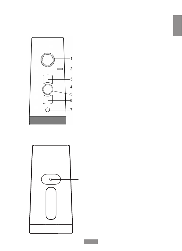
Device explanation
Front of the device
Back of the device
EN
Channel display
Operating mode display
UP button
STOP button
Status display
DOWN button
Select button
Programming button P
(under the cover)
- 21 -
Page 4
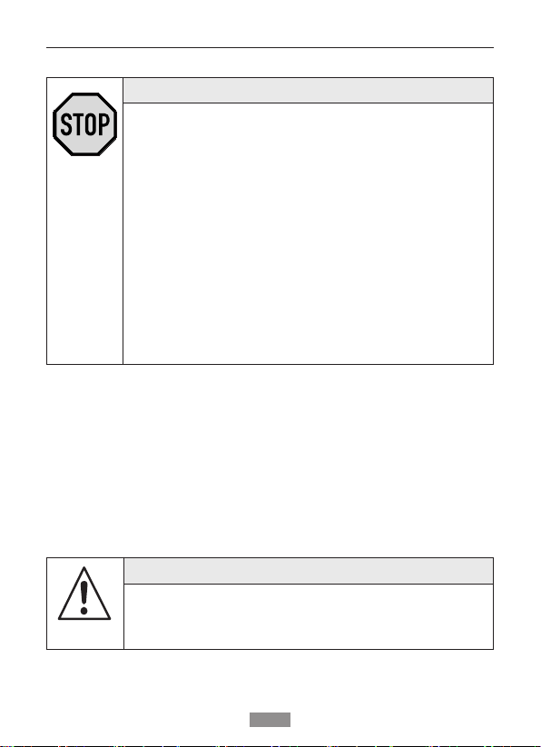
Safety instructions / Exclusion of liability
Observance of the operating instructions is the pre-
• Therefore, read the operating instructions before
• Ensure that the operating instructions are available
• The operator must ensure that the basic safety
• The operator must have completely read and
STOP!
requisite for disturbance-free operation and entitlement for claims related to defects.
you use the device!
to the user in legible form.
measures are observed and fulfilled.
understood the operating instructions.
Exclusion of liability:
It is essential to observe these operating instructions if the radiant
heater is to be used safely and if the various product characteristics
and performance features are to be achieved.
Stiebel Eltron GmbH & Co. KG assumes no liability for personal
injuries, property damages and financial losses that arise from nonobservance of the operating instructions.
Liability for material defects is excluded in such cases.
The short-wave infrared radiant heater can only be
CAUTION!
switched off completely by unplugging the mains plug
on the radiant heater.
- 22 -
Page 5

General safety instructions
Failure to observe them can lead to
CAUTION!
Observe the following safety instructions.
physical injuries!
General
• Never install or commission devices which are dam-
• Only use unmodified original parts.
• If the device is opened without permission or used in an
• The device contains small parts which can be swal
aged.
improper manner, or if it is incorrectly installed or oper
ated, there is a risk of damage to persons and property.
-
lowed.
Installation
• All installation work must be carried out by an electri-
• This electrician must possess the appropriate qualifica
• Observe any country-specific conditions when install
• The device may only be used by persons who have
cian.
tion.
ing the device.
read and understood the operating instructions.
-
Operation
• Use only in dry rooms.
• If one or more transmitters are used for controlling the
• Keep children away from the control units.
• Always replace batteries with an identical type (LR 06;
• Dispose of used batteries properly (collection point).
system, then the system must be visible during opera
tion.
AA).
-
-
-
- 23 -
Page 6

Scope of supply / General information / Intended use
Scope of supply
IA remote control (batteries contained in the device)
Wall bracket
2 wall plugs (Ø 6 mm)
2 screws (4 x 35)
Operating instructions
General information
The IA remote control has 5 channels, into which a number of
receivers can be programmed.
This device is characterised by simple operation, large control buttons and a Select button for channel selection.
The IA remote control is suitable for the operation of radiant heaters that are equipped with an IA receiver.
Intended use
The IA rmeote control is a hand-held radio transmitter. This may be
used exclusively for the control of radiant heaters that are equipped
with an IA receiver.
Other use, or use beyond this is not considered to be use for
intended purpose.
Stiebel Eltron GmbH & Co. KG is not liable for:
• Other use than described above
• Changes to the device
• Improper use
Please see the technical data contained in these operating
instructions.
- 24 -
Page 7

Instructions for radio operation
CAUTION!
Please observe the following safety instructions on radio operation.
Only use radio systems if they are allowed
and can be operated without interference.
• Please note that radio systems must not be operated
• The remote control is only approved for devices and
• The operator has no protection whatsoever from
• The range of the radio signal is limited by the govern
The short-wave infrared radiant heater is operated by
The short-wave infrared radiant heater can only be
in areas with an increased risk of interference
(e. g. hospitals, airports, ....).
systems for which any malfunction of the transmitter
or receiver would not result in a risk for persons, ani
mals or property, or if such a risk is covered by other
safety equipment.
interferences by other radio emitters and local ter
minals (e. g. also from radio installations, that are
normally used on the same frequency range).
ment and the built environment.
NOTE!
the IA remote control via the IA receiver.
switched off completely by unplugging the mains plug
on the radiant heater.
-
-
-
- 25 -
Page 8

Mounting of the wall bracket
Before installation in the required assembly position,
The bracket has to be fixed so that the drill hole does
NOTE!
check that the transmitter and receiver are functioning
properly.
not touch any electrical lines.
Mounting of the wall bracket
1. Fix the wall bracket so that the drill holes do not touch any
electrical lines!
2. Before mounting in the desired installation position, check that
transmitter and receiver are functioning properly.
3. Fix the bracket to the wall with the enclosed pins and screws.
The upper section of the wall bracket is moveable.
- 26 -
Page 9

Explanation of functions
Transmission control light
A radio signal is displayed by the lighting up of the transmission
control light.
The transmission control lamp flashes when transmitting if the battery power is reduced.
The transmitting power or the radio range will be reduced through
the reduction in the performance of the battery. If the transmission
control light no longer lights up when a button is pressed, the battery has to be replaced.
Select button
You can select up to 5 channels with the Select button. The individual channels are indicated through illumination of the relevant
LED on the status display.
- 27 -
Page 10

Explanation of functions: Radio system
Explanation of functions
Bidirectional radio system
A bidirectional radio system means the transmission of radio signals
to radio receivers and optional feedback from the radio receivers
to the transmitter. The radio signal can be sent directly to the target
receiver. If this is not possible, the radio signal is relayed via other
bidirectional nodes until it reaches the target receiver. The target
receiver executes the command and sends a conrmation back to the
transmitter. Bidirectional radio operation is only possible if all nodes
are bidirectional. Otherwise the system is only unidirectional.
Unidirectional radio system
A unidirectional radio system means the transmission of radio signals
to radio receivers. However, in contrast to the bidirectional radio
system, the radio receivers cannot send any conrmation back to the
transmitter. The transmission of radio signals from one radio receiver
to another is also not possible.
Status display
A radio signal is indicated by illumination of the status display - in
different colours, according to the radio principle.
The transmitting power or the radio range will be reduced through
the reduction in the performance of the battery. If the status display
no longer illuminates when the button is pressed, the batteries
must be replaced.
Note
Do not press the P button before the receivers are ready for
programming. During programming the channel selects a radio
system. If the receivers are not ready for programming, the
transmitter channel changes to unidirectional mode. In order
to return to the initial status, press the STOP and P buttons
simultaneously for 6 seconds, until the status display illuminates.
- 28 -
Page 11

Status display
The different colours of the status display have the following
meanings:
Status display Meaning
Flashing orange Channel (transmitter) not programmed in any
Orange
Quick ashing
Orange then green Channel (transmitter) operates bidirectionally
Orange then
ashing red
Red then green Channel (transmitter) operates bidirectionally
Red then ashing red Channel (transmitter) operates bidirectionally
Green with repetition,
then red (unidirec
tional)
Green Channel (transmitter) is operating unidrectionally:
Alternating orange
and green (or red),
then red
Flashing red Batteries weak
receiver
Channel (transmitter) in bidirectional program
ming mode. Operation of previously programmed
receivers not possible.
In group programming mode every 3 seconds
(even if button is not pressed)
and receiver has received the signal
Channel (transmitter) operates bidirectionally
and one of the receivers has not received the
signal
and receiver has received the signal, batteries
weak
and one of the receivers has not received the
signal, batteries weak
Channel (transmitter) has been deleted
-
Transmiiter signal is being sent
Channel (transmitter) is deleted
-
- 29 -
Page 12

Programming the transmitter/channel
Programming the transmitter/channel
The IA receiver must be installed.
1. Disconnect the fuse – and reconnect after a few seconds.
The receiver is now in programming mode for approx. 5 minutes.
2. Stand in front of the radiant heater with the IR remote control.
3. Press the Select
button to select a
channel.
PREREQUISITE!
!
4. Briefly press the
Programming button
P (on the back) .
5. Press the ▲ button
within the first 2 sec.
of the programming
phase during the 100
% heating cycle.
6. Press the ▼ button
within the first 2 sec.
of the programming
phase during the 50 %
heating cycle.
The transmitter is now programmed.
The radiant heater switches between 100 % and
50 % of its heating power
for 2 minutes.
Heating switches off for
a short time.
Heating switches off.
- 30 -
Page 13

Programming additional transmitters / channels
Programming additional transmitters / channels
If several receivers are connected to the same feed
You can stop the flashing if you briefly push the STOP
The channel assignment/change can now be made with-
To program additional transmitters in one receiver, please proceed as follows:
1.
Press the following buttons
on the programmed trans
mitter simultaneously:
▲ button
▼ button
Programming button P (on
the back).
Press the ▲ button within the
2.
first 2 sec. of the program
ming phase during the 100 %
heating cycle.
(New transmitter/channel)
NOTE!
line, then all are simultaneously ready to program.
Max. 16 transmitters can be programmed into a
receiver (IA receiver). The radiant heater begins to
briefly light up ‘at random’.
Individual channels/transmitters can now be assigned
to the respective receiver.
button of a transmitter which has already been programmed.
out you having to disconnect the individual receivers.
Press the buttons
-
-
for approx. 3 sec
onds. The heating
system alternates
between 100% and
50% heating power
for 2 minutes.
Heating switches
off for a short time.
-
3.
Press the ▼ button within the
first 2 sec. of the programming
phase during the 50 % heating
cycle.
(New transmitter/channel)
The transmitter is now programmed.
- 31 -
Heating
switches off.
Page 14

Switching the radiant heater on/off
Switching the radiant heater on/off
The transmitter is now programmed.
Switching the heating system on.
Press the ▲ or ▼ button.
Switching the heating system off.
Press the STOP button.
The short-wave infrared radiant heater can only be
The IA receiver automatically switches the connected
PREREQUISITE!
!
NOTE!
switched off completely by unplugging the mains plug
on the radiant heater.
NOTE!
radiant heater(s) off after 12 hours.
- 32 -
Page 15

Switching on intermediate stages
Switching on intermediate stages
The transmitter is now programmed.
1. Briefly press the ▲ button twice in succession.
The radiant heater heats with approx. 66
2. Briefly press the ▼ button twice in succession.
The radiant heater heats with approx. 50
PREREQUISITE!
!
% of its rated power.
% of its rated power.
- 33 -
Page 16

Deleting transmitter/channels / Technical data
Deleting individual channels
1. Press simultaneously:
• Programming button P (on the back)
• STOP button
2. Hold down this button combination for approx. 6 seconds,
until the LED goes out briefly 3x.
Deleting the complete transmitter
1. Press simultaneously:
• Programming button P (on the back)
• ▲ button
• STOP button
• ▼ button
2. Hold down this button combination for approx. 6 seconds,
until the LED goes out briefly 3x.
Technical data
Operating voltage 3 V DC
Battery type 2 x LR 06 (AA)
IP Code IP 20
Permitted ambient temperature 10 to +55 °C
Radio frequency 868.3 MHz
Notification number CE 0682
Dimensions in mm (remote control) L 120 x W 51 x H 26
Dimensions in mm (wall bracket) L 70 x W 26 x H 26
- 34 -
Page 17

Changing the battery / Cleaning / Disposal
Changing the battery
• Always replace batteries with an identical type
• Dispose of used batteries properly (collection point).
1. Unscrew the device at the bottom and open the
housing.
2. Remove the batteries.
3. Insert the new batteries (LR 06; AA) in the
correct position in the transmitter.
4. Reassemble the device.
NOTE!
(2 x LR 06; AA).
Cleaning
Clean the device with a damp cloth only.
Do not use cleaning agents, these can attack the plastic.
Disposal
Please observe the current national regulations.
Dispose of according to the condition and existing regulations.
E.g. as:
• Electronic waste (PCB)
• Plastic (housing parts)
• Batteries
- 35 -
Page 18

Overview of programming commands
The IA receiver is in program-
ming mode and the radiant
heater switches repeatedly to
100 % and 50 % of its heating
Prerequisite
Prior interruption of the mains
voltage (time frame 5 min.)
Transmitter is already pro-
grammed
Transmitter is already pro-
Tap
Press for approx. 3 sec. until LED
goes out briey
Tap
grammed
power
Briey press the 'UP' button im-
mediately (within 2 sec.) after the
radiant heater lights up with 100 %
heating power and briey press
the 'DOWN' button after the radiant
heater lights up with 50 % heating
power.
Transmitter is already pro-
grammed
Transmitter is already pro-
grammed
Acknowledgement takes place by
switching the radiant heater off.
Press for approx. 6 sec., until the
LED goes off briey
Press for approx. 6 sec., until the
LED goes off briey 3x and then
completely
●P
Function Key combination Procedure Condition/
Starting programming
▲ + ▼ + ●P
●
mode
(programming time: 2
min.)
Stopping programming
mode
heating power
▲ at 100 %
Programming the
transmitter
(IA remote control)
- 36 -
heating power
▼ at 50 %
●P + ●
▲ + ● + ▼ + ●P
Deleting individual
channels
Deleting the complete
transmitter
Page 19

Notes on repair / Notes on troubleshooting
Notes on repair
Please contact us if you are unable to eliminate a problem.
When contacting our service team, please always state the item
description and number from the type plate (back of device).
– Article number – Attendant circumstances
– Article designation – Own assumption
– Type of fault – Previously occurring unusual
events
Notes on troubleshooting
Fault Cause Remedy
No radio reception.
Transmitter is not
programmed.
Program the transmitter.
Heater does
not heat or
only heats with
reduced power.
1. Radiant heater
wrongly connected.
2. Heating element is
defective.
3. Overtemperature
warning, overtemperature cutout
or emergency cutout active on the
receiver side.
- 37 -
1. Check
connection
(→ Radiant Heater
Instructions).
2. Replace heating
element
(→ Radiant Heater
Instructions).
3. Ensure cooling, in
case of emergency
shutdown also
switch off the supply voltage.
Page 20

Deutschland
STIEBEL ELTRON GmbH & Co. KG
Dr.-Stiebel-Straße 33 | 37603 Holzminden
Tel. 05531 702-0 | Fax 05531 702-480
info@stiebel-eltron.de
www.stiebel-eltron.de
Verkauf Tel. 05531 702-110 | Fax 05531 702-95108 | info-center@stiebel-eltron.de
Kundendienst Tel. 05531 702-111 | Fax 05531 702-95890 | kundendienst@stiebel-eltron.de
Ersatzteilverkauf Tel. 05531 70 2-120 | Fax 05531 702-95335 | ersatzteile@stiebel-eltron.de
Irrtum und technische Änderungen vorbehalten! | Subject to errors and technical changes! | Sous réserve
d‘erreurs et de modifications techniques! | Onder voorbehoud van ver
g
issingen en technische wijzigingen! |
Salvo error o modificación técnica! | Excepto erro ou alteração técnica | Zastrzeżone zmian
y
techniczne i
ewentualne błędy | Omyly a technické změny jsou vyhrazeny! | A muszaki változtatások és tévedések
jog
át
fenntartjuk! |
Отсутствие ошибок не гарантируется. Возможны технические изменения.
| Ch
yby
a
technické zmeny sú vyhradené! Stand 9046
Australia
STIEBEL ELTRON Australia Pty. Ltd.
6 Prohasky Street | Port Melbourne VIC 3207
Tel. 03 9645-1833 | Fax 03 9645-4366
info@stiebel.com.au
www.stiebel.com.au
Austria
STIEBEL ELTRON Ges.m.b.H.
Eferdinger Str. 73 | 4600 Wels
Tel. 07242 47367-0 | Fax 07242 47367-42
info@stiebel-eltron.at
www.stiebel-eltron.at
Belgium
STIEBEL ELTRON bvba/sprl
't Hofveld 6 - D1 | 1702 Groot-Bijgaarden
Tel. 02 42322-22 | Fax 02 42322-12
info@stiebel-eltron.be
www.stiebel-eltron.be
China
STIEBEL ELTRON (Guangzhou) Electric
Appliance Co., Ltd.
Rm 102, F1, Yingbin-Yihao Mansion, No. 1
Yingbin Road
Panyu District | 511431 Guangzhou
Tel. 020 39162209 | Fax 020 39162203
info@stiebeleltron.cn
www.stiebeleltron.cn
Czech Republic
STIEBEL ELTRON spol. s r.o.
K Hájům 946 | 155 00 Praha 5 - Stodůlky
Tel. 251116-111 | Fax 235512-122
info@stiebel-eltron.cz
www.stiebel-eltron.cz
Finland
STIEBEL ELTRON OY
Kapinakuja 1 | 04600 Mäntsälä
Tel. 020 720-9988
info@stiebel-eltron.fi
www.stiebel-eltron.fi
France
STIEBEL ELTRON SAS
7-9, rue des Selliers
B.P 85107 | 57073 Metz-Cédex 3
Tel. 0387 7438-88 | Fax 0387 7468-26
info@stiebel-eltron.fr
www.stiebel-eltron.fr
Hungary
STIEBEL ELTRON Kft.
Gyár u. 2 | 2040 Budaörs
Tel. 01 250-6055 | Fax 01 368-8097
info@stiebel-eltron.hu
www.stiebel-eltron.hu
Japan
NIHON STIEBEL Co. Ltd.
Kowa Kawasaki Nishiguchi Building 8F
66-2 Horikawa-Cho
Saiwai-Ku | 212-0013 Kawasaki
Tel. 044 540-3200 | Fax 044 540-3210
info@nihonstiebel.co.jp
www.nihonstiebel.co.jp
Netherlands
STIEBEL ELTRON Nederland B.V.
Daviottenweg 36 | 5222 BH 's-Hertogenbosch
Tel. 073 623-0000 | Fax 073 623-1141
info@stiebel-eltron.nl
www.stiebel-eltron.nl
Poland
STIEBEL ELTRON Polska Sp. z O.O.
ul. Działkowa 2 | 02-234 Warszawa
Tel. 022 60920-30 | Fax 022 60920-29
biuro@stiebel-eltron.pl
www.stiebel-eltron.pl
Russia
STIEBEL ELTRON LLC RUSSIA
Urzhumskaya street 4,
building 2 | 129343 Moscow
Tel. 0495 7753889 | Fax 0495 7753887
info@stiebel-eltron.ru
www.stiebel-eltron.ru
Slovakia
TATRAMAT - ohrievače vody s.r.o.
Hlavná 1 | 058 01 Poprad
Tel. 052 7127-125 | Fax 052 7127-148
info@stiebel-eltron.sk
www.stiebel-eltron.sk
Switzerland
STIEBEL ELTRON AG
Industrie West
Gass 8 | 5242 Lupfig
Tel. 056 4640-500 | Fax 056 4640-501
info@stiebel-eltron.ch
www.stiebel-eltron.ch
Thailand
STIEBEL ELTRON Asia Ltd.
469 Moo 2 Tambol Klong-Jik
Amphur Bangpa-In | 13160 Ayutthaya
Tel. 035 220088 | Fax 035 221188
info@stiebeleltronasia.com
www.stiebeleltronasia.com
United Kingdom and Ireland
STIEBEL ELTRON UK Ltd.
Unit 12 Stadium Court
Stadium Road | CH62 3RP Bromborough
Tel. 0151 346-2300 | Fax 0151 334-2913
info@stiebel-eltron.co.uk
www.stiebel-eltron.co.uk
United States of America
STIEBEL ELTRON, Inc.
17 West Street | 01088 West Hatfield MA
Tel. 0413 247-3380 | Fax 0413 247-3369
info@stiebel-eltron-usa.com
www.stiebel-eltron-usa.com
A 319416-38849-9053
C 18 122.5301
4<AMHCMO=bjebgd>
18 122.5301
 Loading...