

STIEBEL ELTRON CNS 75-2 E, CNS 150-1 E, CNS 200-2 E, CNS 150-2 E, CNS 240-2 E Operation And Installation
...Page 1
OPERATION AND INSTALLATION
GUÍA DE OPERACIÓN E INSTALACIÓN
MODE D’EMPLOI ET MANUEL D’INSTALLATION
WALL MOUNTED CONVECTION HEATER
CONVECTOR DE PARED
APPAREIL DE CHAUFFAGE À CONVECTION MURAL
» CNS 50-2 E
» CNS 75-2 E
» CNS 100-1 E
» CNS 100-2 E
» CNS 150-1 E
» CNS 150-2 E
» CNS 200-2 E
» CNS 240-2 E
» CNS 150-2 24H
» CNS 200-2 24H
» CNS 240 -2 24H
STIEBEL ELTRON, Inc.
17 West Street | West Hatfield, MA 01088
Tel. 413-247-3380 | Fax 413-247-3369
Email info
@
stiebel-eltron-usa.com
www.stiebel-eltron-usa.com
Page 2

2 |CNS E / CNS 24H WWW.STIEBEL-ELTRON-USA.COM
CONTENTS | OPERATION
IMPORTANT INSTRUCTIONS
OPE RA TION
1. IMPORTANT INSTRUCTIONS
SAVE THESE INSTRUCTIONS
When using electrical appliances, basic precautions should always
be followed to reduce the risk of fire, electric shock, and injury to
persons, including the following:
1. Read all instructions before installing or using this heater.
2. This heater is hot when in use. To avoid burns, do not let bare
skin touch hot surfaces. Keep combustible materials, such as
furniture, pillows, bedding, papers, clothes, etc. and curtains at
least 3 feet (1 m) from the front of the heater and keep them at
least 3 feet (1 m) away from the sides and rear.
3. Extreme caution is necessary when any heater is used by or
near children or invalids and whenever the heater is left operating
and unattended.
4. Do not operate any heater after it malfunctions. Disconnect
power at service panel and have heater inspected by a reputable
electrician before reusing.
1.1 Document information
The chapter Operation is intended for users and heating
contractors.
The chapter Installation is intended for heating contractors.
Read these instructions carefully before using the
appliance and retain them for future reference. Pass
on the instructions to any new users.
1.2 Key to symbols
1.2.1 Layout of safety information
Safety information comprises a warning symbol, a keyword and
a text giving information. Safety information is printed on a grey
background.
Example:
DANGER: Electrocution
Install the appliance in such a way that control
equipment...
12 3
4
1 Symbol (see chapter on warning symbols/symbols)
2 Keyword (see chapter on keywords)
3 Description (see chapter on warning symbols/symbols)
4 Information text
OPERATION
1. Important Instructions _________________________________________2
1.1 Document information ____________________________________________ 2
1.2 Key to symbols ______________________________________________________ 2
2. Safety ____________________________________________________________3
2.1 Intended use _________________________________________________________ 3
2.2 Safety information _________________________________________________ 3
2.3 ETL / UL designation _______________________________________________ 4
2.4 Type label ____________________________________________________________ 4
3. Register your product __________________________________________4
4. Appliance description __________________________________________4
5. CNS E Operation ________________________________________________4
5.1 Description of the user interface ________________________________ 4
5.2 Frost protection _____________________________________________________ 4
5.3 Limiting the temperature controller ____________________________ 5
5.4 Shutting down ______________________________________________________ 5
6. CNS 24H Operation _____________________________________________5
6.1 Operating modes ___________________________________________________ 5
6.2 Timer switch _________________________________________________________ 5
6.3 Temperature selector ______________________________________________ 6
6.4 Frost protection _____________________________________________________ 6
6.5 Limiting the temperature controller ____________________________ 6
6.6 Shutting down ______________________________________________________ 6
7. Cleaning, care and maintenance ______________________________6
8. What to do if ... _________________________________________________6
INSTALLATION
9. Safety ____________________________________________________________7
9.1 General safety instructions _______________________________________ 7
9.2 Instructions, standards and regulations _______________________ 7
10. Appliance description __________________________________________7
10.1 Standard delivery ___________________________________________________ 7
11. Installation ______________________________________________________7
11.1 Installing the wall mounting bracket ___________________________ 7
11.2 Appliance installation _____________________________________________ 7
11.3 Dismounting the appliance _______________________________________ 8
11.4 Power supply ________________________________________________________ 8
11.5 Terminal block ______________________________________________________ 8
12. Troubleshooting_________________________________________________8
13. Appliance handover ____________________________________________8
14. Specifications ___________________________________________________9
14.1 Dimensions __________________________________________________________ 9
14.2 Minimum clearances to hard surfaces _________________________ 9
14.3 Specifications _______________________________________________________ 10
14.4 Wiring Diagram ____________________________________________________11
15. Warranty _______________________________________________________ 12
Page 3
OPERATION
SAFETY
WWW.STIEBEL-ELTRON-USA.COM CNS E / CNS 24H| 3
ENGLISH
1.2.2 Keywords
KEYWORD Description
DANGER The keyword DANGER indicates information which must be
observed, otherwise serious injury or death will result.
WARNING The keyword WARNING indicates information that must be
observed, otherwise serious injury or death may result.
CAUTION
The keyword CAUTION indicates information that must be
observed, otherwise relatively serious or light injuries may
result.
1.2.3 Warning symbols/symbols
Warning symbol
Description
Injury
Electrocution
Burns or scalding
!
Other situations
Fire
Never cover the appliance
Appliance disposal
1.2.4 Text symbols and layout in this documentation
Read the text next to this symbol carefully.
» The "»" symbol indicates that you should do something. The
action you need to take is described step by step.
— Passages with the "
–" symbol show you lists of items.
1.2.5 Information on the appliance
Never cover the appliance
1.2.6 Units of measurement
The dimensions in this document are given in in
/ mm. Any alternative units of measurements are
specified accordingly.
2. Safety
2.1 Intended use
This appliance is designed to heat living areas.
Any other use beyond that described shall be deemed inappropriate.
Observation of these instructions is also part of the correct use of
this appliance. Any modifications or conversions to the appliance
void all warranty rights.
2.2 Safety information
Operate the appliance only when fully installed and with all safety
equipment fitted.
The heater must be properly installed before it is used.
DANGER: Electrocution
Before cleaning, make sure the power has been
turned off at the circuit breaker panel and that the
heating element of the heater is cool.
WARNING: Fire
Never operate this appliance ...
...in rooms where the appliance is at risk of fire or
explosion as a result of chemicals, dust, gases or
vapours.
...in the direct proximity of pipes or receptacles that
carry or contain flammable or explosive materials.
...if work such as laying cables, grinding or sealing
is carried out in the installation room.
...if sprays, floor polish or similar products
containing napsan are used. Vent the room
sufficiently before heating.
...if the minimum clearances to adjacent object
surfaces are not maintained, for example to
furniture, net curtains, curtains, textiles or other
flammable materials (see 14.2, “Minimum clearances
to hard surfaces”, pg. 9).
...if an appliance component is damaged, the
appliance has fallen over or already had a fault.
WARNING: Injury
Where children or persons with limited physical,
sensory or mental capabilities are allowed to control
this appliance, ensure that this will only happen
under supervision or after appropriate instructions
by a person responsible for their safety.
Children must be supervised to ensure that they
never play with the appliance.
WARNING: Fire
Never place any flammable, combustible or
insulating objects or materials, such as laundry,
blankets, magazines, containers with floor polish or
napsan, spray cans or similar on the appliance or in
direct proximity to it.
WARNING Burns
The surfaces of the appliance casing and the
expelled air become hot during operation (more than
176 °F / 80 °C).
CAUTION: Overheating
Never cover the appliance
Never step on the appliance.
Page 4
OPERATION
REGISTER YOUR PRODUCT
4 |CNS E / CNS 24H WWW.STIEBEL-ELTRON-USA.COM
2.3 ETL / UL designation
The ETL / UL designation shows that the appliance meets all
essential requirements according to UL standard 499.
2.4 Type label
The type label is located on the right on the exterior of the
appliance.
3. Register your product
You must register this product within 90 days of
purchase on our web site in order to activate the
standard warranty or to be eligible for the extended
warranty. Go to our web site at
www.stiebel-eltron-usa.com and click on register
your product.
Before beginning the registration process, we suggest that you
gather the necessary information which will be as follows:
Type, Example: CNS 50-2 E (from the white label that is on the
right side of the unit)
Number listed after “Nr.”
Place of Purchase
Purchase Date
First & Last Name
Email address
Physical Address
Phone Number
IF YOU HAVE ANY QUESTIONS CONCERNING THE REGISTRATION PROCESS OR WARRANTY OPTIONS, PLEASE CONTACT
STIEBEL ELTRON USA DIRECTLY AT (800)-582-8423.
4. Appliance description
The appliance is an electric direct heater only for installation on
a wall.
The appliance is suitable as a full heating system in bathrooms,
for example, or for use between seasons and as a booster heater
in smaller rooms, such as hobby and guest rooms.
The air in the appliance is heated by a heating element and
expelled via natural convection through the air outlet grille at the
top. Cool room air flows in through the apertures at the bottom
of the appliance.
After mounting the appliance on the wall and making the
electrical connection to the main breaker, the appliance is ready
for operation.
5. CNS E Operation
The CNS E is a convection operated space heater with a thermostat
and an on/off switch.
5.1 Description of the user interface
» Switch the appliance ON via the switch on the right hand side
of the appliance.
» Set the required room temperature via the continuously variable
temperature selector (for temperatures see specification
chapter).
26_07_31_0037
As soon as the selected room temperature is reached, it is
constantly maintained at this selected temperature through
periodic heating (the output of the appliance must correspond at
least to the required heat demand of the room).
If several appliances are installed in a single room, the setting
at the temperature selector on each appliance can be different.
To avoid excessive power consumption when windows are open,
you should stop the appliance while venting.
5.2 Frost protection
To disable normal heating but maintain protection against
freezing, turn the temperature selector as far to the right as
possible. In this position, the temperature controller switches
on the heating element automatically if the room temperature
drops below the frost protection temperature (47 °F / 7 °C).
Page 5
OPERATION
CNS 24H OPERATION
WWW.STIEBEL-ELTRON-USA.COM CNS E / CNS 24H| 5
ENGLISH
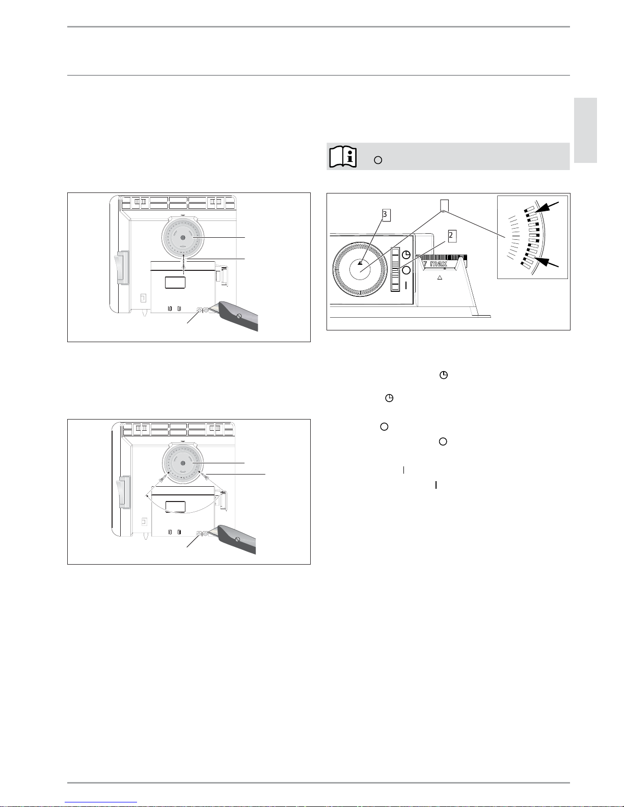
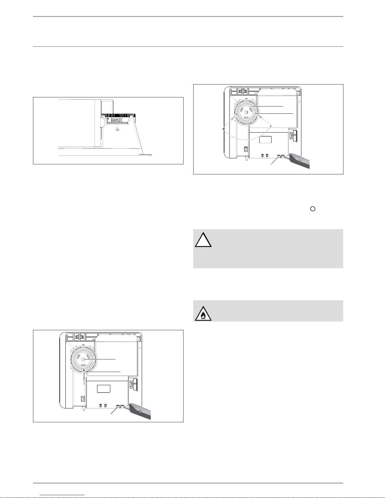
5.3 Limiting the temperature controller
Using the two pins fitted to the back of the control casing, you
can fix the temperature controller at a certain setting or limit the
temperature setting range.
» Break out the pins.
» To prevent adjustment of the selected temperature, push a pin
into the hole opposite (see diagram).
1
1
2
26_07_31_0038
1 Pin
2 Temperature selector
» To limit the temperature setting range, set the minimum and
maximum values at the temperature selector, and push a pin for
each into the slightly offset hole opposite (see diagram).
26_07_31_0171
1
1
2
1 Pin
2 Temperature selector
5.4 Shutting down
» Move the switch on the right of the appliance to OFF.
6. CNS 24H Operation
The CNS 24H is a convection space heater with a 24-hour timer,
thermostat and an on/off switch.
To switch the appliance off, move the ON/OFF switch
to
6.1 Operating modes
12
13
14
2
1
3
3
2
1 Timer switch
2 ON/OFF switch
3 Arrow marking the time
Heating with the time switch
» To set the appliance into the timer mode, move the ON/OFF
switch to the
symbol. The appliance turns on in accordance
to the timer settings (see 6.2, “Timer switch”, pg. 5).
Appliance off
» Move the ON/OFF switch to to turn the appliance off. In this
mode, frost protection is disabled.
Constant operation
» Move the ON/OFF switch to to keep the appliance in continuous
operation. The appliance will operate until the set temperature
is reached. Frost protection is enabled in this mode.
6.2 Timer switch
In the timer and constant operation modes, the appliance heats
to the set temperature on the temperature selector.
When in timer mode, the appliance will only activate during the
desired time, in addition to the set temperature.
» Set the time by turning the timer switch clockwise until the black
arrow points to the current time.
» Push the tabs on the edge of the time switch outwards for the
time that the appliance should heat. Every tab corresponds to
an ON or OFF period of 20 minutes.
Heating ON: Push the tabs outwards.
Heating OFF: Push the tabs inwards.
Page 6
6 |CNS E / CNS 24H WWW.STIEBEL-ELTRON-USA.COM
INSTALLATION
CLEANING, CARE AND MAINTENANCE
6.3 Temperature selector
» Set the required room temperature via the continuously variable
temperature selector (for temperatures see specification
chapter).
26_07_31_0037
As soon as the selected room temperature is reached, it is
constantly maintained at this selected temperature through
periodic heating (the output of the appliance must correspond at
least to the required heat demand of the room).
If several appliances are installed in a single room, the setting
at the temperature selector on each appliance can be different.
To avoid excessive power consumption when windows are open,
you should stop the appliance during this period.
6.4 Frost protection
» Turn the temperature selector as far to the right as possible. In
this position, the temperature controller switches on the heating
element automatically if the room temperature drops below the
frost protection temperature (47 °F / 7 °C).
6.5 Limiting the temperature controller
Using the two pins fitted to the back of the control casing, you
can fix the temperature controller at a certain setting or limit the
temperature setting range.
» Break out the pins.
» To prevent adjustment of the selected temperature, push a pin
into the hole opposite (see diagram).
1
1
2
26_07_31_0038
1 Pin
2 Temperature selector
» To limit the temperature setting range, set the minimum and
maximum values at the temperature selector, and push a pin for
each into the slightly offset hole opposite (see diagram).
26_07_31_0171
1
1
2
1 Pin
2 Temperature selector
6.6 Shutting down
» Move the switch on the right of the appliance to .
7. Cleaning, care and maintenance
!
WARNING:
Before cleaning, make sure the power has been
turned off at the circuit breaker panel and that the
heating element of the heater is cool. Failure to do
so could result in serious burns, electrocution,
serious bodily injury, or death.
If a pale brownish discolouration appears on the appliance casing,
wipe this off as soon as possible with a damp cloth. Clean the
appliance when cold with ordinary cleaning products. Avoid
abrasive or corrosive cleaning products.
CAUTION: Fire
Never spray cleaning spray into the air slot. Ensure
that no moisture can enter the appliance.
As part of regular maintenance, we recommend also having the
control components checked. The safety and control components
should be checked by a contractor no more than ten years after
commissioning.
8. What to do if ...
... the appliance does not heat up:
Check the temperature set at the appliance and the circuit breaker
box.
The appliance has a safety temperature controller that shuts
the appliance down if it overheats. After the cause has been
removed (for example air outlet or inlet apertures covered) and
the appliance has cooled down for a few minutes, operation starts
again.
If you cannot remedy the fault, contact your contractor. To facilitate
and speed up your enquiry, please provide the number on the type
plate (000000-0000-000000).
Page 7
WWW.STIEBEL-ELTRON-USA.COM CNS E / CNS 24H| 7
ENGLISH
INSTALLATION
SAFETY
INSTALLATION
9. Safety
Only qualified contractors should carry out installation,
commissioning, maintenance and repair of the appliance.
9.1 General safety instructions
We guarantee trouble-free function and operational reliability
only if the original accessories and spare parts intended for the
appliance are used.
DANGER: Electrocution
If you mount the appliance on the wall, do so in such
a way that control equipment cannot be touched by
a person in the bath or shower.
!
CAUTION:
-Only fit the wall mounted appliance to a vertical
wall that is temperature-resistant to at least 185 °F
/ 85 °C.
-Observe the minimum clearances to adjacent object
surfaces (for minimum clearances see specification
chapter).
-Never install the appliance directly below a wall
socket.
-Ensure that the power cable is not in contact with
any appliance components.
9.2 Instructions, standards and regulations
Observe all applicable national and regional
regulations and instructions.
Observe the Building and Garage Regulations [or
local regulations].
10. Appliance description
10.1 Standard delivery
» Wall mounting bracket (hooked into the appliance)
11. Installation
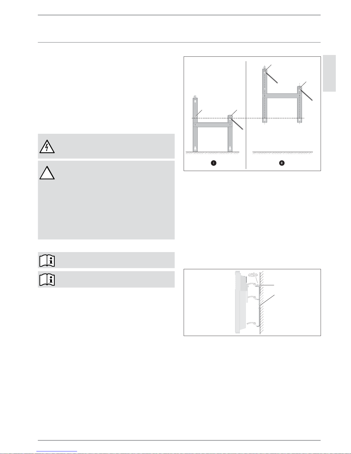
11.1 Installing the wall mounting bracket
You can use the wall mounting bracket as a template for wall
mounting; this ensures the required floor clearance.
» Unhook the wall mounting bracket.
» Place the centred wall mounting bracket level on the ground
and mark holes 1 and 2.
» Lift up the wall mounting bracket so that its lower holes match
up with the markings you have just made on the installation
wall.
» Mark holes 3 and 4 on the installation wall.
aaa
26_07_31_0124
1
3
2
4
» Drill holes at all four markings. Secure the wall mounting bracket
with suitable materials (screws, rawl plugs) depending on the
type of wall. With the vertical slots, you can compensate for an
offset fixing hole.
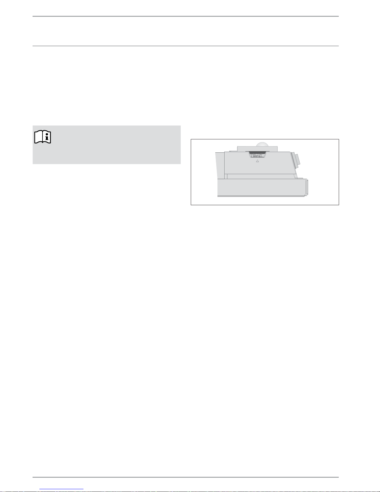
11.2 Appliance installation
» Hook the appliance by its slots in the back of the appliance on
to all four tabs of the wall mounting bracket simultaneously.
» Push the appliance to latch it in position.
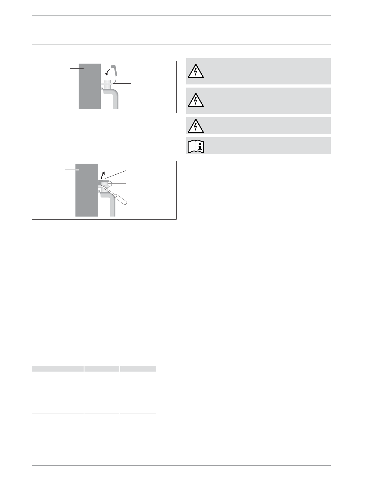
» Turn the locking bolt in the wall mounting bracket fully clockwise;
this locks the appliance in place.
» Push the safety cap onto the locking bolt to prevent it from
loosening.
26_07_31_0035
1
2
1 Locking bolt
2 Wall mounting bracket
Page 8
8 |CNS E / CNS 24H WWW.STIEBEL-ELTRON-USA.COM
INSTALLATION
TROUBLE S HOOTING
26_07_31_0127
1
2
3
1 Appliance
2 Safety cap
3 Locking bolt
11.3 Dismounting the appliance
» Remove the safety cap from the locking bolt.
26_07_31_0128
1
2
3
1 Appliance
2 Safety cap
3 Locking bolt
» Undo the locking bolt on the wall mounting bracket.
» Lift the appliance up slightly and pull it forwards and away from
the wall mounting bracket.
11.4 Power supply
» Ensure the on-site supply cable has an adequate cross-section.
» Ensure a socket or junction box for a permanent power supply
is installed at a distance of at least 4˝ / 10 cm from the side of
the appliance.
11.5 Terminal block
We recommend using stranded wire to connect to the terminal
block. Crimp a ferrule over stranded bare wire to ensure a good
connection.
Consult the chart below for the recommended torque amounts on
the terminal block screws.
Screw Diameter (mm) Torque (N•cm) Torque (lbf•in)
2.8 30-40 2.65-3.54
2.8-3 35-50 3.09-4.42
3-3.2 50-60 4.42-5.31
3.2-3.6 60-80 5.31-7.08
3.6-4.1 90-120 7.96-10.62
4.1-4.7 120-180 10.62-15.93
4.7-5.3 150-200 13.27-17.7
Using the proper torque specifications to secure wire to the wiring
block helps to avoid personal loss or property damage.
See 14, “Specifications”, pg. 9 for information on the proper
wire gauge size.
DANGER: Electrocution
Carry out all electrical connection and installation
work in accordance with all national, state and local
building code.
DANGER: Electrocution
Each heater must be wired directly to the circuit
breaker panel with the proper size breaker and wire
gauge.
DANGER: Electrocution
Do not plug the heater into a wall outlet.
The specified voltage on the nameplate must match
the voltage at the circuit breaker panel.
12. Troubleshooting
The power cable must only be replaced by a contractor using our
original spare parts.
If you cannot remedy the fault, notify the contractor who
installed the appliance. To facilitate and speed up your
enquiry, please provide the serial number from the type plate
(000000-0000-000000).
13. Appliance handover
Explain the functions of the appliance to the user. Draw special
attention to the safety information. Hand the operating and
installation instructions to the user.
Page 9
WWW.STIEBEL-ELTRON-USA.COM CNS E / CNS 24H| 9
ENGLISH
INSTALLATION
SPECIFICATIONS
14. Specifications
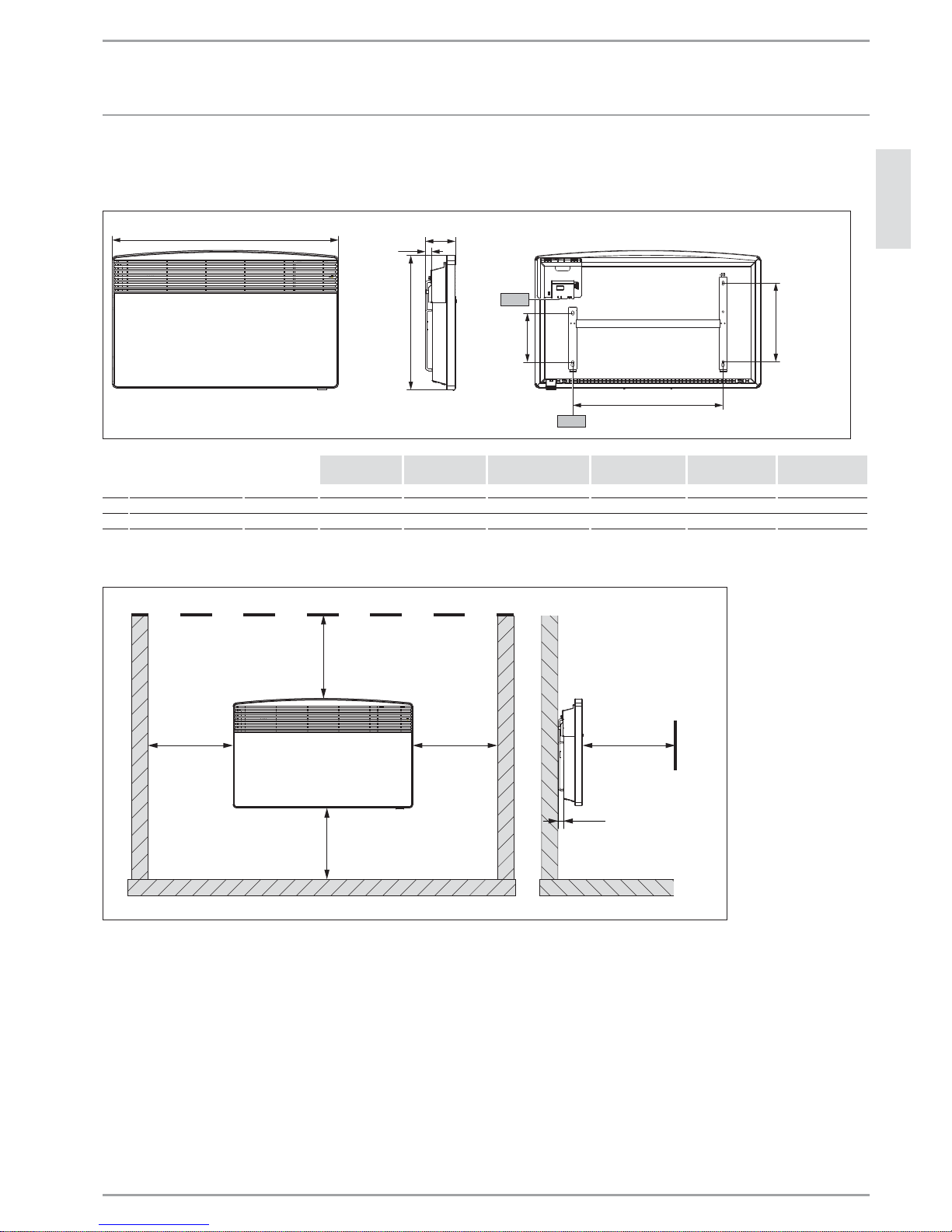
14.1 Dimensions
B01
A20
PLQLPXPÝ
(2 cm)
Ý (10 cm)
17.75Ý
(45 cm)
Ý
(16.3 cm)
Ý
(26.1 cm)
I13
D0000019277
CNS 50-2 E / CNS 75-2 E / CNS 100-1,-2 E / CNS 150-1,-2 E /
CNS 150-2 24H
CNS 200-2 E /
CNS 200-2 24H
CNS 240-2 E /
CNS 240-2 24H
A20 Appliance Width 14.5˝ / 37 cm 17.5˝ / 44.5 cm 17.5˝ / 445 cm 23.25 / 590 29.1 / 740 35.0 / 890
B01 Electrical cable entry
i13 Wall mounting bracket Hole spacing 4.75˝ / 121 cm 7.7˝ / 195 cm 7.7˝ / 195 cm 13.5˝ / 343 cm 19.3˝ / 491 cm 25.2˝ / 639 cm
14.2 Minimum clearances to hard surfaces
minimum. 10Ý
(25 cm)
minimum. 4Ý
(10 cm)
minimum. 4Ý
(10 cm)
minimum. 4Ý
(10 cm)
minimum. 20Ý
(50 cm)
minimum. 1Ý
(2 cm)
FLOOR
ANY HARD SURFACE
FLOOR
D0000019283_min
» The image above shows minimum allowed clearances between the installed appliance and any hard surfaces.
Page 10
10 |CNS E / CNS 24H WWW.STIEBEL-ELTRON-USA.COM
INSTALLATION
SPECIFICATIONS
14.3 Specifications
CNS E
Model CNS 50-2 E CNS 75-2 E CNS 100-1 E CNS 100-2 E CNS 150-1 E CNS 150-2 E CNS 200-2 E CNS 240-2 E
Item No. 231542 232068 233586 231543 233587 231544 231545 231546
Voltage 240 V 208 V 240 V 208 V 120 240 V 208 V 120 240 V 208 V 240 V 208 V 240 V 208 V
Wattage 0.5 kW 0.38 kW 0.75 kW 0.56 kW 1.0 kW 1.0 kW 0.75 kW 1.5 kW 1.5 kW 1.13 kW 2.0 kW 1.5 kW 2.4 kW 1.8 kW
Amperage 2.1 A 1.8 A 3.1 A 2.7 A 8.3 A 4.2 A 3.6 A 12.5 A 6.3 A 5.4 A 8.3 A 7.2 A 10.0 A 8.7 A
Required circuit breaker 15 A
Required wire size 14 AWG
Temperature range 43-86 °F/ 6-30 °C
Frost protection setting 47 °F/ 7 °C
IP-Rating IP24
Protection class I
Color alpine white
Height 17.75˝ / 45 cm
Width 14.5˝ / 37 cm 17.5˝ / 44.5 cm 17.5˝ / 44.5 cm 17.5˝ / 44.5 cm 23.25˝ / 59 cm 23.25˝ / 59 cm 29.1˝ / 74 cm 35.0˝ / 89 cm
Depth 4.0˝ / 10 cm
Weight 8.4 lb/ 3.8 kg 9.7 lb/ 4.4 kg 9.7 lb/ 4.4 kg 9.7 lb/ 4.4 kg 12.6 lb/ 5.7 kg 12.6 lb/ 5.7 kg 15.0 lb/ 6.8 kg 17.9 lb/ 8.1 kg
CNS 24H
Model
CNS 150-2 24H CNS 200-2 24H CNS 240-2 24H
Item No. 272063 272061 272060
Voltage 240 V 208 V 240 V 208 V 240 V 208 V
Wattage 1.5 kW 1.13 kW 2.0 kW 1.5 kW 2.4 kW 1.8 kW
Amperage 6.3 A 5.4 A 8.3 A 7.2 A 10.0 A 8.7 A
Required circuit breaker 15 A
Required wire size 14 AWG
Temperature range 43-86 °F/ 6-30 °C
Frost protection setting 47 °F/ 7 °C
IP-Rating IP24
Protection class I
Color alpine white
Height 17.75˝ / 45 cm
Width 23.25˝ / 59 cm 29.1˝ / 74 cm 35.0˝ / 89 cm
Depth 4.0˝ / 100 mm
Weight 12.6 lb/ 5.7 kg 15.0 lb/ 6.8 kg 17.9 lb/ 8.1 kg
Page 11
WWW.STIEBEL-ELTRON-USA.COM CNS E / CNS 24H| 11
ENGLISH
INSTALLATION
SPECIFICATIONS
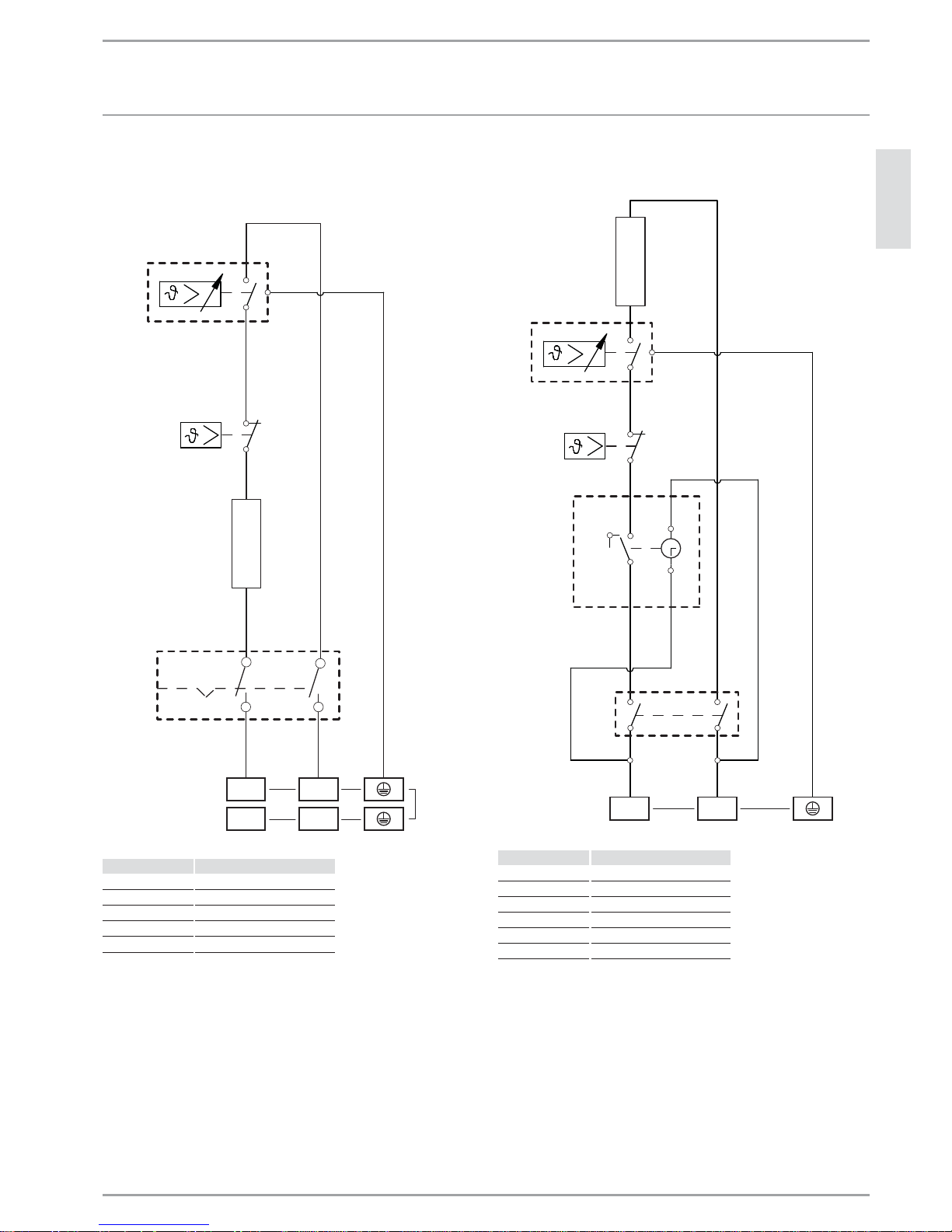
14.4 Wiring Diagram
14.4.1 CNS E Wiring Diagram
R1
N1
X1
220-240 V
120 V
F1
F2
L1 L2
L1 N
Label Description
F1 Thermal cut-out
F2 Thermostat
N1 On/off switch
R1 Heating element
X1 Terminal Block
14.4.2 CNS 24H Wiring Diagram
F2
R1
T1
1
2
3
4
5
F1
L1 L2
X1220-240 V
N1
Label Description
F1 Thermal cut-out
F2 Thermostat
N1 On/off switch
R1 Heating element
T1 24-hour timer
X1 Terminal Block
Page 12

17 West Street
West Hatfi eld, MA 01088
TOLL FREE 800.582.8423
PHONE 413.247.3380
FAX 413.247.3369
info
@
stiebel-eltron-usa.com
www.stiebel-eltron-usa.com
LIMITED WARRANTY
Subject to the terms and conditions set forth in this limited
warranty, Stiebel Eltron, Inc. (the “Manufacturer”) hereby
warrants to the original purchaser (the “Owner”) that
each Electric Space Heater (the “Heater”) shall be free of
defects in the Manufacturer’s materials or workmanship
for a period of three (3) years from the date of purchase.
As Owner’s sole and exclusive remedy for breach of the
above warranty, Manufacturer shall, at the Manufacturer’s
discretion, send replacement parts for local repair; retrieve
the unit for factory repair, or replace the defective Heater
with a replacement unit with comparable operating
features. Manufacturer’s maximum liability under all
circumstances shall be limited to the Owner’s purchase
price for the Heater.
This limited warranty shall be the exclusive warranty
made by the Manufacturer and is made in lieu of all other
warranties, express or implied, whether written or oral,
including, but not limited to warranties of merchantability
and fi tness for a particular purpose. Manufacturer shall
not be liable for incidental, consequential or contingent
damages or expenses arising directly or indirectly from any
defect in the Heater or the use of the Heater. Manufacturer
shall not be liable for any damage to property of Owner
arising, directly or indirectly, from any defect in the Heater
or the use of the Heater. Manufacturer alone is authorized
to make all warranties on Manufacturer’s behalf and no
statement, warranty or guarantee made by any other party
shall be binding on Manufacturer.
Manufacturer shall not be liable for any damage
whatsoever relating to or caused by:
1. any misuse or neglect of the Heater, any accident to
the Heater, any alteration of the Heater, or any other
unintended use;
2. acts of God and circumstances over
which Manufacturer has no control;
3. installation of the Heater other than as directed by
Manufacturer and other than in accordance with
applicable building codes;
4. failure to maintain the Heater or to operate the Heater
in accordance with the Manufacturer’s specifi cations;
5. improper installation and/or improper materials used
by any installer and not relating to defects in parts or
workmanship of Manufacturer;
6. moving the Heater from its original place of installation;
7. use on improper voltage or current;
8. disassembly, repair, or alteration by anyone other than
the manufacturer.
Should owner wish to return the Heater to manufacturer
for repair or replacement under this warranty, Owner
must fi rst secure written authorization from Manufacturer.
Owner shall demonstrate proof of purchase, including a
purchase date, and shall be responsible for all removal
and transportation costs. If Owner cannot demonstrate a
purchase date this warranty shall be limited to the period
beginning from the date of manufacture stamped on the
Heater. Manufacturer reserves the right to deny warranty
coverage upon Manufacturer’s examination of Heater.
This warranty is restricted to the Owner and cannot be
assigned.
Some States and Provinces do not allow the exclusion
or limitation of certain warranties. In such cases, the
limitations set forth herein may not apply to the Owner. In
such cases this warranty shall be limited to the shortest
period and lowest damage amounts allowed by law. This
warranty gives you specifi c legal rights and you may also
have other rights which vary from State to State or Province
to Province.
Owner shall be responsible for all labor and other charges
incurred in the removal or repair of the Heater in the fi eld.
This Warranty is valid for U.S.A. & Canada only. Warranties
may vary by country. Please consult your local Stiebel Eltron
Representative for the Warranty for your country.
WARRANTY AND CUSTOMER SERVICE - ENVIRONMENT AND RECYCLING
12 |CNS E / CNS 24H WWW.STIEBEL-ELTRON-USA.COM
Environment and recycling
We would ask you to help protect the environment. After use,
dispose of the various materials in accordance with national
regulations.
!
The installation, electrical connection and first
operation of this appliance should be carried out by
a qualified installer.
!
The company does not accept liability for failure of
any goods supplied which have not been installed
and operated in accordance with the manufacturer’s
instructions.
15. Warranty
Page 13

WWW.STIEBEL-ELTRON-USA.COM CNS E / CNS 24H| 13
ESPAÑOL
CONTENTS | OPERATION
INSTRUCCIONES IMPORTANTES
OPE RACIÓN
1. INSTRUCCIONES IMPORTANTES
GUARDE ESTAS INSTRUCCIONES
Siempre que se utilizan artefactos eléctricos, se deben tomar
precauciones básicas para reducir los riesgos de incendio, shock
eléctrico y lesiones personales, incluyendo las siguientes:
1. Lea todas las instrucciones antes de instalar o utilizar el
calefactor.
2. El calefactor se calienta cuando está funcionando. Para prevenir
quemaduras, evite que la piel desnuda entre en contacto con las
superficies calientes. Mantenga materiales combustibles, tales
como muebles, almohadas, ropa de cama, papeles, ropa, etc.
y cortinas a una distancia de al menos 1 m (3 ft) del frente del
calefactor, y a una distancia de al menos 1 m (3 ft) de los laterales
y la parte posterior del artefacto.
3. Se deben tomar precauciones extremas cuando cualquier
calefactor es utilizado por o cerca de niños o personas
discapacitadas y cuando el calefactor se deja funcionando y sin
vigilancia.
4. No utilice ningún calefac tor que haya tenido un funcionamiento
defectuoso. Desconecte la energía del panel de servicio y haga que
un electricista confiable lo revise antes de reutilizarlo.
1.1 Información del documento
El capítulo Operación está destinado a usuarios y técnicos en
calefacción.
El capítulo Instalación está destinado a técnicos en calefacción.
Lea las instrucciones cuidadosamente antes de utilizar
el artefacto y guárdelas para consultas futuras. Pásele
las instrucciones a cualquier nuevo usuario.
1.2 Explicación de símbolos
1.2.1 Presentación de la información de seguridad
La información de seguridad comprende un símbolo de advertencia,
una palabra clave y un texto informativo. La información de
seguridad está impresa sobre un fondo gris.
Ejemplo:
PELIGRO: Choque Eléctrico
DESCONECTE TODOS LOS POLOS DE LA FUENTE
DE ALIMENTACIÓN.
12 3
4
1 Símbolo (ver capítulo sobre símbolos de advertencia/
símbolos)
2 Palabra clave (ver capítulo sobre palabras clave)
3 Descripción (ver capítulo sobre símbolos de advertencia/
símbolos)
4 Texto informativo
OPERACIÓN
1. INSTRUCCIONES IMPORTANTES _______________________________2
1.1 Información del documento ______________________________________ 2
1.2 Explicación de símbolos ___________________________________________ 2
2. Seguridad ________________________________________________________3
2.1 Uso previsto _________________________________________________________ 3
2.2 Información de seguridad ________________________________________ 3
2.3 Certificación ETL / UL ______________________________________________ 4
2.4 Etiqueta de características _______________________________________ 4
3. Registre su producto ___________________________________________4
4. Descripción del artefacto ______________________________________4
5. Operación ________________________________________________________4
5.1 Descripción de la interface de usuario _________________________ 4
5.2 Protección anticongelante ________________________________________ 4
5.3 Limitación del controlador de temperatura ___________________ 4
5.4 Apagado ______________________________________________________________ 5
6. CNS 24H Operación _____________________________________________5
6.1 Modos de operación _______________________________________________ 5
6.2 Interruptor del temporizador ____________________________________ 5
6.3 Selector de temperatura __________________________________________ 5
6.4 Protección anticongelante ________________________________________ 5
6.5 Limitación del controlador de temperatura ___________________ 6
6.6 Apagado ______________________________________________________________ 6
7. Limpieza, cuidado y mantenimiento __________________________6
8. Qué hacer si ... __________________________________________________6
INSTALLACIÓN
9. Seguridad ________________________________________________________7
9.1 Instrucciones de seguridad general ____________________________ 7
9.2 Instrucciones, estándares y normativa _________________________ 7
10. Descripción del artefacto ______________________________________7
10.1 Entrega estándar ___________________________________________________ 7
11. Instalación _______________________________________________________7
11.1 Instalación del soporte para montaje en pared ______________ 7
11.2 Instalación del artefacto __________________________________________ 8
11.3 Desmontaje del artefacto _________________________________________ 8
11.4 Suministro de energía _____________________________________________ 8
11.5 Bloque de terminales ______________________________________________ 8
12. Resolución de problemas ______________________________________ 8
13. Traspaso del artefacto _________________________________________8
14. Especificaciones ________________________________________________9
14.1 Dimensiones de la versión de pared ___________________________ 9
14.2 Distancias mínimas ________________________________________________ 9
14.3 Tabla de especificaciones ________________________________________10
14.4 Plano eléctrico _____________________________________________________ 11
15. Garantía________________________________________________________ 12
Page 14

OPERACIÓN
SEGURIDAD
14 |CNS E / CNS 24H WWW.STIEBEL-ELTRON-USA.COM
1.2.2 Palabras clave
PALABRA CLAVE Descripc ión
PELIGRO
La palabra clave PELIGRO indica información que debe
respetarse, ya que de lo contrario pueden producirse
lesiones serias o incluso la muerte.
ADVERTENCIA
La palabra clave ADVERTENCIA indica información
que debe respetarse, ya que de lo contrario pueden
producirse lesiones serias o incluso la muerte.
PRECAUCIÓN
La palabra clave PRECAUCIÓN indica información
que debe respetarse, ya que de lo contrario pueden
producirse lesiones relativamente serias o leves.
1.2.3 Símbolos de advertencia/símbolos
Símbolo de advertencia
Descripción
Lesiones
Electrocución
Quemaduras o escaldaduras
!
Otras situaciones
Incendio
Nunca cubra el artefacto
Desecho del artefacto
1.2.4 Símbolos de texto y su presentación en esta
documentación
Lea el texto que está junto a este símbolo
cuidadosamente.
» El símbolo “»” indica que usted debe realizar alguna acción. La
acción que debe realizar se describe paso a paso.
— Los pasajes que contienen el símbolo “–” le presentan listas
de ítems.
1.2.5 Información sobre el artefacto
Nunca cubra el artefacto
1.2.6 Unidades de medida
Las dimensiones se indican en este documento en
in. / mm. Cualquier unidad de medida alternativa se
especifica según el caso.
2. Seguridad
2.1 Uso previsto
Este artefacto está diseñado para calefaccionar espacios en
viviendas.
Cualquier otro uso diferente del descripto será considerado
inapropiado. El cumplimiento de estas instrucciones es también
parte del uso correcto de este artefacto. Cualquier modificación
o transformación del artefacto invalida todos los derechos de
garantía.
2.2 Información de seguridad
Utilice el artefacto solamente una vez que se encuentra
completamente instalado y con todos los dispositivos de seguridad
colocados.
El calentador de agua debe instalarse correctamente antes de
su uso.
PELIGRO: Electrocución
Antes de la limpieza, asegúrese de que la corriente
esté desconectada en el panel del interruptor y de
que el elemento de calentamiento del calentador
esté frío.
ADVERTENCIAL: Incendio
Nunca opere el artefacto ...
...en habitaciones donde el artefacto esté en
riesgo de incendio o explosión como resultados de
productos químicos, polvos, gases o vapores.
...en proximidad inmediata de cañerías o recipientes
que transportan o contienen materiales inflamables
o explosivos.
...si en la habitación donde está instalado se están
realizando trabajos tales como tendido de cables,
molienda o sellado.
...si se utilizan aerosoles, lustra pisos o productos
similares que contienen napsan. Ventile bien la
habitación antes de calefaccionar.
...si no se mantienen las holguras mínimas respecto
de las superficies de objetos adyacentes, como ser
muebles, cortinas de red, cortinas, textiles u otros
materiales inflamables (véase 14.2, “Distancias
mínimas”, pág. 20).
...si un componente del artefacto está dañado, el
artefacto se ha caído o ya tenía una falla.
ADVERTENCIAL: Incendio
Nunca coloque objetos o materiales inflamables,
combustibles o aislantes, tales como ropa, ropa de
cama, revistas, recipientes con lustra pisos o napsan,
latas de aerosol o similares sobre el artefacto o en
proximidad inmediata al mismo.
ADVERTENCIA: Quemaduras
Las superficies de la carcasa del artefacto y el aire
expulsado se calientan durante el funcionamiento
(más de 80 °C / 176 °F).
PRECAUCIÓN Sobrecalentamiento
Nunca cubra el artefacto.
Nunca pise el artefacto.
Page 15

OPERACIÓN
REGISTRE SU PRODUCTO
WWW.STIEBEL-ELTRON-USA.COM CNS E / CNS 24H| 15
ESPAÑOL
2.3 Certificación ETL / UL
La certificación ETL / UL indica que el artefacto cumple con todos
los requisitos esenciales según el estándar UL 499.
2.4 Etiqueta de características
La placa de características está ubicada en la parte derecha del
exterior del artefacto.
3. Registre su producto
Debe registrar este producto en nuestro sitio
web dentro de 90 días de la compra para activar
la garantía estándar o para ser elegible para la
garantía extendida. Vaya a nuestro sitio web a:
www.stiebel-eltron-usa.com y haga clic en “register
your product”.
Antes de comenzar el proceso de registración, le sugerimos que
reuna la información necesaria, tal y como sigue:
Tipo, Ejemplo: CNS 100-2 E (de la etiqueta blanca que se encuentra en la derecha de la unidad)
Número que aparece después de “Nr.”
Lugar de compra
Fecha de compra
Nombre y apellido
Dirección de correo electrónico
Dirección física
Número de teléfono
SI TIENE ALGUNA PREGUNTA SOBRE EL PROCESO DE REGISTRACIÓN O LAS OPCIONES DE GARANTÍA, POR FAVOR CONTACTAR A STIEBEL ELTRON EE.UU. AL (800)-582-8423.
4. Descripción del artefacto
El artefacto es un calefactor eléctrico directo para ser instalado
únicamente en una pared.
El artefacto es adecuado como sistema de calefacción general para
baños, por ejemplo, o para ser usado entre estaciones, o como
calefactor complementario en habitaciones pequeñas, como una
sala de juegos o una habitación de huéspedes.
El aire es calentado dentro del artefacto por un elemento
calefactor y luego es expulsado por convección natural a través
de una rejilla de salida en la parte superior. El aire fresco de la
habitación ingresa a través de las aberturas de la parte inferior
del artefacto.
Después de instalar el artefacto en la pared y realizar la conexión
eléctrica utilizando un suministro permanente de energía mediante
un enchufe adecuado para artefactos, el mismo se encuentra listo
para operar.
5. Operación
El CNS 24H es un calentador de convección con termostato y un
interruptor de encendido / apagado.
5.1 Descripción de la interface de usuario
» Encienda el artefacto colocando en ON la llave que se encuentra
en el lado derecho del mismo.
» Seleccione la temperatura deseada utilizando el selector
de temperatura de variación continua (para consultar las
temperaturas vea el capítulo de especificaciones).
26_07_31_0037
Tan pronto como se alcanza la temperatura elegida en la habitación,
la misma se mantiene en forma constante mediante calentamientos
periódicos (la salida del artefacto debe corresponder al menos con
la demanda de calor de la habitación).
Si se instalan varios artefactos en un mismo ambiente, la
temperatura seleccionada en cada artefacto puede ser diferente.
Para evitar el consumo excesivo de energía cuando las ventanas se
encuentren abiertas, se debería apagar el artefacto para ventilar.
5.2 Protección anticongelante
Gire el selector de temperatura lo más hacia la derecha posible. En
esta posición, el controlador de temperatura enciende el elemento
calefactor en forma automática si la temperatura en la habitación
cae por debajo de la temperatura de protección anticongelante
(47 °F / 7 °C).
5.3 Limitación del controlador de temperatura
Se puede fijar el controlador de temperatura en una posición
determinada o limitar el rango de variación de temperaturas
utilizando dos pines ubicados en la parte posterior de la carcasa.
» Retire los pines.
» Para fijar la temperatura elegida, coloque un pin en el orificio
opuesto (ver diagrama).
1
1
2
26_07_31_0038
1 Tope
2 Selector de temperatura
Page 16

OPERACIÓN
CNS 24H OPERACIÓN
16 |CNS E / CNS 24H WWW.STIEBEL-ELTRON-USA.COM
» Para limitar el rango de variación de temperatura, elija los
valores máximo y mínimo con el selector de temperatura e
inserte un pin para cada uno en los orificios que se encuentran
ligeramente desplazados en el lado opuesto (ver diagrama).
26_07_31_0171
1
1
2
1 Tope
2 Selector de temperatura
5.4 Apagado
» Coloque la llave que se encuentra en el lado derecho del
artefacto en la posición OFF.
6. CNS 24H Operación
El CNS 24H es un calentador de convección con un temporizador
de 24 horas, termostato y un interruptor de encendido / apagado.
Para apagar el aparato, coloque el interruptor de
encendido/apagado en
.
6.1 Modos de operación
12
13
14
2
1
3
3
2
1 Interruptor del temporizador
2 Interruptor de encendido/apagado
3 Indicador de la hora
Calefacción con temporizador
» Para activar el modo temporizador, coloque el interruptor de
encendido/apagado en el
símbolo. El aparato se enciende
de acuerdo a la configuración del temporizador (véase 6.2,
“Interruptor del temporizador”, pág. 16).
Apagado del aparato
» Para apagar el aparato, coloque el interruptor de encendido/
apagado en
. En este modo, la protección anticongelante está
desactivada.
Funcionamiento constante
» Para que el aparato funcione en forma constante, coloque el
interruptor de encendido/apagado en
. El aparato estará en
funcionamiento hasta que se alcance la temperatura elegida. En
este modo, la protección anticongelante está activada.
6.2 Interruptor del temporizador
En el modo temporizador y el modo constante, el aparato
calienta hasta alcanzar la temperatura elegida (en el selector de
temperatura).
Cuando se encuentra en el modo temporizador, el aparato se activa
solamente durante el tiempo deseado y hasta la temperatura
elegida.
» Para ajustar el tiempo, gire el interruptor del temporizador hacia
la derecha, hasta que la flecha negra apunte a la hora actual.
» Levante las pestañas que se encuentran en el borde del
temporizador para indicar el tiempo que el aparato debe
funcionar. Cada pestaña corresponde a un período de encendido
o apagado de 20 minutos.
Calefacción encendida: levantar las pestañas
Calefacción apagada: bajar las pestaña
6.3 Selector de temperatura
» Seleccione la temperatura ambiente deseada con el selector
de temperatura de variación continua (para consultar las
temperaturas, ver el capítulo de especificaciones).
26_07_31_0037
En cuanto se alcanza la temperatura ambiente elegida, esta
temperatura se mantiene en forma constante mediante
calentamientos periódicos (la salida del aparato debe corresponder
al menos con la demanda de calor del ambiente).
Si hay varios aparatos instalados en un mismo ambiente, no es
necesario seleccionar la misma temperatura en todos los aparatos.
Para evitar el consumo excesivo de energía, debería apagar el
aparato cuando las ventanas se encuentran abiertas.
6.4 Protección anticongelante
» Gire el selector de temperatura lo más hacia la derecha posible.
En esta posición, el controlador de temperatura enciende el
elemento calefactor en forma automática si la temperatura
ambiente cae por debajo de la temperatura de protección
anticongelante (47 °F / 7 °C).
Page 17

WWW.STIEBEL-ELTRON-USA.COM CNS E / CNS 24H| 17
ESPAÑOL
INSTALACIÓN
LIMPIEZA, CUIDADO Y MANTENIMIENTO
6.5 Limitación del controlador de temperatura
Se puede fijar el controlador de temperatura en una posición
determinada o limitar el rango de temperaturas utilizando dos
topes que se encuentran en la parte posterior de la carcasa.
» Retire los topes.
» Para fijar la temperatura elegida, coloque un tope en el orificio
que se encuentra en el lado opuesto (ver diagrama).
1
1
2
26_07_31_0038
1 Tope
2 Selector de temperatura
» Para limitar el rango de temperaturas, elija los valores mínimo
y máximo en el selector de temperatura y coloque un tope
para cada valor en el orificio que se encuentra ligeramente
desplazado en el lado opuesto (ver diagrama).
26_07_31_0171
1
1
2
1 Tope
2 Selector de temperatura
6.6 Apagado
» Coloque el interruptor que se encuentra en el lado derecho del
aparato en la posición
.
7. Limpieza, cuidado y mantenimiento
!
ADVERTENCIA:
Antes de comenzar a limpiar, asegúrese que
se ha desconectado la energía en el panel del
circuito disyuntor y que el elemento calentador
del calefactor este frío. No hacerlo puede resultar
en quemaduras severas, electrocución, lesiones
corporales severas o muerte.
Si aparece una decoloración clara con tintes marrones en la
carcasa del artefacto, límpiela tan pronto como sea posible con
un paño húmedo. Limpie el artefacto una vez que está frío con
productos de limpieza habituales. Evite utilizar productos de
limpieza abrasivos o corrosivos.
PRECAUCIÓN: Incendio
Nunca rocíe aerosol de limpieza en la ranura del
aire. Asegúrese que no pueda entrar humedad al
artefacto.
Como parte del mantenimiento habitual, recomendamos que
también se revisen los componentes de control. Los componentes
de seguridad y control deben ser revisados por un contratista no
más allá de diez años después de la puesta en funcionamiento.
8. Qué hacer si ...
... el artefacto no calienta:
Verifique la temperatura a la que se reguló el artefacto y la caja
del disyuntor del circuito.
El artefacto tiene un control de seguridad de temperatura que
lo apaga si se sobrecalienta. Después que se eliminó la causa
(por ejemplo se encontraban cubiertas las aberturas de entrada
o salida de aire) y el artefacto se enfrió durante unos minutos, se
reanuda la operación.
Si no puede solucionar la falla, contacte a su contratista.
Para facilitar y agilizar su consulta, por favor suminístrele
el número que se encuentra en la placa de características
(000000-0000-000000).
Page 18

18 |CNS E / CNS 24H WWW.STIEBEL-ELTRON-USA.COM
INSTALACIÓN
SEGURIDAD
INSTALLACIÓN
9. Seguridad
La instalación, puesta en marcha, mantenimiento y reparación del
artefacto debe ser realizada solamente por contratistas calificados.
9.1 Instrucciones de seguridad general
Garantizamos el funcionamiento sin problemas y la seguridad
operativa solamente si se utilizan los accesorios originales y los
repuestos previstos para el artefacto.
PELIGRO: Electrocución
Si instala el artefacto en la pared, hágalo de modo
tal que los dispositivos de control no puedan ser
tocados por una persona que esté en la bañera o en
la ducha.
!
PRECAUCIÓN:
-Solamente amure el artefacto a una pared vertical
que resista temperaturas de al menos 185 °F / 85 °C.
-Respete las holguras mínimas respecto de las
superficies de objetos adyacentes (por holguras
mínimas ver el capítulo de especificaciones).
-Nunca instale el artefacto justo debajo de un
tomacorriente.
-Asegúrese que el cable de alimentación no esté en
contacto con componente alguno del artefacto.
9.2 Instrucciones, estándares y normativa
Respete todas las normas e instrucciones nacionales
y regionales aplicables.
Respete la Normativa de Construcción de Edificios y
Garajes (o normativa local que corresponda).
10. Descripción del artefacto
10.1 Entrega estándar
Soporte para montaje en pared (enganchado en el artefacto)
11. Instalación
11.1 Instalación del soporte para montaje en pared
El soporte puede usarse también como una plantilla para montar
el artefacto en la pared; esto asegura la distancia requerida al
piso.
» Desenganche el soporte para montaje en pared.
» Apoye el nivel del soporte para montaje en pared centrado sobre
el piso y marque los orificios 1 y 2.
» Levante el soporte de modo tal que los orificios inferiores se
superpongan a las marcas que acaba de hacer en la pared donde
se va a realizar la instalación.
» Marque los orificios 3 y 4 en la pared de instalación.
aaa
26_07_31_0124
1
3
2
4
» Perfore la pared en los cuatro puntos marcados utilizando
un taladro. Asegure el soporte con implementos adecuados
(tornillos, tacos) dependiendo del tipo de pared. Las ranuras
verticales le permiten compensar desplazamientos en los
orificios de sujeción.
Page 19

WWW.STIEBEL-ELTRON-USA.COM CNS E / CNS 24H| 19
ESPAÑOL
INSTALACIÓN
RESOLUCIÓN DE PROBLEMAS
11.2 Instalación del artefacto
» Enganche el artefacto por medio de las ranuras ubicadas en
la parte trasera a las cuatro lengüetas del soporte en forma
simultánea.
» Empuje el artefacto para trabarlo en posición.
» Gire completamente el perno de bloqueo del soporte en la
dirección de las agujas del reloj; esto traba el artefacto en su
lugar.
» Presione la tapa de seguridad sobre el perno de bloqueo para
impedir que se afloje.
26_07_31_0035
1
2
1 Perno de bloqueo
2 Soporte para montaje en pared
26_07_31_0127
1
2
3
1 Artefacto
2 Tapa de seguridad
3 Perno de bloqueo
11.3 Desmontaje del artefacto
» Retire la tapa de seguridad del perno de bloqueo.
26_07_31_0128
1
2
3
1 Artefacto
2 Tapa de seguridad
3 Perno de bloqueo
» Destrabe el perno de bloqueo del soporte para montaje en
pared.
» Levante el artefacto ligeramente y tírelo hacia adelante,
alejándolo del soporte.
11.4 Suministro de energía
» Asegúrese que el cable de alimentación de la instalación tenga
una sección transversal adecuada.
» Asegúrese que haya un tomacorriente o caja de conexión para
el suministro permanente de energía instalado a una distancia
de al menos 10 cm/ 4 in del costado del artefacto.
11.5 Bloque de terminales
Se recomienda usar cable trenzado para conectar al bloque de
terminales. Engarce una férula sobre cable trenzado pelado para
asegurar una buena conexión.
Consulte el siguiente diagrama para ver el nivel recomendado de
torsión en los tornillos del bloque de terminales.
Diámetro del cable (mm) Torsión (N•cm) Torsión
(lbf•in)
2.8 30-40 2.65-3.54
2.8-3 35-50 3.09-4.42
3-3.2 50-60 4.42-5.31
3.2-3.6 60-80 5.31-7.08
3.6-4.1 90-120 7.96-10.62
4.1-4.7 120-180 10.62-15.93
4.7-5.3 150-200 13.27-17.7
Usar las especificaciones de torsión adecuadas para fijar el cable
al bloque de cableado ayuda a evitar pérdidas personales o daños
a la propiedad.
Consulte las tablas de la sección 13.4, pág. 23 para ver
información sobre el calibre adecuado para los cables.
PELIGRO: Electrocución
Llevar a cabo todas las conexiones eléctricas e
instalación de acuerdo con todos los códigos de
construcción nacionales, estatales y locales.
PELIGRO: Electrocución
Cada calentador debe ser conectado directamente
al panel de interruptores de circuito usando el
interruptor y calibre del cable adecuados.
PELIGRO: Electrocución
No enchufe el calentador en un enchufe de la pared.
El voltaje especificado en la placa de identificación
debe coincidir con el voltaje en el panel de
interruptores.
12. Resolución de problemas
El cable de alimentación debe ser reemplazado solamente por un
contratista utilizando nuestros repuestos originales.
Si no puede solucionar la causa, llame al instalador. Para poder
ayudarle mejor y con mayor agilidad, indique el número de la
placa de modelo (000000-0000-000000).
13. Traspaso del artefacto
Explique las funciones del artefacto al usuario. Haga especial
hincapié en la información de seguridad. Entregue las instrucciones
de operación e instalación al usuario.
Page 20

20 |CNS E / CNS 24H WWW.STIEBEL-ELTRON-USA.COM
INSTALACIÓN
ESPECIFICACIONES
14. Especificaciones
14.1 Dimensiones de la versión de pared
B01
A20
PLQLPXPÝ
(2 cm)
Ý (10 cm)
17.75Ý
(45 cm)
Ý
(16.3 cm)
Ý
(26.1 cm)
I13
D0000019277
CNS 50-2 E CNS 75-2 E CNS 100-1,-2 E CNS 150-1,-2 E /
CNS 150-2 24H
CNS 200-2 E /
CNS 200-2 24H
CNS 240-2 E /
CNS 240-2 24H
A20 Artefacto Ancho 14.5˝ / 37 cm 17.5˝ / 44.5 cm 17.5˝ / 445 cm 23.25 / 590 cm 29.1 / 740 cm 35.0 / 890 cm
B01 Entrada del cable de corriente
i13
Soporte para el
montaje en pared
Distancia entre
orificios
4.75˝ / 121 cm 7.7˝ / 195 cm 7.7˝ / 195 cm
13.5˝ / 343 cm 19.3˝ / 491 cm 25.2˝ / 639 cm
14.2 Distancias mínimas
mínimo. 10Ý
(25 cm)
mínimo. 4Ý
(10 cm)
mínimo. 4Ý
(10 cm)
mínimo. 4Ý
(10 cm)
mínimo. 20Ý
(50 cm)
mínimo. 1Ý
(2 cm)
SUELO
CUALQUIER SUPERFICIE DURA
SUELO
D0000019283_min
» La imagen de arriba muestra las distancias mínimas permitidas entre el aparato instalado y cualquier superficies dura.
Page 21

WWW.STIEBEL-ELTRON-USA.COM CNS E / CNS 24H| 21
ESPAÑOL
INSTALACIÓN
ESPECIFICACIONES
14.3 Tabla de especificaciones
CNS E
Modelo CNS 50-2 E CNS 75-2 E CNS 100-1 E CNS 100-2 E CNS 150-1 E CNS 150-2 E CNS 200-2 E CNS 240-2 E
# Catálogo 231542 232068 233586 231543 233587 231544 231545 231546
Voltaje 240 V 208 V 240 V 208 V 120 V 240 V 208 V 120 V 240 V 208 V 240 V 208 V 240 V 208 V
Potencia 0.5 kW 0.38 kW 0.75 kW 0.56 kW 1.0 kW 1.0 kW 0.75 kW 1.5 kW 1.5 kW 1.13 kW 2.0 kW 1.5 kW 2.4 kW 1.8 kW
Amperaje 2.1 A 1.8 A 3.1 A 2.7 A 8.3 A 4.2 A 3.6 A 12.5 A 6.3 A 5.4 A 8.3 A 7.2 A 10.0 A 8.7 A
Interruptor auto. #
requerido
15 A
Calibre de alambre 14 AWG
Rango de temperatura 43-86°F / 6-30°C
Ajuste de protección
anticongelante
47°F / 7 °C
Altura 17.75˝ / 45 cm
Calificación IP IP24
Clase de protección I
Color blanco alpin
Ancho 14.5˝ / 37 cm 17.5˝ / 44.5 cm 17.5˝ / 44.5 cm 17.5˝ / 44.5 cm 23.25˝ / 59 cm 23.25˝ / 59 cm 29.1˝ / 74 cm 35.0˝ / 89 cm
Profundidad 4.0˝ / 10 cm
Peso 8.4 lb / 3.8 kg 9.7 lb / 4.4 kg 9.7 lb / 4.4 kg 9.7 lb / 4.4 kg 12.6 lb / 5.7 kg 12.6 lb / 5.7 kg 15.0 lb / 6.8 kg 17.9 lb / 8.1 kg
CNS 24H
Modelo
CNS 150-2 24H CNS 200-2 24H CNS 240-2 24H
# Catálogo 272063 272061 272060
Voltaje 240 V 208 V 240 V 208 V 240 V 208 V
Potencia 1.5 kW 1.13 kW 2.0 kW 1.5 kW 2.4 kW 1.8 kW
Amperaje 6.3 A 5.4 A 8.3 A 7.2 A 10.0 A 8.7 A
Interruptor auto. #
requerido
15 A
Calibre de alambre 14 AWG
Rango de temperatura 43-86 °F/ 6-30 °C
Ajuste de protección
anticongelante
47 °F/ 7 °C
Altura IP24
Calificación IP I
Clase de protección blanco alpin
Color 17.75˝ / 45 cm
Ancho 23.25˝ / 59 cm 29.1˝ / 74 cm 35.0˝ / 89 cm
Profundidad 4.0˝ / 100 mm
Peso 12.6 lb/ 5.7 kg 15.0 lb/ 6.8 kg 17.9 lb/ 8.1 kg
Page 22

22 |CNS E / CNS 24H WWW.STIEBEL-ELTRON-USA.COM
INSTALACIÓN
ESPECIFICACIONES
14.4 Plano eléctrico
14.4.1 Plano eléctrico CNS E
R1
N1
X1
220-240 V
120 V
F1
F2
L1 L2
L1 N
Label Description
F1 Protección sobrecalentamiento
F2 Regulador de temperatura
N1 Interruptor de encendido/apagado
R1 Resistencia calefactora
X1 Bloque de terminales
14.4.2 Plano eléctrico CNS 24H
F2
R1
T1
1
2
3
4
5
F1
L1 L2
X1220-240 V
N1
Label Description
F1 Protección sobrecalentamiento
F2 Regulador de temperatura
N1 Interruptor de encendido/apagado
R1 Resistencia calefactora
T1 Temporizador 24 horas
X1 Bloque de terminales
Page 23

WWW.STIEBEL-ELTRON-USA.COM CNS E| / CNS 24H 23
ESPAÑOL
TABLA DE ESPECIFICACIONES | GARANTÍA
MEDIO AMBIENTE Y RECICLAJE
!
La instalación, conexión eléctrica y primera
operación de este artefacto debe ser realizada
por un instalador calificado.
!
La compañía no acepta responsabilidad alguna por
la falla de cualquier artículo suministrado que no
haya sido instalado y operado de acuerdo con las
instrucciones del fabricante.
Medioambiente y reciclaje
Por favor ayúdenos a proteger el medioambiente eliminando el
embalaje en concordancia con la normativa nacional para el
tratamiento de residuos.
GARANTÍA LIMITADA
Sujeto a los términos y condiciones expresados en esta
garantía limitada, Stiebel Eltron, Inc. (el “Fabricante”)
por la presente asegura al comprador original (el
“Propietario”) que cada calentador eléctrico de ambiente
(el “Calentador”) estará libre de defectos en los materiales
del Fabricante o la mano de obra durante un período de
tres (3) años a partir de la fecha de compra. Como única y
exclusiva solución para el Propietario por incumplimiento
de la presente garantía, el Fabricante, a discreción del
Fabricante, enviará repuestos para reparación local,
recuperará la unidad para su reparación en fábrica o
reemplazará el Calentador defectuoso con una unidad de
reemplazo que tenga características de funcionamiento
comparables. La máxima responsabilidad del Fabricante en
cualquier circunstancia se limitará al precio de compra del
Calentador que pagó el Propietario.
Esta garantía limitada será la única garantía que ofrece
el Fabricante y reemplaza a todas las demás garantías,
expresas o implícitas, escritas u orales oral, incluidas pero
no limitadas las garantías de comerciabilidad y aptitud
para determinado fi n. El Fabricante no será responsable
de daños incidentales, consecuentes o contingentes o
gastos que surjan directa o indirectamente de cualquier
defecto del Calentador o el uso de este. El Fabricante no
será responsable de cualquier daño a la propiedad del
Propietario que surja directa o indirectamente de cualquier
defecto del Calentador o el uso de este. Solo el Fabricante
está autorizado a ofrecer todas las garantías de parte
del Fabricante y ninguna afi rmación, garantía o promesa
realizada por cualquier otra parte será vinculante para el
Fabricante.
El Fabricante no será responsable por daños de ningún
tipo relacionados u ocasionados por:
1. cualquier uso indebido o falta de cuidado del
Calentador, cualquier accidente que afecte al
Calentador, cualquier alteración del Calentador o
cualquier otro uso incorrecto;
2. casos fortuitos o circunstancias sobre las cuales el
Fabricante no tiene control;
3. instalación del del Calentador que se desvíe de las
directivas del Fabricante y no observe los códigos de
construcción pertinentes;
4. falta de mantenimiento del Calentador o
funcionamiento del Calentador que no sea conforme a
las especifi caciones del Fabricante;
5. instalación defectuosa y/o uso de materiales
inapropiados por parte de cualquier instalador y que no
se relacionen con defectos en los repuestos o la mano
de obra del Fabricante;
6. cambio del Calentador de su lugar original de
instalación;
7. funcionamiento en un voltaje o corriente inapropiada;
8. desarmado, reparación o alteración por cualquier
persona que no sea el Fabricante.
Si el Propietario desea devolver el Calentador al Fabricante
para su reparación o reemplazo bajo los términos de
esta garantía, el Propietario debe obtener primero la
autorización por escrito del Fabricante. El Propietario
deberá presentar una prueba de compra que incluya la
fecha de compra, y será responsable de todos los costos
de desinstalación y transporte. Si el Propietario no puede
demostrar la fecha de compra, esta garantía se limitará
al período que corre a partir de la fecha de fabricación
impresa en el Calentador. El Fabricante se reserva el
derecho de negar la cobertura de esta garantía después
de examinar el Calentador. Esta garantía se limita al
Propietario y no puede transferirse.
Algunos estados y provincias no permiten la exclusión
o limitación de ciertas garantías. En tales casos, las
limitaciones aquí expresadas pueden no aplicarse al
Propietario. En tales casos, esta garantía se limitará al
período más corto y a los importes por daños más cortos
permitidos por ley. Esta garantía le otorga derechos legales
específi cos y puede que usted tenga otros derechos, que
varían de estado y de provincia a provincia.
El Propietario será responsable de todos los costos de
mano de obra y otros cargos incurridos al retirar o reparar
el Calentador en su domicilio.
Esta Garantía solo es válida en Estados Unidos y Canadá.
Las garantías pueden variar de un país a otro. Consulte a su
representante de Stiebel Eltron local para conocer la Garantía
correspondiente a su país.
15. Garantía
Page 24

24 |CNS E / CNS 24H WWW.STIEBEL-ELTRON-USA.COM
TABLE DES MATIÈRES | MODE D’EMPLOI
DIRECTIVES IMPORTANTES
UTILISATION
1. DIRECTIVES IMPORTANTES
GARDER CES DIRECTIVES POUR
RÉFÉRENCE ULTÉRIEURE.
Pour réduire le risque d’incendie, de choc électrique ou de
blessures, respectez les directives suivantes lorsque vous utilisez
des appareils électriques :
1. Lire toutes les instructions avant d’installer ou d’utiliser cet
appareil de chauffage.
2. Cet appareil est chaud lorsqu’il est en marche. Pour éviter de
vous brûler, ne touchez pas les surfaces chaudes avec la peau
nue. Gardez les matériaux combustibles, comme les meubles, les
coussins, la literie, le papier, les vêtements, etc. et les rideaux à au
moins 1 m (3 pi) de distance du devant de l’appareil de chauffage
et au moins à 1 m (3 pi) de distance latéralement et à l’arrière.
3. Prenez de grandes précaution lorsque tout appareil de chauffage
doit être utilisé en présence ou par des enfants ou des personnes
invalides, ainsi que chaque fois qu’il est laissé en marche sans
surveillance.
4. Ne faites pas fonctionner tout appareil de chauffage qui aurait
mal fonctionné préalablement. Débranchez le cordon électrique à
la prise et faites examiner l’appareil par un électricien de bonne
réputation avant de le réutiliser.
1.1 Généralités à propos de ce document
Le chapitre Mode d’emploi est à l’attention des utilisateurs et des
entrepreneurs en systèmes de chauffage.
Le chapitre Installation est à l’attention des entrepreneurs en
systèmes de chauffage.
Lisez attentivement ces directives avant d’utiliser
l’appareil puis mettez-les de côté pour référence
ultérieure. Transférez ce document à toute personne
qui utilisera l’appareil.
UTILISATION
1. DIRECTIVES IMPORTANTES ____________________________________2
1.1 Généralités à propos de ce document __________________________ 2
1.2 Légende des symboles ____________________________________________ 3
2. Sécurité __________________________________________________________3
2.1 Usage prévu _________________________________________________________ 3
2.2 Renseignements relatifs à la sécurité __________________________ 3
2.3 Désignation ETL / UL _______________________________________________ 4
2.4 Étiquette signalétique _____________________________________________ 4
3. Inscrivez votre produit _________________________________________4
4. Description de l’appareil _______________________________________4
5. Mode d’emploi du CNS E ______________________________________5
5.1 Description de l’interface utilisateur ___________________________ 5
5.2 Protection contre le gel ___________________________________________ 5
5.3 Restrictions pour le contrôle des températures ______________ 5
5.4 Désactivation ________________________________________________________ 5
6. Mode d’emploi du CNS 24H ____________________________________5
6.1 Modes de fonctionnement ________________________________________ 6
6.2 Interrupteur de la minuterie _____________________________________ 6
6.3 Sélecteur de température _________________________________________ 6
6.4 Protection contre le gel ___________________________________________ 7
6.5 Restrictions pour le contrôle des températures ______________ 7
6.6 Désactivation ________________________________________________________ 7
7. Nettoyage, soin et entretien ___________________________________7
8. Que faire si… ____________________________________________________7
INSTALLATION
9. Sécurité __________________________________________________________8
9.1 Généralités relatives à la sécurité _______________________________ 8
9.2 Directives, normes et règlements _______________________________ 8
10. Description de l’appareil _______________________________________8
10.1 Livraison normale __________________________________________________ 8
11. Installation ______________________________________________________8
11.1 Installation du support mural ____________________________________ 8
11.2 Installation de l’appareil __________________________________________ 8
11.3 Démontage de l’appareil __________________________________________ 9
11.4 Configuration électrique __________________________________________ 9
11.5 Bloc de câblage _____________________________________________________ 9
12. Dépannage ______________________________________________________9
13. Transfert de l’appareil _________________________________________9
14. Spécification ___________________________________________________ 10
14.1 Dimensions de la version murale ______________________________ 10
14.2 Distances minimales ______________________________________________ 10
14.3 Tableau des spécifications _______________________________________11
14.4 Schéma de câblage _______________________________________________ 12
15. Garantie ________________________________________________________ 13
Page 25

OPERATION
SÉCURITÉ
WWW.STIEBEL-ELTRON-USA.COM CNS E / CNS 24H| 25
FRANÇAIS
1.2 Légende des symboles
1.2.1 Présentation des renseignements relatifs à la sécurité
Les renseignements relatifs à la sécurité consistent en un symbole
d’avertissement, un mot-clé et un paragraphe explicatif. Les
renseignements relatifs à la sécurité sont imprimés sur fond gris.
Exemple :
PELIGRO: Choque Eléctrico
DESCONECTE TODOS LOS POLOS DE LA FUENTE
DE ALIMENTACIÓN.
12 3
4
1 Symbole (voir le chapitre sur les symboles d’avertissement/
symboles)
2 Mot-clé (voir le chapitre sur les mots-clés)
3 Description (voir le chapitre sur les symboles
d’avertissement/symboles)
4 Explications
1.2.2 Mots-clés
MOT CLÉ Description
DANGER
Le mot-clé DANGER signale qu’il faut respecter les
informations données, faute de quoi on risque des
blessures graves, voire mortelles.
AVERTISSEMENT Le mot clé AVERTISSEMENT signale qu’il faut respecter
les informations données, faute de quoi on pourrait
provoquer des blessures graves, voire mortelles.
ATTENTION
Le mot clé ATTENTION signale qu’il faut respecter
les informations données, faute de quoi on risque de
provoquer des blessures légères, voire relativement
graves.
1.2.3 Symboles d’avertissement/symboles
Symbole d’avertissement
Description
Blessure
Électrocution
Brûlures ou échaudures
!
Autres situations
Incendie
Ne recouvrez jamais cet appareil
Mise au rebut de l’appareil
1.2.4 Symboles et présentation du texte dans ce document
Lisez attentivement le texte à côté de ce symbole.
» Ce symbole « » » indique qu’il vous faut agir. Les mesures à
prendre sont décrites de manière très détaillée.
— Les passages avec ce symbole « - » vous indiquent des listes.
1.2.5 Renseignements relatifs à l’appareil
Ne recouvrez jamais cet appareil
1.2.6 Unités de mesure
Les dimensions dans ce document sont données en
po / mm. Toute autre unité de mesure sera spécifiée
le cas échéant.
2. Sécurité
2.1 Usage prévu
Cet appareil est conçu pour chauffer des pièces habitées.
Tout autre usage au-delà de l’usage décrit sera jugé inapproprié.
L’usage correct comprend également le respect de ces directives.
Toute modification ou conversion de l’appareil annulera tous les
droits dans le cadre de la garantie.
2.2 Renseignements relatifs à la sécurité
N’utilisez l’appareil que lorsqu’il est entièrement installé avec tout
l’équipement de sécurité conforme.
Le chauffe-eau doit être installé correctement avant d’être utilisée.
DANGER: Électrocution
Coupez l’alimentation électrique de l’appareil au
disjoncteur avant de le nettoyer et attendez que
l’élément chauffant soit refroidi.
AVERTISSEMENT: Incendie
N’utilisez jamais cet appareil…
...dans des pièces où l’appareil pourrait s’enflammer
ou exploser du fait du contact avec des produits
chimiques, de la poussière, des gaz ou des vapeurs.
...à proximité directe de conduites ou de conteneurs
transportant ou contenant des produits inflammables
ou explosifs.
...si l’on exécute des travaux de pose de câbles, de
fraisage ou de pose de mastic d’étanchéité dans la
pièce d’installation.
...si l’on utilise des vaporisateurs, de l’encaustique
ou des produits du même genre contenant du
napsan. Aérez suffisamment la pièce avant de mettre
l’appareil en marche.
...si les distances minimales par rapport aux
surfaces des objets adjacents ne sont pas
respectées, par exemple des meubles, des voilages,
des rideaux, des tissus ou d’autres matériaux
inflammables (voir „14.2 Distances minimales“ à la
page 32).
...si une pièce de l’appareil est endommagée, s’il est
tombé ou s’il présente déjà un vice.
Page 26

OPERATION
INSCRIVEZ VOTRE PRODUIT
26 |CNS E / CNS 24H WWW.STIEBEL-ELTRON-USA.COM
AVERTISSEMENT: Blessure
Lorsque des enfants ou des personnes aux capacités
physiques, sensorielles ou mentales limitées sont
autorisés à utiliser cet appareil, veillez à ce qu’ils
soient sous la surveillance d’une personne
responsable de leur sécurité ou qu’on leur ait
expliqué le fonctionnement de manière approprié.
Veillez à surveiller les enfants pour vous assurer
qu’ils ne jouent pas avec cet appareil.
AVERTISSEMENT: Incendie
Ne mettez jamais d’objets ni de matériaux
inflammables, combustibles ou d’isolation, comme
des vêtements qui viennent d’être lavés, des
couvertures, des magazines, des contenants
d’encaustique ou de napsan, des canettes de
vaporisateur, ou tout autre objet du même genre sur
l’appareil ou à proximité directe de celui-ci.
AVERTISSEMENT: Brûlures
Les surfaces du boîtier de l’appareil et l’air soufflé
deviennent chauds pendant qu’il est en marche (plus
de 80 °C / 176 °F).
ATTENTION: Surchauffage
Ne recouvrez jamais cet appareil.
Ne marchez jamais sur l’appareil.
2.3 Désignation ETL / UL
La désignation ETL / UL indique que l’appareil satisfait à toutes les
exigences essentielles conformément à la norme UL 499.
2.4 Étiquette signalétique
La plaque signalétique se situe à droite, à l’extérieur de l’appareil.
3. Inscrivez votre produit
Vous devez inscrire votre produit dans les 90 jours
qui suivent la date d’achat sur notre site internet pour
activer la garantie normale ou pour pouvoir réclamer
la garantie prolongée, Rendez-vous à notre site
internet à l’adresse suivante :
www.stiebel-eltron-usa.com et cliquez sur « Register
Your Product » (inscrivez votre produit).
Avant de lancer le processus d’inscription, nous vous conseillons d’avoir à portée de main la documentation nécessaire, à
savoir :
Type, Exemple : CNS 100-2 E (sur l’étiquette noire qui se trouve
sur la droite de l’appareil)
Numéro apparaissant après « Nr. » (N°)
Lieu d’achat
Date d’achat
Prénom et nom de famille
Adresse courriel
Adresse courriel
Numéro de téléphone
EN CAS DE QUESTIONS À PROPOS DU PROCESSUS D’INSCRIPTION OU DES OPTIONS POUR LA GARANTIE, VEUILLEZ
CONTACTER STIEBEL ELTRON USA DIRECTEMENT EN COMPOSANT LE (800) 582-8423.
4. Description de l’appareil
L’appareil est un appareil de chauffage direct, électrique, pouvant
uniquement être installé sur un mur.
L’appareil peut servir de chauffage unique pour les salles de
bain, par exemple, ou comme chauffage d’appoint hors saison
ou pour les pièces plus petites comme un atelier de bricolage ou
des chambres d’amis.
L’air dans l’appareil est chauffé par un élément chauffant et soufflé
par le biais de la convection naturelle par la grille de sortie d’air
qui se trouve en haut. L’air ambiant entre par les ouvertures en
bas de l’appareil.
Après avoir fixé l’appareil au mur et après avoir fait les
branchements électriques à l’aide d’une prise permanente,
l’appareil est prêt à l’emploi.
Page 27

OPERATION
MODE D’EMPLOI DU CNS E
WWW.STIEBEL-ELTRON-USA.COM CNS E / CNS 24H| 27
FRANÇAIS
5. Mode d’emploi du CNS E
Le CNS 24H est un appareil de chauffage de convection avec un
thermostat, et un interrupteur marche / arrêt.
5.1 Description de l’interface utilisateur
» Mettez l’appareil en marche en appuyant sur l’interrupteur ON
(marche) à droite de l’appareil.
» Programmez la température ambiante voulue par le biais
du sélecteur de température réglable en continu (pour les
températures, cf. le chapitre sur les spécifications).
26_07_31_0037
Dès que la température ambiante est atteinte, elle est maintenue
constante par le biais de chauffage intermittent (la température
sortant de l’appareil doit correspondre au moins à la température
désirée pour la pièce).
Si plusieurs appareils de chauffage sont installés dans une même
pièce, le réglage du sélecteur de température de chaque appareil
peut être différent.
Pour éviter un surcroît de consommation d’énergie, lorsque les
fenêtres sont ouvertes, vous devriez éteindre l’appareil lorsque
vous aérez la pièce.
5.2 Protection contre le gel
Tournez le sélecteur de température à fond vers la droite. À cette
position, la commande de température active l’élément chauffant
automatiquement si la température ambiante passe au-dessous
de la température de protection contre le gel (47 °F / 7 °C).
5.3 Restrictions pour le contrôle des températures
À l’aide des deux goupilles encastrées à l’arrière du boîtier de
commande vous pouvez fixer la commande de température
à une certaine température ou limiter la plage de réglage des
températures.
» Cassez les goupilles.
» Pour fixer la température sélectionnée, enfoncez une goupille
dans le trou opposé (voir le schéma).
1
1
2
26_07_31_0038
1 Goupille
2 Sélecteur de température
» Pour limiter la plage de réglage des températures, fixez les
valeurs maximale et minimale permises dans le sélecteur de
température, puis enfoncez une goupille pour chacune dans le
trou opposé légèrement décalé (voir le schéma).
26_07_31_0171
1
1
2
1 Goupille
2 Sélecteur de température
5.4 Désactivation
» Déplacez l’interrupteur à droite de l’appareil sur OFF (arrêt).
Page 28

28 |CNS E / CNS 24H WWW.STIEBEL-ELTRON-USA.COM
INSTALLATION
MODE D’EMPLOI DU CNS 24H
6. Mode d’emploi du CNS 24H
Le CNS 24H est un appareil de chauffage de convection avec une
minuterie de 24 heures, un thermostat, et un interrupteur marche
/ arrêt.
Pour programmer l’appareil en mode minuterie,
mettez l’interrupteur Marche/Arrêt sur le
symbole.
6.1 Modes de fonctionnement
12
13
14
2
1
3
3
2
1 Interrupteur de la minuterie
2 Interrupteur Marche/Arrêt
3 Flèche indiquant l’heure
Chauffage avec l’interrupteur de la minuterie
» Pour programmer l’appareil en mode minuterie, mettez
l’interrupteur Marche/Arrêt sur le symbole. L’appareil s’allume
conformément aux réglages de la minuterie (voir „6.2
Interrupteur de la minuterie“ à la page 28).
Appareil désactivé
» Mettez l’interrupteur Marche/Arrêt sur pour désactiver
l’appareil. À ce mode, la protection contre le gel est désactivée.
Fonctionnement permanent
» Mettez l’interrupteur Marche/Arrêt sur pour garder l’appareil
en fonctionnement permanent. L’appareil continuer à marcher
jusqu’à ce que la température réglée soit atteinte. La protection
contre le gel est activée à ce mode.
6.2 Interrupteur de la minuterie
En mode minuterie et fonctionnement permanent, l’appareil
chauffe jusqu’à la température réglée (sur le sélecteur de
température.
En mode minuterie, l’appareil ne marche que pendant le laps de
temps voulu, outre la température programmée.
» Réglez la minuterie en tournant l’interrupteur de la minuterie
dans le sens horaire jusqu’à ce que la flèche noire indique
l’heure actuelle.
» Enfoncez les languettes sur le rebord de l’interrupteur de la
minuterie vers l’extérieur pour marquer la durée pendant
laquelle l’appareil va chauffer. Chaque languette correspond à
une période de marche ou d’arrêt de 20 minutes.
Chauffage ON (marche) : Poussez les languettes vers l’extérieur.
Chauffage OFF (arrêt) : Enfoncez les languettes vers l’intérieur.
6.3 Sélecteur de température
» Programmez la température ambiante voulue par le biais
du sélecteur de température réglable en continu (pour les
températures, cf. le chapitre sur les spécifications).
26_07_31_0037
Dès que la température ambiante est atteinte, elle est maintenue
constante par le biais de chauffage intermittent (la température
sortant de l’appareil doit correspondre au moins à la température
désirée pour la pièce).
Si plusieurs appareils de chauffage sont installés dans une même
pièce, le réglage du sélecteur de température de chaque appareil
peut être différent.
Pour éviter un surcroît de consommation d’énergie, vous devriez
éteindre l’appareil lorsque les fenêtres sont ouvertes.
6.4 Protection contre le gel
» Tournez le sélecteur de température à fond vers la droite. À
cette position, la commande de température active l’élément
chauffant automatiquement si la température ambiante passe
au-dessous de la température de protection contre le gel
(7 °C / 47 °F).
6.5 Restrictions pour le contrôle des températures
À l’aide des deux goupilles encastrées à l’arrière du boîtier de
commande vous pouvez fixer la commande de température
à une certaine température ou limiter la plage de réglage des
températures.
» Cassez les goupilles.
» Pour éviter la modification de la température sélectionnée,
enfoncez une goupille dans le trou opposé (voir le schéma).
1
1
2
26_07_31_0038
1 Goupille
2 Sélecteur de température
Page 29

WWW.STIEBEL-ELTRON-USA.COM CNS E / CNS 24H| 29
FRANÇAIS
INSTALLATION
NETTOYAGE, SOIN ET ENTRETIEN
» Pour limiter la plage de réglage des températures, fixez les
valeurs maximale et minimale permises dans le sélecteur de
température, puis enfoncez une goupille pour chacune dans le
trou opposé légèrement décalé (voir le schéma).
26_07_31_0171
1
1
2
1 Goupille
2 Sélecteur de température
6.6 Désactivation
» Déplacez l’interrupteur à droite de l’appareil sur .
7. Nettoyage, soin et entretien
!
AVERTISSEMENT:
Avant de nettoyer, veillez à ce que l’appareil ait été
désactivé au panneau du disjoncteur et que
l’élément chauffant de l’appareil soit froid. Le nonrespect de cette directive pourrait entraîner des
brûlures, l’électrocution, des blessures graves, voire
mortelles.
Si une tache brune claire apparaît sur le boîtier de l’appareil,
essuyez-là dès que possible à l’aide d’un chiffon humide.
Nettoyez l’appareil lorsqu’il est froid avec des produits nettoyants
ordinaires. Évitez les produits nettoyants abrasifs ou corrosifs.
ATTENTION: Incendie
Ne vaporisez jamais un produit nettoyant en aérosol
dans la fente d’admission de l’air. Veillez à ce
qu’aucune trace d’humidité ne pénètre dans
l’appareil.
Nous vous conseillons de faire inspecter les éléments de commande
dans le cadre d’un entretien de routine. Les éléments de sécurité
et de commande doivent être examinés par un entrepreneur dans
les premiers dix ans de mise en service.
8. Que faire si…
... L’appareil ne chauffe pas :
Vérifiez la température réglée à l’appareil et le boîtier du
disjoncteur.
L’appareil possède une commande de température de sécurité qui
désactive l’appareil en cas de surchauffe. Une fois que la cause
à l’origine du problème a été éliminée (par exemple la sortie
d’air ou les fentes d’admission de l’air ont été recouvertes) et que
l’appareil s’est refroidi pendant quelques minutes, il se remet en
marche automatiquement.
Si vous ne pouvez pas remédier au problème, contactez votre
entrepreneur en chauffage. Pour faciliter et accélérer votre
requête, veuillez fournir le numéro qui se trouve sur la plaque
signalétique (000000-0000-000000).
Page 30

30 |CNS E / CNS 24H WWW.STIEBEL-ELTRON-USA.COM
INSTALLATION
SÉCURITÉ
INSTALLATION
9. Sécurité
Seuls les entrepreneurs qualifiés peuvent exécuter l’installation,
la mise en service, l’entretien et la réparation de l’appareil.
9.1 Généralités relatives à la sécurité
Nous garantissons que l’appareil fonctionnera sans problème et
de manière fiable uniquement si les accessoires d’origine et les
pièces après-vente d’origine ont été utilisés.
DANGER: Électrocution
Si vous fixez l’appareil au mur, faites en sorte que
l’équipement de commande ne puisse pas être
touché par une personne se trouvant dans la
baignoire ou dans la douche.
!
ATTENTION:
-Ne fixez l’appareil mural que sur une cloison
verticale résistant aux températures allant jusqu’à
85 °C / 185 °F.
-Respectez les distances minimales vis-à-vis des
surfaces des objets adjacents (pour les distances
minimales, cf. le chapitre sur les spécifications).
-N’installez jamais l’appareil directement sous une
prise murale.
-Veillez à ce que le câble ne soit touche aucun
composant de l’appareil.
9.2 Directives, normes et règlements
Respectez tous les règlements et directives
nationaux et régionaux en vigueur.
Respectez les règlements relatifs aux bâtiments et
aux garages [ou les règlements locaux] en vigueur.
10. Description de l’appareil
10.1 Livraison normale
» Support mural (qui s’accroche dans l’appareil).
11. Installation
11.1 Installation du support mural
Vous pouvez également utiliser le support mural comme gabarit
pour la fixation au mur; cela garantit que la distance par rapport
au sol sera respectée.
» Décrochez le support mural.
» Placez le support mural centré sur le sol, à niveau, et faites les
repères pour les trous 1 et 2.
» Soulevez le support mural de sorte que ses trous inférieurs
soient en face des repères que vous venez de faire sur le mur.
» Faites les repères pour les trous 3 et 4 sur le mur.
aaa
26_07_31_0124
1
3
2
4
» Percez les trous pour chacun des quatre repères. Fixez le support
mural à l’aide de la quincaillerie appropriée (vis, chevilles) en
fonction du type de cloison. Avec les fentes verticales, vous
pouvez compenser un trou de fixation légèrement décalé.
11.2 Installation de l’appareil
» Accrochez l’appareil en utilisant les fentes à l’arrière de l’appareil
simultanément sur les quatre languettes du support mural.
» Appuyez sur l’appareil pour l’enclencher dans la bonne position.
» Tournez à fond dans le sens horaire le boulon bloquant sur le
support mural; cela permet de bloquer l’appareil à la position
voulue.
» Appuyez le capuchon de sécurité sur le boulon bloquant pour
éviter qu’il ne se desserre.
26_07_31_0035
1
2
1 Boulon bloquant
2 Support mural
26_07_31_0127
1
2
3
1 Appareil
2 Capuchon de sécurité
3 Boulon bloquant
Page 31

WWW.STIEBEL-ELTRON-USA.COM CNS E / CNS 24H| 31
FRANÇAIS
INSTALLATION
DÉPANNAGE
11.3 Démontage de l’appareil
» Retirez le capuchon de sécurité du boulon bloquant.
26_07_31_0128
1
2
3
1 Appareil
2 Capuchon de sécurité
3 Boulon bloquant
» Dévissez le boulon bloquant sur le support mural.
» Soulevez légèrement l’appareil et tirez-le vers l’avant pour le
décrocher du support mural.
11.4 Configuration électrique
» Veillez à ce que le câble d’alimentation sur place possède une
section suffisante.
» Veillez à ce qu’une prise ou un disjoncteur pour une alimentation
permanente soit installé à au moins 10 cm (4 po) du côté de
l’appareil.
11.5 Bloc de câblage
Il est recommandé d’utiliser du fil multibrin pour la connexion à la
plaque à bornes. Pour assurer une bonne connexion, serrez une
bague sur les fils multibrins nus.
Consultez le tableau ci-dessous pour connaître la pression de
serrage recommandée pour les vis de la plaque à bornes.
Diamètre de vis (mm) Torque (N•cm) Torque (lbf•in)
2.8 30-40 2.65-3.54
2.8-3 35-50 3.09-4.42
3-3.2 50-60 4.42-5.31
3.2-3.6 60-80 5.31-7.08
3.6-4.1 90-120 7.96-10.62
4.1-4.7 120-180 10.62-15.93
4.7-5.3 150-200 13.27-17.7
Utiliser la pression de serrage appropriée pour fixer les fils au bloc
de câblage contribue à prévenir la perte de biens personnels et
les dommages à la propriété.
Consultez les tableaux de la section „14.3 Tableau des spécifications“
à la page 33 pour connaître le calibre recommandé pour les fils.
DANGER: Électrocution!
Il est important de réaliser tous les raccordements et
installations électriques en respectant tous les codes
de bâtiments nationaux, provinciaux et locaux.
DANGER: Électrocution!
Chaque appareil de chauffage doit être connecté
directement au panneau électrique avec le
disjoncteur de la taille recommandée avec le bon
calibre de filage.
DANGER: Électrocution!
Ne branchez pas l’appareil de chauffage dans une
prise murale.
La tension spécifiée sur la plaque signalétique
doit correspondre à latension sur le panneau de
disjoncteur.
12. Dépannage
Le câble d’alimentation ne doit être remplacé que par un électricien
utilisant nos pièces d’après-vente d’origine.
Appelez un installateur si vous ne réussissez pas à éliminer la
cause. Donnez-lui le numéro indiqué sur la plaque signalétique
pour qu’il puisse vous aider plus rapidement et plus efficacement
(000000-0000-000000).
13. Transfert de l’appareil
Expliquez les fonctions de l’appareil à la personne qui va l’utiliser.
Attirez en particulier l’attention de votre interlocuteur sur les
renseignements relatifs à la sécurité. Remettez le mode d’emploi
et les directives d’installation à la personne qui va l’utiliser.
Page 32

32 |CNS E / CNS 24H WWW.STIEBEL-ELTRON-USA.COM
INSTALLATION
SPÉCIFICATION
14. Spécification
14.1 Dimensions de la version murale
B01
A20
PLQLPXPÝ
(2 cm)
Ý (10 cm)
17.75Ý
(45 cm)
Ý
(16.3 cm)
Ý
(26.1 cm)
I13
D0000019277
CNS 50-2 E CNS 75-2 E CNS 100-1,-2 E CNS 150-1,-2 E /
CNS 150-2 24H
CNS 200-2 E /
CNS 200-2 24H
CNS 240-2 E /
CNS 240-2 24H
A20 Appareil Largeur 14.5˝ / 37 cm 17.5˝ / 44.5 cm 17.5˝ / 445 cm 23.25 / 590 29.1 / 740 35.0 / 890
B01 Admission du câble électrique
i13 Support mural Espacement des trous 4.75˝ / 121 cm 7.7˝ / 195 cm 7.7˝ / 195 cm 13.5˝ / 343 cm 19.3˝ / 491 cm 25.2˝ / 639 cm
14.2 Distances minimales
minimum. 10Ý
(25 cm)
minimum. 4Ý
(10 cm)
minimum. 4Ý
(10 cm)
minimum. 4Ý
(10 cm)
minimum. 20Ý
(50 cm)
minimum. 1Ý
(2 cm)
LE PLANCHER
TOUTE SURFACE DURE
LE PLANCHER
D0000019283_min
» L’image ci-dessus montre la distance minimale à respecter entre le convecteur et toute surface dure.
Page 33

WWW.STIEBEL-ELTRON-USA.COM CNS E / CNS 24H| 33
FRANÇAIS
INSTALLATION
SPÉCIFICATION
14.3 Tableau des spécifications
Modèle CNS 50-2 E CNS 75-2 E CNS 100-1 E CNS 100-2 E CNS 150-1 E CNS 150-2 E CNS 200-2 E CNS 240-2 E
N° de catalogue 231542 232068 233586 231543 233587 231544 231545 231546
Tension 240 V 208 V 240 V 208 V 120 240 V 208 V 120 240 V 208 V 240 V 208 V 240 V 208 V
Puissance 0.5 kW 0.38 kW 0.75 kW 0.56 kW 1.0 kW 1.0 kW 0.75 kW 1.5 kW 1.5 kW 1.13 kW 2.0 kW 1.5 kW 2.4 kW 1.8 kW
Ampérage 2.1 A 1.8 A 3.1 A 2.7 A 8.3 A 4.2 A 3.6 A 12.5 A 6.3 A 5.4 A 8.3 A 7.2 A 10.0 A 8.7 A
Taille requise
disjoncteur
15 A
Taille de câble requise 14 AWG
Plage des températures 43-86 °F/ 6-30 °C
Réglage pour la
protection contre le gel 47 °F/ 7 °C
Indice IP IP24
Catégorie de Protection I
Couleur blanc alpin
Hauteur 17.75˝ / 45 cm
Largeur 14.5˝ / 37 cm 17.5˝ / 44.5 cm 17.5˝ / 44.5 cm 17.5˝ / 44.5 cm 23.25˝ / 59 cm 23.25˝ / 59 cm 29.1˝ / 74 cm 35.0˝ / 89 cm
Profondeur 4.0˝ / 10 cm
Poids 8.4 lb/ 3.8 kg 9.7 lb/ 4.4 kg 9.7 lb/ 4.4 kg 9.7 lb/ 4.4 kg 12.6 lb/ 5.7 kg 12.6 lb/ 5.7 kg 15.0 lb/ 6.8 kg 17.9 lb/ 8.1 kg
CNS 50-240 24H
Modèle
CNS 150-2 24H CNS 200-2 24H CNS 240-2 24H
Item No. 272063 272061 272060
Tension 240 V 208 V 240 V 208 V 240 V 208 V
Puissance 1.5 kW 1.13 kW 2.0 kW 1.5 kW 2.4 kW 1.8 kW
Ampérage 6.3 A 5.4 A 8.3 A 7.2 A 10.0 A 8.7 A
Taille requise
disjoncteur
15 A
Taille de câble requise 14 AWG
Plage des températures 43-86 °F/ 6-30 °C
Réglage pour la
protection contre le gel 47 °F/ 7 °C
Indice IP IP24
Catégorie de Protection I
Couleur blanc alpin
Hauteur 17.75˝ / 45 cm
Largeur 23.25˝ / 59 cm 29.1˝ / 74 cm 35.0˝ / 89 cm
Profondeur 4.0˝ / 100 mm
Poids 12.6 lb/ 5.7 kg 15.0 lb/ 6.8 kg 17.9 lb/ 8.1 kg
Page 34

34 |CNS E / CNS 24H WWW.STIEBEL-ELTRON-USA.COM
INSTALLATION
SPÉCIFICATION
14.4 Schéma de câblage
14.4.1 Schéma de câblage CNS E
R1
N1
X1
220-240 V
120 V
F1
F2
L1 L2
L1 N
Label Description
F1 Protection contre la surchauffe
F2 Thermostat
N1 Interrupteur Marche/Arrêt
R1 Résistance électrique
X1 Bloc de jonction
14.4.2 Schéma de câblage CNS 24H
F2
R1
T1
1
2
3
4
5
F1
L1 L2
X1220-240 V
N1
Label Description
F1 Protection contre la surchauffe
F2 Thermostat
N1 Interrupteur Marche/Arrêt
R1 Résistance électrique
T1 Minuterie de 24 heures
X1 Bloc de jonction
Page 35

WWW.STIEBEL-ELTRON-USA.COM CNS E / CNS 24H| 35
FRANÇAIS
TABLEAU DES SPÉCIFICATIONS | GARANTIE
ENVIRONNEMENT ET RECYCLAGE
!
L’installation, le branchement électrique et la
première mise en route de cet appareil doivent
être exécutés par un prestataire qualifié.
!
La société rejette toute responsabilité pour toute
défaillance du produit livré qui n'aurait pas été
installé et mis en route conformément aux
directives du fabricant.
Environnement et recyclage
Veuillez nous aider à protéger l’environnement en mettant les
matériaux d'emballage au rebut conformément aux règlements
nationaux relatifs au traitement des déchets.
GARANTIE LIMITÉE
Sous réserve des conditions incluses dans cette garantie
limitée, Stiebel Eltron Inc. (le « Fabricant ») garantit par
la présente le convecteur électrique (le « Convecteur »)
au premier propriétaire (le « Propriétaire ») contre tout
défaut de matériaux et de fabrication pour une période
de trois (3) ans à partir de la date d’achat. Comme seule
et unique compensation pour violation de la garantie
susmentionnée, le Fabricant doit, à sa discrétion, envoyer
des pièces de remplacement pour une réparation sur
place, récupérer l’appareil pour une réparation en usine
ou remplacer le Convecteur défectueux par un autre
appareil aux caractéristiques comparables. En toutes
circonstances, la responsabilité maximale du Fabricant est
limitée au prix d’achat du Convecteur par le Propriétaire.
Cette garantie limitée est la seule garantie offerte par
le Fabricant et remplace toutes les autres garanties,
expresses ou implicites, écrites ou orales, y compris, sans
s’y limiter, les garanties de qualité marchande et de bon
fonctionnement pour un usage particulier. Le Fabricant
ne sera pas tenu responsable des dommages accessoires,
indirects ou éventuels ni des frais occasionnés directement
ou indirectement par un défaut du Convecteur ou son
utilisation. Le Fabricant ne sera pas tenu responsable des
dommages causés aux biens du Propriétaire occasionnés,
directement ou indirectement, par un défaut du Convecteur
ou son utilisation. Seul le Fabricant est autorisé à fournir
toute garantie en son nom et aucune déclaration ou
garantie faite par une tierce partie n’engagent le Fabricant.
Le Fabricant ne sera pas tenu responsable des dommages,
quels qu’ils soient, liés aux événements suivants ou causés
par eux :
1. toute utilisation mauvaise ou négligente du Convecteur,
tout accident survenant à l’appareil, toute modifi cation y
étant apportée ou tout autre usage impropre de celui-ci;
2. tout cas de force majeure et toutes circonstances sur
lesquelles le Fabricant n’a aucun pouvoir;
3. toute installation du Convecteur faite de manière
autre que celle recommandée par le Fabricant et non
conforme aux codes du bâtiment en vigueur;
4. toute absence d’entretien du Convecteur ou négligence
d’utiliser celui-ci selon les instructions du Fabricant;
5. toute installation inappropriée ou tous matériaux
inappropriés utilisés par un installateur qui ne sont
pas liés à un défaut de matériaux ou de fabrication du
Fabricant;
6. tout déplacement du Convecteur de son emplacement
d’origine;
7. toute utilisation avec une tension ou un courant
inapproprié;
8. tout démontage, toute réparation ou toute modifi cation
faits par une personne autre que le fabricant.
Si le propriétaire souhaite renvoyer le Convecteur au
fabricant pour réparation ou remplacement en vertu de
la présente garantie, le Propriétaire doit d’abord obtenir
l’autorisation écrite du Fabricant. Le propriétaire sera
tenu de présenter une preuve d’achat indiquant la date de
l’achat et d’acquitter tous les frais de désinstallation et de
transport. Si le Propriétaire ne peut présenter une preuve
de la date d’achat, la garantie sera limitée à la période
commençant à la date de fabrication indiquée sur le
Convecteur. Le Fabricant se réserve le droit de refuser toute
couverture de la garantie après inspection du Convecteur.
La présente garantie ne s’applique qu’au Propriétaire et
n’est pas transférable.
Les exclusions ou les restrictions de certaines garanties
sont interdites dans quelques états et provinces. Dans de
tels cas, les restrictions décrites dans la présente peuvent
ne pas s’appliquer au Propriétaire. Le cas échéant, cette
garantie sera limitée à la période la plus courte et au
montant de compensation le plus bas permis par la loi.
La présente garantie assure des droits particuliers au
Propriétaire; d’autres droits peuvent être prévus et varient
d’un état ou d’une province à l’autre.
Le Propriétaire est responsable de tous frais, y compris
ceux de main-d’œuvre, entraînés par le retrait du
Convecteur ou sa réparation sur place.
Cette garantie n’est valide que pour le Canada et les ÉtatsUnis. Les garanties varient en fonction du pays. Veuillez vous
adresser à votre représentant local Stiebel Eltron pour plus de
détails sur la garantie s’appliquant à votre pays.
15. Garantie
Page 36

Deutschland
STIEBEL ELTRON GmbH & Co. KG
Dr.-Stiebel-Straße | 37603 Holzminden
Tel. 05531 702-0 | Fax 05531 702-480
info@stiebel-eltron.de
www.stiebel-eltron.de
Irrtum und technische Änderungen vorbehalten! | Subject to errors and technical changes! | Sous réserve
d‘erreurs et de modifications techniques! | Onder voorbehoud van vergissingen en technische wijzigingen! |
Salvo error o modificación técnica! | Rätt till misstag och tekniska ändringar förbehålls! | Excepto erro ou
alteração técnica | Zastrzeżone zmiany techniczne i ewentualne błędy | Omyly a technické změny jsou
vyhrazeny! | A muszaki változtatások és tévedések jogát fenntartjuk! |
Отсутствие ошибок не
гарантируется. Возможны технические изменения.
| Chyby a technické zmeny sú vyhradené! Stand 8643
Austria
STIEBEL ELTRON Ges.m.b.H.
Eferdinger Str. 73 | 4600 Wels
Tel. 07242 47367-0 | Fax 07242 47367-42
info@stiebel-eltron.at
www.stiebel-eltron.at
Belgium
STIEBEL ELTRON bvba/sprl
't Hofveld 6 - D1 | 1702 Groot-Bijgaarden
Tel. 02 42322-22 | Fax 02 42322-12
info@stiebel-eltron.be
www.stiebel-eltron.be
Czech Republic
STIEBEL ELTRON spol. s r.o.
K Hájům 946 | 155 00 Praha 5 - Stodůlky
Tel. 251116-111 | Fax 235512-122
info@stiebel-eltron.cz
www.stiebel-eltron.cz
Denmark
Pettinaroli A/S
Mandal Allé 21 | 5500 Middelfart
Tel. 06341 666-6 | Fax 06341 666-0
info@pettinaroli.dk
www.stiebel-eltron.dk
Finland
Insinööritoimisto Olli Andersson Oy
Kapinakuja 1 | 04600 Mäntsälä
Tel. 020 720-9988 | Fax 020 720-9989
info@stiebel-eltron.fi
www.stiebel-eltron.fi
France
STIEBEL ELTRON SAS
7-9, rue des Selliers
B.P 85107 | 57073 Metz-Cédex 3
Tel. 0387 7438-88 | Fax 0387 7468-26
info@stiebel-eltron.fr
www.stiebel-eltron.fr
Hungary
STIEBEL ELTRON Kft.
Pacsirtamező u. 41 | 1036 Budapest
Tel. 01 250-6055 | Fax 01 368-8097
info@stiebel-eltron.hu
www.stiebel-eltron.hu
Japan
NIHON STIEBEL Co. Ltd.
Ebara building 3F
2-9-3 Hamamatsu-cho
Minato-Ku | 105-0013 Tokyo
Tel. 03 34364662 | Fax 03 34594365
info@nihonstiebel.co.jp
www.nihonstiebel.co.jp
Netherlands
STIEBEL ELTRON Nederland B.V.
Daviottenweg 36
5222 BH 's-Hertogenbosch
Tel. 073 623-0000 | Fax 073 623-1141
stiebel@stiebel-eltron.nl
www.stiebel-eltron.nl
Poland
STIEBEL ELTRON Polska Sp. z o.o.
ul. Instalatorów 9 | 02-237 Warszawa
Tel. 022 60920-30 | Fax 022 60920-29
stiebel@stiebel-eltron.com.pl
www.stiebel-eltron.com.pl
Russia
STIEBEL ELTRON LLC RUSSIA
Urzhumskaya street 4,
building 2 | 129343 Moscow
Tel. 0495 7753889 | Fax 0495 7753887
info@stiebel-eltron.ru
www.stiebel-eltron.ru
Slovakia
TATRAMAT - ohrievače vody, s.r.o.
Hlavná 1 | 058 01 Poprad
Tel. 052 7127-125 | Fax 052 7127-148
info@stiebel-eltron.sk
www.stiebel-eltron.sk
Sweden
STENERGY
Vasagatan 14 | 545 30 Töreboda
Sales:
Tel. 0506 105-10 | info@stiebel-eltron.se
Technique & Service:
Tel. 0150 54200 | info@heatech.se
www.stiebel-eltron.se
Switzerland
STIEBEL ELTRON AG
Netzibodenstr. 23 c | 4133 Pratteln
Tel. 061 81693-33 | Fax 061 81693-44
info@stiebel-eltron.ch
www.stiebel-eltron.ch
Thailand
STIEBEL ELTRON Asia Ltd.
469 Moo 2 Tambol Klong-Jik
Amphur Bangpa-In | 13160 Ayutthaya
Tel. 035 220088 | Fax 035 221188
info@stiebeleltronasia.com
www.stiebeleltronasia.com
United Kingdom and Ireland
STIEBEL ELTRON UK Ltd.
Unit 12 Stadium Court
Stadium Road | CH62 3RP Bromborough
Tel. 0151 346-2300 | Fax 0151 334-2913
info@stiebel-eltron.co.uk
www.stiebel-eltron.co.uk
United States of America
STIEBEL ELTRON, Inc.
17 West Street | West Hatfield MA ''
Tel. 0413 247-3380 | Fax 0413 247-3369
Toll-free 800.582.8423
info@stiebel-eltron-usa.com
www.stiebel-eltron-usa.com
A 296658-38924-9066
 Loading...