

Page 1
OPERATION AND INSTALLATION
UTILISATION ET INSTALLATION
OPERACIÓN E INSTALACIÓN
Fan heater | Calentador con ventilador | Convecteurs souffl ants
» CK 15 E
» CK 20 E
»CKT 15 E
»CKT 20 E
Page 2
CONTENTS | OPERATION
IMPORTANT INSTRUCTIONS
OPERATION
1. Important Instructions _______________________________________2
1.1 Document information __________________________________________ 2
1.2 Safety information _______________________________________________ 3
1.3 Other symbols in this document ______________________________ 3
2. Safety __________________________________________________________3
2.1 Intended use ______________________________________________________ 3
2.2 Safety information _______________________________________________ 3
2.3 General information _____________________________________________ 4
2.4 Test symbols ______________________________________________________ 4
2.5 Licences / certifi cates ___________________________________________ 4
3. Register your product _______________________________________4
4. Appliance description _______________________________________4
4.1 Control with external room temperature controller _____ 4
5. Operation CK 15 E / CK 20 E _________________________________4
5.1 Starting heating __________________________________________________ 4
5.2 Stopping heating / frost protection __________________________ 4
6. Operation CKT 15 E / CKT 20 E ______________________________5
6.1 Starting heating __________________________________________________ 5
6.2 Adjusting the time switch ______________________________________ 5
6.3 Stopping heating / frost protection __________________________ 5
7. Cleaning, care and maintenance ___________________________5
8. Storage ________________________________________________________5
9. Troubleshooting ______________________________________________5
INSTALLATION
10. Safety __________________________________________________________6
10.1 General safety information ____________________________________ 6
10.2 Instructions, standards and regulations ____________________ 6
11. Appliance description _______________________________________6
11.1 Standard delivery ________________________________________________ 6
12. Installation ____________________________________________________6
13. Electrical connection _________________________________________6
13.1 Terminal block ____________________________________________________ 6
14. Appliance handover __________________________________________6
15. Specifi cation __________________________________________________7
15.1 Dimensions ________________________________________________________ 7
15.2 Minimum clearances to hard surfaces ______________________ 7
15.3 Specifi cation table _______________________________________________ 8
15.4 Wiring diagram CK 15 E ________________________________________ 9
15.5 Wiring diagram CKT 15 E _______________________________________ 9
15.6 Wiring diagram CK 20 E _______________________________________10
15.7 Wiring diagram CKT 20 E ______________________________________ 10
16. Warranty ____________________________________________________ 11
OPERATION
1. Important Instructions
SAVE THESE INSTRUCTIONS
When using electrical appliances, basic precautions should always
be followed to reduce the risk of fi re, electric shock, and injury to
persons, including the following:
1. Read all instructions before installing or using this heater.
2. This heater is hot when in use. To avoid burns, do not let bare
skin touch hot surfaces. Keep combustible materials, such as furniture, pillows, bedding, papers, clothes, etc. and curtains at least
3 feet (1 m) from the front of the heater and keep them at least 3
feet (1 m) away from the sides and rear.
3. Extreme caution is necessary when any heater is used by or
near children or invalids and whenever the heater is left operating
and unattended.
4. Do not operate any heater after it malfunctions. Disconnect
power at service panel and have heater inspected by a reputable
electrician before reusing.
1.1 Document information
The chapter Operation is intended for users and heating contractors.
The chapter Installation is intended for heating contractors.
Note
Read these instructions carefully before using the appliance and familiarize yourself with its functions. Keep
these instructions safe. Pass on the instructions to a new
user if required.
2 | CK 15-20 E / CKT 15-20 E WWW.STIEBEL-ELTRON-USA.COM
Page 3
OPERATION
SAFETY
1.2 Safety information
1.2.1 Structure of safety information
KEYWORD Type of risk
Here, possible consequences are listed that may result
from not observing the safety information.
Steps to prevent the risk are listed.
1.2.2 Symbols, type of risk
Symbol Type of risk
Injury
!
Electrocution
Burns or scalding
Fire
2. Safety
Observe the following safety information and regulations.
Operate the appliance only when fully installed and with all safety
equipment fi tted.
2.1 Intended use
This appliance is designed to heat living areas.
Any other use beyond that described shall be deemed inappropri-
ate. Observation of these instructions is also part of the correct
use of this appliance. Any modifi cations or conversions to the
appliance void all warranty rights.
2.2 Safety information
Operate the appliance only when fully installed and with all safety
equipment fi tted.
The heater must be properly installed before it is used.
DANGER Electrocution
- Before cleaning, make sure the power has been
turned off at the circuit breaker panel and that the
heating element of the heater is cool.
ENGLISH
1.2.3 Keywords
KEYWORD Description
DANGER If this information is not observed, it will result in serious
WARNING If this information is not observed, it can result in serious
CAUTION If this information is not observed, it can lead to medium
injury or death.
injury or death.
or minor injury.
1.3 Other symbols in this document
Note
Notes are bordered by horizontal lines above and below
the text. General information is identifi ed by the symbol
shown on the left.
Read these notes carefully.
Symbol
Damage to the appliance and environment
!
Appliance disposal
Never cover the appliance
DANGER Fire
Never operate this appliance ...
- if the minimum clearances to adjacent object sur-
faces are not maintained, for example to furniture,
net curtains, curtains, textiles or other fl ammable
materials (for minimum clearances, see "specifi cation/dimensions and minimum clearances").
- in rooms where the appliance is at risk from fi re or
explosion as a result of chemicals, dust, gases or
vapors.
- in the direct proximity of pipes or containers that
carry or contain fl ammable or explosive materials.
- if work such as laying cables, grinding or sealing is
carried out in the installation room.
- if sprays, fl oor polish or similar products containing
gasoline are used. Vent the room suffi ciently before
heating.
- if an appliance component is damaged, the appli-
ance has fallen over or already had a fault.
- outdoors.
DANGER Fire
Never place any fl ammable, combustible or insulating
objects or materials, such as laundry, blankets, magazines, containers with fl oor polish or gasoline, spray cans
or similar on the appliance or in direct proximity to it.
WARNING Fire
Ensure that no foreign bodies enter the ventilation air
and extract air apertures. This could result in electric
shock or fi re or in damage to the appliance.
This symbol indicates that you have to do something. The ac-
tion you need to take is described step by step.
WWW.STIEBEL-ELTRON-USA.COM CK 15-20 E / CKT 15-20 E| 3
WARNING Fire
To prevent fi res ensure that the air inlets and outlets are
never blocked. Never position the appliance on soft surfaces, such as a bed, as this could result in the aper tures
becoming blocked.
Page 4
OPERATION
REGISTER YOUR PRODUCT
DANGER Overheating
The appliance could continue to heat the room unchecked
if it is operated on a time switch. Ensure constant su-
pervision if the appliance is used in a small room and
the persons within that room cannot leave the room on
their own.
WARNING Injury
!
Where children or persons with limited physical, sensory
or mental capabilities are to be allowed to control this
appliance, ensure that this will only happen under supervision or after appropriate instructions by a person
responsible for their safety.
Children should be supervised to ensure that they never
play with the appliance.
CAUTION Burns
The casing surfaces of the appliance and the expelled
air become hot during use (above 90 °C (194 °F)). To prevent burns ensure that the hot surfaces never come into
contact with bare skin.
2.3 General information
Damage to the appliance and the environment
!
- Never cover this appliance.
- Never step on the appliance.
4. Appliance description
This appliance is wall mounted and is particularly suitable for work
rooms, kitchens, bathrooms, wash rooms and similar.
The external casing of the appliance is made from stove enameled
sheet steel. The sides are made out of plastic. The controls are
located on the right side panel.
The quiet fan draws in the ambient air that is heated by a bare wire
heater element. The air then exits evenly through the hot air channel and the air outlet grille set into the bottom of the appliance.
The appliance heats up the ambient air inside the room and maintains it at the selected temperature.
4.1 Control with external room temperature controller
(Only applicable for: CK)
In rooms larger than 215 ft2 (20 m2) you can operate the appliance
with a conventional wall mounted room thermostat.
To do so, turn the temperature selector fully clockwise.
Control the temperature by using the wall thermostat.
5. Operation CK 15 E / CK 20 E
2.4 Test symbols
See type plate on the appliance.
2.5 Licences / certifi cates
-ETL (USA)
-C-ETL (Canada)
3. Register your product
YOU MUST REGISTER THIS PRODUCT WITHIN 90 DAYS OF PURCHASE
ON OUR WEB SITE IN ORDER TO ACTIVATE THE STANDARD
WARRANTY OR TO BE ELIGIBLE FOR THE EXTENDED WARRANTY. GO
TO OUR WEB SITE AT WWW.STIEBEL-ELTRON-USA.COM AND CLICK ON
REGISTER YOUR PRODUCT.
Before beginning the registration process, we suggest that
you gather the necessary information which will be as
follows:
Type, Example: CK 15 E (from the white label that is on the
right side of the unit)
Number listed after “Nr.”
Place of Purchase
Purchase Date
First & Last Name
Email address
Physical Address
Phone Number
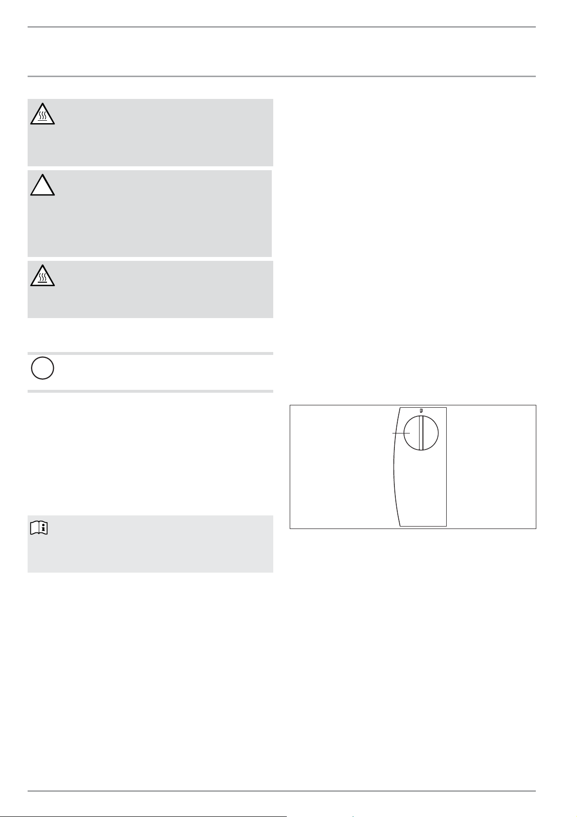
1
26_07_31_0211
1 Temperature selector
5.1 Starting heating
The temperature is infi nitely adjustable. The appliance stops heating as soon as the selected room temperature has been reached.
Turn the temperature selector clockwise to the required
setting.
5.2 Stopping heating / frost protection
Turn the temperature selector fully counter clockwise.
This position ensures frost protection. The heater starts automatically if the room temperature drops below the frost protection
temperature.
IF YOU HAVE ANY QUESTIONS CONCERNING THE REGISTRATION PROCESS OR WARRANTY OPTIONS, PLEASE CONTACT
STIEBEL ELTRON USA DIRECTLY AT (800)-582-8423.
4 | CK 15-20 E / CKT 15-20 E WWW.STIEBEL-ELTRON-USA.COM
Page 5

OPERATION
OPERATION CKT 15 E / CKT 20 E
6. Operation CKT 15 E / CKT 20 E
1
2
1 Temperature selector
2 Timer
6.1 Starting heating
The temperature is infi nitely adjustable. The appliance stops heating as soon as the selected room temperature has been reached.
Turn the temperature selector clockwise to the required
setting.
6.2 Adjusting the time switch
7. Cleaning, care and maintenance
The appliance contains no user serviceable parts.
Clean the appliance when cold with ordinary cleaning products.
Avoid abrasive or corrosive cleaning products.
If a pale brownish discoloration appears on the appliance casing,
wipe this off as soon as possible with a damp cloth.
Damage to the appliance and the environment
!
Never spray cleaning spray into the air slot.
26_07_31_0214
8. Storage
When not in use, keep the appliance in a dry place.
9. Troubleshooting
If the appliance does not heat, check the temperature set at the
appliance and the circuit breacker.
The appliance has a safety high limit that shuts the appliance down
if it overheats. After the cause has been removed (for example air
outlet or inlet apertures covered) and the appliance has cooled
down for a few minutes, operation starts again.
ENGLISH
With the time switch, the appliance heats with full output and
without temperature control.
Turn the Timer clockwise to set any number of minutes to
count down from 0-60minutes.
6.3 Stopping heating / frost protection
This position ensures frost protection. The heater starts automatically if the room temperature drops below the frost protection
temperature.
Turn the temperature selector fully counter clockwise and
ensure that the time switch is set to "0".
If you cannot remedy the fault, notify the contractor who installed
the appliance. To facilitate and speed up your enquiry, please provide the serial number from the type plate (000000-0000-000000).
WWW.STIEBEL-ELTRON-USA.COM CK 15-20 E / CKT 15-20 E| 5
Page 6
INSTALLATION
SAFETY
INSTALLATION
10. Safety
Only licensed electricians should carry out the maintenance and
repair of this appliance.
10.1 General safety information
We guarantee trouble-free operation and operational reliability
only if the original accessories and spare parts intended for the
appliance are used.
10.2 Instructions, standards and regulations
Note
Observe all applicable national and local regulations and
instructions.
11. Appliance description
This appliance is a wall mounted electric heater. It is particularly
suitable for heating rooms, such as work rooms, kitchens, bathrooms, wash rooms etc.
11.1 Standard delivery
- Wall mount bracket
- Bottom bracket
12. Installation
DANGER Electrocution
- If installing the appliance in rooms with a bath and/
or shower, take the relevant safety zone into account in accordance with the information on the appliance type plate.
- Install the appliance in such a way that switching
and control equipment cannot be touched by a person in the bath or shower.
Secure the appliance with the bottom bracket and one screw
against unintentional unhooking. To do so, hook the bottom
bracket from the back into the rear panel.
13. Electrical connection
DANGER Electrocution
Carry out all electrical connection and installation work
in accordance with relevant regulations.
Damage to the appliance and the environment
!
- Observe the type plate. The specifi ed voltage must
match the mains voltage.
Never install the appliance directly below an outlet.
In case of ROMEX wire, install ½" ROMEX connector in knockout.
In case of Greenfi eld, please use ½" Greenfi eld connector.
13.1 Terminal block
We recommend using stranded wire to connect to the terminal
block. Crimp a ferrule over stranded bare wire to ensure a good
connection.
Consult the chart below for the recommended torque amounts on
the terminal block screws.
Screw Diameter (mm) Torque (N•cm) Torque (lbf•in)
2.8 30-40 2.65-3.54
2.8-3 35-50 3.09-4.42
3-3.2 50-60 4.42-5.31
3.2-3.6 60-80 5.31-7.08
3.6-4.1 90-120 7.96-10.6 2
4.1-4.7 120-180 10.62-15.93
4.7-5.3 150-200 13.27-17.7
Using the proper torque specifi cations to secure wire to the wiring
block helps to avoid personal loss or property damage.
See 15.3, “Specifi cation table”, pg. 8 for information on the
proper wire gauge size.
DANGER Fire
- Only fi t the appliance to a vertical wall that is heat-
resistant to at least194°F(90 °C).
- Maintain minimum clearances to adjacent surfaces.
- Never install the appliance directly below a wall
socket.
Check the hole distances for the wall mounting bracket in the
dimensioned drawing.
Secure the wall mounting bracket with suitable fasteners.
The horizontal and vertical slots in the wall mounting bracket
enable alignment if drilled holes are not completely accurate.
Hook in the appliance so that both top protrusions are in-
serted into the slots in the wall mounting bracket.
6 | CK 15-20 E / CKT 15-20 E WWW.STIEBEL-ELTRON-USA.COM
14. Appliance handover
Explain the functions of the appliance to the user. Draw special
attention to the safety information. Hand the operating and installation instructions to the user.
Page 7
INSTALLATION
SPECIFICATION
15. Specifi cation
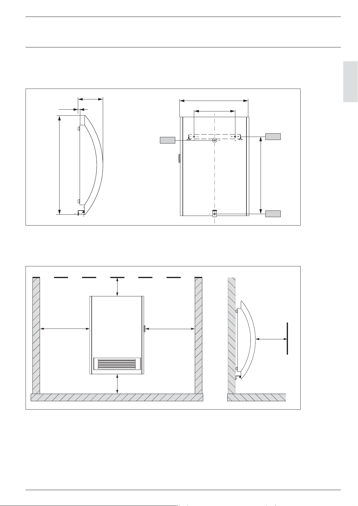
15.1 Dimensions
Ý(12.3 cm)
4Ý(10 cm)
ENGLISH
13òÝ(33.5 cm)
8Ý(20 cm)
18Ý
(46 cm)
1 Wall mounting bracket
2 Cable entry
3 Bottom bracket
15.2 Minimum clearances to hard surfaces
ANY HARD SURFACE
minimum 4Ý(10 cm)
2
1
14óÝ
(36.5 cm)
3
D0000040347_dim
minimum
4Ý(10 cm)
minimum 4Ý(10 cm) recommended 6-8Ý(15-20 cm)
FLOOR FLOOR
minimum
4Ý(10 cm)
minimum
20Ý(50 cm)
The image above shows minimum allowed clearances between the installed appliance and any hard surfaces.
We recommend installing the appliance 6-8˝ off the floor.
D0000040347_min
WWW.STIEBEL-ELTRON-USA.COM CK 15-20 E / CKT 15-20 E| 7
Page 8
INSTALLATION
SPECIFICATION
WARNING Fire
Combustible materials such as furniture, papers, clothes
and curtains must be kept at least 3 feet (0.9 m) from the
heater.
Never place any fl ammable, combustible or insulating
objects or materials, such as laundr y, blankets, magazines,
containers with fl oor polish or gasoline, spray cans or
similar on the appliance or in direct proximity to it.
15.3 Specifi cation table
CK 15 E CK 20 E CKT 15 E CKT 20 E
Part number 074058 074059 230345 230346
Power supply single phase single phase single phase single phase
Voltage 120 V 240 V 208 V 120 V 240 V 208 V
Wattage 1500 W 2000 W 1500 W 1500 W 2000 W 1500 W
Required circuit breaker size 15 A 15 A 15 A 15 A 15 A 15 A
Required wire size 12 AWG 12 AWG 12 AWG 14 AWG 14 AWG 14 AWG
Temperature range 41°F - 86°F / 5°C - 30°C
Frost protection setting 44.6°F / 7°C
Operating noise 49.7 dB(A)
Height 18.1˝ / 46 cm
Width 13.2˝ / 33.5 cm
Depth 13.2˝ / 12.3 cm
Weight 8.0 lb / 4.4 kg
IP rating IP13B
Safety category I
Color Alpine white
PBTP/ASA Polybutylene Phthalate/Acrylonitrile styrene acrylate
PA Polyamide
PC Polycarbonate
PE Polyethylene
PS Polystyrene
Si Silicon
8 | CK 15-20 E / CKT 15-20 E WWW.STIEBEL-ELTRON-USA.COM
Page 9
INSTALLATION
SPECIFICATION
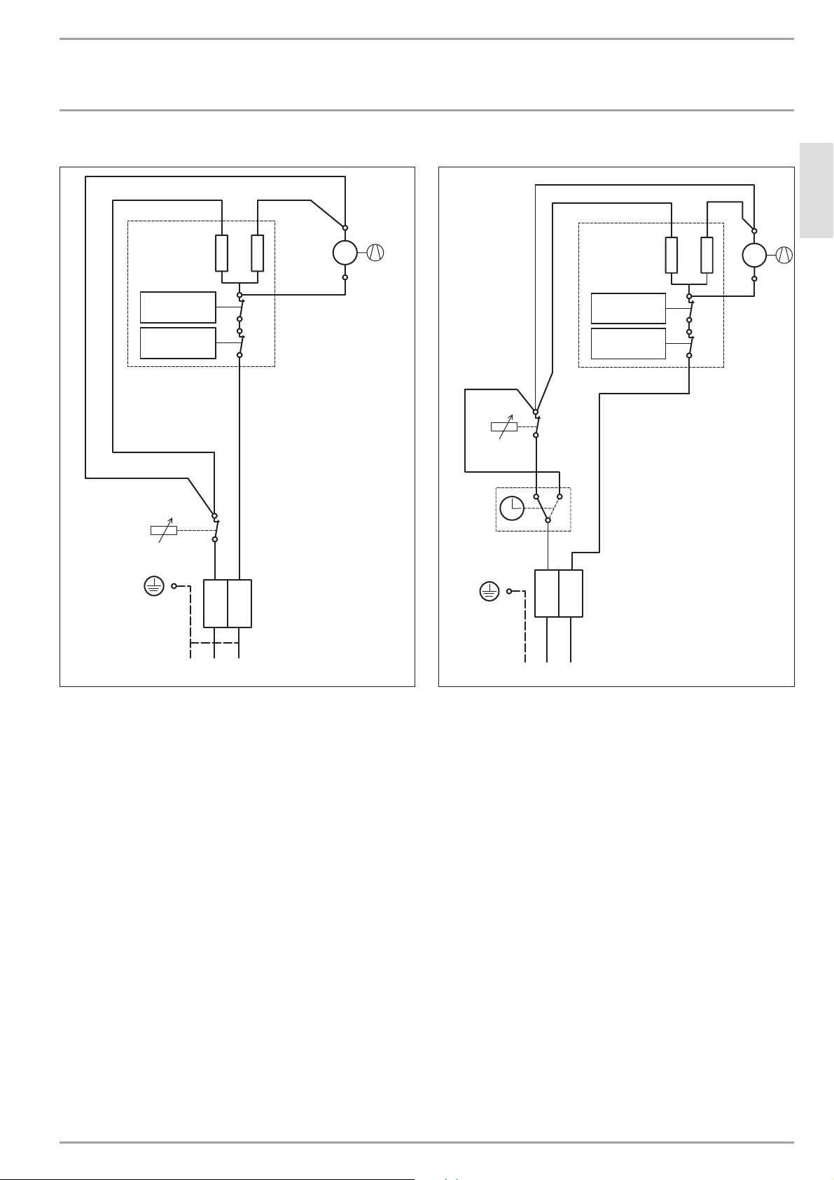
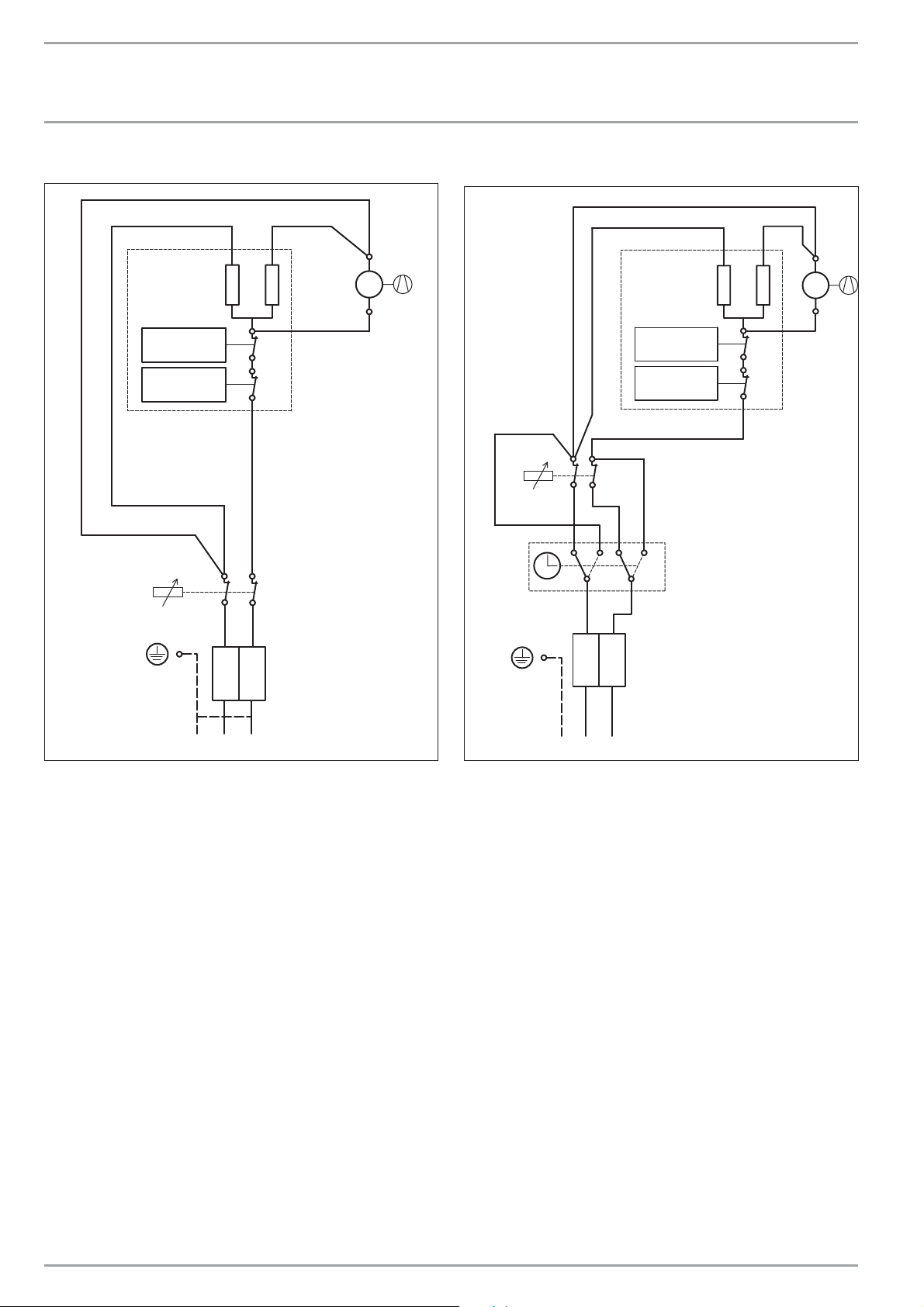
15.4 Wiring diagram CK 15 E
A1
R1 R2
>171°F ± 9°F
-
>80°C ± 5K
>171°F ± 9°F
-
>80°C ± 5K
N1
!
-
15.5 Wiring diagram CKT 15 E
A1
M
1
~
M1
F1
F2
N1
!
-
2
T1
3
1
>171°F ± 9°F
-
>80°C ± 5K
>171°F ± 9°F
-
>80°C ± 5K
R1 R2
F1
F2
M
1
~
M1
ENGLISH
X1
1
2
GRD L1 N
CK 15 E:
A1 Electric heating element assembly
F1 Temperature high Limit
M1 Fan
N1 Thermostat
R1 Heating resistor
R2 Heating resistor
X1 Wiring block
X1
1
2
CK_15_ SP_TS
CKT 15 E:
GRD L1 N
A1 Electric heating element assembly
F1 Temperature high Limit
M1 Fan
N1 Thermostat
R1 Heating resistor
R2 Heating resistor
T1 60 minute timer
X1 Wiring block
CKT_15_SP_TS
WWW.STIEBEL-ELTRON-USA.COM CK 15-20 E / CKT 15-20 E| 9
Page 10
INSTALLATION
SPECIFICATION
15.6 Wiring diagram CK 20 E
A1
R1 R2
>171°F ± 9°F
-
>80°C ± 5K
>171°F ± 9°F
-
>80°C ± 5K
N1
!
-
15.7 Wiring diagram CKT 20 E
A1
M
1
~
M1
>171°F ± 9°F
F1
F2
N1
!
-
2
T1
3
1
-
>80°C ± 5K
>171°F ± 9°F
-
>80°C ± 5K
5
6
4
R1 R2
F1
F2
M
1
~
M1
X1
1
2
GRD L1 L2CK 20 E:
A1 Electric heating element assembly
F1 Temperature high Limit
M1 Fan
N1 Thermostat
R1 Heating resistor
R2 Heating resistor
X1 Wiring block
X1
1
2
CK_20_DP_TS
CKT 20 E:
GRD L1 L2
A1 Electric heating element assembly
F1 Temperature high Limit
M1 Fan
N1 Thermostat
R1 Heating resistor
R2 Heating resistor
T1 60 minute timer
X1 Wiring block
CKT_20_DP_TS
10 | CK 15-20 E / CKT 15-20 E WWW.STIEBEL-ELTRON-USA.COM
Page 11

WARRANTY | ENVIRONMENT AND RECYCLING
16. Warranty
LIMITED WARRANTY
Subject to the terms and conditions set forth in this limited
warranty, Stiebel Eltron, Inc. (the “Manufacturer”) hereby
warrants to the original purchaser (the “Owner”) that
each Electric Space Heater (the “Heater”) shall be free of
defects in the Manufacturer’s materials or workmanship
for a period of three (3) years from the date of purchase.
As Owner’s sole and exclusive remedy for breach of the
above warranty, Manufacturer shall, at the Manufacturer’s
discretion, send replacement parts for local repair; retrieve
the unit for factory repair, or replace the defective Heater
with a replacement unit with comparable operating
features. Manufacturer’s maximum liability under all
circumstances shall be limited to the Owner’s purchase
price for the Heater.
This limited warranty shall be the exclusive warranty
made by the Manufacturer and is made in lieu of all other
warranties, express or implied, whether written or oral,
including, but not limited to warranties of merchantability
and fi tness for a particular purpose. Manufacturer shall
not be liable for incidental, consequential or contingent
damages or expenses arising directly or indirectly from any
defect in the Heater or the use of the Heater. Manufacturer
shall not be liable for any damage to property of Owner
arising, directly or indirectly, from any defect in the Heater
or the use of the Heater. Manufacturer alone is authorized
to make all warranties on Manufacturer’s behalf and no
statement, warranty or guarantee made by any other party
shall be binding on Manufacturer.
Manufacturer shall not be liable for any damage
whatsoever relating to or caused by:
1. any misuse or neglect of the Heater, any accident to
the Heater, any alteration of the Heater, or any other
unintended use;
2. acts of God and circumstances over
which Manufacturer has no control;
3. installation of the Heater other than as directed by
Manufacturer and other than in accordance with
applicable building codes;
4. failure to maintain the Heater or to operate the Heater
in accordance with the Manufacturer’s specifi cations;
5. improper installation and/or improper materials used
by any installer and not relating to defects in parts or
workmanship of Manufacturer;
6. moving the Heater from its original place of installation;
7. use on improper voltage or current;
8. disassembly, repair, or alteration by anyone other than
the manufacturer.
Should owner wish to return the Heater to manufacturer
for repair or replacement under this warranty, Owner
must fi rst secure written authorization from Manufacturer.
Owner shall demonstrate proof of purchase, including a
purchase date, and shall be responsible for all removal
and transportation costs. If Owner cannot demonstrate a
purchase date this warranty shall be limited to the period
beginning from the date of manufacture stamped on the
Heater. Manufacturer reserves the right to deny warranty
coverage upon Manufacturer’s examination of Heater.
This warranty is restricted to the Owner and cannot be
assigned.
Some States and Provinces do not allow the exclusion
or limitation of certain warranties. In such cases, the
limitations set forth herein may not apply to the Owner. In
such cases this warranty shall be limited to the shortest
period and lowest damage amounts allowed by law. This
warranty gives you specifi c legal rights and you may also
have other rights which vary from State to State or Province
to Province.
Owner shall be responsible for all labor and other charges
incurred in the removal or repair of the Heater in the fi eld.
ENGLISH
The installation, electrical connection and first operati-
!
on of this appliance should be carried out by a qualified
installer.
The company does not accept liability for failure of any
!
goods supplied which have not been installed and ope-
rated in accordance with the manufacturer‘s instructions.
Environment and recycling
Please help us to protect the environment by disposing of the
packaging in accordance with the national regulations for waste
processing.
WWW.STIEBEL-ELTRON-USA.COM CK 15-20 E / CKT 15-20 E| 11
This Warranty is valid for U.S.A. & Canada only. Warranties
may vary by country. Please consult your local Stiebel Eltron
Representative for the Warranty for your country.
Page 12

ÍNDICE | OPERACIÓN
INSTRUCCIONES IMPORTANTES
OPERACIÓN
1. INSTRUCCIONES IMPORTANTES ___________________________ 12
1.1 Información del documento __________________________________12
1.2 Indicaciones de seguridad ____________________________________13
1.3 Otras marcas presentes en esta documentación _________ 13
2. Seguridad ___________________________________________________ 13
2.1 Uso previsto ______________________________________________________ 13
2.2 Información de seguridad ____________________________________ 13
2.3 Indicaciones generales ________________________________________ 14
2.4 Sello de certifi cación ___________________________________________ 14
2.5 Autorizaciones ___________________________________________________14
3. Descripción del aparato ___________________________________ 14
3.1 Operación con reguladores externos de temperatura __ 14
4. Operación CK 15 E / CK 20 E _______________________________ 14
4.1 Encender la calefacción _______________________________________ 14
4.2 Desconectar la calefacción / protección antiescarcha __ 14
5. Operación CKT 15 E / CKT 20 E ____________________________ 15
5.1 Encender la calefacción _______________________________________ 15
5.2 Ajustar el temporizador _______________________________________15
5.3 Desconectar la calefacción / protección antiescarcha __15
6. Limpieza, conservación y mantenimiento _______________ 15
7. Almacenaje _________________________________________________ 15
8. Solución de problemas ____________________________________ 15
INSTALACIÓN
9. Seguridad ___________________________________________________ 16
9.1 Indicaciones generales de seguridad _______________________ 16
9.2 Directivas, normas y disposiciones__________________________16
10. Descripción del aparato ___________________________________ 16
10.1 Ámbito de suministro __________________________________________16
11. Montaje _____________________________________________________ 16
12. Conexión eléctrica _________________________________________ 16
12.1 Bloque de terminales __________________________________________16
13. Entrega del aparato a terceras personas ________________ 16
14. Especifi caciones técnicas __________________________________ 17
14.1 Medidas ___________________________________________________________ 17
14.2 Distancias mínimas _____________________________________________17
14.3 Tabla de especifi caciones _____________________________________18
14.4 Plano eléctrico CK 15 E ________________________________________ 19
14.5 Plano eléctrico CKT 15 E _______________________________________ 19
14.6 Plano eléctrico CK 20 E ________________________________________ 20
14.7 Plano eléctrico CKT 20 E _______________________________________20
15. Garantía _____________________________________________________ 21
OPERACIÓN
1. INSTRUCCIONES IMPORTANTES
GUARDE ESTAS INSTRUCCIONES
Siempre que se utilizan artefactos eléctricos, se deben tomar
precauciones básicas para reducir los riesgos de incendio, shock
eléctrico y lesiones personales, incluyendo las siguientes:
1. Lea todas las instrucciones antes de instalar o utilizar el calefactor.
2. El calefactor se calienta cuando está funcionando. Para prevenir
quemaduras, evite que la piel desnuda entre en contacto con las
superfi cies calientes. Mantenga materiales combustibles, tales
como muebles, almohadas, ropa de cama, papeles, ropa, etc.
y cortinas a una distancia de al menos 1 m (3 ft) del frente del
calefactor, y a una distancia de al menos 1 m (3 ft) de los laterales
y la parte posterior del artefacto.
3. Se deben tomar precauciones extremas cuando cualquier calefactor es utilizado por o cerca de niños o personas discapacitadas
y cuando el calefactor se deja funcionando y sin vigilancia.
4. No utilice ningún calefac tor que haya tenido un funcionamiento
defectuoso. Desconecte la energía del panel de servicio y haga que
un electricista confi able lo revise antes de reutilizarlo.
1.1 Información del documento
El capítulo Operación está destinado a usuarios y técnicos en calefacción.
El capítulo Instalación está destinado a técnicos en calefacción.
Indicación
Lea las instrucciones cuidadosamente antes de utilizar
el artefacto y guárdelas para consultas futuras. Pásele
las instrucciones a cualquier nuevo usuario.
12 | CK 15-20 E / CKT 15-20 E WWW.STIEBEL-ELTRON-USA.COM
Page 13

OPERACIÓN
SEGURIDAD
1.2 Indicaciones de seguridad
1.2.1 Estructura de las instrucciones de seguridad
ADVERTENCIA Tipo de peligro
A continuación se indican algunas de las posibles
consecuencias ante el desobedecimiento de las instrucciones de seguridad.
A continuación se proporcionan medidas para
evitar el peligro.
1.2.2 Símbolos, tipo de peligro
Símbolo Tipo de peligro
Lesión
!
Electrocución
Quemadura o escaldamiento
Incendio
1.2.3 Palabras de advertencia
PALABRA DE
ADVERTENCIA
PELIGRO Indicaciones, que en caso de no considerarlas, tiene como
ADVERTENCIA Indicaciones, que en caso de no considerarlas, puede tener
PRECAUCIÓN Indicaciones, que en caso de no considerarlas, puede tener
Significado
consecuencia lesiones graves o la muerte.
como consecuencia lesiones graves o la muerte.
como consecuencia lesiones de gravedad media o baja.
1.3 Otras marcas presentes en esta documentación
Indicación
Las indicaciones están delimitadas por líneas horizontales sobre y debajo del mensaje de texto. Las indicaciones
generales se señalizan mediante el símbolo adyacente.
Lea atentamente las indicaciones.
Símbolo
Daños a aparatos y daños medioambientales
!
Eliminación del aparato
2. Seguridad
Observe las siguientes indicaciones de seguridad y prescripciones.
El equipo sólo debe utilizarse después de haber sido instalado
completamente y con todos los dispositivos de seguridad.
2.1 Uso previsto
Este artefacto está diseñado para calefaccionar espacios en viviendas.
Cualquier otro uso diferente del descripto será considerado inapropiado. El cumplimiento de estas instrucciones es también parte
del uso correcto de este artefacto. Cualquier modifi cación o transformación del artefacto invalida todos los derechos de garantía.
2.2 Información de seguridad
PELIGRO Electrocución
- Antes de la limpieza, asegúrese de que la corriente
esté desconectada en el panel del interruptor y de
que el elemento de calentamiento del calentador
esté frío.
PELIGRO Incendio
No ponga en funcionamiento el aparato ...
- si no se respetan las distancias mínimas con res-
pecto a otros objetos limítrofes como, por ejemplo,
muebles, cortinas y otros textiles o materiales infl amables (las distancias mínimas fi guran en el capítulo "Especifi caciones técnicas/medidas y distancias
mínimas").
- si las habitaciones corren peligro de incendio o de
explosión debido a la presencia de sustancias químicas, gases o vapores.
- si se encuentra colocado cerca de tuberías o depó-
sitos que contienen o conducen sustancias infl amables o explosivas.
- si en la habitación de colocación se están realizando
trabajos de instalación, mecanizado o sellado.
- si se manipulan sprays de gasolina, encáusticos o
productos similares ventile sufi cientemente la habitación antes de calentar.
- si un componente del aparato presenta daños, si el
aparato ha caído o si existió anteriormente un mal
funcionamiento.
- al aire libre.
PELIGRO Incendio
Sobre el aparato o cerca de él no se pueden depositar
objetos combustibles, infl amables o aislantes térmicos,
tales como piezas de ropa, mantas, periódicos, depósitos
con encáusticos o gasolina, botes de spray o similares.
ADVERTENCIA Incendio
Asegúrese de que en las aberturas de entrada y salida
de aire no entren cuerpos extraños, ya que esto podría
causar una descarga eléctrica, un incendio o daños en
el aparato.
ESPAÑOL
No tape el equipo
Este símbolo indica que Usted tiene que realizar una acción.
Las acciones necesarias se describen paso a paso.
WWW.STIEBEL-ELTRON-USA.COM CK 15-20 E / CKT 15-20 E | 13
Page 14

OPERACIÓN
DESCRIPCIÓN DEL APARATO
ADVERTENCIA Incendio
Para evitar incendios, asegúrese de no bloquear las
aberturas de entrada y salida de aire. No utilice el aparato nunca sobre superfi cies blandas, como por ejemplo sobre una cama, ya que esto podría bloquear las
aberturas.
PELIGRO Sobrecalentamiento
Al utilizar un temporizador para el funcionamiento,
puede que el aparato siga calentando la habitación sin
regulación. Si la habitación es pequeña y las personas
que se encuentran en ella no pueden abandonarla de
forma independiente, garantice una vigilancia permanente.
ADVERTENCIA Peligro de lesiones
!
Si niños o personas con discapacidad física, sensorial o
mental, manipulan el aparato, debe asegurarse de que
esto solamente se realice bajo vigilancia o después de
haber recibido la instrucción adecuada por una persona
que esté a cargo de su seguridad.
Los niños deben permanecer vigilados en todo momento
para asegurarse de que no juegan con el aparato.
CUIDADO Quemaduras
Las superfi cies de la carcasa del equipo y el aire que sale
de éste se calientan mucho durante el funcionamiento
(más de 90 °C (194 °F)). Para evitar quemaduras, procure que la piel no entre en contacto con las superfi cies
calientes.
3. Descripción del aparato
El aparato va fi jado a la pared y sobre todo es adecuado para
cuartos de trabajo, cocinas, lavabos y habitaciones semejantes.
La carcasa del aparato es de acero esmaltado al horno. Ambos
lados están limitados por dos piezas laterales de plástico. En el
lateral derecho se encuentran los elementos de mando.
El ventilador silencioso aspira el aire de la habitación que, después
de ser calentado por el calefactor de resistencias, fl uye a través
del canal de aire caliente para ser expulsado de forma equilibrada
por la rejilla de salida de aire caliente.
El aparato calienta la temperatura ambiente y la mantiene constante a la temperatura ajustada.
3.1 Operación con reguladores externos de temperatura
(Solo válido para: CK)
En habitaciones superiores a 215 ft2 (20 m2) se puede utilizar el
aparato con un regulador externo de temperatura corriente.
Para ello gire el selector de temperatura del aparato hasta el
tope derecho.
4. Operación CK 15 E / CK 20 E
2.3 Indicaciones generales
Daños a aparatos y daños medioambientales
!
- No cubra el aparato.
- No se suba al aparato.
2.4 Sello de certifi cación
Véase placa de especifi caciones en el aparato.
2.5 Autorizaciones
-ETL (EE.UU.)
-C-ETL (Canadá)
1
26_07_31_0211
1 Selector de temperatura
4.1 Encender la calefacción
La temperatura puede ser ajustada sin escalonamientos. El aparato se desconecta en el momento de alcanzarse la temperatura
ajustada.
Gire el selector de temperatura hacia la derecha hasta alcan-
zar la temperatura deseada.
4.2 Desconectar la calefacción / protección antiescarcha
Gire el selector de temperatura del aparato hasta el tope
izquierdo.
En esta posición está activada la protección antiescarcha. La calefacción se enciende automáticamente si la temperatura ambiente
desciende por debajo de la temperatura de protección antiescarcha.
14 | CK 15-20 E / CKT 15-20 E WWW.STIEBEL-ELTRON-USA.COM
Page 15

OPERACIÓN
OPERACIÓN CKT 15 E / CKT 20 E
5. Operación CKT 15 E / CKT 20 E
1
2
1 Selector de temperatura
2 Temporizador
5.1 Encender la calefacción
La temperatura puede ser ajustada sin escalonamientos. El aparato se desconecta en el momento de alcanzarse la temperatura
ajustada.
Gire el selector de temperatura hacia la derecha hasta alcan-
zar la temperatura deseada.
5.2 Ajustar el temporizador
Con temporizador, el aparato calienta a plena potencia sin regulación de temperatura.
Gire el selector del temporizador hacia la derecha para ajus-
tar el tiempo de funcionamiento deseado de 0 - 60 minutos.
6. Limpieza, conservación y mantenimiento
El aparato no contiene ningún componente que necesite un mantenimiento por parte del usuario.
Limpie el aparato en estado frío utilizando productos de limpieza
corrientes. Evite utilizar limpiadores agresivos o corrosivos.
Si se producen decoloraciones leves amarronadas en la carcasa
del equipo, límpielas de inmediato frotando con un trapo humedecido.
26_07_31_0214
Daños a aparatos y daños medioambientales
!
No rocíe spray limpiador en las ranuras de ventilación
de aire.
7. Almacenaje
Cuando el aparato esté fuera de uso, guárdelo en un lugar
seco.
8. Solución de problemas
Si el aparato no calienta, revise la temperatura ajustada en el
aparato y el fusible de la instalación doméstica.
El aparato dispone de un regulador de temperatura de seguridad
que se desconecta si el aparato se sobrecalienta. Tras reparar
la causa (p.ej. abertura de salida o de entrada de aire cubierta),
el aparato volverá a ponerse en marcha en unos pocos minutos
después de un intervalo de tiempo de enfriado.
ESPAÑOL
5.3 Desconectar la calefacción / protección antiescarcha
En esta posición está activada la protección antiescarcha. La calefacción se enciende automáticamente si la temperatura ambiente
baja por debajo de la temperatura de protección antiescarcha.
Gire el selector de temperatura del aparato hasta el tope iz-
quierdo y cerciórese que el temporizador está ajustado a "0".
Si no puede solucionar la causa, llame al instalador. Para poder
ayudarle mejor y con mayor agilidad, indique el número de la
placa de modelo (000000-0000-000000).
WWW.STIEBEL-ELTRON-USA.COM CK 15-20 E / CKT 15-20 E | 15
Page 16

OPERACIÓN
SEGURIDAD
INSTALACIÓN
9. Seguridad
El mantenimiento y la reparación del aparato sólo puede ser realizado por un técnico del servicio postventa.
9.1 Indicaciones generales de seguridad
Sólo garantizamos una funcionalidad y seguridad de funcionamiento perfectas si se utilizan accesorios y piezas de repuesto
originales previstos para el aparato.
9.2 Directivas, normas y disposiciones
Indicación
Tenga presentes todos los reglamentos y disposiciones
nacionales y regionales.
10. Descripción del aparato
El equipo es un aparato eléctrico de calefacción directa, que es
fi jado a la pared. El aparato es muy apto para calentar habitaciones como p. ej. cuartos de trabajo, cocinas, baños, lavabos etc.
10.1 Ámbito de suministro
- Soporte de pared
- Ángulo de fi jación
11. Montaje
PELIGRO Electrocución
- En caso de instalar el aparato en habitaciones con
bañera y/o ducha, tenga en cuenta el área de protección en concordancia con las indicaciones en la
placa de especifi caciones del aparato.
- Coloque el aparato de forma que los dispositivos de
conmutación y regulación no puedan entrar en contacto con la persona que se encuentre en la bañera
o bajo la ducha.
PELIGRO Incendio
- El aparato solo puede ser colocado a una pared
vertical y resistente a temperaturas de 90 °C como
mínimo.
- Mantenga las distancias mínimas respecto a las su-
perfi cies de los objetos colindantes.
- No puede colocar el aparato inmediatamente debajo
de una toma de corriente de pared.
Coloque el ángulo de fi jación y el tornillo para asegurar
que el aparato no sea descolgado involuntariamente. Cuelgue para ello el ángulo de fi jación desde atrás en la pared
trasera.
12. Conexión eléctrica
PELIGRO Electrocución
Realice los trabajos de conexión e instalación eléctricos
conforme a la normativa vigente.
Daños a aparatos y daños medioambientales
!
Observe la placa de especifi caciones. La tensión indicada
debe coincidir con la tensión eléctrica disponible.
No coloque el aparato inmediatamente debajo de una toma de
corriente de pared.
En caso de cable ROMEX , instale ½" ROMEX conector. En caso de
Greenfi eld, utilice por favor ½" Greenfi eld conector.
12.1 Bloque de terminales
Se recomienda usar cable trenzado para conectar al bloque de
terminales. Engarce una férula sobre cable trenzado pelado para
asegurar una buena conexión.
Consulte el siguiente diagrama para ver el nivel recomendado de
torsión en los tornillos del bloque de terminales.
Diámetro del cable (mm) Torsión (N•cm) Torsió n
(lbf•in)
2.8 30-40 2.65-3.54
2.8-3 35-50 3.09-4.42
3-3.2 50-60 4.42-5.31
3.2-3.6 60-80 5.31-7.08
3.6-4.1 90-120 7.96-10.6 2
4.1-4.7 120-180 10.62-15.93
4.7-5.3 150-200 13.27-17.7
Usar las especifi caciones de torsión adecuadas para fi jar el cable
al bloque de cableado ayuda a evitar pérdidas personales o daños
a la propiedad.
Consulte las tablas de la sección 14.3, pág. 18 para ver información sobre el calibre adecuado para los cables.
13. Entrega del aparato a terceras personas
Explique al usuario las funciones del equipo. Subraye la importancia de las instrucciones de seguridad indicándoselas. Entregue
al usuario el manual de operación e instalación.
Observe en el plano dimensional la distancia entre los aguje-
ros para el monaje del soporte de pared.
Fije el soporte de pared con material de fi jación adecuado.
Con los oblongos horizontales y verticales se posibilita un
mejor ajuste del soporte de pared respecto a los taladros.
Cuelgue el aparato de manera que los dos anclajes situados
en la parte superior de la pared trasera entren en las ranuras del soporte de pared.
16 | CK 15-20 E / CKT 15-20 E WWW.STIEBEL-ELTRON-USA.COM
Page 17

INSTALACIÓN
ESPECIFICACIONES TÉCNICAS
14. Especifi caciones técnicas
14.1 Medidas
Ý(12.3 cm)
4Ý(10 cm)
18Ý
(46 cm)
1 Soporte de pared
2 Paso de cables eléctricos
3 Ángulo de fi jación
14.2 Distancias mínimas
13òÝ(33.5 cm)
8Ý(20 cm)
2
1
14óÝ
(36.5 cm)
ESPAÑOL
3
D0000040347_dim
CUALQUIER SUPERFICIE DURA
mínimo 4Ý(10 cm)
mínimo
4Ý(10 cm)
mínimo 4Ý(10 cm) recomendado 6-8Ý(15-20 cm)
SUELO SUELO
mínimo
4Ý(10 cm)
mínimo
20Ý(50 cm)
La imagen de arriba muestra las distancias mínimas permitidas entre el aparato instalado y cualquier superfi cies dura.
Recomendamos que se instale el aparato a 6-8” del suelo.
D0000040347_min_es
WWW.STIEBEL-ELTRON-USA.COM CK 15-20 E / CKT 15-20 E | 17
Page 18

INSTALACIÓN
ESPECIFICACIONES TÉCNICAS
PELIGRO Incendio
Los materiales combustibles como muebles, papeles,
ropa y cortinas deben mantenerse al menos a 3 pies (0,9
m) del calentador.
Nunca coloque objetos o materiales inflamables,
combustibles o aislantes, como ropa lavada, sábanas,
revistas, recipientes con cera para pisos o gasolina,
aerosoles u objetos similares sobre el artefacto o en
cercanía directa a él.
14.3 Tabla de especifi caciones
CK 15 E CK 20 E CKT 15 E CKT 20 E
Número de pedido 074058 074059 230345 230346
Conexión eléctrica monofásico monofásico monofásico monofásico
Voltaje 120 V 240 V 208 V 120 V 240 V 208 V
Vatios 1500 W 2000 W 1500 W 1500 W 2000 W 1500 W
Interruptor auto. # requerido 15 A 15 A 15 A 15 A 15 A 15 A
Calibre de alambre 12 AWG 12 AWG 12 AWG 14 AWG 14 AWG 14 AWG
Rango de ajuste 41°F - 86°F / 5°C - 30°C
Posición de protección antiescarcha 44.6°F / 7°C
Ruido de funcionamiento 49.7 dB(A)
Altura 18.1˝ / 46 cm
Ancho 13.2˝ / 33.5 cm
Profundidad 13.2˝ / 12.3 cm
Peso 8.0 lb / 4.4 kg
Tipo de protección (IP) IP13B
Clase de protección I
Color Alpine white
18 | CK 15-20 E / CKT 15-20 E WWW.STIEBEL-ELTRON-USA.COM
Page 19

INSTALACIÓN
ESPECIFICACIONES TÉCNICAS
14.4 Plano eléctrico CK 15 E
A1
R1 R2
>171°F ± 9°F
-
>80°C ± 5K
>171°F ± 9°F
-
>80°C ± 5K
N1
!
-
14.5 Plano eléctrico CKT 15 E
A1
M
1
~
M1
F1
F2
N1
!
-
2
T1
3
1
>171°F ± 9°F
-
>80°C ± 5K
>171°F ± 9°F
-
>80°C ± 5K
R1 R2
F1
F2
M
1
~
M1
ESPAÑOL
X1
1
2
GRD L1 N
CK 15 E:
A1 Grupo constructivo cuerpo calefactor eléctrico
F1 Protección sobrecalentamiento
M1 Ventilador
N1 Regulador de temperatura
R1 Resistencia calefactora
R2 Resistencia calefactora
X1 Conexión bipolar
X1
1
2
CK_15_ SP_TS
CKT 15 E:
GRD L1 N
A1 Grupo constructivo cuerpo calefactor eléctrico
F1 Protección sobrecalentamiento
M1 Ventilador
N1 Regulador de temperatura
R1 Resistencia calefactora
R2 Resistencia calefactora
T1 Temporizador corto 60 min
X1 Regleta de conexiones bipolar
CKT_15_SP_TS
WWW.STIEBEL-ELTRON-USA.COM CK 15-20 E / CKT 15-20 E | 19
Page 20

INSTALACIÓN
ESPECIFICACIONES TÉCNICAS
14.6 Plano eléctrico CK 20 E
A1
R1 R2
>171°F ± 9°F
-
>80°C ± 5K
>171°F ± 9°F
-
>80°C ± 5K
N1
!
-
14.7 Plano eléctrico CKT 20 E
A1
M
1
~
M1
>171°F ± 9°F
F1
F2
N1
!
-
2
T1
3
1
-
>80°C ± 5K
>171°F ± 9°F
-
>80°C ± 5K
5
6
4
R1 R2
F1
F2
M
1
~
M1
X1
1
2
GRD L1 L2CK 20 E:
A1 Grupo constructivo cuerpo calefactor eléctrico
F1 Protección sobrecalentamiento
M1 Ventilador
N1 Regulador de temperatura
R1 Resistencia calefactora
R2 Resistencia calefactora
X1 Conexión bipolar
X1
1
2
CK_20_DP_TS
CKT 20 E:
GRD L1 L2
A1 Grupo constructivo cuerpo calefactor eléctrico
F1 Protección sobrecalentamiento
M1 Ventilador
N1 Regulador de temperatura
R1 Resistencia calefactora
R2 Resistencia calefactora
T1 Temporizador corto 60 min
X1 Regleta de conexiones bipolar
CKT_20_DP_TS
20 | CK 15-20 E / CKT 15-20 E WWW.STIEBEL-ELTRON-USA.COM
Page 21

GARANTÍA | MEDIO AMBIENTE Y RECICLAJE
15. Garantía
GARANTÍA LIMITADA
Sujeto a los términos y condiciones expresados en esta
garantía limitada, Stiebel Eltron, Inc. (el “Fabricante”)
por la presente asegura al comprador original (el
“Propietario”) que cada calentador eléctrico de ambiente
(el “Calentador”) estará libre de defectos en los materiales
del Fabricante o la mano de obra durante un período de
tres (3) años a partir de la fecha de compra. Como única y
exclusiva solución para el Propietario por incumplimiento
de la presente garantía, el Fabricante, a discreción del
Fabricante, enviará repuestos para reparación local,
recuperará la unidad para su reparación en fábrica o
reemplazará el Calentador defectuoso con una unidad de
reemplazo que tenga características de funcionamiento
comparables. La máxima responsabilidad del Fabricante en
cualquier circunstancia se limitará al precio de compra del
Calentador que pagó el Propietario.
Esta garantía limitada será la única garantía que ofrece
el Fabricante y reemplaza a todas las demás garantías,
expresas o implícitas, escritas u orales oral, incluidas pero
no limitadas las garantías de comerciabilidad y aptitud
para determinado fi n. El Fabricante no será responsable
de daños incidentales, consecuentes o contingentes o
gastos que surjan directa o indirectamente de cualquier
defecto del Calentador o el uso de este. El Fabricante no
será responsable de cualquier daño a la propiedad del
Propietario que surja directa o indirectamente de cualquier
defecto del Calentador o el uso de este. Solo el Fabricante
está autorizado a ofrecer todas las garantías de parte
del Fabricante y ninguna afi rmación, garantía o promesa
realizada por cualquier otra parte será vinculante para el
Fabricante.
El Fabricante no será responsable por daños de ningún
tipo relacionados u ocasionados por:
1. cualquier uso indebido o falta de cuidado del
Calentador, cualquier accidente que afecte al
Calentador, cualquier alteración del Calentador o
cualquier otro uso incorrecto;
2. casos fortuitos o circunstancias sobre las cuales el
Fabricante no tiene control;
3. instalación del del Calentador que se desvíe de las
directivas del Fabricante y no observe los códigos de
construcción pertinentes;
4. falta de mantenimiento del Calentador o
funcionamiento del Calentador que no sea conforme a
las especifi caciones del Fabricante;
5. instalación defectuosa y/o uso de materiales
inapropiados por parte de cualquier instalador y que no
se relacionen con defectos en los repuestos o la mano
de obra del Fabricante;
6. cambio del Calentador de su lugar original de
instalación;
7. funcionamiento en un voltaje o corriente inapropiada;
8. desarmado, reparación o alteración por cualquier
persona que no sea el Fabricante.
Si el Propietario desea devolver el Calentador al Fabricante
para su reparación o reemplazo bajo los términos de
esta garantía, el Propietario debe obtener primero la
autorización por escrito del Fabricante. El Propietario
deberá presentar una prueba de compra que incluya la
fecha de compra, y será responsable de todos los costos
de desinstalación y transporte. Si el Propietario no puede
demostrar la fecha de compra, esta garantía se limitará
al período que corre a partir de la fecha de fabricación
impresa en el Calentador. El Fabricante se reserva el
derecho de negar la cobertura de esta garantía después
de examinar el Calentador. Esta garantía se limita al
Propietario y no puede transferirse.
Algunos estados y provincias no permiten la exclusión
o limitación de ciertas garantías. En tales casos, las
limitaciones aquí expresadas pueden no aplicarse al
Propietario. En tales casos, esta garantía se limitará al
período más corto y a los importes por daños más cortos
permitidos por ley. Esta garantía le otorga derechos legales
específi cos y puede que usted tenga otros derechos, que
varían de estado y de provincia a provincia.
El Propietario será responsable de todos los costos de
mano de obra y otros cargos incurridos al retirar o reparar
el Calentador en su domicilio.
ESPAÑOL
La instalación, conexión eléctrica y primera
!
operación de este artefacto debe ser realizada
por un instalador calificado.
La compañía no acepta responsabilidad alguna por
!
la falla de cualquier artículo suministrado que no
haya sido instalado y operado de acuerdo con las
instrucciones del fabricante.
Medioambiente y reciclaje
Por favor ayúdenos a proteger el medioambiente eliminando el
embalaje en concordancia con la normativa nacional para el
tratamiento de residuos.
WWW.STIEBEL-ELTRON-USA.COM CK 15-20 E / CKT 15-20 E | 21
Esta Garantía solo es válida en Estados Unidos y Canadá.
Las garantías pueden variar de un país a otro. Consulte a su
representante de Stiebel Eltron local para conocer la Garantía
correspondiente a su país.
Page 22

TABLE DES MATIÈRES | UTILISATION
DIRECTIVES IMPORTANTES
UTILISATION
1. DIRECTIVES IMPORTANTES ________________________________ 22
1.1 Consignes de sécurité __________________________________________ 23
1.2 Autres repérages utilisés dans cette documentation ____23
2. Sécurité _____________________________________________________ 23
2.1 Utilisation conforme ___________________________________________ 23
2.2 Consignes de sécurité générales ____________________________23
2.3 Remarques générales __________________________________________ 24
2.4 Label de conformité ____________________________________________ 24
2.5 Homologation ___________________________________________________ 24
3. Description de l'appareil __________________________________ 24
3.1 Utilisation avec un régulateur externe de température
ambiante _________________________________________________________ 24
4. Utilisation CK 15 E / CK 20 E _______________________________ 25
4.1 Mise en marche du chauffage ________________________________ 25
4.2 Arrêt du chauffage/protection hors gel___________________25
5. Utilisation CKT 15 E / CKT 20 E ____________________________ 25
5.1 Mise en marche du chauffage ________________________________ 25
5.2 Réglage de l'horloge de temporisation ____________________ 25
5.3 Arrêt du chauffage/protection hors gel___________________ 25
6. Nettoyage, entretien et maintenance ____________________ 25
7. Stockage_____________________________________________________ 25
8. Comment remédier à un problème _______________________ 25
INSTALLATION
9. Sécurité _____________________________________________________ 26
9.1 Consignes de sécurité générales ____________________________26
9.2 Prescriptions, normes et directives _________________________ 26
10. Description de l'appareil __________________________________ 26
10.1 Fourniture ________________________________________________________26
11. Montage _____________________________________________________ 26
12. Raccordement électrique __________________________________ 26
12.1 Bloc de câblage _________________________________________________26
13. Remise de l'appareil _______________________________________ 27
14. Données techniques _______________________________________ 28
14.1 Dimensions _______________________________________________________28
14.2 Distances minimales ___________________________________________28
14.3 Tableau de données ____________________________________________ 29
14.4 Schéma de câblage CK 15 E ___________________________________ 30
14.5 Schéma de câblage CKT 15 E _________________________________30
14.6 Garantie Schéma de câblage CK 20 E _______________________ 31
14.7 Schéma de câblage CKT 20 E _________________________________31
15. Garantie _____________________________________________________ 32
UTILISATION
1. DIRECTIVES IMPORTANTES
GARDER CES DIRECTIVES POUR
RÉFÉRENCE ULTÉRIEURE.
Pour réduire le risque d’incendie, de choc électrique ou de blessures, respectez les directives suivantes lorsque vous utilisez des
appareils électriques :
1. Lire toutes les instructions avant d’installer ou d’utiliser cet
appareil de chauffage.
2. Cet appareil est chaud lorsqu’il est en marche. Pour éviter de
vous brûler, ne touchez pas les surfaces chaudes avec la peau
nue. Gardez les matériaux combustibles, comme les meubles, les
coussins, la literie, le papier, les vêtements, etc. et les rideaux à au
moins 1 m (3 pi) de distance du devant de l’appareil de chauffage
et au moins à 1 m (3 pi) de distance latéralement et à l’arrière.
3. Pr enez d e grandes précau tio n lorsque to ut app areil de chauf fage
doit être utilisé en présence ou par des enfants ou des personnes
invalides, ainsi que chaque fois qu’il est laissé en marche sans
surveillance.
4. Ne faites pas fonctionner tout appareil de chauffage qui aurait
mal fonctionné préalablement. Débranchez le cordon électrique à
la prise et faites examiner l’appareil par un électricien de bonne
réputation avant de le réutiliser.
Généralités à propos de ce document
Le chapitre Mode d’emploi est à l’attention des utilisateurs et des
entrepreneurs en systèmes de chauffage.
Le chapitre Installation est à l’attention des entrepreneurs en sys-
tèmes de chauffage.
Lisez attentivement ces directives avant d’utiliser
l’appareil puis mettez-les de côté pour référence ultérieure. Transférez ce document à toute personne qui utilisera
l’appareil.
1.1 Consignes de sécurité
1.1.1 Structure des consignes de sécurité
MENTION D'AVERTISSEMENT Nature du danger
Sont indiqués ici les risques éventuellement encourus
en cas de non-respect de la consigne de sécurité.
Sont indiqués ici les mesures permettant de pal-
lier au danger.
22 | CK 15-20 E / CKT 15-20 E WWW.STIEBEL-ELTRON-USA.COM
Page 23

UTILISATION
SÉCURITÉ
1.1.2 Symboles, nature du danger
Symbole Nature du danger
Blessure
!
Électrocution
Brûlure
Incendie
1.1.3 Mentions d'avertissement
MENTION
D'AVERTISSEMENT
DANGER Caractérise des remarques dont le non-respect entraîne de
AVERTISSEMENT Caractérise des remarques dont le non-respect peut
ATTENTION Caractérise des remarques dont le non-respect peut en-
1.2 Autres repérages utilisés dans cette documentation
Remarque
Les remarques sont délimitées par des lignes horizontales
au-dessus et en dessous du texte. Le symbole ci-contre
caractérise des remarques générales.
Symbole
!
Signification
graves lésions, voire la mort.
entraîner de graves lésions, voire la mort.
traîner des lésions légères ou moyennement graves.
Lisez attentivement les textes de remarque.
Endommagements de l'appareil et pollution de l'environnement
Recyclage de l'appareil
Ne pas couvrir l'appareil
2.1 Utilisation conforme
Cet appareil est conçu pour le chauffage de locaux.
Tout emploi sortant de ce cadre est considéré comme non
conforme.
2.2 Consignes de sécurité générales
DANGER d’électrocution
- Coupez l’alimentation électrique de l’appareil au
disjoncteur avant de le nettoyer et attendez que
l’élément chauffant soit refroidi.
DANGER Incendie
N'utilisez pas l'appareil ...
- lorsque les distances minimales avec les surfaces
des objets voisins (mobilier, rideaux et voilages,
autres textiles ou tout autre matériau infl ammable)
ne sont pas respectées (voir le chapitre Données
techniques / Cotes et distances minimales).
- dans les locaux où existe un risque d'incendie ou
d'explosion en raison de la présence de produits
chimiques, poussières, gaz ou vapeurs.
- à proximité immédiate de câbles ou récipients sus-
ceptibles de contenir ou de transporter des matériaux infl ammables ou explosibles.
- si des travaux de pose, de ponçage, de vitrifi cation
sont exécutés dans le local où l'appareil est installé.
- là où sont manipulés de l'essence, des bombes
aérosols, de l'encaustique ou d'autres produits
identiques. Aérer suffi samment le local avant de
chauffer.
- après une chute de l'appareil, après un fonctionne-
ment défaillant, si un composant de l'appareil est
endommagé.
- à l’extérieur.
DANGER Incendie
Ne posez pas sur l'appareil ou à proximité immédiate
de celui-ci des objets ou des matériaux combustibles,
infl ammables ou isolants thermiques tels que linge, couvertures, journaux, récipients contenant de l'encaustique
ou de l'essence, bombes aérosols et autres produits similaires.
AVERTISSEMENT Incendie
Veillez à ce qu'aucun corps étranger ne pénètre dans les
ouvertures d'entrée ou de sortie d'air. Toute pénétration
d'un corps étranger dans ces ouvertures risque de provoquer une électrocution ou un incendie, ou d'endommager
l'appareil.
FRANÇAIS
AVERTISSEMENT Incendie
Ce symbole vous indique que vous devez agir. Les actions
nécessaires sont décrites étape par étape.
Pour éviter tout incendie, veillez à ne jamais bloquer les
ouvertures d'entrée et de sortie d'air. N'utilisez jamais
l'appareil sur une surface de pose molle (lit par ex.) afi n
d’éviter d’obstruer les ouvertures.
2. Sécurité
Respectez les consignes de sécurité et les prescriptions énoncées
par la suite.
N'utilisez cet appareil que s'il est complètement installé et doté
de tous les dispositifs de sécurité.
WWW.STIEBEL-ELTRON-USA.COM CK 15-20 E / CKT 15-20 E | 23
DANGER Surchauffe
Si l'appareil est utilisé avec une horloge de temporisation, il peut, sans régulation, ne pas cesser de chauffer
le local. Si le local est petit et que les personnes qui
s'y trouvent ne peuvent pas le quitter d'elles-mêmes, il
convient d'assurer une surveillance permanente.
Page 24

UTILISATION
DESCRIPTION DE L'APPAREIL
AVERTISSEMENT Blessure
!
À moins d'être supervisées ou d'avoir reçu les instructions d'usage de la personne responsable de leur sécurité, les personnes (y compris les enfants) aux capacités
physiques, sensorielles ou mentales réduites ne doivent
pas utiliser cet appareil.
Surveillez les enfants pour vous assurer qu'ils ne jouent
pas avec l'appareil.
ATTENTION Brûlures
Les surfaces de l'appareil et l'air rejeté sont chauds
lorsque l'appareil est en service (plus de 90 °C (194 °F)).
Pour éviter des brûlures, évitez tout contact direct de la
peau nue avec les surfaces chaudes.
2.3 Remarques générales
Endommagements de l'appareil et pollution de l'envi-
!
ronnement
- Ne pas couvrez pas l'appareil.
- Ne montez pas sur l'appareil.
2.4 Label de conformité
Voir la plaque signalétique sur l'appareil.
4. Utilisation CK 15 E / CK 20 E
1
26_07_31_0211
1 Sélecteur de température
4.1 Mise en marche du chauffage
La température se règle en continu. L'appareil se coupe dès que
la température ambiante réglée est atteinte.
Tournez le sélecteur de température de l'appareil vers la
droite jusqu'au niveau souhaité.
4.2 Arrêt du chauffage/protection hors gel
Tournez le sélecteur de température de l'appareil vers la
gauche jusqu'en butée.
2.5 Homologation
-ETL (U.S.A)
-C-ETL (Canada)
3. Description de l'appareil
L'appareil se fi xe au mur et convient en particulier pour les bureaux
ou ateliers, cuisines, salles de bains, laveries et locaux similaires.
L'habillage externe de l'appareil est en tôle métallique thermolaquée. Les deux parois latérales sont en matière synthétique et les
organes de commande sont placés sur le côté droit.
Le ventilateur silencieux capte l'air ambiant qui est ensuite chauffé
par le système de chauffe à fi l nu puis souffl é uniformément par
le conduit d’air chaud et la grille de sortie d’air chaud située endessous.
L'appareil chauffe l'air ambiant à la température réglée et maintient cette température constante.
3.1 Utilisation avec un régulateur externe de température ambiante
(Ne s'applique qu'à CK)
Vous avez la possibilité d'utiliser cet appareil dans les locaux de
plus de 215 ft2 (20 m2) avec un régulateur externe de température
ambiante acheté dans le commerce.
Tournez le sélecteur de température de l'appareil vers la
droite jusqu'en butée.
La protection hors gel est activée en cette position. Le chauffage
se met automatiquement en marche si la température ambiante
est inférieure à la température de protection hors gel.
5. Utilisation CKT 15 E / CKT 20 E
1
2
26_07_31_0214
1 Sélecteur de température
2 Horloge de temporisation
5.1 Mise en marche du chauffage
La température se règle en continu. L'appareil se coupe dès que
la température ambiante réglée est atteinte.
Tournez le sélecteur de température de l'appareil vers la
droite jusqu'au niveau souhaité.
5.2 Réglage de l'horloge de temporisation
Sans régulation et avec l'horloge de temporisation, l’appareil
chauffe à pleine puissance.
Tournez le bouton de l'horloge de temporisation vers la
droite pour régler une durée de fonctionnement comprise
entre 0 et 60 minutes.
24 | CK 15-20 E / CKT 15-20 E WWW.STIEBEL-ELTRON-USA.COM
Page 25

UTILISATION
NETTOYAGE, ENTRETIEN ET MAINTENANCE
5.3 Arrêt du chauffage/protection hors gel
La protection hors gel est activée en cette position. Le chauffage
se met automatiquement en marche si la température ambiante
est inférieure à la température de protection hors gel.
Tournez le sélecteur de température de l'appareil vers la
gauche jusqu'en butée et vérifi ez que l'horloge de temporisation est sur 0.
6. Nettoyage, entretien et maintenance
Cet appareil ne contient aucune pièce à entretenir par l'utilisateur.
Nettoyez l'appareil, lorsqu'il est froid, avec des produits d'entretien
usuels. Évitez les produits d'entretien abrasifs et corrosifs.
Si des taches de couleur brune apparaissent sur l'enveloppe de
l'appareil, nettoyez celles-ci avec un chiffon humide le plus tôt
possible.
FRANÇAIS
Endommagements de l'appareil et pollution de l'envi-
!
ronnement
Ne vaporisez pas de nettoyant en spray dans la fente
d'aération.
7. Stockage
Lorsque l'appareil n'est pas utilisé, rangez-le dans un endroit
sec.
8. Comment remédier à un problème
Si l'appareil ne chauffe pas, vérifi ez la température réglée sur
l'appareil et le fusible de l'installation domestique.
L'appareil est équipé d'un thermostat de sécurité qui le coupe en
cas de surchauffe. Une fois la cause éliminée (entrée ou sortie de
l'air recouverte par ex.), l'appareil se remettra en marche après
un temps de refroidissement de quelques minutes.
Appelez un installateur si vous ne réussissez pas à éliminer la
cause. Donnez-lui le numéro indiqué sur la plaque signalétique
pour qu'il puisse vous aider plus rapidement et plus effi cacement
(000000-0000-000000).
WWW.STIEBEL-ELTRON-USA.COM CK 15-20 E / CKT 15-20 E | 25
Page 26

UTILISATION
SÉCURITÉ
INSTALLATION
9. Sécurité
La maintenance et les réparations de cet équipement ne doivent
être effectuées que par un technicien du service clientèle.
9.1 Consignes de sécurité générales
Nous ne garantissons un bon fonctionnement et en toute sécurité
de l'appareil que si les accessoires et pièces de rechange d'origine
sont employés.
9.2 Prescriptions, normes et directives
Remarque
Tenez compte de la législation et des prescriptions nationales et locales.
10. Description de l'appareil
Cet appareil est un appareil de chauffage électrique direct à monter au mur. Cet appareil convient particulièrement au chauffage
des locaux tels que bureaux ou ateliers, cuisines, salles de bains,
laveries, etc.
10.1 Fourniture
- Applique murale
-Équerre de fi xation
11. Montage
Accrochez l'appareil de manière à ce que les deux ergots qui
ressortent en haut de la paroi arrière s'agrippent dans la
fente de l'applique murale.
Fixez l'appareil avec l'équerre de fi xation et une vis afi n d'évi-
ter qu'il ne se décroche inopinément. Accrochez l'équerre de
fi xation derrière à la paroi arrière.
12. Raccordement électrique
DANGER Électrocution
Exécutez tous les travaux de raccordement et d'installation électriques suivant les prescriptions.
Endommagements de l'appareil et pollution de l'envi-
!
ronnement
Respectez les indications de la plaque signalétique. La
tension spécifi ée doit correspondre à la tension du secteur.
N'installez pas l'appareil directement sous une prise électrique
murale.
Si vous utilisez un câble de type ROMEX, installez un connecteur
ROMEX de ½" dans l'évidement. Si vous utilisez un câble de type
Greenfi eld, utilisez un connecteur Greenfi eld de ½".
12.1 Bloc de câblage
Il est recommandé d’utiliser du fi l multibrin pour la connexion à la
plaque à bornes. Pour assurer une bonne connexion, serrez une
bague sur les fi ls multibrins nus.
Consultez le tableau ci-dessous pour connaître la pression de serrage recommandée pour les vis de la plaque à bornes.
DANGER Électrocution
- Lors de l'installation de cet appareil dans des locaux
avec baignoire et/ou douche, tenez compte de la
zone de protection conformément aux indications
reportées sur la plaquette signalétique de l'appareil.
- Placez l'appareil de sorte que les dispositifs de
commutation et de régulation ne puissent être
touchés par les personnes se trouvant dans la baignoire ou la douche.
DANGER Incendie
- L'appareil ne peut être fi xé que sur une paroi ver-
ticale capable de résister au moins à une température de 90 °C.
- Respectez les distances minimales d'écartement
avec les surfaces des objets voisins.
- N’installez pas l'appareil directement sous une prise
électrique murale.
Référez-vous au plan de cotes pour l'écartement des trous
pour l'applique murale.
Fixez la fi xation murale à l'aide du matériel de fi xation
adéquat. Il est possible de compenser un décalage du trou
dans le sens horizontal et vertical à l'aide du trou oblong de
l'applique murale.
Diamètre de v is (mm) Torque (N•cm) Torque (lbf•in)
2.8 30-40 2.65-3.54
2.8-3 35-50 3.09-4.42
3-3.2 50-60 4.42-5.31
3.2-3.6 60-80 5.31-7.08
3.6-4.1 90-120 7.96-10.6 2
4.1-4.7 120-180 10.62-15.93
4.7-5.3 150-200 13.27-17.7
Utiliser la pression de serrage appropriée pour fi xer les fi ls au bloc
de câblage contribue à prévenir la perte de biens personnels et
les dommages à la propriété.
Consultez les tableaux de la section „14.3 Tableau de données“ à
la page 28 pour connaître le calibre recommandé pour les fi ls.
13. Remise de l'appareil
Expliquez les différentes fonctions de l'appareil à l'utilisateur. Attirez particulièrement son attention sur les consignes de sécurité.
Remettez les instructions d'utilisation et d'installation à l'utilisateur.
26 | CK 15-20 E / CKT 15-20 E WWW.STIEBEL-ELTRON-USA.COM
Page 27

INSTALLATION
DONNÉES TECHNIQUES
14. Données techniques
14.1 Dimensions
Ý(12.3 cm)
4Ý(10 cm)
18Ý
(46 cm)
1 Fixation murale
2 Passage des câbles électriques
3 Équerre de fi xation
14.2 Distances minimales
13òÝ(33.5 cm)
8Ý(20 cm)
2
1
FRANÇAIS
14óÝ
(36.5 cm)
3
D0000040347_dim
TOUTE SURFACE DURE
minimum 4Ý(10 cm)
minimum
4Ý(10 cm)
minimum 4Ý(10 cm) recommandé 6-8Ý(15-20 cm)
LE PLANCHER LE PLANCHER
minimum
4Ý(10 cm)
minimum
20Ý(50 cm)
D0000040347_min_fr
L’image ci-dessus montre la distance minimale à respecter entre le convecteur et toute surface dure.
Les objets infl ammables comme les meubles, le papier, les vêtements et les rideaux doivent demeurer à plus de 90 centimètres (3
pieds) du convecteur.
WWW.STIEBEL-ELTRON-USA.COM CK 15-20 E / CKT 15-20 E | 27
Page 28

INSTALLATION
DONNÉES TECHNIQUES
AVERTISSEMENT Incendie
Ne placez jamais d’objets ou de matériaux infl ammables ou
isolants comme des draps, des serviettes, des couvertures,
des magazines, des contenants de cire à parquets ou
d’essence, des aérosols ou d’autres objets similaires sur
l’appareil ou à proximité immédiate de celui-ci.
14.3 Tableau de données
CK 15 E CK 20 E CKT 15 E CKT 20 E
Réf. commande 074058 074059 230345 230346
Phase monophasé monophasé monophasé monophasé
Tension 120 V 240 V 208 V 120 V 240 V 208 V
Puissance de raccordement 1500 W 2000 W 1500 W 1500 W 2000 W 1500 W
Taille requise disjoncteur 15 A 15 A 15 A 15 A 15 A 15 A
Taille de câble requise, cuivre 12 AWG 12 AWG 12 AWG 14 AWG 14 AWG 14 AWG
Plage de réglage 41°F - 86°F / 5°C - 30°C
Protection hors gel 44.6°F / 7°C
Bruit en fonctionnement 49.7 dB(A)
Hauteur 18.1˝ / 46 cm
Largeur 13.2˝ / 33.5 cm
Profondeur 13.2˝ / 12.3 cm
Poids 8.0 lb / 4.4 kg
Degré de protection (IP) IP13B
Classe de protection I
Couleur Alpine white
28 | CK 15-20 E / CKT 15-20 E WWW.STIEBEL-ELTRON-USA.COM
Page 29

INSTALLATION
DONNÉES TECHNIQUES
14.4 Schéma de câblage CK 15 E
A1
R1 R2
>171°F ± 9°F
-
>80°C ± 5K
>171°F ± 9°F
-
>80°C ± 5K
N1
!
-
F1
F2
14.5 Schéma de câblage CKT 15 E
A1
M
1
~
M1
>171°F ± 9°F
-
>80°C ± 5K
>171°F ± 9°F
-
>80°C ± 5K
N1
!
-
2
T1
3
1
R1 R2
F1
F2
M
1
~
M1
FRANÇAIS
X1
1
2
GRD L1 N
CK 15 E:
A1 Module élément électrique chauffant
F1 Protection contre la surchauffe
M1 Ventilateur
N1 Thermostat
R1 Résistance électrique
R2 Résistance électrique
X1 Borne
X1
1
2
CK_15_ SP_TS
CKT 15 E:
GRD L1 N
A1 Module élément électrique chauffant
F1 Protection contre la surchauffe
M1 Ventilateur
N1 Thermostat
R1 Résistance électrique
R2 Résistance électrique
T1 Minuterie 60min
X1 Bloc de jonction
CKT_15_SP_TS
WWW.STIEBEL-ELTRON-USA.COM CK 15-20 E / CKT 15-20 E | 29
Page 30

INSTALLATION
DONNÉES TECHNIQUES
14.6 Garantie Schéma de câblage CK 20 E
A1
R1 R2
>171°F ± 9°F
-
>80°C ± 5K
>171°F ± 9°F
-
>80°C ± 5K
N1
!
-
F1
F2
14.7 Schéma de câblage CKT 20 E
A1
M
1
~
M1
>171°F ± 9°F
-
>80°C ± 5K
>171°F ± 9°F
-
>80°C ± 5K
N1
!
-
2
T1
3
1
5
6
4
R1 R2
F1
F2
M
1
~
M1
X1
1
2
GRD L1 L2CK 20 E:
A1 Module élément électrique chauffant
F1 Protection contre la surchauffe
M1 Ventilateur
N1 Thermostat
R1 Résistance électrique
R2 Résistance électrique
X1 Borne
X1
1
2
CK_20_DP_TS
CKT 20 E:
GRD L1 L2
A1 Module élément électrique chauffant
F1 Protection contre la surchauffe
M1 Ventilateur
N1 Thermostat
R1 Résistance électrique
R2 Résistance électrique
T1 Minuterie 60min
X1 Bloc de jonction
CKT_20_DP_TS
30 | CK 15-20 E / CKT 15-20 E WWW.STIEBEL-ELTRON-USA.COM
Page 31

GARANTIE | ENVIRONNEMENT ET RECYCLAGE
15. Garantie
Sous réserve du respect des termes et conditions défi nis
dans la présente garantie à vie limitée, Stiebel Eltron, Inc.
(ci-après, le « Fabricant ») garantit à l’acheteur d’origine (ciaprès le « Propriétaire ») que tous les chauffe-eau electrique
sans resorvoir (ci-après, le « Chauffe-eau ») ne doit pas (i)
des fuites dues à des défauts de matériaux ou de fabricant de
fabrication pendant une période de sept (7) ans à compter de
la date d’achat ou (ii) l’échec en raison de défauts dans les
matériaux ou de fabrication du fabricant pour une période
de trois (3) ans à compter de la date d’achat. Le seul et
unique recours du propriétaire dans le cadre de la garantie
susmentionnée sera pour le Propriétaire de soit réparer
en usine, soit remplacer le Chauffe-eau défectueux (à la
discrétion du fabricant) avec soit un appareil de rechange,
soit une ou des pièces ayant les mêmes caractéristiques
d’exploitation. La responsabilité fi nancière maximale du
Fabricant ne pourra en aucun cas aller au-delà du prix
d’achat du le Chauffe-eau.
Cette garantie limitée représente la seule garantie accordée
par le fabricant et annule toute les autres garanties,
orales ou écrites, expresses ou implicites, y compris, mais
sans y être limitées les garanties de qualité marchande
ou d’aptitude à un usage particulier. Le fabricant rejette
toute responsabilité pour les dommages ou frais indirects,
consécutifs ou autres résultant directement ou indirectement
de tout vice présent dans le chauffe-eau ou survenu lors
de l’usage du Chauffe-eau. Le fabricant rejette toute
responsabilité pour tout dégât des eaux ou tout autre dégât
matériel encouru par le propriétaire, résultant directement
ou indirectement de tout vice présent dans le Chauffe-eau
ou survenu lors de l’usage du Chauffe-eau. Seul le Fabricant
est autorisé à énoncer les garanties au nom du Fabricant
et aucune déclaration, garantie ou autre document énoncé
par une tierce partie ne saurait engager la responsabilité du
Fabricant.
Le Fabricant rejette toute responsabilité pour tout dommage
causé par ou en relation avec :
1. toute mauvaise utilisation ou négligence du chauffe-eau,
tout accident subi par le chauffe-eau, toute modifi cation
du chauffe-eau ou tout autre usage non prévu,
2. les calamités naturelles ou toute autre circonstance sur
l a q u e l l e l e f a b r i c a n t n ’ a a u c u n c o n t r ô l e ,
3. l’installation du chauffe-eau autre que conformément
aux directives du fabricant et autre que conformément
GARANTIE LIMITÉE
aux codes de la construction en vigueur,
4. le non-respect des procédures d’entretien du chauffeeau ou l’utilisation du chauffe-eau non conformes aux
directives du fabricant,
5. l’utilisation du chauffe-eau avec une pression d’eau
irrégulière ou dans le cas où le chauffe-eau serait
alimenté en eau non potable pour toute durée que ce soit,
6. une installation incorrecte ou l’utilisation de matériaux
incorrects par un installateur et sans relation avec les
vices de fabrication ou de matériel du fabricant,
7. déplacer le Chauffe-eau de son lieu d’installation
d’origine;
8. l’exposition au gel,
9. problèmes de qualité de l’eau comme l’eau corrosive,
l’eau dure et de l’eau contaminée par des polluants ou
des additifs,
Si le Propriétaire désire renvoyer le Chauffe-eau au Fabricant
pour qu‘il soit réparé ou remplacé dans le cadre de cette
Garantie, le Propriétaire doit d‘abord obtenir l‘autorisation
écrite du Fabricant. Le Propriétaire doit apporter la preuve
d‘achat, y compris la date d‘achat, et sera responsable de
tous les frais de transport et de dépose. Si le Propriétaire ne
peut pas apporter la preuve de la date d‘achat, cette Garantie
sera limitée à la période commençant à la date de fabrication
estampée sur le Chauffe-eau. Le Fabricant se réserve le droit
de rejeter toute couverture de la Garantie à la suite d‘une
inspection du Chauffe-eau par le Fabricant. Cette Garantie ne
s‘applique qu‘au propriétaire et ne peut pas être transférée.
Certains États et Provinces n‘autorisent pas l‘exclusion ou
la limitation de certaines garanties. Dans ce cas, les limites
ci-mentionnées peuvent ne pas s‘appliquer au propriétaire.
Dans ce cas, la Garantie sera limitée à la période la plus
courte et aux dommages et intérêts les plus faibles autorisés
par la loi. Cette garantie vous octroie des droits légaux
spécifi ques. Il est toutefois possible que vous ayez d‘autres
droits en fonction de votre juridiction.
Le Propriétaire sera responsable de tous les frais de maind‘œuvre et autres encourus lors de la dépose ou de la
réparation du Chauffe-eau sur le chantier. Veuillez également
noter que le Chauffe-eau doit être installé de sorte qu‘en
cas de fuite, l‘eau qui s‘écoule doit couler de façon à ne pas
endommager l‘endroit où il est installé.
FRANÇAIS
Environnement et recyclage
L’installation, le branchement électrique et la
!
première mise en route de cet appareil doivent
être exécutés par un prestataire qualifié.
La société rejette toute responsabilité pour toute
!
défaillance du produit livré qui n'aurait pas été
installé et mis en route conformément aux
directives du fabricant.
WWW.STIEBEL-ELTRON-USA.COM CK 15-20 E / CKT 15-20 E | 31
Veuillez nous aider à protéger l’environnement en mettant les
matériaux d'emballage au rebut conformément aux règlements
nationaux relatifs au traitement des déchets.
Cette garantie n’est valide que pour le Canada et les ÉtatsUnis. Les garanties varient en fonction du pays. Veuillez vous
adresser à votre représentant local Stiebel Eltron pour plus de
détails sur la garantie s’appliquant à votre pays.
Page 32

North, Central and South America
United States of America
STIEBEL ELTRON, Inc.
17 West Street | 01088 West Hatfield MA
Tel. 0413 247-3380 | Fax 0413 247-3369
info@stiebel-eltron-usa.com
www.stiebel-eltron-usa.com
4<AMHCMM=gehfdb>
A 164753-38924-9066
 Loading...