

Page 1
OperatiOn and installatiOn
UtilisatiOn et installatiOn
Operación e instalación
tanKless electric Water Heater | cHaUFFe-eaU ÉlectriQUe sans accUMUlateUr |
calentadOr de aGUa instantaneOs sin tanQUe
» dHc 3-1
» dHc 3-2
» dHc 4-2
» dHc 4-3
» dHc 5-2
» dHc 6-2
» dHc 8-2
» dHc 9-3
» dHc 10-2
The DHC series is tested and
certified by WQA against
NSF/ANSI 372 for “lead
free“ compliance.
Page 2

Contents | operation
OPERATION
1. General information �����������������������������������������2
1.1 Safety information ����������������������������������������������� 2
1.2 Other symbols in this document ������������������������������ 2
2. Safety ���������������������������������������������������������� 2
2.1 Intended use ������������������������������������������������������ 3
2.2 General Information��������������������������������������������� 3
2.3 Safety Precautions ����������������������������������������������� 3
2.4 Test symbols ������������������������������������������������������ 3
3. General ��������������������������������������������������������3
INSTALLATION
4. Mounting the unit ��������������������������������������������4
5. Water connections �������������������������������������������4
6. Electrical connection �����������������������������������������5
7. Putting the water heater into operation �������������������5
8. Normal maintenance �����������������������������������������5
9. Technical Data ������������������������������������������������6
9.1 Wiring diagram �������������������������������������������������� 6
9.2 Data table ��������������������������������������������������������� 7
10. Temperature increase above ambient water
temperature ��������������������������������������������������7
11. Troubleshooting ����������������������������������������������8
12. Spare parts ���������������������������������������������������8
ENVIRONMENT AND RECYCLING | WARRANTY
1.1 Safety information
1.1.1 Structure of safety information
KEYWORD Type of risk
Here, possible consequences are listed that may
result from not observing the safety information.
Steps to prevent the risk are listed.
1.1.2 Symbols. type of risk
Symbol Type of risk
Injury
!
1.1.3 Keywords
KEYWORD Description
DANGER If this information is not observed, it will result in serious
WARNING If this information is not observed, it can result in serious
CAUTION If this information is not observed, it can lead to medium
Electrocution
Burns or scalding
injury or death.
injury or death.
or minor injury.
OPERATION
1. General information
Note
Read these instructions carefully before using the
appliance and familiarize yourself with its functions. Keep
these instructions safe. Pass on the instructions to a new
user if required.
1.2 Other symbols in this document
Note
Notes are bordered by horizontal lines above and below
the text. General information is identified by the symbol
shown on the left.
Read these notes carefully.
Symbol
Damage to the appliance and environment
!
This symbol indicates that you have to do something. The ac-
tion you need to take is described step by step.
Appliance disposal
2. Safety
Observe the following safety information and regulations.
Operate the appliance only when fully installed and with all safety
equipment fitted.
2 | DHC WWW.STIEBEL-ELTRON.COM
Page 3

OPERATION
GENERAL
2.1 Intended use
The appliance is intended for heating domestic hot water and can
supply one draw-off point.
Any other use beyond that described shall be deemed inappropriate.
Observation of these instructions is also part of the correct use
of this appliance.
2.2 General Information
Read this entire manual. Failure to follow all the guides, instructions and rules could cause personal injury or property damage.
Improper installation, adjustment, alteration, service and use of
this appliance can result in serious injury.
This appliance must be installed by a licensed electrician and
plumber. The installation must comply with all national, state and
local plumbing and electric codes. Proper installation is the responsibility of the installer. Failure to comply with the installation
and operating instructions or improper use voids the warranty.
Save these instructions for future reference. Installer should leave
these instructions with the consumer.
If you have any questions regarding the installation, use or operation of this water heater, or if you need any additional installation
manuals, please call our technical service line, see last side.
2.3 Safety Precautions
DANGER Injury
!
Please read and follow these instructions.
Failure to follow these instructions could result in
serioius personal injury or death.
Damage to the appliance and the environment
!
The appliance must be installed by a licensed electrician
and plumber. The installation must comply with all
national, state and local plumbing and electric codes.
Service of the appliance must be performed by qualified
service TECHNICIANS.
DANGER Electrocution
Before proceeding with any installation, adjustment.
alteration, or service of this appliance all circuit breakers
and disconnect switches servicing the appliance must
be turned off. Failure to do so could result in serious
personal injury or death.
DANGER Burns
Water temperatures over 125°F (52 °C)can cause severe
burns instantly or death from scalding.
WARNING Injury
!
Where children or persons with limited physical, sensory
or mental capabilities are to be allowed to control this
appliance, ensure that this will only happen under
supervision or after appropriate instructions by a person
responsible for their safety.
Children should be supervised to ensure that they never
play with the appliance.
2.4 Test symbols
See type plate on the appliance.
3. General
The DHC tankless water heater differs from conventional storage
type water heaters in several ways. It does not store hot water.
Instead, water is heated instantaneously as it flows through the
unit. The powerful heating elements are activated by a flow switch
as water is drawn from a hot water faucet connected to the DHC.
Due to the absence of stand-by losses, the DHC has greater energy
efficiency than storage type water heaters.
The temperature of the hot water delivered by the DHC depends
on the wattage of the heating element, the temperature of the
incoming cold water, and the water flow rate through the unit.
In order for the DHC to operate properly, it must be carefully
matched to the application.
In case you have questions regarding the way you plan to use the
DHC, please call our technical service line at 800-582-8423 (USA and
Canada). For service outside the U.S. and Canada, please call us at
USA 413-247-3380. You can also e-mail us at info@stiebel-eltronusa.com or fax us at 413-247-3369.
The DHC can be used for hand washing type applications in the
U.S. and Canada:
- Restroom sinks in commercial/industrial facilities and homes
- Kitchen areas in commercial /industrial facilities and homes
- Cabins
- Special uses in photo developing shops, laboratories etc.
The DHC can also be used for whole apartments and homes in
warm climate zones such as the Caribbean region, Central America
and Mexico due to the higher ambient water temperatures.
ENGLISH
DANGER Electrocution
Never remove the appliance‘s cover unless the electricity
servicing the appliance is turned off. Failure to do so
could result in personal injury or death.
DANGER Electrocution
The appliance must be properly grounded. Failure to
electrically ground the product could result in serious
personal injury or death.
WWW.STIEBEL-ELTRON.COM DHC | 3
Page 4
INSTALLATION
MOUNTING THE UNIT
INSTALLATION
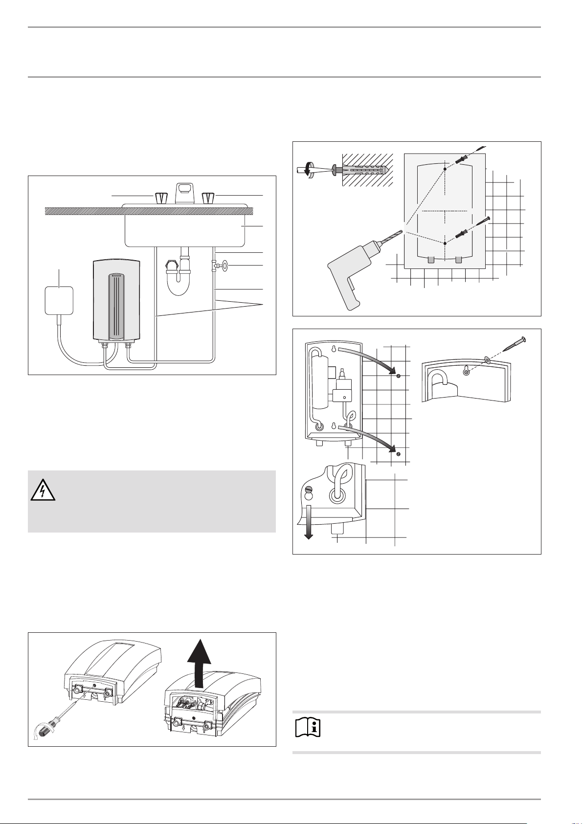
4. Mounting the unit
5. Mount unit securely to wall by putting two screws through
mounting holes. Screws and plastic wall anchors for
mounting on masonry or wood are provided.
8
1
1 Electrical junction box
2 Water supply line for faucet installation
3 3/8“ compression-T
4 Shut-off valve
5 1/2“ main pipe
6 Sink
7 Cold valve (right)
8 Hot valve (left)
7
6
5
4
3
2
26�02�02�0330
26�02�02�033126�02�02�1355
DANGER Electrocution
UNIT MUST BE INSTALLED IN A VERTICAL POSITION WITH
THE WATER FITTINGS POINTING DOWNWARD. DO NOT
INSTALL UNIT WHERE IT WOULD ROUTINELY BE SPLASHED
WITH WATER. ELECTRIC SHOCK MAY RESULT.
1. Install DHC as close as possible to the hot water draw-off
point, for example, directly underneath the sink or next to
the shower stall.
2. Install DHC in a frost free area. If frost may occur, remove
unit before freezing temperatures set in.
3. Leave a minimum of 5“ of clearance on all sides for
servicing.
4. Remove plastic cover.
5. Water connections
1. All plumbing work must comply with national and applicable
state and local plumbing codes.
2. A pressure reducing valve must be installed if the cold water
supply pressure exceeds 150 PSI (10 bar).
3. Make certain that the cold water supply line has been flushed
to remove any scale and dirt.
4. Install isolating valve in cold water line as shown in
illustration. This allows the unit to be isolated for
maintenance purposes.
5. Cold water connection (inlet) is on the right side of the unit,
hot water connection (outlet) is on the left side of unit.
Note
26�02�02�1360
EXCESSIVE HEAT FROM SOLDERING ON COPPER PIPES
NEAR THE DHC MAY CAUSE DAMAGE.
4 | DHC WWW.STIEBEL-ELTRON.COM
Page 5

INSTALLATION
ELECTRICAL CONNECTION
6. Tankless water heaters such as the DHC are not required to
be equipped with a Pressure and Temperature Relief Valve
(PTRV). If the local inspector will not pass the installation
without a PTRV, it should be installed on the hot water outlet side of unit.
7. In case you are connecting to 1/2“ water pipe, solder 1/2“
NPT tapered female adapter by copper on ends of cold and
hot water lines. In case you are connecting to 3/8“ water
pipe, use a 1/2“ female pipe thread by 3/8“ compression
adapter. Braided flexible connectors will work as well.
Connect cold and hot water lines to the unit.
8. When all plumbing work is completed, check for leaks and
take corrective action before proceeding.
6. Electrical connection
DANGER Electrocution
BEFORE BEGINNING ANY WORK ON THE ELECTRIC
INSTALLATION, BE SURE THAT MAIN BREAKER PANEL
SWITCH IS „OFF“ TO AVOID ANY DANGER OF ELECTRIC
SHOCK. ALL MOUNTING AND PLUMBING MUST BE
COMPLETED BEFORE PROCEEDING WITH ELECTRICAL
HOOK-UP. WHERE REQUIRED BY LOCAL, STATE OR
NATIONAL ELECTRICAL CODES THE CIRCUIT SHOULD BE
EQUIPPED WITH A „GROUND FAULT INTERRUPTER“.
1. All electrical work must comply with national and applicable
state and local electrical codes.
2. The DHC should be connected to a properly grounded
dedicated branch circuit of proper voltage rating. In installations with several DHC units, each unit requires an independent circuit. Please refer to the technical data table for
the correct wire and circuit breaker size.
3. The wire must be fed through the rubber seal located
between the hot and cold water connections. Then feed
wires through strain relief clamp and tighten clamp down on
wire. The „live“ wires must be connected to the slots on the
terminal block marked N and L (DHC 3-1 only) or L and L (all
other versions). The ground wire must be connected to slot
marked with the ground symbol.
4. Reinstall plastic cover.
7. Putting the water heater into
operation
WARNING
!
OPEN HOT WATER FAUCET FOR A FEW MINUTES UNTIL
WATER FLOW IS CONTINUOUS AND ALL AIR IS PURGED
FROM WATER PIPES. THE UNIT’S PLASTIC COVER MUST
BE INSTALLED BEFORE THE CIRCUIT BREAKER IS TURNED
ON.
1. Turn on circuit breaker to bring electrical power to the unit.
2. Open hot water faucet to a degree so that water flow
is „typical“ i.e. until the water flow is the same as that
encountered during normal use.
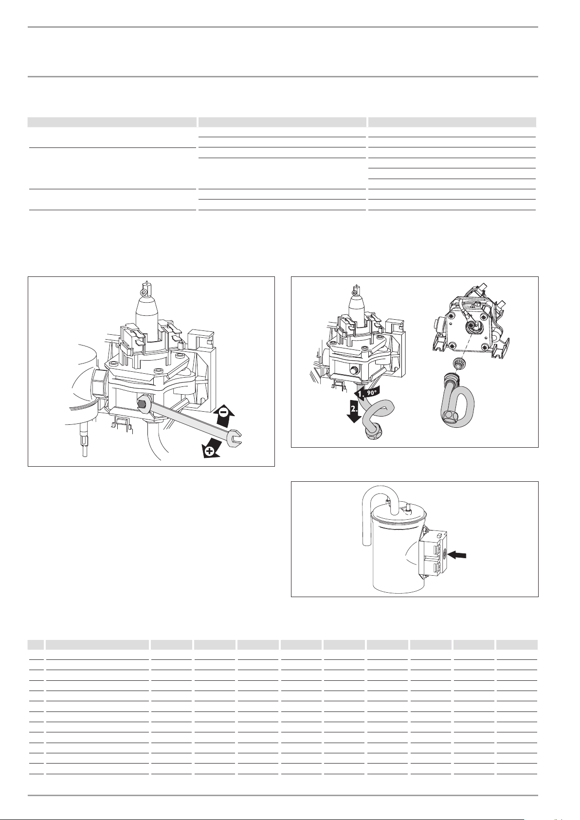
3. Wait twenty seconds until temperature has stabilized. Then
check water temperature. If temperature is too low, the
water flow rate needs to be reduced. In order to do this,
turn off the unit’s circuit breaker, remove the cover and turn
the flow adjustment screw shown in illustration clockwise
1/2 turn (180 degrees). Then reinstall plastic cover, turn on
circuit breaker and check water temperature. This procedure
should be repeated until the desired temperature is achieved.
In case the water temperature is too high, turn the flow
adjustment screw counter clockwise in the same manner
until the desired temperature is achieved. The arrows in
illustration refer to the water temperature.
4. In order to obtain temperature control at a single spout
mixer-type faucet, restrict cold water flow to faucet by
partially closing the cold water shut-off valve under the sink
until cold water and hot water flow rates are approximately
the same.
8. Normal maintenance
STIEBEL ELTRON DHC tankless heaters are designed for a very long
service life. Actual life expectancy will vary with water quality and
use. The unit itself does not require any regular maintenance.
However, to ensure consistent water flow, it is recommended
to periodically remove scale and dirt that may build up at the
aerator of the faucet or in the shower head. Also, the DHC has
a built in filter screen that should be cleaned from time to time.
In order to do this, turn off the cold water supply at the isolating
valve and remove the ground wire. Twist cold water supply tube
counterclock wise by 90° and pull towards bottom of unit. Clean
screen and put the screen, the cold water supply tube and the
ground wire back into their original position. Please be sure that
the ground wire is reinstalled and that ground screw is securely
tightened after this procedure.
ENGLISH
Note
OTHER THAN THE FILTER SCREEN, THE DHC DOES NOT
26�02�02�0469
DANGER Electrocution
AS WITH ANY ELECTRIC APPLIANCE, FAILURE TO
ELECTRICALLY GROUND UNIT MAY RESULT IN SERIOUS
INJURY OR DEATH.
WWW.STIEBEL-ELTRON.COM DHC | 5
CONTAIN ANY PARTS SERVICEABLE BY THE LAY PERSON.
IN CASE OF MALFUNCTION PLEASE CONTACT A LICENSED
PLUMBER OR ELECTRICIAN.
Page 6
INSTALLATION
TECHNICAL DATA
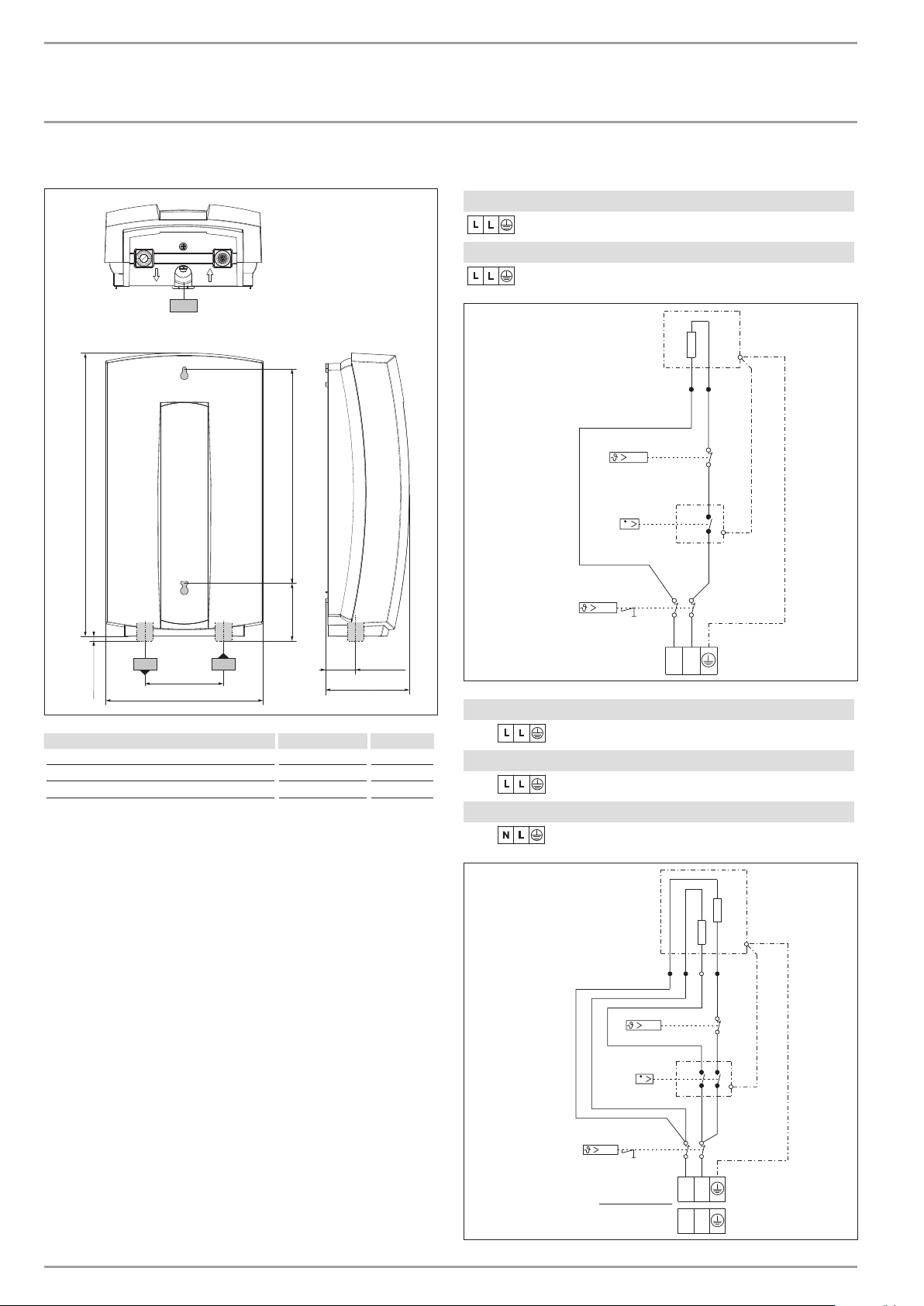
9. Technical Data
b01
360 (14.17")
9.1 Wiring diagram
DHC 3-2, DHC 4-2, DHC 5-2
2/GRD ~ 208 / 240 V
DHC 4 -3
2/GRD ~ 277 V
273 (10.75")75 (2.953")
V
c06
c06 c01
8 (0.315")
b01 electrical supply cable
c01 cold water connection " NPT 1/2
c06 hot water connection " NPT 1/2
100 (3.94")
200 (7.88")
c01
38 (1.5")
110 (4.33")
D0000021558
DHC 6-2, DHC 8-2, DHC 10-2
A
DHC 9 -3
A
DHC 3-1
B
2/GRD ~ 208 / 240 V
2/GRD ~ 277 V
1/N/GRD ~ 120 V
V
LL
85�02�02�0008
A
B
LL
NL
6 | DHC WWW.STIEBEL-ELTRON.COM
85�02�02�0009
Page 7
INSTALLATION
TEMPERATURE INCREASE ABOVE AMBIENT WATER TEMPERATURE
9.2 Data table
Model DHC 3-1 DHC 3-2 DHC 4-2 D HC 4-3 DHC 5-2 DHC 6-2 DHC 8-2 DH C 9-3 DHC 10-2
074050 074052 074053 074051 074054 074424 074055 232204 074056
Voltage V 120 208 240 208 240 277 208 240 208 240 208 240 277 208 240
Phase 1 1 1 1 1 1 1 1 1 1 1 1 1 1 1
Wattage kW 3.0 2.5 3.5 2.9 3.8 4.5 3.6 4.8 4.5 6.0 5.4 7.2 9.0 7. 2 9.6
Ampere A 25 12 14 14 16 17 18 20 22 25 26 30 32.5 35 40
Min. required circuit breker size A 30 15 20 20 20 20 30 30 30 30 30 40 40 50 50
Recommended wire size AWG Copper 10 14 12 12 12 12 10 10 10 10 8 8 8 8 8
Min. water flow to activate unit GPM / l/min 0.32 / 1.2 0.32 / 1.2 0.42 / 1.6 0.42 / 1.6 0.42 / 1.6 0.48 / 1.8 0.69 / 2.6 0.79 / 3.0 0.79 / 3.0
Pressure loss in unit PSI / bar 2.88 / 0.23 2.88 / 0.23 2.88 / 0.23 2.88 / 0.23 2.88 / 0.23 2.88 / 0.23 3.13 / 0.25 3.75 / 0.30 3.75 / 0.30
Nominal water volume GAL / l 0.13 / 0.5 0.13 / 0.5 0.13 / 0.5 0.13 / 0.5 0.13 / 0.5 0.13 / 0.5 0.13 / 0.5 0.13 / 0.5 0.13 / 0.5
Working pressure max, PSI / bar 150 / 10 150 / 10 150 / 10 150 / 10 150 / 10 150 / 10 150 / 10 150 / 10 150 / 10
Tested to pressure PSI / bar 300 / 20 300 / 20 300 / 20 300 / 20 300 / 20 300 / 20 300 / 20 300 / 20 300 / 20
Weight lbs. / kg 4.6 / 2.1 4.6 / 2.1 4.6 / 2.1 4.6 / 2.1 4.6 / 2.1 5.3 / 2.4 5.3 / 2.4 5.3 / 2.4 5.3 / 2.4
Water connections " NPT 1/2 1/2 1/2 1/2 1/2 1/2 1/2 1/2 1/2
- Suitable for supply with cold water
- Tankless water heaters are considered a non-continuous load
- Conductors should be sized to maintain a voltage drop of less
than 3 % under load
ENGLISH
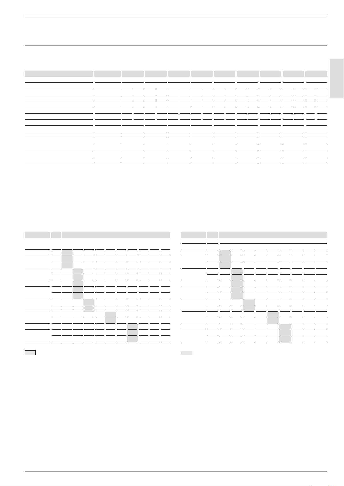
10. Temperature increase above
ambient water temperature
[ °F ]
Typ kW GPM (gallon per minute)
0.32 0.42 0.48 0.5 0.69 0.75 0.79 1.0 1.5 2.0
DHC 3-1 3.0 65 49 43 41 30 27 26 20 14 10
DHC 3-2
3.3 71 53 47 45 33 30 28 22 15 11
DHC 4-2
3.8 – 61 54 52 38 35 33 26 17 13
DHC 4-3 4.5 – 73 64 61 45 41 39 31 20 15
DHC 5-2
4.8 – 77 68 65 48 44 41 33 22 16
DHC 6-2
6.0 – – 85 82 60 55 52 41 27 20
DHC 8-2
7.2 – – – – 71 65 62 49 33 25
DHC 9-3 9.0 - - - - - - 77 58 41 31
DHC 10-2
9.6 – – - – – – 82 65 44 33
2.5 54 40 35 34 25 23 21 17 11 9
2.9 – 47 41 40 29 26 25 20 13 10
3.6 – 58 51 49 36 33 31 25 16 12
4.5 – – 64 61 45 41 39 31 20 15
5.4 – – – – 54 49 46 37 25 18
7.2 – – - – – – 62 49 33 25
Min. water flow to activate unit
[ °C ]
Typ / Type kW l/min
1.2 1.6 1.8 2.0 2.6 3.0 4.0 5.0 7.5
DHC 3-1
DHC 3-2
3.3 39 30 26 24 18 16 12 9 6
DHC 4-2
3.8 – 34 30 27 21 18 14 11 7
DHC 4-3
DHC 5-2
4.8 – 43 38 34 26 23 17 14 9
DHC 6-2
6.0 – – 48 43 33 29 22 17 11
DHC 8-2
7.2 – – – – 40 34 26 21 14
DHC 9-3 9.0 - - - - - 43 32 26 17
DHC 10-2
9.6 – – – – – 46 34 28 18
3.0 36 27 24 22 17 14 11 9 6
2.5 30 22 20 18 14 12 9 7 5
2.9 – 26 23 21 16 14 10 8 6
4.5 – 40 36 32 25 22 16 13 9
3.6 – 32 29 26 20 17 13 10 7
4.5 – – 36 32 25 22 16 13 9
5.4 – – – – 30 26 19 15 10
7.2 – – – – – 34 26 21 14
Min. water flow to activate unit
WWW.STIEBEL-ELTRON.COM DHC | 7
Page 8
INSTALLATION
TROUBLESHOOTING
11. Troubleshooting
Symptom Possible cause Solution
No hot water but audible click can be heard when
water is turned on
No hot water and no audible click can be heard when
water is turned on
clean filter screen at DHC unit.
Water not warm enough
voltage too low supply correct voltage to unit.
If you are not able to resolve a problem please contact us toll free at 800-582-8423 before removing the unit from the wall.
STIEBEL ELTRON is happy to provide technical assistance. In most instances, we can resolve the problem over the phone.
circuit breaker off circuit breaker on.
safety thermal cut-out tripped reset thermal cut-out.
water flow too low to activate flow switch clean faucet aerator.
open shut-off valve completely.
open flow adjustment screw.
water flow too high reduce wter flow, close flow agjusment screw.
Open flow adjustment screw
Filter screen
26�02�02�1358
Reset button from safety thermal cut out
26�02�02�1356
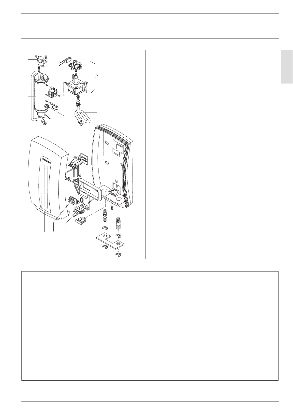
12. Spare parts
No. Spare part DHC 3-1 DHC 3-2 DHC 4-2 DHC 4-3 DHC 5-2 DHC 6-2 DHC 8-2 D HC 9-3 DHC 10-2
1 Heating system 165889 167769 167770 165890 167771 171117 167772 296874 167773
2 Flow switch 165273 165273 162162 162162 162162 171105 162164 162465 162165
3 Thermostat 162472 162472 162472 162472 162472 162472 162472 162472 162472
4 Switch 168026 168026 168026 168026 168026 168026 168026 168026 168026
5 Housing (back) 165891 165891 165891 165891 165891 165891 165891 165891 165891
6 Plumbing connection 165893 165893 165893 165893 165893 165893 165893 165893 165893
7 Housing (front) 165892 165892 165892 165892 165892 165892 165892 165892 165892
8 Safety thermal cut out 162474 162474 162474 162474 162474 162474 162474 162474 162474
9 Wiring block 026010 026010 026010 026010 026010 026010 026010 026010 026010
10 Copper tube 162314 162314 162314 162314 162314 162314 162314 162314 162314
11 Module chassis 162462 162462 162462 162462 162462 162462 162462 162462 162462
12 Wire strain relief clamp 055754 055754 055754 055754 055754 055754 055754 055754 055754
8 | DHC WWW.STIEBEL-ELTRON.COM
26�02�02�1357
Page 9
INSTALLATION
4
713
9
12
8
Warranty
The warranty conditions of our German companies do not
apply to appliances acquired outside of Germany. In countries
where our subsidiaries sell our products, it is increasingly the
case that warranties can only be issued by those subsidiaries.
Such warranties are only granted if the subsidiary has issued
its own terms of warranty. No other warranty will be granted.
We shall not provide any warranty for appliances acquired in
countries where we have no subsidiary to sell our products.
This will not aect warranties issued by any importers.
Environment and recycling
We would ask you to help protect the environment.
dispose of the various materials in accordance with national
regulations.
DATE OF PURCHASE. SHOULD THE PART(S) PROVE TO BE DEFECTIVE UNDER NORMAL USE DURING THIS PERIOD, STIEBEL ELTRON,
INC. WILL BE RESPONSIBLE FOR REPLACEMENT OF THE DEFECTIVE PART(S) ONLY. STIEBEL ELTRON, INC. IS NOT RESPONSIBLE FOR
INSTALLATION | ENVIRONMENT AND RECYCLING| WARRANTY
SPARE PARTS
SPARE PARTS
After use,
11
10
2
5
ENGLISH
6
26�02�02�1359
WARRANTY
RESIDENTIAL & COMMERCIAL WARRANTY: STIEBEL ELTRON WARRANTS TO THE ORIGINAL OWNER THAT THE INSTANTANEOUS
WATER HEATER WILL BE FREE FROM DEFECTS IN WORKMANSHIP AND MATERIALS FOR A PERIOD OF THREE YEARS FROM THE
LABOR CHARGES TO REMOVE AND/OR REPLACE THE DEFECTIVE PART(S), OR ANY INCIDENTIAL OR CONSEQUENTIAL EXPENSES.
SHOULD THE OWNER WISH TO RETURN THE INSTANTANEOUS WATER HEATER FOR REPAIR, THE OWNER MUST FIRST SECURE
WRITTEN AUTHORIZATION FROM STIEBEL ELTRON, INC. THE OWNER SHALL BE REQUIRED TO SHOW PROOF OF PURCHASE DATE,
AND TO PAY ALL TRANSPORTATION COSTS TO RETURN THE DEFECTIVE PART(S) OR INSTANTANEOUS WATER HEATER FOR REPAIR
OR REPLACEMENT. WARRANTY IS VOID IF WATER HEATER HAS BEEN INSTALLED OR USED IMPROPERLY OR IF DESIGN HAS BEEN
ALTERED IN ANY WAY.
STIEBEL ELTRON, INC.
17 West Street
West Hatfield, MA 01088, USA
PHONE: 800-582-8423 or 413-247-3380
FAX: 413-247-3369
E-Mail info@stiebel-eltron-usa.com
www.stiebel-eltron-usa.com
WWW.STIEBEL-ELTRON.COM DHC | 9
Page 10

TABLE DES MATIÈRES | UTILISATION
REMARQUES GÉNÉRALES
UTILISATION
1. Remarques générales ������������������������������������� 10
1.1 Informations relatives à la sécurité ������������������������� 10
1.2 Autres repérages utilisés dans ce document ��������������10
2. Sécurité ����������������������������������������������������� 10
2.1 Utilisation conforme ������������������������������������������� 11
2.2 Informations générales ���������������������������������������� 11
2.3 Précautions de sécurité���������������������������������������� 11
2.4 Label de conformité �������������������������������������������� 11
INSTALLATION
3. Montage de l’appareil ������������������������������������� 12
4. Raccordements d’eau �������������������������������������� 12
5. Raccordement électrique ���������������������������������� 13
6. Mise en œuvre du chauffe-eau �������������������������� 13
7. Maintenance normale ������������������������������������� 13
8. Caractéristiques techniques ������������������������������ 14
8.1 Wiring diagram ������������������������������������������������� 14
8.2 Tableau de données �������������������������������������������� 15
9. Elévation de température au delà de la température
ambiante de l’eau ������������������������������������������ 15
10. Dépannage �������������������������������������������������� 16
11. Pièces de rechange ���������������������������������������� 16
ENVIRONNEMENT ET RECYCLAGE | GARANTIE
1.1 Informations relatives à la sécurité
1.1.1 Structure des consignes de sécurité
MOT-CLÉ Nature du danger
Ici s’affichent les conséquences possibles de la nonobservation des prescriptions de sécurité.
Les mesures permettant d’éviter ces dangers
sont également indiquées.
1.1.2 Symboles, nature du danger
Symbole Nature du danger
Blessure
!
1.1.3 Mots-clés
MOT- CLÉ Description
DANGER La non-observation de ces informations entraîne des
AVERTISSEMENT La non-observation de ces informations peut entraîner des
ATTENTION La non-observation de ces informations peut entraîner des
Électrocution
Brûlures ou ébouillantements
blessures graves, voire la mort.
blessures graves, voire la mort.
blessures moyennement graves ou légères.
UTILISATION
1. Remarques générales
Remarque
Lisez attentivement cette notice avant d‘utiliser l‘appareil
et familiarisez-vous avec ses fonctions. Conservez la notice dans un endroit sûr. Remettez cette notice au nouvel
utilisateur le cas échéant.
1.2 Autres repérages utilisés dans ce document
Remarque
Les remarques sont délimitées par des lignes horizontales
au-dessus et en dessous du texte. Les remarques d’ordre
général sont caractérisées par le symbole représenté ici
à gauche.
Lisez attentivement ces remarques.
Symbole
Dommages sur l’appareil et sur l’environnement
!
Ce symbole indique ce que vous devez faire. Ce que vous
devez faire est décrit étape par étape.
Recyclage de l’appareil
2. Sécurité
Respectez les consignes suivantes et les prescriptions de sécurité.
N’utilisez cet appareil que s’il est complètement installé et doté
de tous les dispositifs de sécurité.
10 | DHC WWW.STIEBEL-ELTRON.COM
Page 11

UTILISATION
SÉCURITÉ
2.1 Utilisation conforme
L’appareil est destiné au chauffage de l’eau sanitaire et peut un
point de soutirage.
Toute utilisation dépassant ces spécifications est considérée
comme non conforme.
Le respect de la présente notice faite également partie de
l’utilisation conforme de cet appareil.
2.2 Informations générales
Lisez la notice en sa totalité. La non-observation de toutes les
directives, notices et réglementations peut entraîner des blessures
corporelles et/ou des dégâts matériels. Une installation, un
paramétrage, une modification ou une maintenance effectué(e) de
manière incorrecte sur cet appareil peut entraîner des blessures
très importantes.
Cet appareil doit être installé par un installateur agréé. L’installation
doit satisfaire à toutes les prescriptions nationales, régionales et
locales. L’installateur est responsable de la réalisation correcte
de l’installation. La non-observation de la notice d’installation et
d’emploi ou toute installation non-conforme invalide la garantie.
Conservez la présente notice pour consultation ultérieure.
L’installateur doit remettre cette notice à l’utilisateur.
En cas de questions à propos de l’installation, de l’utilisation et de
l’exploitation de ce préparateur d’eau chaude sanitaire, ou bien si
vous avez besoin de manuels d’installation supplémentaires, merci
de contacter le numéro de téléphone de l’assistance technique
(voir la dernière page).
2.3 Précautions de sécurité
DANGER Blessure
!
Lisez et respectez la présente notice.
Le non-observation de cette notice peut entraîner des
blessures très graves, voire la mort.
Dommages sur l’appareil et sur l’environnement
!
L’appareil doit être installé par un installateur agréé.
L’installation doit satisfaire à toutes les prescriptions
nationales, régionales et locales.
La maintenance de l’appareil doit être effectuée par un
installateur qualifié.
DANGER Électrocution
Avant d’effecteur les travaux d’installation, de
paramétrage, de modification ou de maintenance
sur cet appareil, coupez tous les disjoncteurs et
sectionneurs de l’alimentation électrique de l’appareil.
La non-observation de ces consignes peut entraîner des
blessures très graves, voire la mort.
DANGER Électrocution
Ne retirez le capot de l’appareil qu’une fois l’alimentation
électrique de l’appareil coupée. La non-observation de
cette consigne peut entraîner des blessures, voire la
mort.
DANGER Électrocution
L’appareil doit être relié correctement à la terre. L’absence de liaison à la terre du produit peut entraîner des
blessures très graves, voire la mort.
DANGER Brûlures
L’eau à des températures supérieures à 52°C (125°F)
peut entraîner des brûlures immédiates graves, voire la
mort par ébouillantement.
AVERTISSEMENT Risque de blessures
!
Si des enfants ou des personnes aux capacités physiques,
sensorielles ou mentales réduites sont autorisées à
utiliser cet appareil, il convient de s’assurer qu’ils
l’utilisent uniquement quand ils sont supervisés ou s’ils
ont été instruits par la personne responsable de leur
sécurité.
Veillez à ce que les enfants ne jouent pas avec l’appareil.
2.4 Label de conformité
Voir la plaque signalétique de l’appareil.
Le chauffe-eau DHC sans accumulateur diffère à plusieurs égards
des chauffe-eau conventionnels à ballon d’eau chaude. Il ne stocke
pas d’eau chaude. En fait, l’eau est chauffée instantanément
lorsqu’elle passe dans l’appareil. Les puissants éléments
chauffants sont activés par un commutateur de débit lorsque l’eau
est tirée d’un robinet d’eau chaude relié au DHC. Comme il n’y
a pas de perte due à la réserve d’eau, le DHC a une plus grande
efficacité énergétique que les chauffe-eau à accumulation.
La température de l’eau chaude fournie par le DHC dépend de
la puissance de l’élément chauffant, de la température de l’eau
froide d’arrivée et du débit de l’eau à travers l’appareil. Afin que
le DHC fonctionne correctement, il doit répondre exactement à
son application.
Au cas où vous auriez des questions sur la manière dont vous
prévoyez d’utiliser le DHC, n’hésitez pas à appeler notre service
technique au n°800-582-8423 (USA et Canada). Pour le service
après-vente dans les autres pays, appelez nous au n°413-2473380 aux USA, vous pouvez aussi nous envoyer un e-mail à
l’adresse info@stiebel-eltron-usa.com ou nous envoyer un fax
au n°suivant: 413-247-3369.
Le DHC peut être utilisé pour se laver les mains, aux USA et au
Canada:
- Lavabos dans les toilettes de locaux commerciaux /
industriels et d’habitations
- Cuisines dans les locaux commerciaux / industriels et les
habitations
- Cabines
- Usages spéciaux dans les magasins de développement de
photos, les laboratoires, etc.
Le DHC peut aussi être utilisé pour des appartements entiers et des
habitations dans des zones à climat chaud comme dans la région
des caraïbes, l’Amérique Centrale et le Mexique en raison des
températures d’eau ambiante plus élevées.
Français
WWW.STIEBEL-ELTRON.COM DHC | 11
Page 12

INSTALLATION
MONTAGE DE L’APPAREIL
INSTALLATION
3. Montage de l’appareil
8
1
1 Boîte de raccordement électrique
2 Conduite d’alimentation en eau pour installation à robinet
3 T de réduction 3/8‘’
4 Vanne de fermeture
5 Tuyau principal ½’’
6 Evier
7 Robinet d’eau (droit)
8 Robinet d’eau (gauche)
7
5. Fixer solidement l’appareil en faisant coulisser les trous
6
5
4
3
2
26�02�02�0330
de montage sur les deux vis préalablement fixées au mur.
Les vis et les chevilles en plastique pour montage sur
maçonnerie ou bois sont fournies.
26�02�02�1360
26�02�02�033126�02�02�1355
DANGER Électrocution
L’APPAREIL DOIT ETRE INSTALLE EN POSITION VERTICALE
AVEC LES SORTIES D’EAU DIRIGEES VERS LE BAS. NE
PAS INSTALLER L’APPAREIL A UN ENDROIT OU IL SERAIT
REGULIERE MENT ECLABOUSSE. UN CHOC ELECTRIQUE
POURRAIT EN RESULTER.
1. Installer le DHC aussi près que possible du point de tirage
d’eau chaude, par exemple directement en dessous de
l’évier ou juste à côté de la cabine de douche.
2. Installer le DHC dans une zone non exposée au gel. En cas
de risque de gel, enlever l’appareil avant l’apparition des
températures négatives.
3. Laisser un minimum de 5‘’ d’espace libre sur tous les côtés
pour la maintenance.
4. Enlever le cache en plastique.
4. Raccordements d’eau
1. Tout le travail de plomberie doit répondre aux normes de
plomberie nationales et locales applicables.
2. Une vanne de réduction de pression doit être installée si
la pression d’alimentation d’eau froide dépasse 150 PSI
(10bar).
3. Assurez-vous que la conduite d’alimentation d’eau froide a
été purgée pour enlever tout dépôt ou saleté.
12 | DHC WWW.STIEBEL-ELTRON.COM
Page 13

INSTALLATION
RACCORDEMENT ÉLECTRIQUE
4. Installer une vanne d’isolation dans la conduite d’eau froide
comme le montre l’illustration. Cela permet à l’appareil
d’être isolé pour des opérations de maintenance.
5. Le raccordement d’eau froide (entrée) est situé du côté droit
de l’appareil, le raccordement d’eau chaude (sortie) est situé
du côté gauche de l’appareil.
Remarque
UNE CHALEUR EXCESSIVE DE SOUDAGE SUR LES TUYAUX
DE CUIVRE A PROXIMITE DU DHC PEUT CAUSER DES
DEGATS.
26�02�02�0469
Français
6. Les chauffe-eau sans accumulateur tels que le DHC n’ont
pas besoin d’être équipés d’une vanne de décharge de
température et de pression. Si l’inspecteur local n’agrée pas
l’installation sans cette vanne, la vanne devra être installée
du côté de la sortie d’eau chaude de l’appareil.
7. Si vous faites un branchement à un tuyau d’eau d’½’’,
soudez un adaptateur femelle conique de ½’’ NPT avec du
cuivre aux extrémités des conduites d’eau froide et d’eau
chaude. Si vous faites un branchement à un tuyau d’eau
de 3/8‘’, utilisez un tuyau femelle d’1/2‘’ fileté avec un
adaptateur de réduction de 3/8‘’. Les raccords flexibles
tressés conviendront également. Connectez les conduites
d’eau froide et d’eau chaude à l’appareil.
8. Lorsque tout le travail de plomberie est terminé, chercher
les fuites et prendre une action corrective avant d’aller plus
loin.
5. Raccordement électrique
DANGER Électrocution
AVANT DE COMMENCER TOUTE OPERATION SUR
L’INSTALLATION ELECTRIQUE, S’ASSURER QUE
L’INTERRUPTEUR DU DISJONCTEUR PRINCIPAL EST
EN POSITION ”ARRET” POUR EVITER TOUT RISQUE
D’ELECTROCUTION. TOUTES OPERATIONS DE MONTAGE
ET DE PLOMBERIE DOIVENT ETRE TERMINEES AVANT DE
PROCEDER A L’ASSEMBLAGE ELECTRIQUE. SI LES NORMES
ELECTRIQUES LOCALES OU NATIONALES L’EXIGENT, LE
CIRCUIT DOIT ETRE EQUIPE D’UN ”INTERRUPTEUR DE
TERRE”.
1. Toutes les opérations électriques doivent répondre aux
normes électriques nationales et locales applicables.
2. Le DHC doit être relié à un circuit de branchement dédié,
correctement mis à la terre et d’une tension adéquate.
Dans les installations ayant plusieurs DHC, chaque unité a
besoin d’un circuit indépendant. Se référer au tableau de
caractéristiques techniques pour la bonne taille des câbles et
du coupe-circuit.
3. Le câble doit être alimenté à travers le joint de caoutchouc
situé entre les branchements de l’eau chaude et de l’eau
froide. Ensuite, faire passer le câble à travers le collier de
serrage et resserrer le collier sur le câble. Les extrémités
dénudées des câbles doivent être insérées dans les fentes sur
le bloc terminal marqué N et L (pour le DHC 3-1 seulement)
ou L et L (pour toutes les autres versions). Le conducteur de
terre doit être inséré dans la fente identifiée par le symbole
de la terre.
4. Réinstaller le cache en plastique.
DANGER Électrocution
COMME AVEC N’IMPORTE QUEL APPAREIL ELECTRIQUE,
L’ABSENCE DE MISE A LA TERRE PEUT ENTRAINER LA
MORT
6. Mise en œuvre du chauffe-eau
ATTENTION
!
OUVRIR LE ROBINET D’EAU CHAUDE QUELQUES MINUTES
AVANT QUE LE DEBIT D’EAU SOIT CONTINU ET QUE TOUT
L’AIR SOIT PURGE DES CANALISATIONS D’EAU. LE CACHE
EN PLASTIQUE DE L’APPAREIL DOIT ETRE INSTALLE AVANT
QUE LE DISJONCTEUR SOIT MIS EN POSITION DE MARCHE.
1. Mettre le disjoncteur en position de ”marche” pour amener
l’électricité à l’appareil.
2. Ouvrir le robinet d’eau chaude à un degré tel que
l’écoulement d’eau soit ”typique” c’est-à-dire avant que
l’écoulement d’eau soit le même que celui qu’on rencontre
en utilisation normale.
3. Attendre vingt secondes jusqu’à ce que la température soit
stabilisée. Ensuite, vérifier la température de l’eau. Si la
température est trop basse, le débit d’eau doit être réduit.
Pour ce faire, fermer le disjoncteur de l’appareil, enlever
le cache et tourner la vis de réglage de débit, montrée
dans l’illustration, d’un ½ tour (à 180 degrés) dans le
sens horaire. Ensuite, réinstaller le cache en plastique,
remettre le disjoncteur en position ”marche” et vérifier
la température de l’eau. Cette procédure doit être répétée
jusqu’à ce que la température désirée soit atteinte. Au cas
où la température de l’eau est trop élevée, tourner de la
même manière la vis de réglage de débit dans le sens antihoraire jusqu’à ce que la température désirée soit atteinte.
Les flèches dans l’illustration se réfèrent à la température de
l’eau.
4. Afin d’obtenir le contrôle de la température sur un robinet
unique de type mitigeur, limiter le débit d’eau froide au
robinet en fermant partiellement la vanne de fermeture
d’eau froide sous l’évier jusqu’à ce que les débits d’eau
froide et d’eau chaude soient approximativement les mêmes.
7. Maintenance normale
Les chauffe-eau DHC de STIEBEL ELTRON sont conçus pour une très
longue durée de vie. La durée de vie réelle escomptée va varier
avec la qualité et l’utilisation de l’eau. L’appareil lui-même ne
nécessite pas de maintenance régulière. Cependant, pour assurer
un écoulement d’eau homogène, il est recommandé d’enlever
périodiquement les dépôts et saletés qui peuvent se constituer
sur l’évent du robinet ou dans la pomme de douche. Le DHC a
WWW.STIEBEL-ELTRON.COM DHC | 13
Page 14

INSTALLATION
CARACTÉRISTIQUES TECHNIQUES
aussi un écran de filtrage intégré qui doit être nettoyé de temps en
temps. Pour ce faire, fermer l’alimentation d’eau froide à la vanne
d’isolation et enlever le conducteur de mise à la terre. Tourner le
tube d’alimentation d’eau froide dans le sens anti-horaire à 90° et
tirer vers le fond de l’appareil. Nettoyer le filtre et remettre dans
leur position d’origine le filtre, le tube d’alimentation d’eau froide
et le conducteur de mise à la terre. S’assurer que le conducteur
de mise à la terre est réinstallé et que la vis de mise à la terre est
bien serrée après cette procédure.
Remarque
MIS A PART LE FILTRE, LE DHC NE CONTIENT AUCUNE
PIECE NECESSITANT UN ENTRETIEN PATICULIER. EN
CAS DE MAUVAIS FONCTIONNEMENT, CONTACTER UN
PLOMBIER OU UN ELECTRICIEN PROFESSIONNEL.
8. Caractéristiques techniques
b01
8.1 Wiring diagram
DHC 3-2, DHC 4-2, DHC 5-2
2/GRD ~ 208 / 240 V
DHC 4 -3
2/GRD ~ 277 V
V
360 (14.17")
c06
c06 c01
8 (0.315")
b01 Câble d’alimentation secteur
c01 Raccord d’eau froide " NPT 1/2
c06 Raccord d’eau chaude sanitaire " NPT 1/2
100 (3.94")
200 (7.88")
c01
273 (10.75")75 (2.953")
38 (1.5")
110 (4.33")
DHC 6-2, DHC 8-2, DHC 10-2
A
DHC 9 -3
A
DHC 3-1
B
D0000021558
2/GRD ~ 208 / 240 V
2/GRD ~ 277 V
1/N/GRD ~ 120 V
V
LL
85�02�02�0008
A
B
LL
NL
14 | DHC WWW.STIEBEL-ELTRON.COM
85�02�02�0009
Page 15

INSTALLATION
ELÉVATION DE TEMPÉRATURE AU DELÀ DE LA TEMPÉRATURE AMBIANTE DE L’EAU
8.2 Tableau de données
Modèle
074050 074052 074053 074051 074054 074424 074055 232204 074056
Voltage V 120 208 240 208 240 277 208 240 208 240 208 240 277 208 240
Phase 1 1 1 1 1 1 1 1 1 1 1 1 1 1 1
Puissance kW 3.0 2.5 3.5 2.9 3.8 4.5 3.6 4.8 4.5 6.0 5.4 7.2 9.0 7.2 9.6
Intensité A 25 12 14 14 16 17 18 20 22 25 26 30 32.5 35 40
Taille minimale nécessaire du
disjoncteur
Taille des fils de cuivre AWG cuivre 10 14 12 12 12 12 10 10 10 10 8 8 8 8 8
Ecoulement d’eau minimum pour
activer l’appareil
Perte de pression dans l’appareil PSI / bar 2.88 / 0.23 2.88 / 0.23 2.88 / 0.23 2.88 / 0.23 2.88 / 0.23 2.88 / 0.23 3.13 / 0.25 3.75 / 0.30 3.75 / 0.30
Volume d’eau nominal GAL / l 0.13 / 0.5 0.13 / 0.5 0.13 / 0.5 0.13 / 0.5 0.13 / 0.5 0.13 / 0.5 0.13 / 0.5 0.13 / 0.5 0.13 / 0.5
Pression de travail maximale PSI / bar 150 / 10 150 / 10 150 / 10 150 / 10 150 / 10 150 / 10 150 / 10 150 / 10 150 / 10
Testée à la pression PSI / bar 300 / 20 300 / 20 300 / 20 300 / 20 300 / 20 300 / 20 300 / 20 300 / 20 300 / 20
Poids libres / kg 4.6 / 2.1 4.6 / 2.1 4.6 / 2.1 4.6 / 2.1 4.6 / 2.1 5.3 / 2.4 5.3 / 2.4 5.3 / 2.4 5.3 / 2.4
Branchements d’eau " NPT 1/2 1/2 1/2 1/2 1/2 1/2 1/2 1/2 1/2
GPM / l/min 0.32 / 1.2 0.32 / 1.2 0.42 / 1.6 0.42 / 1.6 0.42 / 1.6 0.48 / 1.8 0.69 / 2.6 0.79 / 3.0 0.79 / 3.0
DHC 3-1 DHC 3-2 DHC 4-2 D HC 4-3 DHC 5-2 DHC 6-2 DHC 8-2 DH C 9-3 DHC 10-2
A 30 15 20 20 20 20 30 30 30 30 30 40 40 50 50
- Convenant pour l’alimentation en eau froide
- Les chauffe-eau sans accumulateur sont considérés comme charge non continue
- Les conducteurs doivent être calibrés pour maintenir une chute de tension de moins de 3% sous charge
9. Elévation de température au delà
de la température ambiante de
l’eau
Français
[ °F ]
Typ / Type kW GPM ( galones per minute )
0.32 0.42 0.48 0.5 0.69 0.75 0.79 1.0 1.5 2.0
DHC 3-1 3.0 65 49 43 41 30 27 26 20 14 10
DHC 3-2
3.3 71 53 47 45 33 30 28 22 15 11
DHC 4-2
3.8 – 61 54 52 38 35 33 26 17 13
DHC 4-3 4.5 – 73 64 61 45 41 39 31 20 15
DHC 5-2
4.8 – 77 68 65 48 44 41 33 22 16
DHC 6-2
6.0 – – 85 82 60 55 52 41 27 20
DHC 8-2
7.2 – – – – 71 65 62 49 33 25
DHC 9-3 9.0 - - - - - - 77 58 41 31
DHC 10-2
9.6 – – - – – – 82 65 44 33
2.5 54 40 35 34 25 23 21 17 11 9
2.9 – 47 41 40 29 26 25 20 13 10
3.6 – 58 51 49 36 33 31 25 16 12
4.5 – – 64 61 45 41 39 31 20 15
5.4 – – – – 54 49 46 37 25 18
7.2 – – - – – – 62 49 33 25
Débit d’eau minimum pour activer l’appareil
[ °C ]
Typ / Type kW l/min
1.2 1.6 1.8 2.0 2.6 3.0 4.0 5.0 7.5
DHC 3-1
DHC 3-2
3.3 39 30 26 24 18 16 12 9 6
DHC 4-2
3.8 – 34 30 27 21 18 14 11 7
DHC 4-3
DHC 5-2
4.8 – 43 38 34 26 23 17 14 9
DHC 6-2
6.0 – – 48 43 33 29 22 17 11
DHC 8-2
7.2 – – – – 40 34 26 21 14
DHC 9-3 9.0 - - - - - 43 32 26 17
DHC 10-2
9.6 – – – – – 46 34 28 18
3.0 36 27 24 22 17 14 11 9 6
2.5 30 22 20 18 14 12 9 7 5
2.9 – 26 23 21 16 14 10 8 6
4.5 – 40 36 32 25 22 16 13 9
3.6 – 32 29 26 20 17 13 10 7
4.5 – – 36 32 25 22 16 13 9
5.4 – – – – 30 26 19 15 10
7.2 – – – – – 34 26 21 14
Débit d’eau minimum pour activer l’appareil
WWW.STIEBEL-ELTRON.COM DHC | 15
Page 16

INSTALLATION
DÉPANNAGE
10. Dépannage
Symptôme Causse possible Solution
Pas d’eau chaude mais on entend un cliquetis quand
l’eau est ouverte
Pas d’eau chaude et on n’entend pas de cliquetis
quand l’eau est ouverte
nettoyer le filtre sur l’appareil DHC.
L’eau n’est pas assez chaude
tension trop basse fournir la tension correcte à l’appareil.
Si vous n’arrivez pas à résoudre un problème, contacter nous en appelant le numéro gratuit 800-582-8423 avant d’enlever l’appareil
du mur. STIEBEL ELTRON est heureuse de vous fournir son assistance technique. Dans la plupart des cas, il s’agit d’un problème que
nous pouvons résoudre par téléphone.
disjoncteur fermé mettre le disjoncteur en marche.
le disjoncteur de sécurité s’est déclenché réarmer le disjoncteur.
l’écoulement d’eau est trop bas pour activer le
commutateur de débit
écoulement d’eau trop haut réduire l’écoulement d’eau, fermer la vis de réglage
nettoyer l’évent du robinet.
ouvrir complètement la vanne de fermeture.
ouvrir la vis de réglage de débit.
de l’écoulement.
Réglage du débit
Nettoyage du filtre
Bouton de réarmement du disjoncteur de sécurité
26�02�02�1358
26�02�02�1356
11. Pièces de rechange
N° de pièce de rechange DHC 3-1 DHC 3-2 DHC 4-2 DHC 4-3 DHC 5-2 DHC 6-2 DHC 8-2 D HC 9-3 DHC 10-2
1 Système de chauffage 165889 167769 167770 165890 167771 171117 167772 296874 167773
2 Commutateur de débit 165273 165273 162162 162162 162162 171105 162164 162465 162165
3 Thermostat 162472 162472 162472 162472 162472 162472 162472 162472 162472
4 Commutateur 168026 168026 168026 168026 168026 168026 168026 168026 168026
5 Carter (arrière) 165891 165891 165891 165891 165891 165891 165891 165891 165891
6 Branchement de plomberie 165893 165893 165893 165893 165893 165893 165893 165893 165893
7 Carter (avant) 165892 165892 165892 165892 165892 165892 165892 165892 165892
8 Disjoncteur thermique de sécurité 162474 162474 162474 162474 162474 162474 162474 162474 162474
9 Bloc de câblage 026010 026010 026010 026010 026010 026010 026010 026010 026010
10 Tube de cuivre 162314 162314 162314 162314 162314 162314 162314 162314 162314
11 Châssis du module 162462 162462 162462 162462 162462 162462 162462 162462 162462
12 Collier de serrage 055754 055754 055754 055754 055754 055754 055754 055754 055754
16 | DHC WWW.STIEBEL-ELTRON.COM
26�02�02�1357
Page 17

INSTALLATION | GARANTIE | ENVIRONNEMENT ET RECYCLAGE
4
713
9
12
8
Eltron, Inc. n’est responsable que du remplacement de la ou des pièces défectueuses. STIEBEL ELTRON, INC. n’est pas responsable
Si le propriétaire souhaite renvoyer le chauffe-eau instantané électrique pour réparation, il doit d’abord obtenir l’autorisation écrite
de Stiebel Eltron, Inc. Le propriétaire sera tenu de produire la preuve de la date d’achat et de supporter tous les frais de transport
La garantie ne couvre pas les installations ou utilisations incorrectes du chauffe-eau ni les modifications de conception éventuelles.
PIÈCES DE RECHANGE
2
-
11
10
Français
5
6
26�02�02�1359
GARANTIE
Garantie applicable aux utilisateurs privés et commerciaux: STIEBEL ELTRON garantit au propriétaire initial que le chauffe-eau
instantané électrique TEMPRA est exempt de défauts de fabrication et de matériaux pendant une période de trois ans à compter
de la date d’achat. En cas de défaut avéré d’une ou plusieurs pièces lors d’une utilisation normale durant cette période, Stiebel
des frais de main-d’œuvre découlant de la dépose et/ou du remplacement de la ou des pièces défectueuses ni des éventuels
frais accessoires ou indirects.
inhérents au renvoi de la ou des pièces défectueuses ou du chauffe-eau instantané électrique pour réparation ou remplacement.
STIEBEL ELTRON, INC.
17 West Street
West Hatfield, MA 01088, USA
PHONE: 800-582-8423 or 413-247-3380
FAX: 413-247-3369
E-Mail info@stiebel-eltron-usa.com
www.stiebel-eltron-usa.com
WWW.STIEBEL-ELTRON.COM DHC | 17
Page 18

ÍNDICE|OPERACIÓN
INDICACIONES GENERALES
OPERACIÓN
1. Indicaciones generales ������������������������������������ 18
1.1 Indicaciones para el cableado: �������������������������������18
1.2 Otras marcas presentes en este documento �������������� 18
2. Seguridad ��������������������������������������������������� 18
2.1 Uso previsto ������������������������������������������������������ 19
2.2 Información general ������������������������������������������� 19
2.3 Medidas de seguridad ����������������������������������������� 19
2.4 Sello de certificación ������������������������������������������� 19
3. General ������������������������������������������������������ 19
INSTALACIÓN
4. Instalación física ������������������������������������������� 20
5. Conexión de agua ������������������������������������������ 20
6. Conexión ���������������������������������������������������� 21
7. Operacion de la unidad ������������������������������������ 21
8. Mantenimiento ��������������������������������������������� 21
9. Datos técnicos ���������������������������������������������� 22
9.1 Diagrama eléctrico ��������������������������������������������� 22
9.2 Tabla de especificaciones ������������������������������������� 23
10. Aumento de temperatura del agua ���������������������� 23
11. Resolución de incidencias (troubleshooting) ������������ 24
12. Repuestos ��������������������������������������������������� 24
MEDIO AMBIENTE Y RECICLADO | GARANTIA
1.1 Indicaciones para el cableado:
1.1.1 Estructura de las indicaciones de seguridad
ADVERTENCIA de tipo de peligro
Aquí aparecen las posibles consecuencias del
desobedecimiento de las indicaciones de seguridad.
Se indican las medidas necesarias para evitar
estos peligros.
1.1.2 Símbolos, tipo de peligro
Símbolo Tipo de peligro
Lesión
!
1.1.3 Palabras clave
PALABRA CLAVE Descripción
PELIGRO El desobedecimiento de esta información conlleva
ADVERTENCIA El desobedecimiento de esta información puede
ATENCIÓN
Electrocución
Quemadura o escaldamiento
graves lesiones o la muerte
conllevar graves lesiones o la muerte
El desobedecimiento de esta información puede
conllevar lesiones de mediana gravedad o lesiones
leves
OPERACIÓN
1. Indicaciones generales
Indicación
Lea atentamente estas instrucciones antes de utilizar el
aparato y familiarícese con sus funciones. Conserve este
manual en un lugar seguro. Si entregara este aparato a
otros usuarios no olvide incluir el manual.
1.2 Otras marcas presentes en este documento
Indicación
La indicación está limitada por líneas horizontales sobre y
bajo el texto. La información general se señaliza mediante
el símbolo que se muestra a la izquierda.
Lea atentamente las indicaciones.
Símbolo
Daños en el aparato y al medio ambiente
!
Este símbolo indica que debe usted hacer algo. Lo que debe
hacer se describe en pasos individuales.
Eliminación del aparato
2. Seguridad
Observe las siguientes indicaciones y normas de seguridad.
El equipo sólo debe utilizarse después de haber sido instalado
completamente y con todos los dispositivos de seguridad.
18 | DHC WWW.STIEBEL-ELTRON.COM
Page 19

OPERACIÓN
GENERAL
2.1 Uso previsto
El aparato está previsto para el calentamiento del agua potable y
puede abastecer una punto de extracción.
El uso fuera de las especificaciones descritas se considera
indebido.
Además, el obedecimiento de las presentes instrucciones forma
parte del uso previsto de este aparato.
2.2 Información general
Lea el manual íntegramente. El desobedecimiento de las normas,
instrucciones y reglamentos puede causar lesiones físicas a
personas y/o daños materiales. La instalación, ajuste, modificación
y mantenimiento incorrectos del presente aparato puede conducir
a lesiones físicas considerables.
Este aparato debe ser instalado por un técnico autorizado. La
instalación debe cumplir toda la normativa nacional, regional
y local. El técnico especializado es responsable de la correcta
instalación. El desobedecimiento de las instrucciones de
instalación y operación o el uso indebido conducen a la anulación
de la garantía.
Guarde el presente manual para futuras consultas. El técnico
especializado debe entregar este manual al usuario.
En caso de cualquier consulta relativa a la instalación, uso u
operación del presente calentador o, si fuera preciso en relación
a cualquier otro manual de instalación, diríjase al teléfono de
servicio técnico (véase última página).
2.3 Medidas de seguridad
PELIGRO Electrocución
El aparato debe conectarse a tierra adecuadamente. Si
no se conecta a tierra el producto pueden producirse
graves lesiones físicas o incluso la muerte.
PELIGRO Quemaduras
Las temperaturas del agua que superen los 125 °F (52 °C)
pueden causar quemaduras graves repentinas o incluso
la muerte por escaldamiento.
ADVERTENCIA Peligro de lesiones
!
Si niños o personas con discapacitación física, sensorial o
mentalmente, operan el aparato debe asegurarse de que
dicha operación se realice después de haber recibido la
instrucción adecuada por una persona a su cargo.
En el caso de los niños debe procurar que no jueguen
con el aparato.
2.4 Sello de certificación
Consulte la placa de especificaciones del aparato.
3. General
Los calentadores de agua DHC difieren de los calentadores
de tanque en muchas maneras. Este calentador no almacena
agua caliente. Al contario, calienta el agua instantáneamente
cuando esta fluye a través de la unidad. El poderoso elemento
que calienta, es activado solamente cuando se abre una llave de
agua caliente la cual esta conectada al sistema alimentado por
el calentador.
ESPAÑOL
PELIGRO de lesiones
!
Lea y obedezca las siguientes instrucciones.
El desobedecimiento de esta información puede conllevar
graves lesiones o la muerte.
Daños en el aparato y al medio ambiente
!
Este aparato debe ser instalado por un técnico autorizado.
La instalación debe cumplir toda la normativa nacional,
regional y local.
El mantenimiento del aparato debe ser realizado por
técnicos autorizados.
PELIGRO Electrocución
Antes de llevar a cabo cualquier tarea de instalación,
ajuste, modificación o mantenimiento de este aparato
deben desconectarse todos los interruptores de potencia
y seccionadores de alimentación eléctrica del aparato. El
desobedecimiento de estas indicaciones puede conllevar
graves lesiones o la muerte.
PELIGRO Electrocución
Sólo podrá retirar la cubierta del aparato si se ha
interrumpido la alimentación eléctrica del aparato. El
desobedecimiento de estas indicaciones puede conllevar
lesiones físicas o la muerte.
Usos
Los calentadores eléctricos DHC son ideales para el uso en casas,
apartamentos o cabañas en áreas de un clima subtropical y
tropical como el Caribe, muchas partes de México, Centro América
y América del Sur.
Los modelos DHC ocupan muy poco espacio, son fáciles de instalar
y proveen agua caliente continua y sin limite. Se pueden usar con
sistemas eléctricos bien sea de 60 Hz o de 50 Hz.
La unidad se activa solo cuando hay demanda para agua caliente,
evitando así, consumo y gasto innecesario de energía eléctrica
y de agua.
Los importantes ahorros en el consumo de electricidad que
ofrecen los modelos DHC pueden llegar hasta un 50 % cuando
se comparan con el consumo de los calentadores eléctricos tipo
”tanque”.
WWW.STIEBEL-ELTRON.COM DHC | 19
Page 20

INSTALACIÓN
INSTALACIÓN FÍSICA
INSTALACIÓN
4. Instalación física
8
1
1 caja eléctrica
2 linea de agua
3 entrada a válvula T-3/8”
4 válvula de servicio
5 reducido a ½”
6 lavamanos
7 válvula de agua fría
8 válvula de agua caliente
7
5. Conexión de agua de suplido (entrada) es al lado derecho de
6
5
4
3
2
26�02�02�0330
la unidad. La conexión de agua caliente (salida) debe ser al
lado izquierdo de la unidad.
26�02�02�1360
26�02�02�033126�02�02�1355
PELIGRO Electrocución
LA UNIDAD DEBE INSTALARSE EN POSICIÓN VERTICAL
CON LAS CONEXIÓNES DE AGUA EN LA PARTE DE ABAJO.
NO INSTALE LA UNIDAD DONDE PUEDA MOJARSE, ESTO
PODRÍA OCASIONAR UNA DESCARGA ELÉCTRICA.
1. Todo trabajo de plomería debe cumplir con los códigos de
plomería. Nacional y/o Local.
2. Una válvula reductora de presión debe ser instalada si la
línea de suplido de agua exede una presión de 150 PSI.
3. Asegúrese de dejar correr el agua por la línea de suplido
antes de cualquier conexión para eliminar cualquier depósito
o sucio en la mísma.
4. Instalar válvula de servicio en línea de suplido de agua . Esto
permite aislar la unidad para propósitos de mantenimiento.
5. Conexión de agua
1. Todo trabajo de plomería debe cumplir con los códigos de
plomería. Nacional y/o Local.
2. Una válvula reductora de presión debe ser instalada si la
línea de suplido de agua exede una presión de 150 PSI.
3. Asegúrese de dejar correr el agua por la línea de suplido
antes de cualquier conexión para eliminar cualquier depósito
o sucio en la mísma.
20 | DHC WWW.STIEBEL-ELTRON.COM
Page 21

INSTALACIÓN
CONEXIÓN
4. Instalar válvula de servicio en línea de suplido de agua. Esto
permite aislar la unidad para propósitos de mantenimiento.
5. Conexión de agua de suplido (entrada) es al lado derecho de
la unidad. La conexión de agua caliente (salida) debe ser al
lado izquierdo de la unidad.
Nota
CALOR EXESIVO DE LAS SOLDADURAS EN LAS LINEAS DE
COBRE PUEDE CAUSAR DAÑOS AL CALENTADOR.
6. El calentador de agua DHC no requiere una válvula de alivio
por presión y temperarura (PTRV). Si el inspector la requiere
se debe instalarla después de la salida de agua caliente de la
unidad.
7. Conectar uniones de ½ (media) pulgada NPT a sus
respectivas líneas de agua fría o caliente. Proveer reductores
cuando estos sean necesarios sin el código de plomería
Nacional y/o Local.
8. Cuando finalice el trabajo de plomería verifique si hay goteos
y corrija estos antes de proceder.
6. Conexión
PELIGRO Electrocución
ANTES DE COMENZAR LA INSTALACION ELECTRICA
ASEGURESE DE QUE EL INTERRUPTOR TERMOMAGNETICO
PRINCIPAL DEL PANEL ELECTRICO ESTE APAGADO PARA
EVITAR POSIBLE DESCARGA ELECTRICA.
NOTA: TODA INSTALACION ELECTRICA Y DE PLOMERIA
DEBE COMPLETARSE ANTES DE ENCENDER EL
INTERRUPTOR TERMOMAGNETICO PRINCIPAL. EL
CIRCUITO DEBE SER EQUIPADO CON UN INTERRUPTOR DE
CONEXIÓN A TIERRA („GROUND FAULT INTERRUPTER“)
CUANDO SEA REQUERIDO POR EL CODIGO ELECTRICO
NACIONAL Y/O LOCAL.
1. Todo trabajo eléctrico debe cumplir con las dispociciones
del Colegio de Peritos Electricistas y Códigos Nacionales y/o
Locales.
2. La unidad DHC debe tener su circuito independiente
utilizando tres alambres de cobre de tamaño apropiado
y protegido por un interruptor termomagnético (breaker)
correctamente seleccionado. Para instalar varias unidades
DHC se requiere un circuito independiente para cada una.
3. La cableria debe entrar a la unidad a través del sello de
goma localizado en la parte inferior de la mísma entre las
conexiónes de agua fría y caliente. Alimente los cables a
través de la abrazadera localizada dentro de la unidad y
ajuste esta firmemente contra los cables. Los cables vivos
deben ser conectados en los terminales N y L para los modelos DHC 3-1. El DHC 3-2 y en todos los demás modelos los
cables vivos deben ser conectadas en los terminales L y L
(Favor ver diagramas eléctrico).
4. Reinstalar cubierta plástica. El cable de conexión a tierra
„ground“ debe ser conectado al terminal marcado con el
simbolo de tierra.
PELIGRO Electrocución
COMO CUALQUIER OTRO APARATO ELECTRICO EL NO
CONECTARLO A TIERRA PUEDE RESULTAR EN UNA
DESCARGA ELECTRICA, GRAVE LESION Y/O INCLUSO
OCASIONAR MUERTE.
7. Operacion de la unidad
ADVERTENCIA
!
ABRA LA LLAVE DE AGUA CALIENTE POR VARIOS MINUTOS
HASTA QUE EL FLUJO DE AGUA SEA CONTINUO Y TODO EL
AIRE HAYA SALIDO DE LA TUBERIA.
LA COBERTURA PLASTICA DE LA UNIDAD DEBE SER
INSTALADA ANTES DE ENCENDER EL „BREAKER“ DEL
CIRCUITO.
1. Encender el „breaker“ del circuito para proveer corriente a la
unidad. Abrir la llave de agua caliente a un punto típico, o
sea, hasta que el flujo de agua sea igual al de uso normal.
Espere 60 segundos hasta que la temperatura se estabilize.
2. Probar temperatura del agua, si la temperatura es muy
baja, el flujo de agua debe ser reducido. Para reducir el
flujo apague el „ „breaker“ de circuito, remueva cobertura
plástica y dele media vuelta (180 grados) en dirección
manecillas del reloj („clockwise“) al tornillo de ajuste de
flujo.
3. Reinstale cobertura plástica, encienda el „breaker“ y
verifique la temperatura del agua nuevamente. Este
procedimiento debe repetirse hasta que se obtenga la
temperatura de agua deseada. Por lo contrario, si la
temperatura de agua es muy alta ajuste el tornillo de flujo,
en contra de las manecillas del reloj (counterclockwise) de la
misma manera hasta obtener la temperatura deseada.
4. Para obtener control de temperatura con una llave tipo
mezcladora, restrinja el flujo de agua fría a la mezcladora
cerrando parcialmente la llave de paso de dicha
mezcladora hasta tanto el flujo de agua fría y caliente sean
aproximadamente iguales.
8. Mantenimiento
Los calentadores de agua Stiebel Eltron DHC estan diseñados para
una larga y duradera vida de servicio. La vida util del equipo
depende de la calidad de agua y del uso. La unidad, de por
si, no requiere de ningún tipo de mantenimiento. Sin embargo,
para asegurar el flujo de agua se recomienda que se remuevan
los depósitos que puedan acumularse en el filtro („aerator“) del
lavamanos o en las duchas.
26�02�02�0469
ESPAÑOL
WWW.STIEBEL-ELTRON.COM DHC | 21
Page 22

INSTALACIÓN
DATOS TÉCNICOS
Nota
EN CASO DE MAL FUNCIONMENTO DEL EQUIPO
FAVOR SOLICITAR LOS SERVICIOS DE UN PLOMERO O
ELECTRICISTA CERTIFICADO. POR FAVOR NO INTENTE
REPARARLO USTED MISMO.
9. Datos técnicos
b01
9.1 Diagrama eléctrico
DHC 3-2, DHC 4-2, DHC 5-2
2/GRD ~ 208 / 240 V
DHC 4 -3
2/GRD ~ 277 V
V
360 (14.17")
c06
c06 c01
8 (0.315")
b01 Cable de alimentación
c01 Conexión de agua fría " NPT 1/2
c06 Conexión de agua caliente " NPT 1/2
100 (3.94")
200 (7.88")
c01
273 (10.75")75 (2.953")
38 (1.5")
110 (4.33")
DHC 6-2, DHC 8-2, DHC 10-2
A
DHC 9 -3
A
DHC 3-1
B
D0000021558
2/GRD ~ 208 / 240 V
2/GRD ~ 277 V
1/N/GRD ~ 120 V
V
LL
85�02�02�0008
A
B
LL
NL
22 | DHC WWW.STIEBEL-ELTRON.COM
85�02�02�0009
Page 23

INSTALACIÓN
AUMENTO DE TEMPERATURA DEL AGUA
9.2 Tabla de especificaciones
Modelo DHC 3-1 DHC 3-2 DHC 4-2 D HC 4-3 DHC 5-2 DHC 6-2 DHC 8-2 DH C 9-3 DHC 10-2
074050 074052 074053 074051 074054 074424 074055 232204 074056
Voltaje V 120 208 240 208 240 277 208 240 208 240 208 240 277 208 240
Fase 1 1 1 1 1 1 1 1 1 1 1 1 1 1 1
Potencia de funcionamiento kW 3.0 2.5 3.5 2.9 3.8 4.5 3.6 4.8 4.5 6.0 5.4 7. 2 9.0 7.2 9.6
Corriente nominal AMPS A 25 12 14 14 16 17 18 20 22 25 26 30 32.5 35 40
Tamaño Mínimo Requerido del
Interruptor Auto. „Breaker“
Sección transversal recomendada AWG Cobre 10 14 12 12 12 12 10 10 10 10 8 8 8 8 8
Min. flujo Req. GPM / l/min 0.32 / 1.2 0.32 / 1.2 0.42 / 1.6 0.42 / 1.6 0.42 / 1.6 0.48 / 1.8 0.69 / 2.6 0.79 / 3.0 0.79 / 3.0
Caida en presión PSI / bar 2.88 / 0.23 2.88 / 0.23 2.88 / 0.23 2.88 / 0.23 2.88 / 0.23 2.88 / 0.23 3.13 / 0.25 3.75 / 0.30 3.75 / 0.30
Volumen de agua GAL / l 0.13 / 0.5 0.13 / 0.5 0.13 / 0.5 0.13 / 0.5 0.13 / 0.5 0.13 / 0.5 0.13 / 0.5 0.13 / 0.5 0.13 / 0.5
Presión máxima PSI / bar 150 / 10 150 / 10 150 / 10 150 / 10 150 / 10 150 / 10 150 / 10 150 / 10 150 / 10
Presión de prueba PSI / bar 300 / 20 300 / 20 300 / 20 300 / 20 300 / 20 300 / 20 300 / 20 300 / 20 300 / 20
Peso lbs / kg 4.6 / 2.1 4.6 / 2.1 4.6 / 2.1 4.6 / 2.1 4.6 / 2.1 5.3 / 2.4 5.3 / 2.4 5.3 / 2.4 5.3 / 2.4
Conexcion de tubería " NPT 1/2 1/2 1/2 1/2 1/2 1/2 1/2 1/2 1/2
- Apropiado para el suministro de agua fría
- Calentador instantáneo no admisible para el funcionamiento constante
- Los cables deben dimensionarse de forma que sean capaces de mantener un descenso de tensión de menos del 3% bajo carga.
A 30 15 20 20 20 20 30 30 30 30 30 40 40 50 50
ESPAÑOL
10. Aumento de temperatura del agua
[ °F ]
Typ / Type kW GPM (galones por minuto)
0.32 0.42 0.48 0.5 0.69 0.75 0.79 1.0 1.5 2.0
DHC 3-1 3.0 65 49 43 41 30 27 26 20 14 10
DHC 3-2
3.3 71 53 47 45 33 30 28 22 15 11
DHC 4-2
3.8 – 61 54 52 38 35 33 26 17 13
DHC 4-3 4.5 – 73 64 61 45 41 39 31 20 15
DHC 5-2
4.8 – 77 68 65 48 44 41 33 22 16
DHC 6-2
6.0 – – 85 82 60 55 52 41 27 20
DHC 8-2
7.2 – – – – 71 65 62 49 33 25
DHC 9-3 9.0 - - - - - - 77 58 41 31
DHC 10-2
9.6 – – - – – – 82 65 44 33
2.5 54 40 35 34 25 23 21 17 11 9
2.9 – 47 41 40 29 26 25 20 13 10
3.6 – 58 51 49 36 33 31 25 16 12
4.5 – – 64 61 45 41 39 31 20 15
5.4 – – – – 54 49 46 37 25 18
7.2 – – - – – – 62 49 33 25
Flujo de agua mínimo para activar la unidad.
[ °C ]
Typ / Type kW l/min
1.2 1.6 1.8 2.0 2.6 3.0 4.0 5.0 7.5
DHC 3-1
DHC 3-2
3.3 39 30 26 24 18 16 12 9 6
DHC 4-2
3.8 – 34 30 27 21 18 14 11 7
DHC 4-3
DHC 5-2
4.8 – 43 38 34 26 23 17 14 9
DHC 6-2
6.0 – – 48 43 33 29 22 17 11
DHC 8-2
7.2 – – – – 40 34 26 21 14
DHC 9-3 9.0 - - - - - 43 32 26 17
DHC 10-2
9.6 – – – – – 46 34 28 18
3.0 36 27 24 22 17 14 11 9 6
2.5 30 22 20 18 14 12 9 7 5
2.9 – 26 23 21 16 14 10 8 6
4.5 – 40 36 32 25 22 16 13 9
3.6 – 32 29 26 20 17 13 10 7
4.5 – – 36 32 25 22 16 13 9
5.4 – – – – 30 26 19 15 10
7.2 – – – – – 34 26 21 14
Flujo de agua mínimo para activar la unidad.
WWW.STIEBEL-ELTRON.COM DHC | 23
Page 24

INSTALACIÓN
RESOLUCIÓN DE INCIDENCIAS (TROUBLESHOOTING)
11. Resolución de incidencias (troubleshooting)
Síntoma Posible causa Solución
No hay agua caliente pero se escucha el „click“ al
abrir agua caliente.
No hay agua caliente y no se oye el „click“. no hay flujo de agua suficiente para activar unidad
limpie el filtro en el dispositivo.
Agua no calienta suficiente
voltaje muy bajo ó incorrecto suministrar voltaje correcto.
If you are not able to resolve a problem please contact us toll free at 800-582-8423 before removing the unit from the wall.
STIEBEL ELTRON is happy to provide technical assistance. In most instances, we can resolve the problem over the phone.
se cayó el breaker usar breaker adecuado..
protección termal activada oprimir protector termal (botón)
limpiar „aerators“.
abrir valvula al máximo
abrir tornillo de ajuste de flujo.
demasiado flujo de agua disminuir flujo de agua (cerrar tornillo de ajuste.
Caudal de paso máximo onfigurar
Rejilla de filtrado
26�02�02�1358
Protección termal con botón de activación
26�02�02�1356
12. Repuestos
No. Piezas de recambio DHC 3-1 DHC 3-2 DHC 4-2 DHC 4 -3 DHC 5-2 DHC 6-2 DHC 8-2 DHC 9-3 DHC 10-2
1 Sistema de Calentamiento 165889 167769 167770 165890 167771 171117 167772 296874 167773
2 Interruptor de Flujo 165273 165273 162162 162162 162162 171105 162164 162465 162165
3 Termostato 162472 162472 162472 162472 162472 162472 162472 162472 162472
4 Interruptor 168026 168026 168026 168026 168026 168026 168026 168026 168026
5 Caja Exterior (parte trasera) 165891 165891 165891 165891 165891 165891 165891 165891 165891
6 Conexiónes de Tubería 165893 165893 165893 165893 165893 165893 165893 165893 165893
7 Caja Exterior (parte delantera) 165892 165892 165892 165892 165892 165892 165892 165892 165892
8 Interruptor de Seguridad (temperatura) 162474 162474 162474 162474 162474 162474 162474 162474 162474
9 Bloque de Alambrado 026010 026010 026010 026010 026010 026010 026010 026010 026010
10 Tubo de Cobre 162314 162314 162314 162314 162314 162314 162314 162314 162314
11 Armazón Interior 162462 162462 162462 162462 162462 162462 162462 162462 162462
12 Abrazadera para Cables Eléctricos 055754 055754 055754 055754 055754 055754 055754 055754 055754
24 | DHC WWW.STIEBEL-ELTRON.COM
26�02�02�1357
Page 25

INSTALACIÓN | MEDIO AMBIENTE Y RECICLADO | GARANTIA
STIEBEL ELTRON GARANTIZA AL DUEÑO ORIGINAL QUE EL CALENTADOR DE AGUA; ESTARA LIBRE DE DEFECTOS DE MANO DE OBRA
SI EL DUEÑO DESEA DEVOLVER EL CALENTADOR DE AGUA PARA REPARACION SERA RESPONSABILIDAD DEL MISMO, EL ASEGURARSE
4
713
9
12
8
Garantía
Para los aparatos adquiridos fuera de Alemania no son aplica-
bles las condiciones de garantía de nuestras sociedades ale-
manas. Además, en los países en los que alguna de nuestras
liales comercialice nuestros productos, la garantía sólo será
otorgada por dicha lial. Este tipo de garantía únicamente se
otorgará si la lial hubiera publicado unas condiciones de ga-
rantía propias. No se otorgará ninguna garantía adicional.
No otorgamos ninguna garantía para aquellos aparatos adqui-
ridos en países en los que ninguna de nuestras liales comer-
cialicen nuestros productos. Cualquier garantía asegurada por
el importador permanecerá inalterada.
Medio ambiente y reciclado
Colabore para proteger nuestro medio ambiente. Elimine los
materiales después de su uso conforme a la normativa nacional
vigente.
REPUESTOS
2
10
5
11
GARANTIA RESIDENCIAL Y COMERCIAL.
ESPAÑOL
6
26�02�02�1359
GARANTIA
Y MATERIALES POR UN PERIODO DE 3 AÑOS DESDE EL DIA DE COMPRA. SI ALGUNA PARTE DE ESTE PRUEBA ESTAR DEFECTUOSA
BAJO USO NORMAL DURANTE ESTE PERIODO, STIEBEL ELTRON SE HACE RESPONSABLE POR EL REEMPLAZO DE SOLAMENTE LAS
PARTES DEFECTUOSAS. STIEBEL ELTRON NO SE HACE RESPONSABLE POR COSTOS DE LABOR DEBIDO A LA REMOCION O REPARACIÓN DE PARTES DEFECTUOSAS Y POR INCIDENTES O GASTOS CONSECUENTES.
PRIMERO DE OBTENER UNA AUTORIZACION ESCRITA DE STIEBEL ELTRON. AL DUEÑO SE LE EXIGIRA PRUEBA DE FECHA DE COMPRA Y PAGAR TODOS LOS GASTOS NECESARIOS PARA LA TRANSPORTACION DE PIEZAS DEFECTUOSAS PARA SER REEMPLAZADAS.
LA GARANTIA SE ANULARIA SI EL CALENTADOR HA SIDO INSTALADO O UTILIZADO INADECUADAMENTE, O SI EL DISEÑO HA SIDO
ALTERADO DE ALGUNA MANERA.
STIEBEL ELTRON, INC.
17 West Street
West Hatfield, MA 01088, USA
PHONE: 800-582-8423 or 413-247-3380
FAX: 413-247-3369
E-Mail info@stiebel-eltron-usa.com
www.stiebel-eltron-usa.com
WWW.STIEBEL-ELTRON.COM DHC | 25
Page 26

Notas
26 | DHC WWW.STIEBEL-ELTRON.COM
Page 27

Notas
ESPAÑOL
WWW.STIEBEL-ELTRON.COM DHC | 27
Page 28

STIEBEL ELTRON, Inc.
17 West Street | 01088 West Hatfield MA
Tel. 0413 247-3380 | Fax 0413 247-3369
info@stiebel-eltron-usa.com
www.stiebel-eltron-usa.com
4<AMHCMM=gfijea>
Subject to errors and technical changes! | Salvo error o modificación técnica! |
Sous réserve d‘erreurs et de modifications techniques!
Subject to errors and technical changes! Stand 8643
A 165894-37245-8832
 Loading...