

Page 1

OPERATING AND INSTALLATION
OPERACIÓN E INSTALACIÓN
UTILISATION ET INSTALLATION
DHW HEAT PUMP WATER HEATER
CALENTADOR DE AGUA CON BOMBA ELÉCTRICA DE CALOR
CHAUFFE-EAU THERMODYNAMIQUE
» ACCELERA® 300
A 280011-36221-8653
STIEBEL ELTRON Inc.
17 West Street | West Hatfield MA 01088
Tel. 413-247-3380 | Fax 413-247-3369
Email info@stiebel-eltron-usa.com
www.stiebel-eltron-usa.com
The Accelera® 300 Heat
Pump Water Heater is tested
and certified by WQA against
NSF/ANSI 372 for lead free
compliance.
Page 2
2 | ACCELERA® 300 HEAT PUMP WATER HEATER WWW.STIEBEL-ELTRON-USA.COM
GENERAL INFORMATION
QUICK START-UP GUIDE
Please read
Read these instructions carefully and retain them for
future reference. If the water heater is passed on to
a third party please hand these instructions to the
new user.
This manual includes important information regarding the safe
and efficient handling of the water heater. Keep this manual with
the water heater at all times.
Work must only be carried out by a licensed installer who has read
and understands these instructions. All federal, state, and local
codes must be followed. Failure to do so may result in equipment
failure, serious injury, or death.
While working on the water heater, disconnect the power supply.
Illustrations in these instructions are designed to aid a general
understanding and may deviate from the actual water heater
version. No claims can be derived from such illustrations.
Limited liability:
We have collated all details and information in this manual in due
consideration of applicable standards and regulations, the state of
the art and our long-term know-how and experience.
Losses due to the following are excluded from our liability:
- Non-observance of these instructions
- Incorrect use
- Installation of the water heater by unqualified personnel
- Unauthorized modifications
- Technical modifications
- Use of unauthorized spare parts
Copyright:
These operating and installation instructions are subject to
copyright.
Transferring these instructions to third parties, copying of any
kind, either in total or extracts therefrom, as well as their use
and/or conveying its contents are prohibited without our written
consent.
Contraventions are liable to claims for compensation. Further
claims are reserved.
We hold the copyright:
STIEBEL ELTRON Inc.
17 West Street | West Hatfield MA 01088
Tel. 413-247-3380 | Fax 413-247-3369
Email info@stiebel-eltron-usa.com
www.stiebel-eltron-usa.com
Should you have any question regarding the installation or
operation of the water heater, please contact our customer service.
Tel. (USA) 800-582-8423 or 413-247-3380
Please record your serial number and information
Serial No.:
____________________________________________________________________
Date of Purchase:
____________________________________________________________
Accelera® 300 Quick Start-up Guide
A. OVERVIEW: This water heater hooks up like any other electric water heater, with a few minor exceptions. Be sure to follow
all state and local codes during installation. This page is not intended to be a substitute for the installation manual. Be
sure to follow all safety precautions.
B. UNPACKING: DO NOT unpack water heater unit until it is located at the point of installation. Follow all instructions in the
manual and be sure to use caution, as this unit is top heavy. DO NOT lay the unit down and DO NOT jar or tip the unit past
45 degrees on the hand truck. See: 10.6
C. INSTALLATION / WATER:
a. Location: Find a suitable location according to the manual. Minimum area is 10’ x 10’ x 8’. Be sure vents are parallel to
the wall with the fan facing the most open area along that wall. Please note: a drain pan is recommended. See: 10.6
b. 3/4” Inlet from union provided. For hook-up, follow all state and local codes for check valves, expansion tanks, shut off
valves, gauges, etc. Install a 70 psi pressure reduction valve.
Please note: water pressure should not exceed 0.48 MPa (70 psi). See: 10.7
c. 3/4” Outlet from union to hot water line.
d. Install T&P Relief valve (supplied). Please note: 0.69 MPa / 99 °C (100 psi / 210 °F).
D. CONDENSATE DRAIN: Goes directly into a drain or use a condensate pump to drain into a suitable location. See: 10.6.1
E. FILL & FLUSH TANK: Run water and be sure tank is full prior to turning on the electricity.
F. INSTALLATION / ELECTRICAL: Use a 240 Volt / 15 Amp double pole breaker and connect to water heater L1, L2, and
Ground. See: 16.2
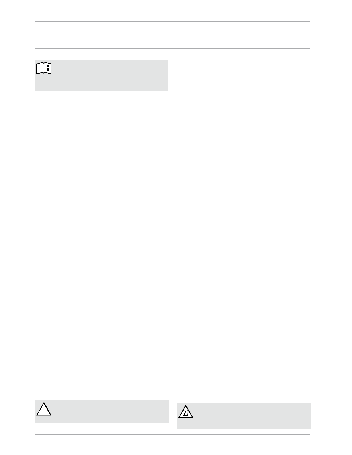
!
WITHIN ABOUT 5 HOURS OF START-UP TIME, EXHAUST
AIR FLOW SHOULD BE APPROXIMATELY -14,4°C (6°F)
LESS THAN THE INLET SIDE.
CAUTION: RISK OF SCALDING.
THERE IS A RISK OF SCALDING AT OUTLET
TEMPERATURES EXCEEDING 43 °C (110°F) RISK OF
SCALDING
Page 3
WWW.STIEBEL-ELTRON-USA.COM ACCELERA 300 | 3
QUICK START-UP GUIDE | OPERATION
REQUIRED ROOM DIMENSIONS AND CLEARANCES
15
2´
8
´
Air flow
intake
Air flow
intake
Air flow
exhaust
Air flow
exhaust
2´
2´
2´
Air flow
intake
Air flow
exhaust
´
2
´´ x 8´
D0000018502
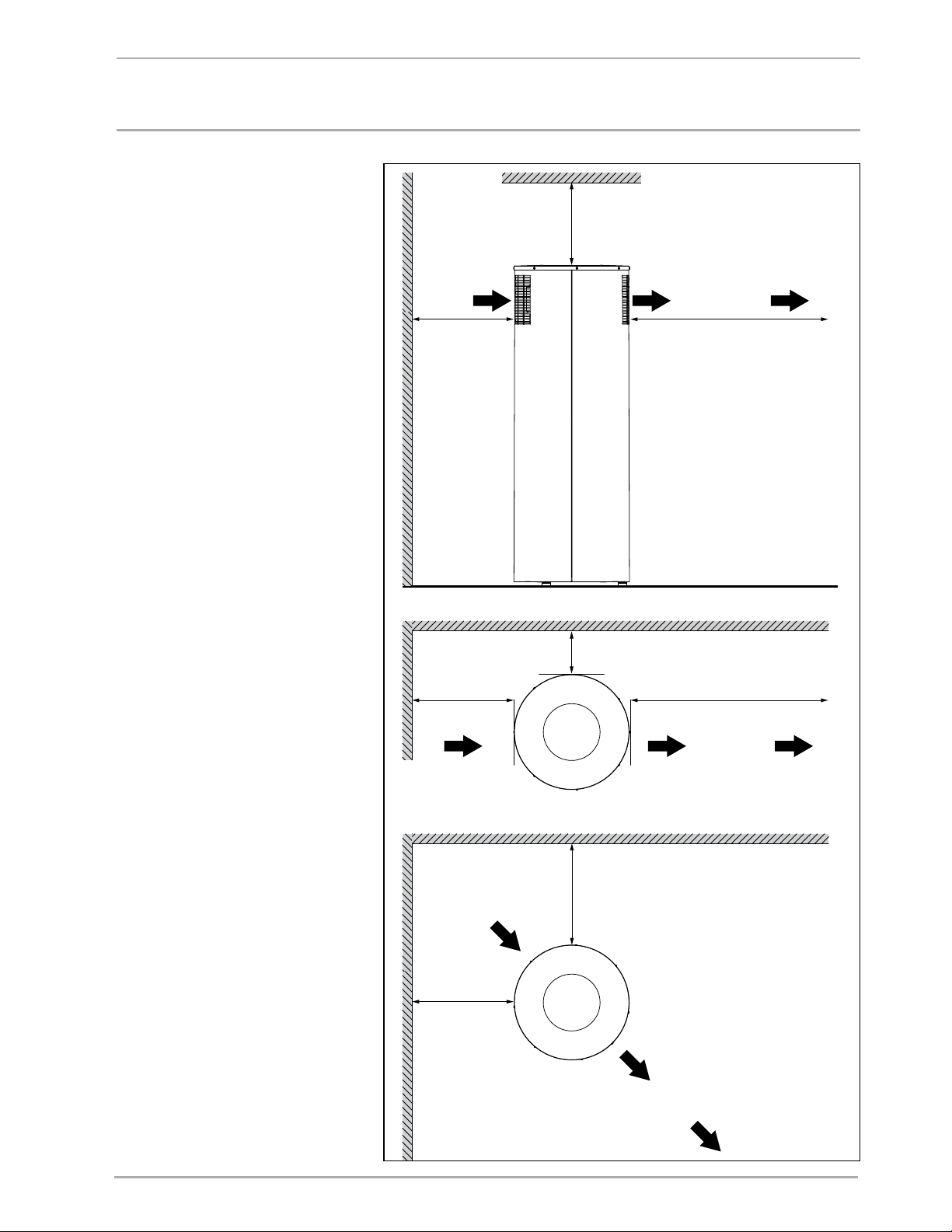
› Do not install in a room with
less than 800 cubic feet of
total volume (for example:
10 ft. x 10 ft. x 8 ft.).
› Do not install with the air
exhaust pointing at a wall
or any surface closer than 6
feet away.
› Do not install with the air
intake pointing to a wall or
any surface closer than 2
feet away.
Failure to follow installation
instructions will void the
factory warranty.
Page 4
ENGLISH
WWW.STIEBEL-ELTRON-USA.COM ACCELERA 300 | 4
QUICK START-UP GUIDE | OPERATION
HMC
Cold water
Hot water
2
12
15
13
14
11
3
4
5
6
7
8
9
10
1
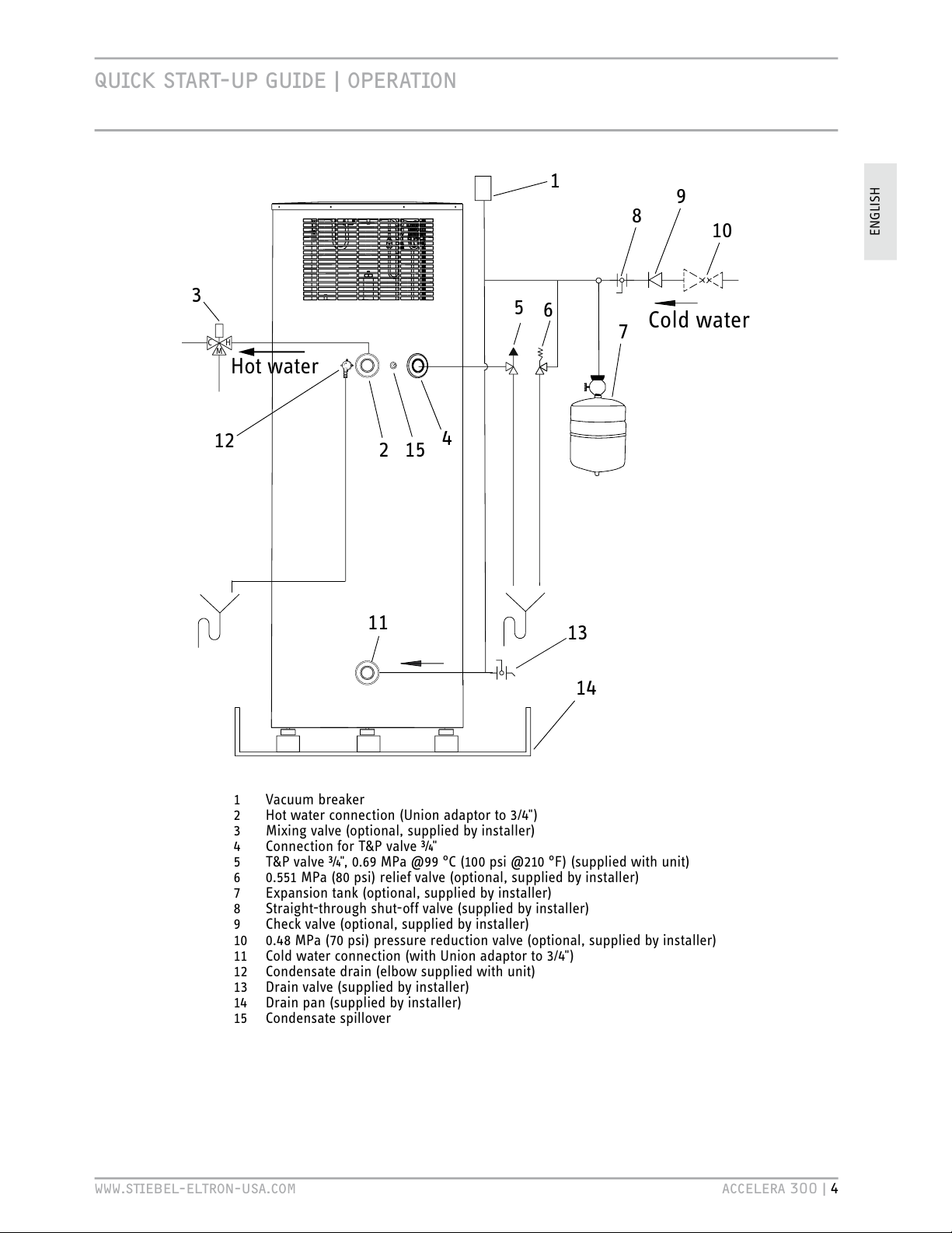
1 Vacuum breaker
2 Hot water connection (Union adaptor to 3/4")
3 Mixing valve (optional, supplied by installer)
4 Connection for T&P valve ¾"
5 T&P valve ¾", 0.69 MPa @99 °C (100 psi @210 °F) (supplied with unit)
6 0.551 MPa (80 psi) relief valve (optional, supplied by installer)
7 Expansion tank (optional, supplied by installer)
8 Straight-through shut-off valve (supplied by installer)
9 Check valve (optional, supplied by installer)
10
0.48 MPa (70 psi) pressure reduction valve (optional, supplied by installer)
11
Cold water connection (with Union adaptor to 3/4")
12 Condensate drain (elbow supplied with unit)
13 Drain valve (supplied by installer)
14
Drain pan (supplied by installer)
15 Condensate spillover
Page 5

ENGLISH
WWW.STIEBEL-ELTRON-USA.COM ACCELERA® 300 HEAT PUMP WATER HEATER | 5
CONTENTS | OPERATION
GENERAL INFORMATION ____________________________________________2
QUICK START-UP GUIDE ____________________________________________2
OPERATION __________________________________________________________5
1. Overview ____________________________________________________5
2. General information ________________________________________5
2.1. Key to symbols ___________________________________________________ 5
3. Safety ________________________________________________________9
3.1. General safety instructions ____________________________________ 9
3.2. Intended use ______________________________________________________ 9
3.3. Incorrect use ______________________________________________________ 9
3.4. Personnel qualification _________________________________________ 9
3.5. Safety equipment ________________________________________________ 9
3.6. Particular risks ___________________________________________________ 9
4. Water heater description _________________________________ 10
4.1. Function description ___________________________________________10
5. Operation __________________________________________________ 10
5.1. Initial start-up by a licensed installer ______________________10
5.2. Starting and stopping __________________________________________10
5.3. Emergency stop _________________________________________________10
6. Maintenance and care ____________________________________ 10
6.1. Descaling _________________________________________________________11
7. What to do if ... ___________________________________________ 11
7.1. ... the water heater does not deliver hot water ___________ 11
7.2 . ... the safety valve of the cold water supply line is
dripping __________________________________________________________ 11
7.3 . ... the condensate drain drips ________________________________ 11
7.4 . ... the power consumption is too high ______________________11
7.5. ... the room temperature drops excessively _______________11
7.6 . ... other faults occur ____________________________________________11
8. Safety ______________________________________________________ 11
8.1. General safety instructions ___________________________________ 11
8.2. Incorrect use _____________________________________________________12
8.3. Qualification _____________________________________________________ 12
8.4. Instructions, standards and regulations ___________________12
8.5. Water installation _______________________________________________ 12
8.6. Electrical installation___________________________________________ 12
9. Water heater description _________________________________ 12
9.1. Standard delivery _______________________________________________ 13
9.2. Special accessories _____________________________________________ 13
10. Installation ________________________________________________ 13
10.1. Installation location ____________________________________________13
10.2. Shipping inspection ____________________________________________14
10.3. Handling __________________________________________________________ 14
10.4. Storage ____________________________________________________________ 14
10.5. Positioning the water heater _________________________________14
10.6. Unpacking the water heater __________________________________14
10.7. Water connection _______________________________________________17
10.8. Power supply: 240V / 15A double pole circuit breaker __ 17
11. Initial start-up ____________________________________________ 19
11.1. Initial start-up ___________________________________________________ 19
11.2. Shutting down ___________________________________________________ 19
11.3. Restarting ________________________________________________________ 19
12. Settings ____________________________________________________ 19
12.1. Adjusting the water temperature ____________________________ 19
13. Water heater hand over __________________________________ 19
14. Troubleshooting ___________________________________________ 19
14.1. Safety equipment of the water heater ______________________ 19
14.2. Troubleshooting _________________________________________________20
15. Maintenance and cleaning _______________________________ 20
15.1. Cleaning the evaporator ______________________________________ 20
15.2. Draining the tank _______________________________________________20
15.3. Sacrificial anode rod ___________________________________________20
15.4. Descaling _________________________________________________________20
15.5. Checking valves _________________________________________________21
16. Specification _______________________________________________ 21
16.1. Connection and dimensions __________________________________21
16.2. Wiring diagram _________________________________________________22
16.3.
Refrigerant diagram ___________________________________________23
16.4. Technical Data ___________________________________________________ 24
WARRANTY ________________________________________________________ 27
ENVIRONMENT AND RECYCLING _________________________________ 27
Page 6
OPERATION
OvER
vIEW
6 | ACCELERA® 300 HEAT PUMP WATER HEATER WWW.STIEBEL-ELTRON-USA.COM
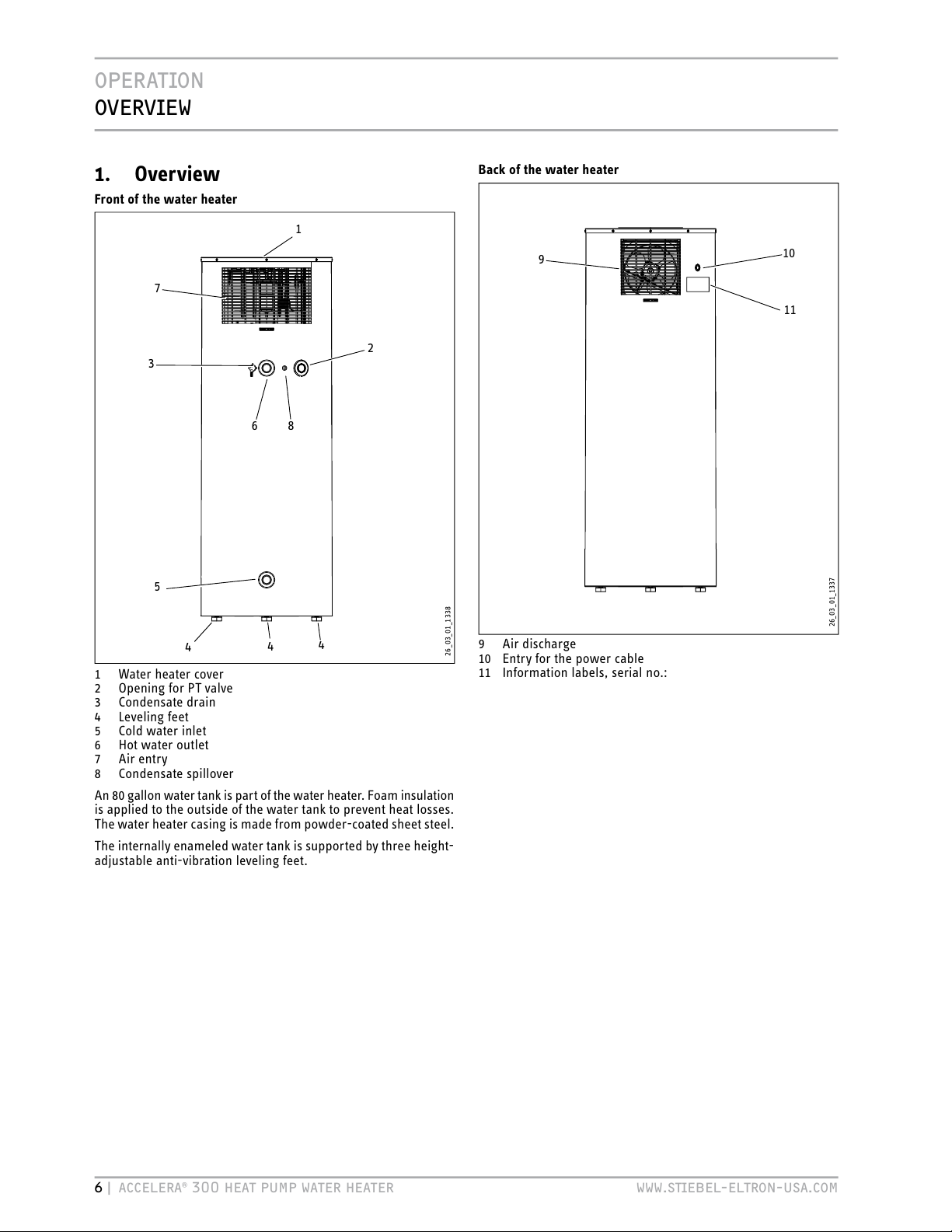
1. Overview
Front of the water heater
7
6
2
5
4
3
1
26_03_ 01_1338
4
4
8
1 Water heater cover
2 Opening for PT valve
3 Condensate drain
4 Leveling feet
5 Cold water inlet
6 Hot water outlet
7 Air entry
8 Condensate spillover
An 80 gallon water tank is part of the water heater. Foam insulation
is applied to the outside of the water tank to prevent heat losses.
The water heater casing is made from powder-coated sheet steel.
The internally enameled water tank is supported by three height-
adjustable anti-vibration leveling feet.
Back of the water heater
9
10
26_03_ 01_1337
9 Air discharge
10 Entry for the power cable
11
Information labels, serial no.:
11
Page 7

OPERATION
GENERAL
INFORMATION
ENGLISH
WWW.STIEBEL-ELTRON-USA.COM ACCELERA® 300 HEAT PUMP WATER HEATER | 7
2. General information
The chapter Operation is intende d for users and licens ed installers .
The chapter Installation is intended for licensed installers only.
2.1 Key to symbols
2.1.1 Layout of safety information
DANGER Electric shock
Before any work on the water heater,
disconnect all poles from the power
supply.
1
3
4
2
1 Symbol (see chapter "Symbols")
2 Keyword (see chapter "Keywords")
3 Designations (see chapter "Symbols")
4 Information text
2.1.2 Symbols
Symbol Description
Injury
Electrocution
Burns or scalding
!
Other situations
Fire
Explosion
Water heater disposal
2.1.3 Keywords
KEYWORD
DANGER
The keyword DANGER indicates information
that must be observed, otherwise serious injury
or death
will result.
WARNING
The keyword WARNING indicates information
that must be observed, otherwise serious injury
or death
may result.
CAUTION The keyword CAUTION indicates information
that must be observed, otherwise relatively
serious or light injuries may result.
2.1.4 Symbols in this documentation
Read the text next to this symbol carefully.
» Passages with the symbol "»" indicate that you have to do
something. The action you need to take is described step by
step.
- Passages with this symbol "–" indicate lists.
2.1.5 Units of measure in this documentation
The dimensions in this document are given in
millimeters (inches).
2.1.6 Information on the packaging
Information label "Top heavy"
! !
Hoher Schwerpunkt
High balance point
Hoog zwaartepunt
Centre de gravité en partie haute
Hög tyngdpunkt
Alto centro di graviá
Alto centro de gravedad
Achtung - Attention - Attentie - Attention
Uppmärksamhet - Oppmerksomhet
Attenzione - Atención
264623-33631
Information label "Vertical transport"
!CHTUNG!TTENTION
4RANSP ORTUN D!UFS TELLUN G
$AMITDAS'ERËTVOR"ESCHËDIGUNGENGESCHàTZTISTSOLLTEESBISANDEN-ONTAGEORTINDER6ERPACKUNGTRANSPORTIERTWERDEN
'ERËTSENKRECHTTRANSPORTIEREN"EI
BEENGTEN4RANSPORTBEDINGUNGENKANNDAS'ERËTAUCHKURZZEITIGGENEIGTWERDEN"EACHTEN3IEDIEWEITEREN(INWEISEZUM!UFSTELLENUND!USRICHTENDES'ERË
TESINDERBEILIEGENDEN'EBRAUCHSUN D-ONTAGEANWEISUNGUM3CHËDENAM'ERËTZUVER MEIDEN
4RANSP ORTAN DINS TALLAT ION
4OPR OTEC TTH EEQ UIPM ENT AGAI NST DAMAG EIT MUS TBE TRA NSPO RTED INS IDE ITS DEDIC ATED PAC KAGI NGU NTIL THE INS TALL ATIO NFA CILI TYI SAR RIVED
4RANSP ORTTH EEQU IPMENT
UPRIGHT
7HERESPACEISRESTRICTEDYOUMAYALSOMOVEBRIEFLYTHEEQUIPMENTTIPPEDBACKWARDSATANANGLE/BSERVETHENOTESONINSTALLATIONANDFITTINGOFTHE
EQUIPMENTWHICHCANBEFOUNDINTHEENCLOSEDINSTALLATIONANDOPERATINGINSTRUCTIONSTOAVOIDPOSSIBLEDAMAGETOTHEEQUIPMENT
'ERËTNURSENKRECHTODERGGFGENEIGTTRANSPORTIEREN
-OVETHISMACHINEONLYINAVERTICALPOSITIONORIFREQUIREDSLIGHTLYINCLINEDWITHTHECONTROLFACIAPOINTUP
280306-34594
Page 8
OPERATION
GENERAL
INFORMATION
8 | ACCELERA® 300 HEAT PUMP WATER HEATER WWW.STIEBEL-ELTRON-USA.COM
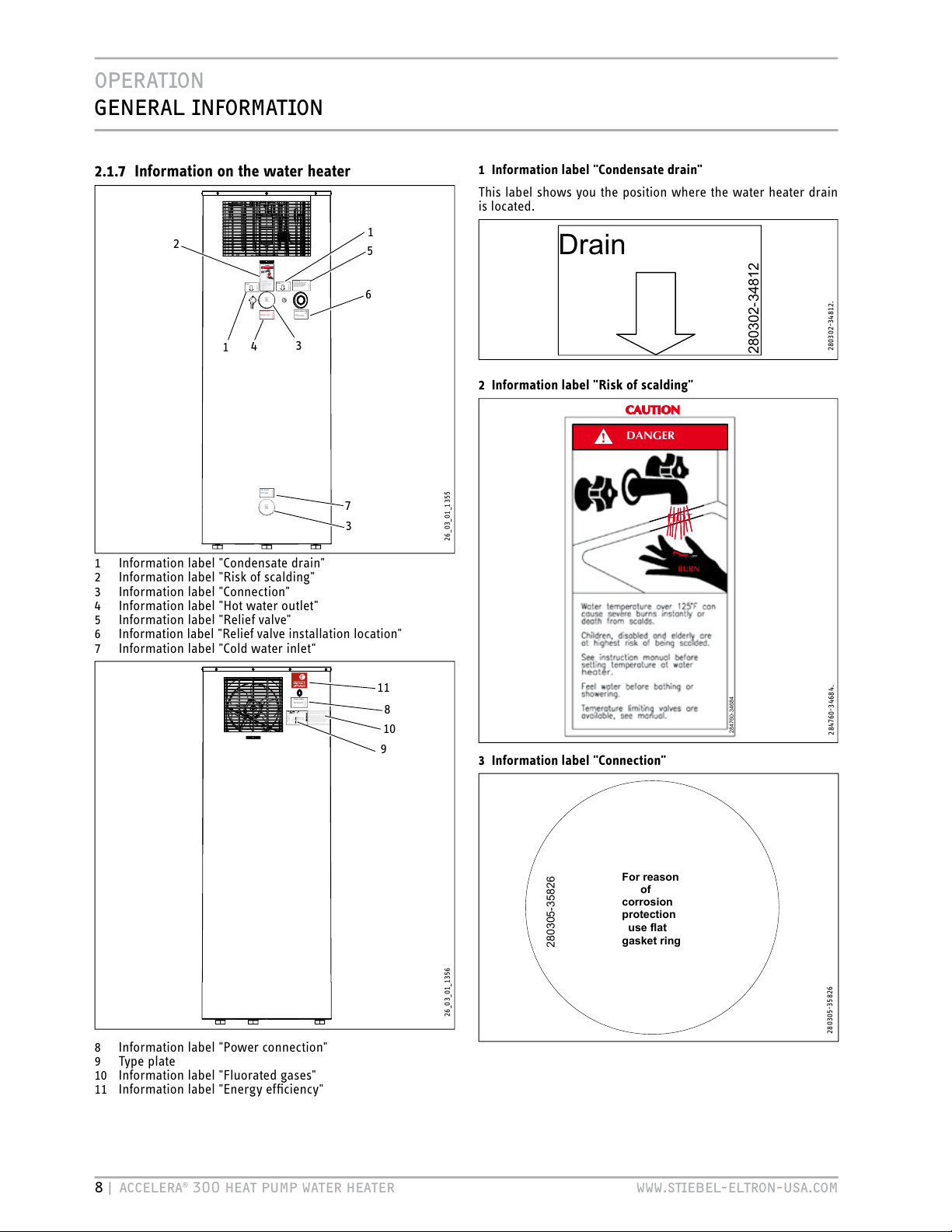
2.1.7 Information on the water heater
For reason
of
corrosion
protection
use flat
gasket ring
28030 5 - 35826
BURN
HOT
CAUTION
DANGER
!
284760-34684
WW Austritt
DHW outlet
2
803
0
4
-34
6845
Warning
A temperature and pressure relief valve
must be fitted to the clearly marked
socket. The valve drain outlet pipe
must not be sealed or blocked, and the
valve easy gear is to be operated
at least once every six month.
28
0
5
58-
34684
Drain
28
0
3
0
2-3481284594
KW Eintritt
CW Inlet
2
80303
-
3
46845
For reason
of
corrosion
protection
use flat
gasket ring
28030 5 - 35826
Drain
28
0
3
0
2-3481284594
Relief valve
Plumber:
The relief valve installation
must be fitted to this socket.
280557-35826
2
4
6
1
7
3
5
26_03_ 01_1355
3
1
1 Information label "Condensate drain"
2 Information label "Risk of scalding"
3 Information label "Connection"
4 Information label "Hot water outlet"
5 Information label "Relief valve"
6 Information label "Relief valve installation location"
7 Information label "Cold water inlet"
Power supply
Disconnect power supply
before opening the cover.
2
80
5
56-3
4
68425
Type: Accelera 300/WHP 300
Heat pump:
PN (Air 42° / Water 60°):
IN (Air 42° / Water 60°):
Type of Refrigerant:
Refrigerant charge:
Max. operating pressure:
Lock rotor current:
MCA:
Rated load compressor:
Motor fan:
Order-No.: 222423
DHW-cylinder:
Additional heating element:
Max. operating pressure:
Max. operating temperature:
Type of cylinder material:
Cylinder capacity:
Test pressure storage tank:
Observe the installation manual! Tested for leaks!
Made in Germany
No.: 8443 / 005204
Voltage / Frequency:
Breaker:
P (rated power input):
Maximum allowable ratings
Protection class:
Nmax
Single phase 220-240 V, 50/60 Hz
15 amp.
2200 W, 9.17 A
IP 24
*222423844300520415*
1690 W
87 psi /600
kPa
168.8 °F /76 °C
Glass lined steel
80.044 Gal /303 l
130.5 psi / 900 kPa
0.5 kW
2.17 A
R134A
1.9842 Lb. /900 g
348.1 psi /2.4 MPa
13.4 A
10.4 A
2.3 A
38 W
STIEBEL ELTRON INC
17 West Street
West Hatfield, MA 01088
USA
282209-35237
DE: Enthält vom Kyoto - Protokoll erfasste fluorierte Treibhausgase - hermetisch geschlossenes System.
GB: Contains fluorinated greenhouse gases covered by the Kyoto Protocol - hermetically sealed.
FR: Comprend les gaz à effet de serre fluorés enregistrés par le protocole de Kyoto - systèmes hermétiquement scellés.
NL: Bevat gefluoreerde broeikasgassen die onder het Kyoto-protocol vallen - hermetisch gesloten systeem.
SE: Innehåller av Kyoto - protokollet registrerade flourerande växthusgaser i hermetiskt förslutna system.
PL: Zawiera fluorowane gazy cieplarniane ujęte w Protokole z Kioto - hermetycznie zamknięty układ.
CZ: Obsahuje fluorizované skleníkové plyny, obsažené v Kjótském protokolu - hermeticky uzavřený systém.
ES: Sistema herméticamente cerrado que contiene gases de efecto invernadero mencionados en el protocolo de Kioto.
DK: Indeholder fra Kyoto-protokollen registrerede, fluorerede drivhusgasser – hermetisk lukket system.
NO: Inneholder fluorerte drivhusgasser som omfattes av Kyotoprotokollen - hermetisk lukket system.
FI: Sisältää Kioton sopimuksen alaisia fluorattuja kasvihuonekaasuja - ilmatiiviisti suljettu järjestelmä.
284436-34741
BG: Съдържа посочените в Протокола от Киото флуорирани парникови газове - херметически затворена система.
HU: A Kiotói Jegyzıkönyv szerinti fluortartalmú üvegházhatású gázokat tartalmaz - hermetikusan zárt rendszer.
IT: Contiene gas fluorurati ad effetto serra disciplinati dal protocollo di Kyoto - Impianto ermeticamente chius.
RO: Conține un sistem închis ermetic contra emisiei de gaze fluorine monitorizat de protocolul Kyoto.
8
11
26_03_ 01_1356
10
9
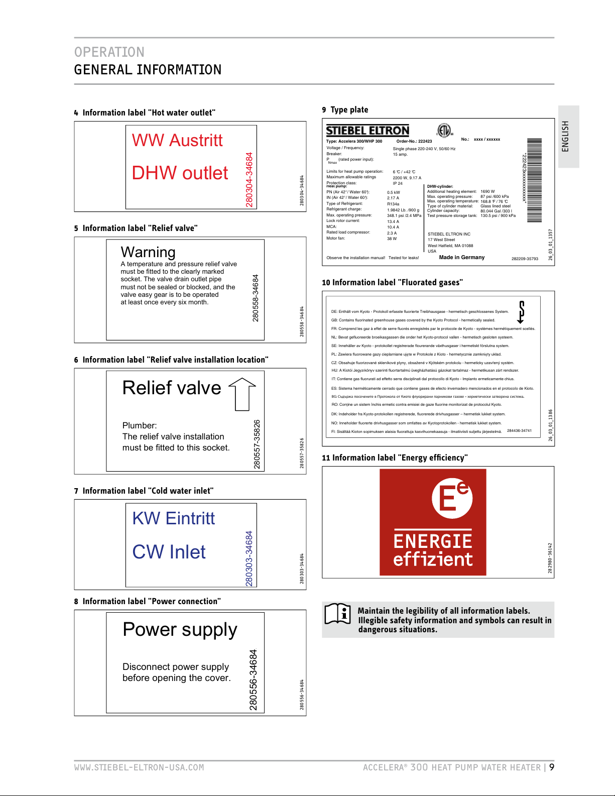
8 Information label "Power connection"
9 Type plate
10
Information label "Fluorated gases"
11
Information label "Energy efficiency"
1 Information label "Condensate drain"
This label shows you the position where the water heater drain
is located.
Drain
280302-3481284594
280302-34812.
2 Information label "Risk of scalding"
BURN
HOT
CAUTION
DANGER
!
284760-34684
284760-34684.
3 Information label "Connection"
For reason
of
corrosion
protection
use flat
gasket ring
28030 5 - 35826
280305-35826
Page 9
OPERATION
GENERAL
INFORMATION
ENGLISH
WWW.STIEBEL-ELTRON-USA.COM ACCELERA® 300 HEAT PUMP WATER HEATER | 9
4 Information label "Hot water outlet"
WW Austritt
D
HW outlet
280304-346845
280304-34684
5 Information label "Relief valve"
Warning
A
temperature and pressure relief valve
m
ust be fitted to the clearly marked
s
ocket. The valve drain outlet pipe
m
ust not be sealed or blocked, and the
v
alve easy gear is to be operated
a
t least once every six month.
280558-34684
280558-34684
6
Information label "Relief valve installation location"
R
elief valve
P
lumber:
T
he relief valve installation
m
ust be fitted to this socket.
280557-35826
280557-35826
7 Information label "Cold water inlet"
K
W Eintritt
C
W Inlet
280303-346845
280303-34684
8 Information label "Power connection"
Power supply
D
isconnect power supply
b
efore opening the cover.
280556-3468425
280556-34684
9 Type plate
Type: Accelera 300/WHP 300
Heat pump:
PN (Air 42° / Water 60°):
IN (Air 42° / Water 60°):
Type of Refrigerant:
Refrigerant charge:
Max. operating pressure:
Lock rotor current:
MCA:
Rated load compressor:
Motor fan:
Order-No.:
222423
DHW-cylinder:
Additional heating element:
Max. operating pressure:
Max. operating temperature:
Type of cylinder material:
Cylinder capacity:
Test pressure storage tank:
Observe the installation manual! Tested for leaks!
Made in Germany
No.: xxxx / xxxxxx
Voltage / Frequency:
Breaker:
P (rated power input):
Limits for heat pump operation
:
Maximum allowable ratings
Protection class:
Nmax
Single phase 220-240 V, 50/60 Hz
15 amp.
6 °C / +42 °C
2200 W, 9.17 A
IP 24
*222423xxxxxxxxxxxx*
1690 W
87 psi /
600 kPa
168.8 °F /
76
°C
Glass lined steel
80.044 Gal /303 l
130.5 psi / 900 kPa
0.5
kW
2.17
A
R134a
1.9842 Lb. /900 g
348.1 psi /2.4
MPa
13.4 A
10.4 A
2.3 A
38 W
STIEBEL ELTRON INC
17 West Street
West Hatfield, MA 01088
USA
282209
-35793
26_03_ 01_1357
10 Information label "Fluorated gases"
DE: Enthält vom Kyoto - Protokoll erfasste fluorierte Treibhausgase - herm etisch geschlossenes System.
GB: Contains fluorinated greenhouse gases covered by the Kyoto Protocol - herm etically sealed.
FR: Comprend les gaz à effet de serre fluorés enregistrés par le pro tocole de Kyoto - systèmes hermétiquement scellés.
NL: Bevat gefluoreerde broeikasgassen die onder het Kyoto-protocol vallen - hermetisch gesloten systeem.
SE: Innehåller av Kyoto - protokollet registrerade flourerande växthusgase r i hermetiskt förslutna system.
PL: Zawiera fluorowane gazy cieplarniane ujęte w Protokole z Kioto - hermetycznie zamknięty układ.
CZ: Obsahuje fluorizované skleníkové plyny, obsažené v Kjótském protokolu - her meticky uzavřený systém.
ES: Sistema herméticamente cerrado que contiene gases de efecto invernadero mencionados en el protocolo de Kioto.
DK: Indeholder fra Kyoto-protokollen registrerede, fluorerede drivhusgasser – hermetisk lukket system.
NO: Inneholder fluorerte drivhusgasser som omfattes av Kyotoprot okollen - hermetisk lukket system.
FI: Sisältää Kioton sopimuksen alaisia fluorattuja kasvihuonekaasuja - ilmatiiviisti suljettu järjeste lmä.
284436-34741
BG: Съдържа посочените в Протокола от Киото флуорирани парникови газове - херметически затворена система.
HU: A Kiotói Jegyzıkönyv szerinti fluortartalmú üvegházhatású gázokat tartalmaz - hermetikusan zárt rendszer.
IT: Contiene gas fluorurati ad effetto serra disciplinati dal protocollo di Kyoto - Impianto ermeticamente chius.
RO: Conține un sistem închis ermetic contra emisiei de gaze fluorine monitorizat de protocolul Kyoto.
26_03_ 01_1386
11 Information label "Energy efficiency"
282980-36142
Maintain the legibility of all information labels.
Illegible safety information and symbols can result in
dangerous situations.
Page 10

OPERATION
SAFETY
10 | ACCELERA® 300 HEAT PUMP WATER HEATER WWW.STIEBEL-ELTRON-USA.COM
3. Safety
This chapter provides an overview of all important actions required
for a safe and trouble-free operation.
3.1 General safety instructions
Operate the water heater only when fully installed and with all
safety equipment in place.
Unsuitable tools or incorrect handling can result in damage to
the water heater.
DANGER Scalding
The water is heated inside the water tank to60 °C
(140 °F). There is a risk of scalding at outlet
temperatures above 43 °C (109 °F).
» Ensure that outflowing water does not directly
contact your body.
CAUTION Injury
Where children or persons with limited physical,
sensory or mental capabilities are allowed to control
this water heater, ensure that this will only happen
under supervision or after appropriate instruction by
a person responsible for their safety.
» Children should be supervised to ensure that they
never play with the water heater.
Never place any objects on top of the water heater.
Objects placed on top of the water heater can increase
the noise level developed by the water heater through
vibrations.
Never cover the water heater.
The water heater draws in air. Covering the inlet slots
reduces the air intake. This reduces the efficiency of
the water heater and can even lead to one of the safety
devices interrupting the water heater operation.
3.2 Intended use
This water heater produces hot water automatically.
The water heater can be installed and operated in the open as well
as in enclosed spaces. The temperature of the air that is drawn in
during operation must not fall below 6 °C (43 °F).
Any other use beyond that described shall be deemed inappropriate.
Observation of these instructions is also part of the correct use of
this water heater.
Any changes or modifications to this water heater void all warranty
rights.
3.3 Incorrect use
The following are not permitted:
- Do not heat anything other than potable water
- Do not use unqualified (unlicensed) personnel for installation
- Do not use in an environment with greasy extract air
This water heater must not be operated at ambient
temperatures in excess of 42 °C (107 °F) or below 6 °C
(43 °F).
If outside air is directly drawn in ensure, that the
water heater is isolated from its power supply when
the air temperature falls below 6 °C (43 °F).
3.4 Personnel qualification
DANGER Injury
Incorrect handling can result in severe injuries and
material losses. Inadequately qualified personnel
cannot assess the potential risks.
Have the installation, initial start-up, maintenance
and repair steps carried out only by the qualified
individuals specified in the respective chapters.
In the remainder of this manual, such qualified individuals will be
described as the "licensed installer."
3.5 Safety equipment
Wear safety shoes/boots during the transportation and positioning
of the water heater. Dry, this water heater weighs 130 kg (290 lb).
Safety shoes/boots reduce the risk of injury.
3.6 Particular risks
3.6.1 Electric current
WARNING Electric shock
Contacting parts that carry live power is associated
with a direct risk to life. Damaging the insulation or
individual components can result in a risk to life.
» If you detect damaged insulation, immediately
switch off the power supply and arrange for the
necessary repair.
» Have all electrical work carried out by a qualified
electrician.
3.6.2 Hot surfaces
CAUTION Burning
Contact with hot components can result in burning.
» When working near hot components, wear
protective clothing and gloves.
» The pipework connected to the hot water outlet of
the water heater can reach temperatures in excess
of 60 °C (140 °F).
3.6.3 Refrigerant
The water heater is filled with R134A refrigerant at the factory.
WARNING Freezer burn
Should the water heater leak refrigerant, avoid contact
with the refrigerant or breathing in any released
vapors. Immediately vent the room.
In normal water heater operation, the refrigerant is contained in
a sealed circuit.
Page 11
OPERATION
WATER HEATER DESCRIPTION
ENGLISH
WWW.STIEBEL-ELTRON-USA.COM ACCELERA® 300 HEAT PUMP WATER HEATER | 11
4. Water heater description
This water heater is an automatic hot water generator with approx.
303 l (80gallon) capacity. The hot water temperature is factory
set to 60 °C (140 °F).
After opening a hot water faucet, the hot water is pushed out of
the water heater by the incoming cold water.
This water heater works like an air conditioner but does not need
to be vented. The water heater extracts heat from the ambient air
to heat the water. The demand for electrical energy and the heatup time depend on the ambient air temperature and humidity.
When installing the water heater inside, the space where it is
installed will be cooled down during the operation by 1 to 3 °C
(2 to 6 °F).
The water heater also extracts moisture from the air that creates
condensate, which must be drained off. For this purpose, a
condensate drain is integrated in the water heater. This is where
you can connect a hose to a drain.
To protect the steel tank against corrosion, the interior is coated
with a special enamel and is equipped with a replaceable sacrificial
anode.
Heat pump function:
A sealed circuit inside the water heater contains R134A refrigerant
(see "Specification/data table"); this does not deplete ozone, is
non-flammable, and evaporates at low temperatures.
In the evaporator, where heat is extracted from the outside air,
the refrigerant changes from its liquid into its gaseous state. A
compressor draws in the gas in and compresses it. The increase
in pressure raises the refrigerant temperature and heats the water
tank.
This process requires electrical energy. The energy (motor heat)
is not lost, but reaches the condenser downstream together with
the compressed refrigerant. Here, the gas transfers heat to the
water tank. An expansion valve then reduces the pressure and
the process starts again.
4.1 Function description
4.1.1 Heat pump operation
The heat pump unit located on top of the water heater extracts
heating energy from the ambient air.
If the water heater was separated from the power
supply during operation, the compressor will only
restart if the pressure inside the refrigerant circuit has been
balanced. Pressure balance can only be created after waiting
15 minutes.
4.1.2 Booster heater
Primarily, the water inside the tank is heated by the heat pump.
When there is a higher hot water demand or when the water heater
was switched OFF and you require hot water quickly, the integral
booster heater will turn on. To save energy, the booster heater
only heats the top third of the tank (approx. 102 l (27 gallons)).
A thermostat switches the booster heater on if the water
temperature inside the tank falls below 45 °C (112 °F). A thermostat
switches the booster heater off if the water temperature inside the
tank exceeds 60 °C (140 °F).
4.1.3 Defrosting
The lower limit of use of the water heater is permanently set to
6 °C (42 °F). It is possible that at this limit, the evaporator will be
coated in frost. This is subject to the air temperature and humidity
level, particularly at low hot water temperatures.
The compressor will be switched off as soon as the evaporation
temperature falls below -7 °C (20 °F) for any length of time. When
the temperature at the evaporator fins rises above 3 °C (38°F), the
compressor starts again, and the hot water heating continues. The
fan continues to run during defrosting.
5. Operation
You do not have to make any adjustments. The water heater
is therefore not equipped with any controls. The hot water
temperature is factory set to 60 °C (140 °F).
Should you wish to operate with different settings, contact your
local licensed installer.
WARNING Scalding
The water is heated inside the water tank to
60 °C (140 °F). There is a risk of scalding at outlet
temperatures in excess of 42 °C (108 °F).
Ensure that outflowing water does not directly contact
your body.
5.1 Initial start-up by a licensed installer
Initial start-up should be done by a licensed installer.
5.2 Starting and stopping
The water heater is not equipped with an ON/OFF switch. If a
power plug was fitted during installation, you can disconnect
the water heater from the power supply by pulling that plug.
Alternatively, you can terminate the water heater operation by
tripping the circuit breaker.
5.3 Emergency stop
In case of emergency, carry out the following steps:
» Isolate the power supply by tripping the circuit breaker or by
pulling the power plug.
» Shut off the cold water inlet.
6. Maintenance and care
A damp cloth is sufficient for cleaning the exterior of the water
heater. Never use abrasive or corrosive cleaning agents. Do not
hose down the water heater.
» Monthly, check that the condensate drain is clear.
» Monthly, carry out a visual inspection of the condensate
pan drain (in the top of the water heater; see the following
diagram). Look through the air intake grille at the front of the
water heater. If required, notify your local licensed installer
who will remove any contamination.
Page 12

OPERATION
WHAT
TO DO IF ...
12 | ACCELERA® 300 HEAT PUMP WATER HEATER WWW.STIEBEL-ELTRON-USA.COM
1
26_03_ 01_1404
1 Condensate pan drain
6.1 Descaling
At high temperatures water separates out lime. This is deposited
on the inside of the tank. With increasing limescale build-up, the
amount of hot water inside the tank is reduced.
» Have a licensed installer descale the booster heater from
time to time. This extends the service life of the booster
heater.
» Scale cannot build up on the heat pump element.
A licensed installer who knows the local water quality will tell you
when the next maintenance appointment is due.
» Have your licensed installer check the sacrificial anode
regularly.
7. What to do if ...
7.1 ... the water heater does not deliver hot
water
» Check the water heater power supply.
» Check your fuse box for a tripped circuit breaker.
» Make sure there is a 15A double pole circuit breaker
If the circuit breaker has tripped, reset it or replace it. Notify your
local licensed installer if the circuit breaker trips again.
» Ensure that the air intake and air discharge are unobstructed.
Excessively high ambient temperature, excessively high
temperature of the air drawn in (>42 °C (108 °F)) or a fault in the
refrigerant circuit can result in the compressor being overloaded.
The thermal protective 'auto reset' motor switch or the high limit
'manual reset' cut-out can both shut off the compressor off.
The high limit pressure limiter must only be reset by
your licensed installer after they have removed the
cause of the relevant fault.
After a short cooling down period, the thermal protective motor
auto reset switch will restart the compressor automatically.
Notify your local licensed installer if the water heater does not
restart automatically.
7.2 ... the safety valve of the cold water supply
line is dripping
This unit can operate up to 0.48 MPa (70psi) of inlet pressure.
Expansion water drips from the safety valve during heat-up. This
is completely normal. Notify your local licensed installer if water
still drips after heat-up has been completed.
7.3 ... the condensate drain drips
This is quite normal and always happens when the surface
temperature of the evaporator is lower than the dew point
temperature of the ambient air.
7.4 ... the power consumption is too high
Please consult a qualified licensed installer.
7.5 ... the room temperature drops excessively
The water heater operation reduces the ambient air by
1 to 3 °C (2 to 6°F). Notify your local licensed installer if the
ambient temperature drops abnormally.
7.6 ... other faults occur
Notify your local licensed installer. Refer to the water heater
number on the type plate next to the barcode.
Type: Accelera 300/WHP 300
Heat pump:
PN (Air 42° / Water 60°):
IN (Air 42° / Water 60°):
Type of Refrigerant:
Refrigerant charge:
Max. operating pressure:
Lock rotor current:
MCA:
Rated load compressor:
Motor fan:
Order-No.:
222423
DHW-cylinder:
Additional heating element:
Max. operating pressure:
Max. operating temperature:
Type of cylinder material:
Cylinder capacity:
Test pressure storage tank:
Observe the installation manual! Tested for leaks!
Made in Germany
No.: xxxx / xxxxxx
Voltage / Frequency:
Breaker:
P (rated power input):
Limits for heat pump operation
:
Maximum allowable ratings
Protection class:
Nmax
Single phase 220-240 V, 50/60 Hz
15 amp.
6 °C / +42 °C
2200 W, 9.17 A
IP 24
*222423xxxxxxxxxxxx*
1690 W
87 psi /
600 kPa
168.8 °F /
76
°C
Glass lined steel
80.044 Gal /303 l
130.5 psi / 900 kPa
0.5
kW
2.17
A
R134a
1.9842 Lb. /900 g
348.1 psi /2.4
MPa
13.4 A
10.4 A
2.3 A
38 W
STIEBEL ELTRON INC
17 West Street
West Hatfield, MA 01088
USA
282209
-35793
26_03_ 01_1357
1
1 Water heater number
8. Safety
Only qualified licensed installers should carry out installation,
initial start-up, maintenance and repair of the water heater.
8.1 General safety instructions
Use only original accessories and spare parts intended for this
water heater.
DANGER Electric shock
Disconnect the water heater from the power supply
prior to its installation.
WARNING Injury
If the pipes inside the water heater are damaged,
leaking refrigerant gas can result in severe physical
freezer burns.
Do not inhale refrigerant. Immediately vent the room
thoroughly.
» Wear safety goggles and gloves during water heater
installation.
Page 13

OPERATION
WATER
HEATER DESCRIPTION
ENGLISH
WWW.STIEBEL-ELTRON-USA.COM ACCELERA® 300 HEAT PUMP WATER HEATER | 13
WARNING Injury
Moving parts represent a risk of injury.
» Before opening the water heater, ensure that the fan
has come to a complete standstill.
8.2 Incorrect use
The following are not permitted:
- Do not install the water heater on non-load bearing floors
- Do not install the water heater where it is at risk from frost
- Do not install in rooms where the water heater is at risk from
explosions as a result of dust, gases or vapors
- Do not ignore safety clearances and safety zones
- Do not incorrectly install the power connection
- Do not operate the water heater with the tank empty
- Do not operate the water heater with an open casing
- Do not heat anything other than potable water
- Do not fill with any other Freon, use only R134A
8.3 Qualification
WARNING Injury
Incorrect handling can result in severe injuries and
material losses. Inadequately qualified personnel
cannot assess the impending danger.
Have only personnel mentioned in the appropriate
sections of this manual carry out specific measures.
In this manual, such qualified individuals will be described as the
"licensed installer".
Licensed installers are responsible for adherence to all currently
applicable regulations during installation and initial start-up.
8.3.1 Licensed installer
Licensed installers are specially trained in their field. Licensed
installers work on systems on the basis of their training, knowledge
and experience, as well as their knowledge of applicable standards
and regulations. They are able on their own to recognize and
prevent possible problems.
8.3.2 Electrician (licensed)
An electrician is a licensed installer who meets the above
requirements with regard to electrical installations.
8.3.3 Plumber (licensed)
A plumber is a licensed installer who meets the above requirements
with regard to water-related installations.
8.3.4 Customer service
For customer service inquiries, please contact Stiebel Eltron
directly at 1-800-582-8423, ext. 25 or ext. 33.
8.4 Instructions, standards and regulations
Follow all national, state, and local codes.
Observe the regulations of your local energy and water supply
utilities.
The following standards were taken into account:
UL 499, UL 1995, UL 94-5 VA, UL 174
IEC 60335-1-2-40, IEC 61000-3-2; 1995
IEC 61000-3-3, IEC 55014-1 IEC 55014-2
EMC Directive 89/336/EEC
EN 255 T3
Read the water heater type plate and the chapter "Specification".
8.5 Water installation
The following materials may be used:
- Cold water line: steel, copper or plastic pipework.
- Hot water line: copper or plastic pipework.
» Ensure that no contamination reaches the water heater
through the pipework.
8.6 Electrical installation
Protect the water heater electrically with a 15A double pole circuit
breaker.
Where the water heater is permanently connected to the power
supply, it must be able to be separated from the mains power
supply by an additional isolator that disconnects all poles with
at least 3
mm (0.12") contact separation. For this purpose, use
contractors, circuit breakers, fuses, etc. on site.
In case of a fault, the safety equipment interrupts the relevant
power circuit.
9. Water heater description
3
2
1
4
5
26_03_ 02_1404
1 High limit safety cut-out - manual reset
2 Compressor
3 Condensate drain
4 Filter dryer
5 Service valve, high pressure
6 Sacrificial anode
6
Page 14
14 | ACCELERA® 300 HEAT PUMP WATER HEATER WWW.STIEBEL-ELTRON-USA.COM
INSTALLATION
INSTALLATION
8
7
9
10
26_03_ 02_1405
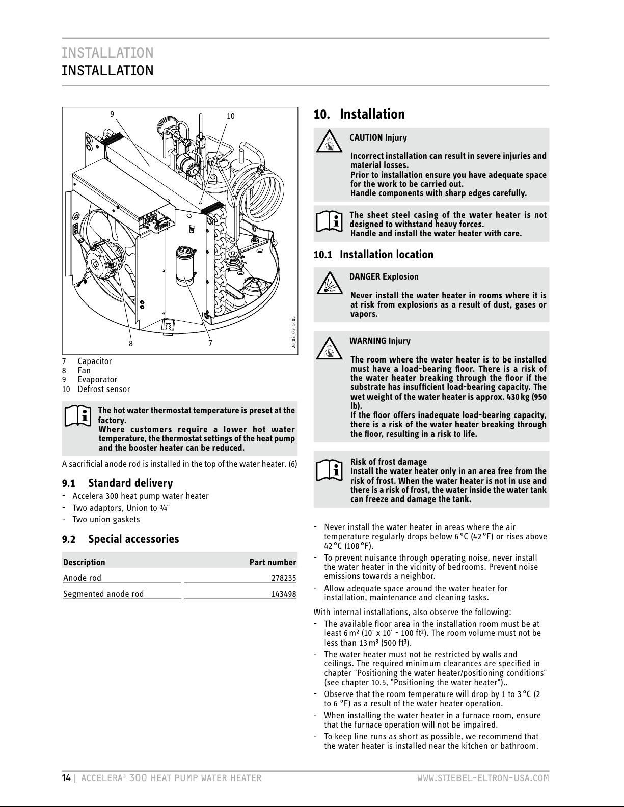
7 Capacitor
8 Fan
9 Evaporator
10 Defrost sensor
The hot water thermostat temperature is preset at the
factory.
Where customers require a lower hot water
temperature, the thermostat settings of the heat pump
and the booster heater can be reduced.
A sacrificial anode rod is installed in the top of the water heater. (6)
9.1 Standard delivery
- Accelera 300 heat pump water heater
- Two adaptors, Union to ¾"
- Two union gaskets
9.2 Special accessories
Description Part number
Anode rod 278235
Segmented anode rod 143498
10. Installation
CAUTION Injury
Incorrect installation can result in severe injuries and
material losses.
Prior to installation ensure you have adequate space
for the work to be carried out.
Handle components with sharp edges carefully.
The sheet steel casing of the water heater is not
designed to withstand heavy forces.
Handle and install the water heater with care.
10.1 Installation location
DANGER Explosion
Never install the water heater in rooms where it is
at risk from explosions as a result of dust, gases or
vapors.
WARNING Injury
The room where the water heater is to be installed
must have a load-bearing floor. There is a risk of
the water heater breaking through the floor if the
substrate has insufficient load-bearing capacity. The
wet weight of the water heater is approx. 430 kg (950
lb).
If the floor offers inadequate load-bearing capacity,
there is a risk of the water heater breaking through
the floor, resulting in a risk to life.
Risk of frost damage
Install the water heater only in an area free from the
risk of frost. When the water heater is not in use and
there is a risk of frost, the water inside the water tank
can freeze and damage the tank.
- Never install the water heater in areas where the air
temperature regularly drops below 6 °C (42 °F) or rises above
42
°C (108 °F).
- To prevent nuisance through operating noise, never install
the water heater in the vicinity of bedrooms. Prevent noise
emissions towards a neighbor.
- Allow adequate space around the water heater for
installation, maintenance and cleaning tasks.
With internal installations, also observe the following:
- The available floor area in the installation room must be at
least 6 m² (10' x 10' - 100 ft²). The room volume must not be
less than 13 m³ (500 ft³).
- The water heater must not be restricted by walls and
ceilings. The required minimum clearances are specified in
chapter "Positioning the water heater/positioning conditions"
(see chapter 10.5, "Positioning the water heater")..
- Observe that the room temperature will drop by 1to3 °C (2
to 6 °F) as a result of the water heater operation.
- When installing the water heater in a furnace room, ensure
that the furnace operation will not be impaired.
- To keep line runs as short as possible, we recommend that
the water heater is installed near the kitchen or bathroom.
Page 15

ENGLISH
WWW.STIEBEL-ELTRON-USA.COM ACCELERA® 300 HEAT PUMP WATER HEATER | 15
INSTALLATION
INSTALLATION
10.2 Shipping inspection
» Upon receipt, check your delivery for completeness and
possible transport damage.
If transport damage is visible, proceed as follows:
- Do not accept the delivery or only with reservations.
- Note down the extent of the damage on the shipping
documents or on the delivery note of the carrier.
- Initiate a complaint.
Immediately give notice of any damage.
Give notice of all damage as soon as it has been
identified. Claims can only be accepted within the
applicable claim period.
10.3 Handling
CAUTION Injury through heavy loads
Dry, this water heater weighs 130 kg (290 lb.). Use
suitable aids and sufficient personnel when handling
this water heater.
Risk of damage through incorrect handling.
Incorrect handling can result in substantial material
losses.
Observe the information on the packaging.
Remove the packaging just before the installation.
Risk of damage through overturning.
The water heater has a high centre of gravity and a
low overturning moment. Protect the water heater
against overturning.
Only position the water heater on a level substrate.
To protect the water heater against damage, it should be
transported vertically inside its packaging. Where space is
restricted, you can also tilt (max. 45°) the water heater briefly
to move it.
10.4 Storage
Where it is necessary to store the water heater prior to installation
for a longer period, observe the following:
- If possible, store the water heater in a dry and dust-free
ambience.
- Prevent the water heater from coming into contact with
aggressive materials.
- Prevent the water heater from being exposed to shocks or
vibrations.
- In case of prolonged storage, check the condition of the
water heater and its packaging regularly.
10.5 Positioning the water heater
» Position the water heater with its wooden pallet at the final
installation location in a 10’ x 10’ x 8’ area.
Install the water heater so that there is an adequate clearance
adjacent to the air grilles (see the following diagrams).
10.5.1 Installation conditions
It is important for water heater performance and to avoid damage
to adjacent surfaces that adequate clearance remains available
on the air flow intake (min. 2') and air flow exhaust sides (min
6') of the unit.
It is important for water heater maintenance that adequate space
remains available above the water heater.
15
2´
8
´
Air flow
intake
Air flow
intake
Air flow
exhaust
Air flow
exhaust
2´
2´
2´
Air flow
intake
Air flow
exhaust
´
2
´´ x 8´
D0000018502
» Level the water heater horizontally by adjusting the feet.
10.6 Unpacking the water heater
Ensure that the casing material in the lower section
will not be damaged.
Advice - The longer you keep the packaging foil
wrapped around the water heater, the longer it will
be protected against damage.
» Remove the packaging straps.
Page 16
16 | ACCELERA® 300 HEAT PUMP WATER HEATER WWW.STIEBEL-ELTRON-USA.COM
INSTALLATION
INSTALLATION
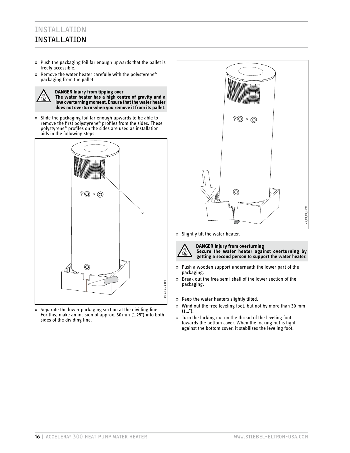
» Push the packaging foil far enough upwards that the pallet is
freely accessible.
» Remove the water heater carefully with the polystyrene
®
packaging from the pallet.
DANGER Injury from tipping over
The water heater has a high centre of gravity and a
low overturning moment. Ensure that the water heater
does not overturn when you remove it from its pallet.
» Slide the packaging foil far enough upwards to be able to
remove the first polystyrene
®
profiles from the sides. These
polystyrene® profiles on the sides are used as installation
aids in the following steps.
26_03_ 01_1395
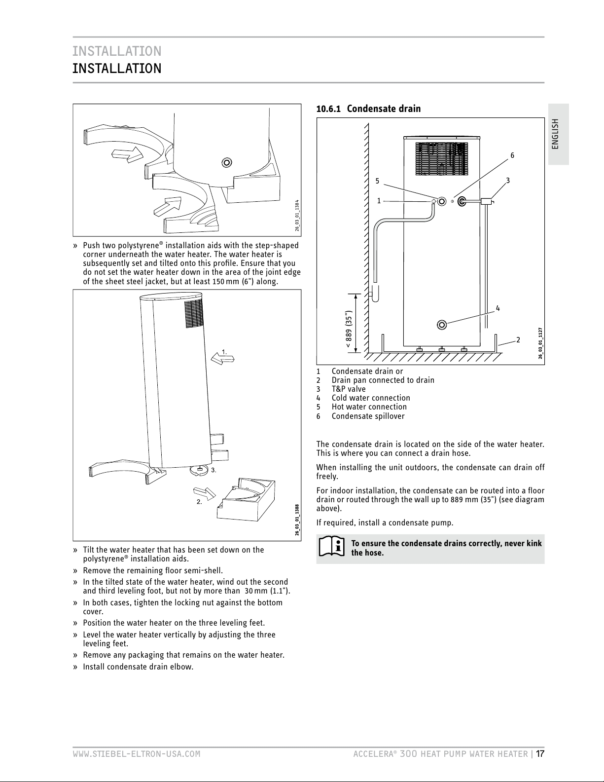
» Separate the lower packaging section at the dividing line.
For this, make an incision of approx. 30 mm (1.25") into both
sides of the dividing line.
6
26_03_ 01_1396
» Slightly tilt the water heater.
DANGER Injury from overturning
Secure the water heater against overturning by
getting a second person to support the water heater.
» Push a wooden support underneath the lower part of the
packaging.
» Break out the free semi-shell of the lower section of the
packaging.
» Keep the water heaters slightly tilted.
» Wind out the free leveling foot, but not by more than 30mm
(1.1").
» Turn the locking nut on the thread of the leveling foot
towards the bottom cover. When the locking nut is tight
against the bottom cover, it stabilizes the leveling foot.
Page 17
ENGLISH
WWW.STIEBEL-ELTRON-USA.COM ACCELERA® 300 HEAT PUMP WATER HEATER | 17
INSTALLATION
INSTALLATION
26_03_ 01_1384
» Push two polystyrene® installation aids with the step-shaped
corner underneath the water heater. The water heater is
subsequently set and tilted onto this profile. Ensure that you
do not set the water heater down in the area of the joint edge
of the sheet steel jacket, but at least 150 mm (6") along.
26_03_01_1388
» Tilt the water heater that has been set down on the
polystyrene® installation aids.
» Remove the remaining floor semi-shell.
» In the tilted state of the water heater, wind out the second
and third leveling foot, but not by more than 30 mm (1.1").
» In both cases, tighten the locking nut against the bottom
cover.
» Position the water heater on the three leveling feet.
» Level the water heater vertically by adjusting the three
leveling feet.
» Remove any packaging that remains on the water heater.
» Install condensate drain elbow.
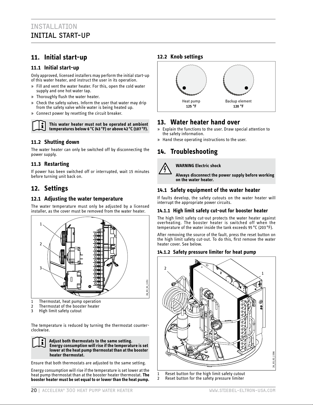
10.6.1 Condensate drain
26_03_01_1127
1
< 889 (35")
2
3
4
5
6
1 Condensate drain or
2 Drain pan connected to drain
3 T&P valve
4 Cold water connection
5 Hot water connection
6 Condensate spillover
The condensate drain is located on the side of the water heater.
This is where you can connect a drain hose.
When installing the unit outdoors, the condensate can drain off
freely.
For indoor installation, the condensate can be routed into a floor
drain or routed through the wall up to 889mm (35") (see diagram
above).
If required, install a condensate pump.
To ensure the condensate drains correctly, never kink
the hose.
Page 18

18 | ACCELERA® 300 HEAT PUMP WATER HEATER WWW.STIEBEL-ELTRON-USA.COM
INSTALLATION
INSTALLATION
10.7 Water connection
The water connection must be carried out by a qualified licensed
plumber.
The cold water connection must comply with DIN1988 [or state
and local codes]
» Prior to installing the water heater, flush the line thoroughly.
HMC
1
5
6
2
3
4
Cold water
7
8
9
10
Hot water
13
14
12
11
26_03_ 01_1123
15
1 Vacuum breaker
2 Hot water connection (Union adaptor to 3/4")
3 Mixing valve (optional, supplied by installer)
4 Connection for T&P valve ¾"
5 T&P valve ¾", 0.69 MPa @99 °C (100 psi @210 °F) (supplied
with unit)
6 0.551 MPa (80 psi) relief valve (optional, supplied by
installer)
7 Expansion tank (optional, supplied by installer)
8 Straight-through shut-off valve (supplied by installer)
9 Check valve (optional, supplied by installer)
10
0.48 MPa (70 psi) pressure reduction valve (optional,
supplied by installer)
11 Cold water connection (with Union adaptor to 3/4")
12
Condensate drain (elbow supplied with unit)
13 Drain valve (supplied by installer)
14 Drain pan (supplied by installer)
15 Condensate spillover
» Remove the protective rubber caps from the connectors.
» With a sharp knife, cut a hole into the protective caps and
install them over the pipe to be connected.
» Connect the plumbing.
» After connecting the plumbing, connect the protective caps
so that the sheet steel casing of the water heater grips into
the outer groove of the protective cap.
Risk of damage through corrosion
To protect against the risk of corrosion, make the
connection with flat gaskets.
» Insulate the hot water line against heat loss.
» Install a drain valve at the lowest point of the cold water
supply.
Install a 0.48 MPa (70 psi) pressure reducing valve on the cold
water inlet.
Accurately maintain the order of fittings on the cold water side
(see diagram 10.7).
10.7.1 Safety valve (on-site provision)
This water heater is a sealed unit. A 0.69MPa, 99°C (100psi,
210°F) T&P relief valve must be installed.
When installing the T&P valve, observe the following:
- Size the drain line so that water can drain off completely,
even if the safety valve is fully open.
- The drain outlet must not be able to be closed and must
always remain open to atmosphere.
- The T&P valve must open at a pressure of 0.69MPa (100 psi)
and be 3/4" pipe thread.
10.7.2 T&P valve (on-site provision)
WARNING Risk of injury through excessive pressure
and temperatures.
Install safety equipment that meets the applicable
regulations for the installation locations. In any case
install a "Pressure and Temperature Relief valve (T&P
relief)" that complies with the requirements of the
ANSIZ21.22 ("Requirements for Relief Valves and
Automatic Gas Shut-off Water heaters for Hot Water
Supply Systems").
The T&P valve must respond at a pressure of 0.69MPa
(100 psi). Fit the T&Pvalve into the opening on the
circumference of the water heater indicated.
Ensure that any expelled water cannot come into
contact with 'live' parts and will not run onto sensitive
surfaces. Ensure that the T&P valve outlet remains
free at all times.
10.8 Power supply: 240V / 15A double pole
circuit breaker
The electrical connection must be carried out by a qualified
electrician.
DANGER Electric shock
Contacting 'live' components results in a risk to life.
» Disconnect the water heater from the power supply
before carrying out work on the control panel.
» Be sure that no one can reconnect the power while
you are working.
When making a connection use code compliant disconnects.
» Undo the screws and remove the water heater cover.
Page 19

ENGLISH
WWW.STIEBEL-ELTRON-USA.COM ACCELERA® 300 HEAT PUMP WATER HEATER | 19
INSTALLATION
INSTALLATION
Air flow
→
Air flow
→
CAUTION :
Risk of electric shock
Use copper conductors only
11
10
4
6
3
1
16
15
13
12
8
7
14
9
5
26_03_ 01_1406
2
CAUTION :
Risk of electric shock
Use copper conductors only
1 Capacitor
2 Cable entry into the water heater casing
3 Strain relief (cable clamp)
4 Mains terminal
5 Frost monitor
6 Heat pump control thermostat
7 Fan motor
8 Heat pump terminal
9 Thermostat, booster heater
10
High limit safety cut-out, booster heater,
manual reset (see 14.1.1)
11
Booster heater
12 Sacrificial anode
13
Safety pressure limiter, manual reset,
(see 14.1.2)
14 Condensate pan drain
15
Compressor
16 Compressor motor protection (Klixon),
delay auto reset (see 14.1.3)
» Pull the power cable through the cable entry into the water
heater interior.
» Route the power cable through the strain relief (cable
clamp).
» Connect the power cable to the mains terminal in accordance
with the wiring diagram (see chapter 16.2 "Wiring Diagram".
L1, L2 and ground).
WARNING Electric shock
Risk of injury through inadequate grounding.
» Ensure that the water heater is correctly grounded
in accordance with the requirements at the place of
installation.
The ground conductor of the power cable must be
connected to the terminal marked G or Earth.
10.8.1 High limit safety cut-out
At ambient temperatures below -10 °C (14 °F), for example during
shipping or in storage, the high limit safety cut-out may trip.
Press the reset button of the high limit safety cut-out to reset it.
To do this, first remove the water heater cover.
1
26_03_ 01_1151
1 Reset button for high limit safety cut-out
Page 20
20 | ACCELERA® 300 HEAT PUMP WATER HEATER WWW.STIEBEL-ELTRON-USA.COM
INSTALLATION
INITIAL
START-UP
11.
Initial start-up
11.1 Initial start-up
Only approved, licensed installers may perform the initial start-up
of this water heater, and instruct the user in its operation.
» Fill and vent the water heater. For this, open the cold water
supply and one hot water tap.
» Thoroughly flush the water heater.
» Check the safety valves. Inform the user that water may drip
from the safety valve while water is being heated up.
» Connect power by resetting the circuit breaker.
This water heater must not be operated at ambient
temperatures below 6 °C (43 °F) or above42 °C (107 °F).
11.2 Shutting down
The water heater can only be switched off by disconnecting the
power supply.
11.3 Restarting
If power has been switched off or interrupted, wait 15 minutes
before turning unit back on.
12. Settings
12.1 Adjusting the water temperature
The water temperature must only be adjusted by a licensed
installer, as the cover must be removed from the water heater.
3
26_03_ 01_1151
1
2
1 Thermostat, heat pump operation
2 Thermostat of the booster heater
3 High limit safety cutout
The temperature is reduced by turning the thermostat counter-
clockwise.
Adjust both thermostats to the same setting.
Energy consumption will rise if the temperature is set
lower at the heat pump thermostat than at the booster
heater thermostat.
Ensure that both thermostats are adjusted to the same setting.
Energy consumption will rise if the temperature is set lower at the
heat pump thermostat than at the booster heater thermostat. The
booster heater must be set equal to or lower than the heat pump.
12.2 Knob settings
Heat pump
125 °F
Backup element
120 °F
13. Water heater hand over
» Explain the functions to the user. Draw special attention to
the safety information.
» Hand these operating instructions to the user.
14. Troubleshooting
WARNING Electric shock
Always disconnect the power supply before working
on the water heater.
14.1 Safety equipment of the water heater
If faults develop, the safety cutouts on the water heater will
interrupt the appropriate power circuits.
14.1.1 High limit safety cut-out for booster heater
The high limit safety cut-out protects the water heater against
overheating. The booster heater is switched off when the
temperature of the water inside the tank exceeds 95 °C (203 °F).
After removing the source of the fault, press the reset button on
the high limit safety cut-out. To do this, first remove the water
heater cover. See below.
14.1.2 Safety pressure limiter for heat pump
2
26_03_ 02_1306
1 Reset button for the high limit safety cutout
2 Reset button for the safety pressure limiter
1
Page 21
ENGLISH
WWW.STIEBEL-ELTRON-USA.COM ACCELERA® 300 HEAT PUMP WATER HEATER | 21
INSTALLATION
MAINTENANCE
AND CLEANING
The safety high pressure limiter shuts down the compressor if
the pressure inside the refrigerant circuit exceeds the permissible
maximum value. The safety high pressure limiter may also trip if
the water heater is operated above its permissible limit, i.e. above
an air temperature of 42 °C (107 °F). (See above)
The safety pressure limiter also trips if the heat pump thermostat
fails.
» After the cause of the fault has been removed, reset the
safety pressure limiter by pressing the reset button.
14.1.3 Protective motor switch - klixon
The protective motor switch will shut down the compressor if it is
overloaded because of excessive thermal load. Remove the cause.
After a short cool-down phase, the protective motor switch will
restart the compressor automatically.
14.2 Troubleshooting
14.2.1 Excessive power consumption
» Lower the temperature of the booster heater.
14.2.2 The room temperature falls excessively
One possible cause is an inadequate air flow over the evaporator.
» Check the fan.
» Check for clogged evaporator.
» Ensure that the intake and discharge flow are not restricted.
15. Maintenance and cleaning
Only qualified licensed installers must carry out maintenance work
in accordance with these instructions.
WARNING Electric shock
Maintenance work, such as checking the electrical
safety, must only be carried out by an electrician.
Always disconnect the power supply before working
on the water heater.
15.1 Cleaning the evaporator
WARNING Injury
The evaporator has many sharp-edged fins. When
cleaning the evaporator, proceed with caution and
wear protective clothing, in particular safety gloves.
Maintaining the full output of the water heater at all times requires
an occasional professional cleaning of the evaporator.
» Undo the screws that connect the water heater cover and
remove.
» Carefully clean the evaporator fins. Only use water and a soft
brush. Never use acidic or alkaline cleaning agents.
15.2 Draining the tank
WARNING Scalding
Hot water can be expelled when draining the tank.
» Close the shut-off valve in the cold water line.
» Fully open the hot faucets at all points.
The tank is drained via the cold water supply. Some residual water
will remain in the bottom of the tank.
» Open the drain valve (see chapter 10.7, "Water connection").
If a drain valve was not installed, undo the fitting on the cold water
supply of the water heater.
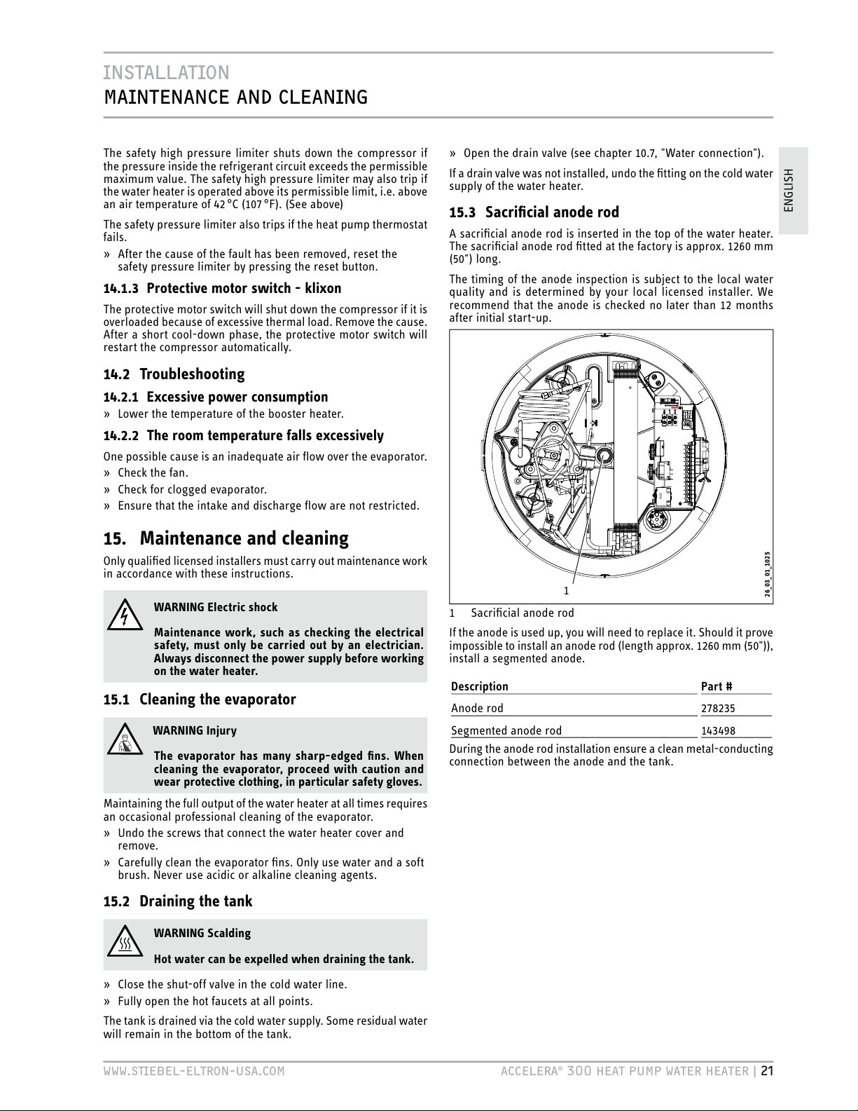
15.3 Sacrificial anode rod
A sacrificial anode rod is inserted in the top of the water heater.
The sacrificial anode rod fitted at the factory is approx. 1260 mm
(50") long.
The timing of the anode inspection is subject to the local water
quality and is determined by your local licensed installer. We
recommend that the anode is checked no later than 12months
after initial start-up.
CAUTION :
Risk of electric shock
Use copper conductors only
26_03_01_1025
1
1 Sacrificial anode rod
If the anode is used up, you will need to replace it. Should it prove
impossible to install an anode rod (length approx. 1260 mm (50")),
install a segmented anode.
Description Part #
Anode rod 278235
Segmented anode rod 143498
During the anode rod installation ensure a clean metal-conducting
connection between the anode and the tank.
Page 22

22 | ACCELERA® 300 HEAT PUMP WATER HEATER WWW.STIEBEL-ELTRON-USA.COM
INSTALLATION
MAINTENANCE
AND CLEANING
15.4 Descaling
» Close the shut-off valve in the cold water supply to the tank.
» Draw water from the tank to relieve the pressure inside the
water heater.
CAUTION :
Risk of electric shock
Use copper conductors only
26_03_01_1025
3
1 Low pressure fill port
2 High pressure fill port
3 Booster heater flange
» Unscrew the booster heater flange and remove element.
» Immerse scaled sections of the heater element into a
descaling liquid (for example citric acid), until the limescale
has dissolved.
» Flush the descaling liquid (white vinegar is another example)
off and allow the immersion heater element to dry.
15.5 Checking valves
15.5.1 Safety valve (on-site provision)
For reasons of safety, it is necessary to check the T&P valve for
proper function from time to time.
» Crack open the safety valve until a full jet of water is
discharged.
» Close the safety valve when the check is complete.
How quickly limescale builds up depends on the local water quality
and the hot water temperature. As your local licensed installers
are familiar with your local water quality, let them determine the
timing of the next service.
15.5.2 Pressure reducing valve (on-site provision)
» Check the on site pressure relief valve for function. If
required, replace the valve.
15.5.3 Checking refrigerant levels
» When checking refrigerant levels at fill ports be sure to use
new crush washers (supplied with unit).
1
2
Page 23
ENGLISH
WWW.STIEBEL-ELTRON-USA.COM ACCELERA® 300 HEAT PUMP WATER HEATER | 23
INSTALLATION
SPECIFICATION
16. Specification
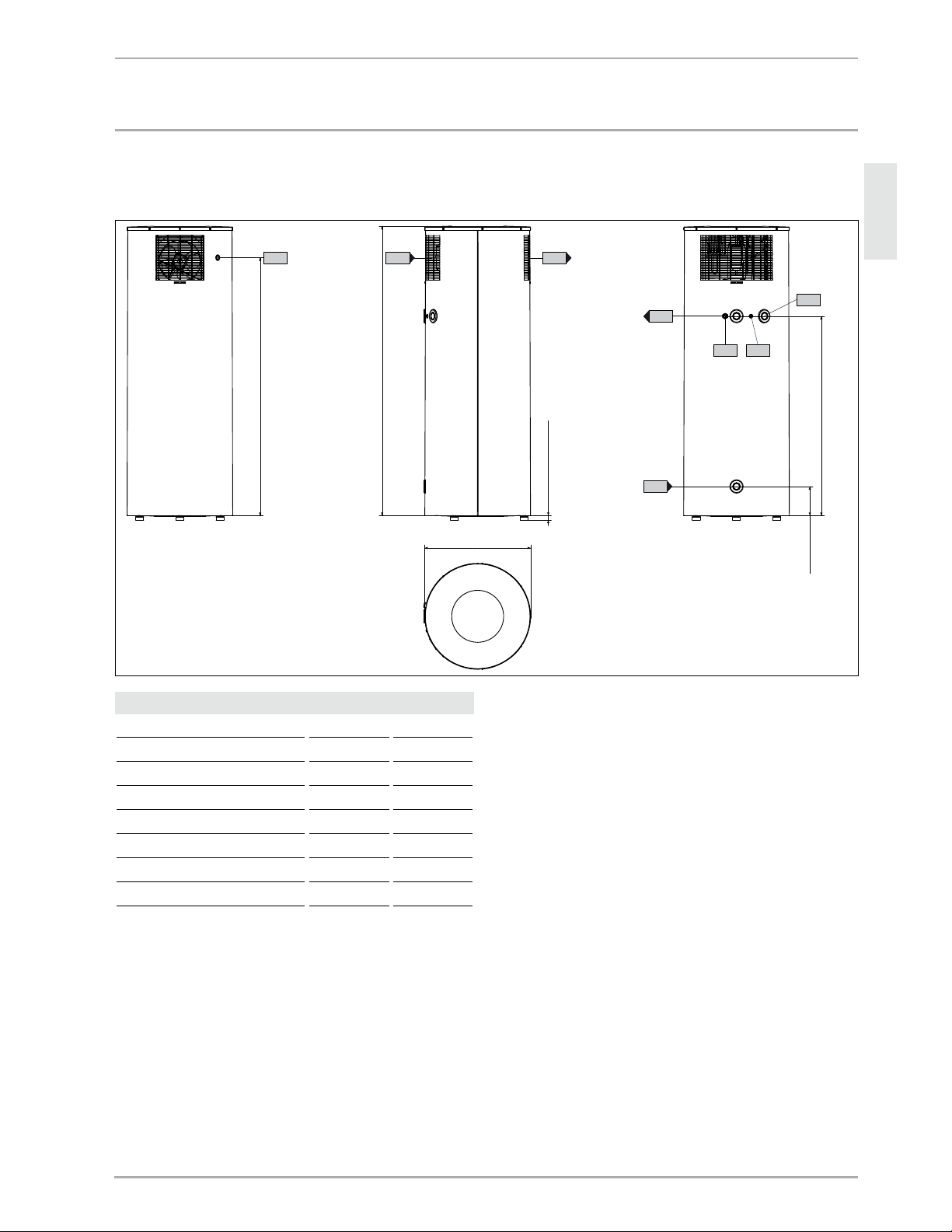
16.1 Connection and dimensions
1840 (72.44")
22-32 (0.87"-1.26")
660 (25.98")
1695 (66.73")
185 (7.28")
1265 (49.8")
b01
g02
g01
c01
c06
c13
d45 d43
D0000018497
Accelera® 300 Connections and dimensions
b01 Entry electrical cables
c01 Cold water inlet Male thread G 1
c06 DHW outlet Male thread G 1
c13 T&P valve Male thread G 3/4
d43 Condensate overflow
d45 Condensate drain Male thread G 3/4
g01 Air intake
g02 Air discharge
Page 24

24 | ACCELERA® 300 HEAT PUMP WATER HEATER WWW.STIEBEL-ELTRON-USA.COM
INSTALLATION
SPECIFICATION
16.2 Wiring diagram
1,65 kW
L1 L2
G
26_03_ 01_0882
E1 Booster heater
F1 High limit safety cut-out, booster heater
F2 Compressor motor protection (Klixon)
F3 Safety pressure limiter (high pressure)
M1 Compressor
M2 Fan
N0 Heat pump control thermostat
N1 Thermostat - booster heater
N2 Frost monitor
X0 Main terminal
X1 Heat pump terminal
X2 Ground, compressor
X3 Ground, booster heater
Z1 Capacitor
Page 25
ENGLISH
WWW.STIEBEL-ELTRON-USA.COM ACCELERA® 300 HEAT PUMP WATER HEATER | 25
INSTALLATION
SPECIFICATION
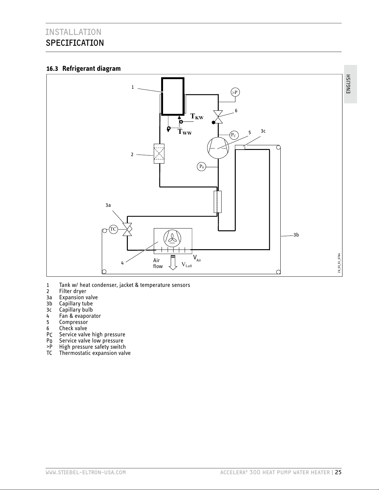
16.3 Refrigerant diagram
P
C
P
TC
V
Luft
T
KW
T
WW
P
0
1
2
3a
3b
4
Air
flow
5
6
26_03_ 01_0764
V
Air
3c
1 Tank w/ heat condenser, jacket & temperature sensors
2 Filter dryer
3a Expansion valve
3b
Capillary tube
3c Capillary bulb
4 Fan & evaporator
5 Compressor
6 Check valve
PC Service valve high pressure
P0 Service valve low pressure
>P
High pressure safety switch
TC
Thermostatic expansion valve
Page 26

26 | ACCELERA® 300 HEAT PUMP WATER HEATER WWW.STIEBEL-ELTRON-USA.COM
INSTALLATION
SPECIFICATION
16.4 Technical Data
Model Heat pump water heater
Type Accelera 300
Part number 222423
Version With passive defrosting and booster heater
Operating details
Lower application limit for heat pump operation
(air temperature)
°C (°F)
6 (42.8)
Upper application limit for heat pump operation
(air temperature)
°C (°F)
42 (107.6)
Hot water temperature, heat pump °C (°F) 60 (140)
Hot water temperature, booster heater °C (°F) 60 (140)
Air flow rate m3/h (CFMs) 550 (324)
Tank capacity l (Gal) 303 (80.044)
Refrigerant R 134a
Refrigerant / filling weight g (oz) 900 (32)
Water heater height (minimum) mm (inch) 1865 (73.43)
Water heater height (maximum) mm (inch) 1903 (74.92)
Water heater diameter mm (inch) 660 (25.98)
Dimension when tilted incl. packaging mm (inch) 2225 (87.60)
Dimension when tilted, excl. top packaging mm (inch) 2150 (84.65)
Dimension when tilted, excl. wooden pallet and top packaging mm (inch) 2030 (79.92)
Dimension when tilted, excl. packaging mm (inch) 1990 (78.35)
Weight (dry tank) kg (lb) 130 (287)
Weight (wet) kg (lb) 432 (950)
Water connection with adaptor Union to 3/4"
Condensate drain 3/4"
Condenser Rollbond safety heat exchanger
Permissible operating pressure, low (cold) side* MPa (Psi) 0.6 (87)
Permissible positive pressure, high (hot) side* MPa (Psi) 2.4 (348.1)
Sound pressure level (spl) dB(A) 55.2
Maximum inlet water temperature °F (°C) 140 (60)
Page 27

ENGLISH
WWW.STIEBEL-ELTRON-USA.COM ACCELERA® 300 HEAT PUMP WATER HEATER | 27
INSTALLATION
SPECIFICATION
Model Heat pump water heater
Electrical details
Power connection, voltage / frequency L1,L2,G / 208-240 V / 60/50 Hz
Protection IP 24
Maximum power consumption (Tamb = 42 °C (108 °F),
Twater = 60 °C (140 °F), 240 V)
kW
2.2
Required circuit breaker size A 15A double pole breaker
Rated power consumption, heat pump A 2.5
Rated power consumption HP (in accordance with
DIN 8947, at 15 °C (59°F) air temperature, 70% relative humidity
and 45 °C (113°F)water temperature)
kW
0.5
Power consumption, booster heater kW 1.690
Heating output HP (at 15 °C (59°F) air temperature, 70% relative
humidity, water heat-up from 15 °C(59°F) to 60 °C (140 °F), in
accordance with EN 255 T3, 240V/60Hz)
kW
approx. 1.7
Coefficient of Performance (COP) (t) (at 15 °C (59 °F) air
temperature, 70% relative humidity, water heat-up from 15 °C (59
°F) to 60 °C (140 °F), in accordance with
EN 255 T3, 240V/60Hz)
3.18
* Standard automotive R-12/R-134A manifold gauge set can be used to test and fill refrigerant.
Page 28

WARRANTY
ENvIRONMENT AND RECYCLING
28 | ACCELERA 300 WWW.STIEBEL-ELTRON-USA.COM
Environment and recycling
Please help us protect the environment. Dispose of the appliance
and its packaging in accordance with national regulations.
KYOTO | R134a
This device is filled with refrigerant R134a.
Refrigerant R134a is a CFC greenhouse gas mentioned in the Kyoto
protocol with a global greenhouse potential (GWP) = 1300.
Never release refrigerant R134a to atmosphere.
WARRANTY
Stiebel Eltron warrants to the original owner that the Accelera® 300 heat pump water heater will be free from defects in
workmanship and materials for a period of ten (10) years from the date of purchase.
Should the part(s) prove to be defective under normal use during this period, Stiebel Eltron, Inc. will be responsible for
replacement of the defective part(s) only. Stiebel Eltron, Inc. will not be liable for any costs of transportation, removal,
reinstallation, or any other labor or freight charges that may arise in connection with a warranty claim or any incidental or
consequential expenses.
This warranty does not apply:
1. To conditions resulting from a failed component or part that is not part of the heat pump
Water heater
2. To freeze damage
3. To conditions resulting from misuse, abuse, neglect, accident, or alteration
4. To conditions resulting from the introduction of harmful chemicals, caustic fluids, or liquids
deleterious to copper tubing, including improperly applied or maintained heat transfer fluids
5. To excessive pressure
6. To conditions resulting from floods, earthquakes, winds, fire, lightning, or circumstances beyond
the manufacturer’s control
7. To installation methods which do not conform to relevant national, state or local codes and
ordinances, good industry practices or applicable manuals, diagrams, technical bulletins or
written installation instructions; and, to applications other than medium temperature.
To obtain service under this warranty, the owner must first secure written authorization from stiebel eltron, inc. The owner shall be
required to show proof of purchase date, and to pay all transportation costs to return the defective part(s) for repair or replacement.
Page 29

ESPAÑOL
WWW.STIEBEL-ELTRON-USA.COM ACCELERA® 300 CALENTADOR DE AGUA CON BOMBA ELÉCTRICA DE CALOR | 27
INFORMACIÓN GENERAL | OPERACIÓN
GUÍA DE ENCENDIDO RAPIDO
Por favor, leer.
Leer estas instrucciones detenidamente y tenerlas
en cuenta en adelante. Si se transfiere el calentador
de agua a un tercero, por favor entregarle estas
instrucciones.
Este manual incluye información importante sobre el manejo
seguro y eficiente del calentador de agua. Mantener el manual
cerca del calentador en todo momento.
Solo un instalador autorizado que haya leído y comprendido estas
instrucciones deberá instalar el calentador. Se deben cumplir
todos los códigos nacionales, estaduales y locales; de lo contrario,
se podrían ocasionar fallas en el equipo, heridas severas, o la
muerte.
Mientras se instala el calentador, se deberá desconectar el
suministro de electricidad.
Las imágenes que se muestran están diseñadas para ayudar
a comprender las instrucciones, y pueden diferir de la versión
del calentador de agua real. No se aceptarán reclamos por
malinterpretar las imágenes.
Responsabilidad limitada:
Todos los detalles y la información de este manual se recopilaron a
partir de la consideración de las normas y regulaciones pertinentes,
el estado del artefacto y nuestros extensos conocimientos y
experiencia.
No seremos responsables de las pérdidas en las que se incurrieren
por:
- El incumplimiento de estas instrucciones
- El uso indebido
- La instalación del calentador realizada por personal no
calificado
- Modificaciones no permitidas
- Modificaciones técnicas
- Uso no autorizado de los repuestos
Copyright:
Estas instrucciones de uso e instalación están sujetas a copyright.
La transferencia de estas instrucciones a terceros, la copia de
cualquier tipo, ya sea parcial o total, el uso de dicha copia y/o la
trasferencia de su contenido, se encuentran prohibidos sin nuestro
permiso por escrito.
Las violaciones son susceptibles de reclamos por compensación.
Se reservan otros reclamos.
Somos titulares del copyright sobre:
STIEBEL ELTRON Inc.
17 West Street | West Hatfield MA 01088
Tel. 413-247-3380 | Fax 413-247-3369
Email info
@stiebel-eltron-usa.com
www.stiebel-eltron-usa.com
En el caso de tener alguna duda sobre la instalación o el uso del
calentador de agua, contáctese con nuestro servicio de atención
al cliente. Tel. (EE.UU.) 800-582-8423 o 413-247-3380.
Accelera® 300 Guía de encendido rápido
A. ASPECTOS GENERALES: Este calentador de agua se
conecta como cualquier otro calentador de agua
eléctrico, salvo algunas excepciones pequeñas.
Cerciorarse de que se cumplan todos los códigos
estaduales y locales durante la instalación. Esta
página no debe interpretarse como un substituto
del manual de instalación. Cerciorarse de que se
cumplan todas las precauciones de seguridad.
B. DESEMBALAJE: NO desembalar la unidad del
calentador de agua hasta no haberla ubicado donde
se va a instalar. Seguir todas las instrucciones del
manual y cerciorarse de tener precaución, ya que la
unidad es demasiado pesada. NO sacudir ni inclinar
la unidad pasando los 45 grados sobre la carretilla
de carga. Ver: 10.6
C. INSTALACIÓN / AGUA:
a. Ubicación: Escoger una ubicación adecuada
según el manual. A continuación, instalar el codo
de drenaje de condensado. Cerciorarse de que los
conductos de ventilación se encuentren paralelos a
la pared y que el ventilador mire hacia la parte con
mayor espacio libre de la pared. Por favor, tener en
cuenta que se recomienda el uso de una bandeja de
drenaje de condensado. Ver: 10.6
b. Se proporciona una entrada de ¾ pulgadas desde
las uniones. Para conectarla, se deben respetar los
códigos estaduales y locales sobre las válvulas de
retención, los depósitos de expansión, las válvulas
de cierre, los calibres, etc. Instalar una válvula de
reducción de presión de 70 psi. Por favor, tener en
cuenta que la presión de agua no puede superar los
0,48 MPa (70 psi). Ver: 10.7
c. Conectar una salida de ¾ pulgadas desde las
uniones a la toma de agua caliente.
d. Instalar la válvula de escape de T&P (brindada).
Tener en cuenta: 0,69 MPa / 99°C (100 psi / 210°F).
D. DRENAJE DE CONDENSADO: El drenaje de condensado
va directamente a un drenaje; de lo contrario, utilizar
una bomba de condensado para drenarlo a un lugar
adecuado. Ver: 10.6.1
E. LLENAR Y DESCARGAR EL TANQUE: Dejar correr agua
para cerciorarse de que el tanque esté lleno antes de
conectar el suministro de electricidad.
F. INSTALACIÓN / ELÉCTRICA: Utilizar un interruptor de
dos polos de 240 voltios / 15 amperios y conectarlo al
calentador de agua L1, L2 y toma de tierra. Ver: 16.2
!
A las 5 horas de haberse encendido, el flujo de aire
expulsado debería encontrarse aproximadamente a
-14,4 °c (6 °f) menos que el del lado de la entrada.
PRECAUCIÓN: existe el riesgo de quemaduras por
agua hirviendo. Existe el riesgo de quemaduras por
agua hirviendo ya que la temperatura del agua que
sale puede ser superior a los 43 c (110°f). Existe el
riesgo de quemaduras por agua hirviendo
Page 30

28 | ACCELERA® 300 CALENTADOR DE AGUA CON BOMBA ELÉCTRICA DE CALOR WWW.STIEBEL-ELTRON-USA.COM
GUÍA DE ENCENDIDO RÁPIDO | OPERACIÓN
HMC
Agua fría
Agua caliente
2
12
15
13
14
11
3
4
5
6
7
8
9
10
1
1 Igualador de presión
2 Conexión del agua caliente (adaptador para la unión de ¾ pulgadas)
3 Válvula mezcladora (provista por el instalador)
4 Conexión para la válvula de T&P de ¾ pulgadas
5 Válvula de T&P de ¾ pulgadas, 0,69 MPa a 99°C (100 psi a 210°F)
(suministrada con la unidad)
6 Válvula de escape de 0,551 MPa (80 psi) (opcional, provista por el instalador)
7 Tanque de expansión (provisto por el instalador)
8 Válvula de cierre directo (provista por el instalador)
9 Válvula de retención (provista por el instalador)
10
Válvula de reducción de presión de 0,48 MPa (70 psi) (provista por el
instalador)
11 Conexión de agua fría (más adaptador para la unión de ¾ pulgadas)
12
Drenaje de condensado (codo incluido con la unidad)
13 Válvula de drenaje (provista por el instalador)
14 Bandeja de drenaje (provista por el instalador)
15
Excedente de condensado
Page 31

ESPAÑOL
WWW.STIEBEL-ELTRON-USA.COM ACCELERA® 300 CALENTADOR DE AGUA CON BOMBA ELÉCTRICA DE CALOR | 29
CONTIENDO | OPERACIÓN
INFORMACIÓN GENERAL __________________________________________ 27
GUÍA DE ENCENDIDO RÁPIDO _____________________________________ 27
FUNCIONAMIENTO ________________________________________________ 30
1. Overview __________________________________________________ 30
2. Aspectos generales _______________________________________ 30
2.1. Información para comprender los símbolos ______________30
3. Seguridad __________________________________________________ 34
3.1. Instrucciones generales de seguridad ______________________34
3.2. Uso correcto _____________________________________________________ 34
3.3. Uso incorrecto ___________________________________________________34
3.4. Calificación del personal ______________________________________34
3.5. Equipo de seguridad ___________________________________________34
3.6. Riesgos específicos _____________________________________________34
4. Descripción del calentador de agua _____________________ 35
4.1. Descripción de las funciones _________________________________ 35
5. Uso _________________________________________________________ 35
5.1. Encendido inicial realizado por un instalador autorizado
_____________________________________________________________________ 35
5.2. Encendido y apagado __________________________________________ 35
5.3. Apagado de emergencia ______________________________________35
6. Cuidado y mantenimiento ________________________________ 35
6.1. Limpieza del depósito de cal _________________________________36
7. Qué hacer si… _____________________________________________ 36
7.1. ...el calentador no calienta el agua _________________________36
7.2 . ...gotea la válvula de seguridad del suministro de agua
fría ________________________________________________________________36
7.3 . ...gotea el drenaje de condensado __________________________36
7.4 . ...el consumo de electricidad es muy elevado ____________36
7.5. ...la temperatura del ambiente desciende de forma
excesiva ___________________________________________________________36
7.6 . ...ocurre otra falla ______________________________________________ 36
8. Seguridad __________________________________________________ 36
8.1. Instrucciones generales de seguridad ______________________ 36
8.2. Uso incorrecto ___________________________________________________ 37
8.3. Calificaciones ____________________________________________________37
8.4. Instrucciones, normas y reglas ______________________________37
8.5. Instalación del agua ____________________________________________ 37
8.6. Instalación eléctrica ____________________________________________ 37
9. Descripción del calentador de agua _____________________ 38
9.1. Entrega común __________________________________________________38
9.2. Accesorios especiales __________________________________________ 38
10. Instalación _________________________________________________ 38
10.1. Ubicación de la instalación ___________________________________38
10.2. Inspección del estado del calentador luego del traslado
marítimo __________________________________________________________ 39
10.3. Manejo ____________________________________________________________39
10.4. Almacenamiento ________________________________________________ 39
10.5. Posicionamiento del calentador _____________________________39
10.6. Desembalaje del calentador __________________________________40
10.7. Conexión del agua ______________________________________________ 42
10.8. Suministro de electricidad: 240V/ interruptor de dos
polos 15 A ________________________________________________________42
11. Encendido inicial __________________________________________ 44
11.1. Encendido inicial ________________________________________________44
11.2. Apagado __________________________________________________________44
11.3. Reinicio ___________________________________________________________44
12. Configuración______________________________________________ 44
12.1. Ajuste de la temperatura del agua __________________________44
13. Entrega del calentador ___________________________________ 44
14. Resolución de problemas ________________________________ 44
14.1. Equipo de seguridad del calentador ________________________44
14.2. Resolución de problemas _____________________________________ 45
15. Mantenimiento y limpieza ________________________________ 45
15.1. Limpieza del evaporador ______________________________________ 45
15.2. Drenaje del tanque _____________________________________________ 45
15.3. Barra de ánodo de sacrificio _________________________________ 45
15.4. Limpieza del depósito de cal _________________________________46
15.5. Revisión de las válvulas _______________________________________46
16. Especificaciones ___________________________________________ 47
16.1. Conexiones y medidas _________________________________________47
16.2. Diagrama del cableado
________________________________________48
16.3. Diagrama de la refrigeración_________________________________49
16.4. Información técnica ____________________________________________50
GARANTÍA _________________________________________________________ 52
MEDIOAMBIENTE Y RECICLAJE ___________________________________ 52
Page 32

OPERACIÓN
FUNCIONAMIENTO
, ASPECTOS GENERALES
30 | ACCELERA® 300 CALENTADOR DE AGUA CON BOMBA ELÉCTRICA DE CALOR WWW.STIEBEL-ELTRON-USA.COM
1. Funcionamiento, aspectos
generales
Parte delantera del calentador de agua
7
6
2
5
4
3
1
26_03_ 01_1338
4
4
8
1 Cubierta del calentador de agua
2 Apertura de la válvula de P&T
3 Drenaje de condensado
4 Patas de nivelación
5 Entrada de agua fría
6 Salida de agua caliente
7 Entrada de aire
8 Excedente de condensado
El calentador de agua extrae el calor del aire del ambiente y utiliza
esta energía para calentar el agua.
El calentador de agua cuenta con un tanque de agua de 80 galones
[300 litros]. El exterior del tanque de agua está aislado con espuma
de poliuretano para evitar la pérdida de calor. El revestimiento
del calentador está hecho de láminas de acero recubiertas con
pintura electrostática.
El tanque de agua, esmaltado en su interior, se apoya sobre tres
patas niveladoras anti-vibración y de altura ajustable.
Parte trasera del calentador de agua
9
10
26_03_ 01_1337
9 Descarga de aire
10 Entrada del cable eléctrico
2. Información general
El capítulo Funcionamiento está destinado para usuarios e
instaladores autorizados.
El capítulo Instalación
está destinado solo para instaladores
autorizados.
2.1 Información para comprender los símbolos
2.1.1 Disposición de la información de seguridad
PELIGRO DE SHOCK ELÉCTRICO
ANTES DE REALIZAR CUALQUIER TRABAJO
SOBRE EL ARTEFACTO, DESCONECTE TODOS LOS
POLOS DE LA RED ELÉCTRICA.
1
3
4
2
1 Símbolo (ver capítulo “Símbolos”)
2 Palabra clave (ver capítulo “Palabras claves”)
3 Designations (see chapter "Symbols")
4 Texto informativo
Page 33

OPERACIÓN
INFORMACIÓN
GENERAL
ESPAÑOL
WWW.STIEBEL-ELTRON-USA.COM ACCELERA® 300 CALENTADOR DE AGUA CON BOMBA ELÉCTRICA DE CALOR | 31
2.1.2 Símbolos
Símbolo Descripción
Lesiones
Electrocución
Quemaduras por agua hirviendo o por otros
factores
!
Otras situaciones
Fuego
Explosión
Eliminación del calentador de agua
2.1.3 Palabras claves
PALABRA CLAvE
PELIGRO
La palabra clave PELIGRO indica la información
que se debe obedecer; de lo contrario se
ocasionarán lesiones graves o la muerte.
ADVERTENCIA
La palabra clave ADVERTENCIA indica la
información que se debe obedecer; de lo
contrario se podrán ocasionar lesiones graves o
la muerte.
PRECAUCIÓN
La palabra clave PRECAUCIÓN indica la
información que se debe obedecer; de lo
contrario se podrán ocasionar lesiones
relativamente graves o leves.
2.1.4 Símbolos presentes en este documento
Lea el texto seguido a este símbolo con detenimiento.
» Los textos en los que se encuentra el símbolo "»" indican que
se debe realizar una acción, la cual se describe paso a paso.
- Los textos en los que se encuentra el símbolo "–" indican
listas.
2.1.5 Unidades de medida presentes en este
documento
En este documento, las medidas se encuentran en
milímetros (pulgadas).
2.1.6 Información del paquete
Etiqueta informativa “Peso excesivo”
! !
Hoher Schwerpunkt
High balance point
Hoog zwaartepunt
Centre de gravité en partie haute
Hög tyngdpunkt
Alto centro di graviá
Alto centro de gravedad
Achtung - Attention - Attentie - Attention
Uppmärksamhet - Oppmerksomhet
Attenzione - Atención
264623-33631
Etiqueta informativa “Trasladar en posición vertical”
!CHTUNG!TTENTION
4RANSP ORTUN D!UFS TELLUN G
$AMITDAS'ERËTVOR"ESCHËDIGUNGENGESCHàTZTISTSOLLTEESBISANDEN-ONTAGEORTINDER6ERPACKUNGTRANSPORTIERTWERDEN
'ERËTSENKRECHTTRANSPORTIEREN"EI
BEENGTEN4RANSPORTBEDINGUNGENKANNDAS'ERËTAUCHKURZZEITIGGENEIGTWERDEN"EACHTEN3IEDIEWEITEREN(INWEISEZUM!UFSTELLENUND!USRICHTENDES'ERË
TESINDERBEILIEGENDEN'EBRAUCHSUN D-ONTAGEANWEISUNGUM3CHËDENAM'ERËTZUVER MEIDEN
4RANSP ORTAN DINS TALLAT ION
4OPR OTEC TTH EEQ UIPM ENT AGAI NST DAMAG EIT MUS TBE TRA NSPO RTED INS IDE ITS DEDIC ATED PAC KAGI NGU NTIL THE INS TALL ATIO NFA CILI TYI SAR RIVED
4RANSP ORTTH EEQU IPMENT
UPRIGHT
7HERESPACEISRESTRICTEDYOUMAYALSOMOVEBRIEFLYTHEEQUIPMENTTIPPEDBACKWARDSATANANGLE/BSERVETHENOTESONINSTALLATIONANDFITTINGOFTHE
EQUIPMENTWHICHCANBEFOUNDINTHEENCLOSEDINSTALLATIONANDOPERATINGINSTRUCTIONSTOAVOIDPOSSIBLEDAMAGETOTHEEQUIPMENT
'ERËTNURSENKRECHTODERGGFGENEIGTTRANSPORTIEREN
-OVETHISMACHINEONLYINAVERTICALPOSITIONORIFREQUIREDSLIGHTLYINCLINEDWITHTHECONTROLFACIAPOINTUP
280306-34594
Page 34

OPERACIÓN
INFORMACIÓN
GENERAL
32 | ACCELERA® 300 CALENTADOR DE AGUA CON BOMBA ELÉCTRICA DE CALOR WWW.STIEBEL-ELTRON-USA.COM
2.1.7 Información que figura en el calentador de
agua
For reason
of
corrosion
protection
use flat
gasket ring
28030 5 - 35826
BURN
HOT
CAUTION
DANGER
!
284760-34684
WW Austritt
DHW outlet
2
803
0
4
-34
6845
Warning
A temperature and pressure relief valve
must be fitted to the clearly marked
socket. The valve drain outlet pipe
must not be sealed or blocked, and the
valve easy gear is to be operated
at least once every six month.
28
0
5
58-
34684
Drain
28
0
3
0
2-3481284594
KW Eintritt
CW Inlet
2
80303
-
3
46845
For reason
of
corrosion
protection
use flat
gasket ring
28030 5 - 35826
Drain
28
0
3
0
2-3481284594
Relief valve
Plumber:
The relief valve installation
must be fitted to this socket.
280557-35826
2
4
6
1
7
3
5
26_03_ 01_1355
3
1
1 Etiqueta informativa “Drenaje de condensado”
2 Etiqueta informativa “Riesgo de quemadura por agua
hirviendo”
3 Etiqueta informativa “Conexión”
4 Etiqueta informativa “Salida de agua caliente”
5 Etiqueta informativa “Válvula de escape”
6 Etiqueta informativa “Ubicación de la válvula de escape
durante su instalación”
7 Etiqueta informativa “Entrada de agua fría”
Power supply
Disconnect power supply
before opening the cover.
2
80
5
56-3
4
68425
Type: Accelera 300/WHP 300
Heat pump:
PN (Air 42° / Water 60°):
IN (Air 42° / Water 60°):
Type of Refrigerant:
Refrigerant charge:
Max. operating pressure:
Lock rotor current:
MCA:
Rated load compressor:
Motor fan:
Order-No.: 222423
DHW-cylinder:
Additional heating element:
Max. operating pressure:
Max. operating temperature:
Type of cylinder material:
Cylinder capacity:
Test pressure storage tank:
Observe the installation manual! Tested for leaks!
Made in Germany
No.: 8443 / 005204
Voltage / Frequency:
Breaker:
P (rated power input):
Maximum allowable ratings
Protection class:
Nmax
Single phase 220-240 V, 50/60 Hz
15 amp.
2200 W, 9.17 A
IP 24
*222423844300520415*
1690 W
87 psi /600
kPa
168.8 °F /76 °C
Glass lined steel
80.044 Gal /303 l
130.5 psi / 900 kPa
0.5 kW
2.17 A
R134A
1.9842 Lb. /900 g
348.1 psi /2.4 MPa
13.4 A
10.4 A
2.3 A
38 W
STIEBEL ELTRON INC
17 West Street
West Hatfield, MA 01088
USA
282209-35237
DE: Enthält vom Kyoto - Protokoll erfasste fluorierte Treibhausgase - hermetisch geschlossenes System.
GB: Contains fluorinated greenhouse gases covered by the Kyoto Protocol - hermetically sealed.
FR: Comprend les gaz à effet de serre fluorés enregistrés par le protocole de Kyoto - systèmes hermétiquement scellés.
NL: Bevat gefluoreerde broeikasgassen die onder het Kyoto-protocol vallen - hermetisch gesloten systeem.
SE: Innehåller av Kyoto - protokollet registrerade flourerande växthusgaser i hermetiskt förslutna system.
PL: Zawiera fluorowane gazy cieplarniane ujęte w Protokole z Kioto - hermetycznie zamknięty układ.
CZ: Obsahuje fluorizované skleníkové plyny, obsažené v Kjótském protokolu - hermeticky uzavřený systém.
ES: Sistema herméticamente cerrado que contiene gases de efecto invernadero mencionados en el protocolo de Kioto.
DK: Indeholder fra Kyoto-protokollen registrerede, fluorerede drivhusgasser – hermetisk lukket system.
NO: Inneholder fluorerte drivhusgasser som omfattes av Kyotoprotokollen - hermetisk lukket system.
FI: Sisältää Kioton sopimuksen alaisia fluorattuja kasvihuonekaasuja - ilmatiiviisti suljettu järjestelmä.
284436-34741
BG: Съдържа посочените в Протокола от Киото флуорирани парникови газове - херметически затворена система.
HU: A Kiotói Jegyzıkönyv szerinti fluortartalmú üvegházhatású gázokat tartalmaz - hermetikusan zárt rendszer.
IT: Contiene gas fluorurati ad effetto serra disciplinati dal protocollo di Kyoto - Impianto ermeticamente chius.
RO: Conține un sistem închis ermetic contra emisiei de gaze fluorine monitorizat de protocolul Kyoto.
8
11
26_03_ 01_1356
10
9
8 Etiqueta informativa “Conexión eléctrica”
9 Tipo de placa
10
Etiqueta informativa “Gases Fluorados”
11 Etiqueta informativa “Consumo de electricidad eficiente”
1 Etiqueta informativa “Drenaje de condensado”
Esta etiqueta muestra dónde se encuentra el drenaje del
calentador.
Drain
280302-3481284594
280302-34812.
2 Etiqueta informativa “Riesgo de quemaduras por agua
hirviendo”
BURN
HOT
CAUTION
DANGER
!
284760-34684
284760-34684.
3 Etiqueta informativa “Conexión”
For reason
of
corrosion
protection
use flat
gasket ring
28030 5 - 35826
280305-35826
Page 35

OPERACIÓN
INFORMACIÓN
GENERAL
ESPAÑOL
WWW.STIEBEL-ELTRON-USA.COM ACCELERA® 300 CALENTADOR DE AGUA CON BOMBA ELÉCTRICA DE CALOR | 33
4 Etiqueta informativa “Salida de agua caliente”
WW Austritt
D
HW outlet
280304-346845
280304-34684
5 Etiqueta informativa “Válvula de escape”
Warning
A
temperature and pressure relief valve
m
ust be fitted to the clearly marked
s
ocket. The valve drain outlet pipe
m
ust not be sealed or blocked, and the
v
alve easy gear is to be operated
a
t least once every six month.
280558-34684
280558-34684
6
Etiqueta informativa “Ubicación de la válvula de escape
durante su instalación”
R
elief valve
P
lumber:
T
he relief valve installation
m
ust be fitted to this socket.
280557-35826
280557-35826
7 Etiqueta informativa “Entrada de agua fría”
K
W Eintritt
C
W Inlet
280303-346845
280303-34684
8 Etiqueta informativa “Conexión eléctrica”
Power supply
D
isconnect power supply
b
efore opening the cover.
280556-3468425
280556-34684
9 Tipo de placa
Type: Accelera 300/WHP 300
Heat pump:
PN (Air 42° / Water 60°):
IN (Air 42° / Water 60°):
Type of Refrigerant:
Refrigerant charge:
Max. operating pressure:
Lock rotor current:
MCA:
Rated load compressor:
Motor fan:
Order-No.:
222423
DHW-cylinder:
Additional heating element:
Max. operating pressure:
Max. operating temperature:
Type of cylinder material:
Cylinder capacity:
Test pressure storage tank:
Observe the installation manual! Tested for leaks!
Made in Germany
No.: xxxx / xxxxxx
Voltage / Frequency:
Breaker:
P (rated power input):
Limits for heat pump operation
:
Maximum allowable ratings
Protection class:
Nmax
Single phase 220-240 V, 50/60 Hz
15 amp.
6 °C / +42 °C
2200 W, 9.17 A
IP 24
*222423xxxxxxxxxxxx*
1690 W
87 psi /
600 kPa
168.8 °F /
76
°C
Glass lined steel
80.044 Gal /303 l
130.5 psi / 900 kPa
0.5
kW
2.17
A
R134a
1.9842 Lb. /900 g
348.1 psi /2.4
MPa
13.4 A
10.4 A
2.3 A
38 W
STIEBEL ELTRON INC
17 West Street
West Hatfield, MA 01088
USA
282209
-35793
26_03_ 01_1357
10 Etiqueta informativa “Gases Fluorados”
DE: Enthält vom Kyoto - Protokoll erfasste fluorierte Treibhausgase - herm etisch geschlossenes System.
GB: Contains fluorinated greenhouse gases covered by the Kyoto Protocol - herm etically sealed.
FR: Comprend les gaz à effet de serre fluorés enregistrés par le pro tocole de Kyoto - systèmes hermétiquement scellés.
NL: Bevat gefluoreerde broeikasgassen die onder het Kyoto-protocol vallen - hermetisch gesloten systeem.
SE: Innehåller av Kyoto - protokollet registrerade flourerande växthusgase r i hermetiskt förslutna system.
PL: Zawiera fluorowane gazy cieplarniane ujęte w Protokole z Kioto - hermetycznie zamknięty układ.
CZ: Obsahuje fluorizované skleníkové plyny, obsažené v Kjótském protokolu - her meticky uzavřený systém.
ES: Sistema herméticamente cerrado que contiene gases de efecto invernadero mencionados en el protocolo de Kioto.
DK: Indeholder fra Kyoto-protokollen registrerede, fluorerede drivhusgasser – hermetisk lukket system.
NO: Inneholder fluorerte drivhusgasser som omfattes av Kyotoprot okollen - hermetisk lukket system.
FI: Sisältää Kioton sopimuksen alaisia fluorattuja kasvihuonekaasuja - ilmatiiviisti suljettu järjeste lmä.
284436-34741
BG: Съдържа посочените в Протокола от Киото флуорирани парникови газове - херметически затворена система.
HU: A Kiotói Jegyzıkönyv szerinti fluortartalmú üvegházhatású gázokat tartalmaz - hermetikusan zárt rendszer.
IT: Contiene gas fluorurati ad effetto serra disciplinati dal protocollo di Kyoto - Impianto ermeticamente chius.
RO: Conține un sistem închis ermetic contra emisiei de gaze fluorine monitorizat de protocolul Kyoto.
26_03_ 01_1386
11 Etiqueta informativa “Consumo de electricidad eficiente”
282980-36142
Mantener legibles todas las etiquetas informativas.
La ilegibilidad de la información y los símbolos de
seguridad podrían ocasionar situaciones peligrosas.
Page 36

OPERACIÓN
SEGURIDAD
34 | ACCELERA® 300 CALENTADOR DE AGUA CON BOMBA ELÉCTRICA DE CALOR WWW.STIEBEL-ELTRON-USA.COM
3. Seguridad
Este capítulo da un vistazo general de todas las medidas
importantes que hay que tomar para el uso seguro y sin
inconvenientes del calentador.
3.1 Instrucciones generales de seguridad
Utilizar el calentador de agua una vez que se encuentre
completamente instalado y cuente con todo el equipo de seguridad
debidamente colocado.
El uso inadecuado de herramientas o el manejo incorrecto puede
producirle daños al calentador.
PELIGRO Quemaduras por agua hirviendo
El agua se calienta dentro del tanque de agua
hasta alcanzar los 60°C (140°F). Existe el riesgo de
quemaduras por agua hirviendo, ya que la temperatura
del agua que sale puede ser superior a los 43 C (109°F).
» Cerciorarse de que la salida del agua no alcance el
cuerpo.
PRECAUCIÓN Lesiones
Si menores o personas con capacidades físicas,
sensoriales o mentales limitadas tienen permitido
controlar el calentador, cerciorarse de que solo lo
hagan bajo supervisión o luego de que una persona
responsable de su seguridad los haya instruido de
forma adecuada.
» Se debe supervisar a los menores para cerciorarse
de que no jueguen con el calentador.
No apoyar objetos sobre el calentador.
Los objetos apoyados sobre el calentador pueden
aumentar el nivel de ruido que producen las
vibraciones del calentador.
No cubra el calentador.
El calentador extrae aire del ambiente, al cubrir las
ranuras por las que entra, se reduce su cantidad. De
esta manera, se disminuye la eficacia del calentador y
puede ocurrir que uno de los dispositivos de seguridad
interrumpa el funcionamiento del calentador.
3.2 Uso correcto
El calentador calienta el agua automáticamente.
Se lo puede instalar y utilizar en espacios exteriores o interiores.
La temperatura del aire que extrae no debe ser inferior a los 6°C
(43°F).
Cualquier otro uso que se le dé que difiera del estipulado, se
considerará inadecuado. El cumplimiento de estas instrucciones
también forma parte del uso correcto del calentador.
Cualquier alteración o modificación que se realice al calentador
tornará nulos todos los derechos de la garantía.
3.3 Uso incorrecto
- Los siguientes usos no están permitidos:
- No calentar otro líquido que no sea agua potable.
- No permitir que un personal no calificado (ni autorizado)
instale el calentador.
- No utilizarlo en un ambiente donde extraiga aire graso.
No se debe utilizar el calentador en ambie n te s c on t e mpe r at u ras s u per iore s a
los 42°C (107°F) o infer iores a 6°C (43°F).
Si el calentador extrae aire del exterior, cerciorarse
de que se encuentre apartado del suministro de electricidad cuando la temperatura del aire sea inferior
a los 6°C (43°F).
3.4 Calificación del personal
PELIGRO Lesiones
El manejo indebido del calentador puede ocasionar
lesiones graves y daños al material. El personal
no calificado no puede evaluar la posibilidad de
riesgo. Cerciorarse de que los técnicos calificados
especificados en los capítulos pertinentes lleven a
cabo la instalación, el encendido, el mantenimiento
y las reparaciones.
En el resto del manual, se llamará a estos técnicos “instaladores
autorizados”.
3.5 Equipo de seguridad
Utilizar calzado de seguridad durante el traslado y la ubicación del
calentador de agua. En seco, este calentador de agua pesa 130 kg
(290 lb). El calzado de seguridad reduce el riesgo de lesiones.
3.6 Riesgos específicos
3.6.1 Corriente eléctrica
ADVERTENCIA Descargas eléctricas
El contacto con partes que conducen electricidad pone
en riesgo la vida. Dañar el aislante térmico o las piezas
individuales puede poner en riesgo la vida.
» Si se detectan daños en el aislante, cortar el
suministro de electricidad inmediatamente y
solicitar la reparación de esta.
» Cerciorarse de que todo el trabajo relacionado con
la electricidad sea llevado a cabo por un electricista
calificado.
3.6.2 Superficies calientes
PRECAUCIÓN Quemaduras
El contacto con las piezas calientes puede causar
quemaduras.
» Si se trabaja cerca de las piezas calientes, utilizar
prendas y guantes de protección.
» Las tuberías conectadas a la salida de agua caliente
del calentador pueden alcanzar temperaturas
superiores a los 60°C (140°F).
3.6.3 Refrigerante
En la fábrica se rellena el calentador con refrigerante R134A.
ADVERTENCIA Quemaduras por congelación
En el caso de que el calentador pierda refrigerante,
evitar el contacto o la inhalación de los vapores
emanados. Ventilar el ambiente de forma inmediata.
Page 37

OPERACIÓN
DESCRIPCIÓN DEL CALENTADOR DE AGUA
ESPAÑOL
WWW.STIEBEL-ELTRON-USA.COM ACCELERA® 300 CALENTADOR DE AGUA CON BOMBA ELÉCTRICA DE CALOR | 35
Cuando el calentador funciona en condiciones normales, el
refrigerante está contenido dentro de un circuito sellado.
4. Descripción del calentador de agua
El calentador genera agua caliente de forma automática. Cuenta
con una capacidad aproximada de 303 litros (80 galones). La
temperatura del agua caliente está predeterminada de fábrica
para alcanzar los 60°C (140°F).
Al abrir la llave del agua caliente, esta sale del calentador
empujada por el flujo entrante de agua fría.
El calentador funciona como un aire acondicionado, pero no
precisa que se ventile. Utiliza el calor del ambiente para calentar
el agua. El consumo de electricidad y el tiempo que lleva calentar
el agua dependen de la temperatura del ambiente y la humedad.
Al instalar el calentador en un lugar cerrado, la temperatura de
dicho sector disminuirá durante dicha actividad de 1 a 3°C (de 2
a 6°F).
Asimismo, el calentador extrae la humedad del aire y genera
condensado, el cual debe drenarse. Por este motivo, se incorpora
un drenaje de condensado al calentador de agua. Allí se puede
conectar una manguera al drenaje.
Para proteger el tanque de acero de la corrosión, el interior está
revestido con un esmalte especial y está equipado con un ánodo
de sacrificio reemplazable.
Funcionamiento de la bomba eléctrica de calor:
Un circuito sellado en el interior del calentador contiene el
refrigerante R134A (ver “Especificaciones/tabla de datos”). Este
refrigerante no daña la capa de ozono, no es inflamable y se
evapora a temperaturas bajas.
El refrigerante cambia de su estado líquido a gaseoso en el
evaporador, donde se extrae el calor del ambiente. El compresor
absorbe el gas e incrementa su presión. A medida que aumenta
la presión, sube la temperatura del refrigerante. De esta manera,
se calienta el tanque de agua.
Este proceso requiere energía eléctrica. La electricidad (la
potencia del motor) no se pierde, se combina con el condensador
y el refrigerante comprimido. En esta instancia, el gas transfiere
su calor al tanque de agua. Entonces, la válvula de expansión
reduce la presión y el proceso comienza de nuevo.
4.1 Descripción de las funciones
4.1.1 Funcionamiento de la bomba eléctrica de calor
La bomba eléctrica de calor, ubicada en la parte superior del
calentador, extrae la energía térmica del ambiente.
Si se interrumpe el suministro de electricidad durante
el funcionamiento, el compresor se reiniciará una vez
que se equilibre la presión dentro del circuito de refrigeración.
Esta se equilibrará luego de 15 minutos.
4.1.2 Calentador de refuerzo
Ante todo, la bomba eléctrica de calor es la que calienta el agua
del tanque.
En caso de que haya una mayor demanda de agua caliente, o de
que se haya apagado el calentador, y se necesitara agua caliente a
la brevedad, se encenderá por completo el calentador de refuerzo.
Con el fin de ahorrar electricidad, el calentador de refuerzo
calienta los tres cuartos superiores del tanque (aproximadamente
102 litros (27 galones)).
El termostato enciende el calentador de refuerzo cuando la
temperatura del tanque es inferior a los 45°C (112°F). Asimismo, el
termostato apaga el calentador de refuerzo cuando la temperatura
del tanque es superior a los 60°C (140°F).
4.1.3 Descongelación
Cuando el calentador de agua se utilice mínimamente, la
temperatura se mantendrá en los 6°C (42°F). Si esto sucede, es
posible que el evaporador se cubra de escarcha. Esto depende de
la temperatura del aire y el nivel de humedad, en particular si la
temperatura del agua caliente es baja.
El compresor se apaga inmediatamente si la temperatura del
evaporador se mantiene por debajo de los -7°C (20°F) durante un
tiempo considerable. Si la temperatura de la aleta del evaporador
sube por encima de los 3°C (38°F), el compresor se enciende
de nuevo y continúa calentándose el agua. El ventilador sigue
funcionando durante la descongelación.
5. Uso
No es posible regular la temperatura del agua, ya que el calentador
no cuenta con controles. La temperatura del agua caliente está
predeterminada de fábrica para alcanzar los 60°C (140°F).
Si se deseara utilizar una configuración diferente, contactar a un
instalador autorizado de la zona.
ADVERTENCIA Quemaduras por agua hirviendo
El agua se calienta dentro del tanque hasta alcanzar
los 60°C (140°F). Existe el riesgo de quemaduras por
agua hirviendo ya que la temperatura del agua que
sale puede ser superior a los 42 C (108°F). Cerciorarse
de que la salida del agua no alcance el cuerpo.
5.1 Encendido inicial realizado por un
instalador autorizado
El encendido inicial debe ser llevado a cabo por un instalador
autorizado.
5.2 Encendido y apagado
El calentador no cuenta con un botón de ENCENDIDO/APAGADO.
Si al instalar el calentador se utilizó un enchufe para el suministro
de electricidad, se puede desenchufarlo. De lo contrario, se puede
activar el disyuntor para apagarlo.
5.3 Apagado de emergencia
En caso de emergencia, se deben seguir los siguientes pasos:
» Interrumpir el suministro de energía activando el disyuntor o
desenchufando el calentador.
» Cerrar la entrada de agua fría.
6. Cuidado y mantenimiento
El exterior del calentador se puede limpiar con un trapo húmedo.
No se deben utilizar productos de limpieza abrasivos o corrosivos.
No se debe limpiar con una manguera.
» Todos los meses revisar que el drenaje de condensado esté
limpio.
» Todos los meses realizar una inspección visual de la bandeja
de drenaje de condensado (ver en el extremo superior del
calentador el siguiente diagrama). Mirar por la rejilla de
entrada de aire en la parte delantera del calentador. De ser
necesario, se deberá informar al instalador autorizado de la
zona para que retire cualquier obstrucción presente.
Page 38

OPERACIÓN
QUÉ
HACER SI…
36 | ACCELERA® 300 CALENTADOR DE AGUA CON BOMBA ELÉCTRICA DE CALOR WWW.STIEBEL-ELTRON-USA.COM
1
26_03_ 01_1404
1 Bandeja de drenaje de condensado
6.1 Limpieza del depósito de cal
El agua a altas temperaturas filtra la cal. Luego, esta se deposita
en el interior del tanque. Al acumularse los depósitos de cal, la
cantidad de agua caliente del tanque disminuye.
» Por ese motivo, se debe solicitar a un instalador autorizado
que retire el depósito de cal de tanto en tanto. De esta forma,
se prolonga la vida útil del calentador de refuerzo.
» El depósito de cal no se acumula sobre la bomba eléctrica de
calor.
El instalador autorizado, que conoce la calidad del agua de la zona,
indicará cuándo será la próxima inspección de mantenimiento.
» A su vez, solicitar al instalador que revise el ánodo de
sacrificio a menudo.
7. Qué hacer si…
7.1 …el calentador no calienta el agua
» Revisar el suministro de electricidad.
» Revisar la caja de fusibles para ver si se activó un disyuntor.
» Asegurar que haya un disyuntor de dos polos 15 A.
Si el disyuntor se activó, se debe reiniciar o cambiar. Informar al
instalador autorizado si el disyuntor se vuelve a activar.
» Cerciorarse de que la entrada y salida de aire no estén
obstruidas.
El compresor puede estar sobrecargado, ya sea porque la
temperatura del ambiente o del aire extraído es demasiado
alta (>42°C (108°F)) o porque hay una falla en el circuito de
refrigeración. Asimismo, el interruptor de “reinicio automático”
para la protección térmica o el de “reinicio manual” por corte
de seguridad por el exceso del límite de la temperatura pueden
apagar el compresor.
El limitador del nivel de presión alto solo debe ser
reiniciado por el instalador autorizado una vez que se
haya solucionado la falla pertinente.
Tras un lapso corto de enfriamiento, el interruptor de “reinicio
automático” para la protección térmica reiniciará automáticamente
el compresor.
Notificar al instalador autorizado si el calentador de agua no se
reinicia automáticamente.
7.2 ...gotea la válvula de seguridad del
suministro de agua fría
Esta unidad puede funcionar con hasta 0,48 MPa (70 psi) de presión
entrante. La expansión durante el calentamiento provoca que gotee
el agua de la válvula de seguridad. Esto es completamente normal.
Informar al instalador autorizado si el agua sigue goteando una
vez finalizado el calentamiento.
7.3 ...gotea el drenaje de condensado
Esto es bastante frecuente y siempre ocurre cuando la temperatura
superficial del evaporador es inferior a la temperatura del punto
de condensación del ambiente.
7.4 ...el consumo de electricidad es muy
elevado
Por favor, consultar con el instalador calificado y autorizado.
7.5 ...la temperatura del ambiente desciende
de forma excesiva
El funcionamiento del calentador reduce la temperatura del
ambiente de 1 a 3°C (de 2 a 6°F). Informar al instalador autorizado
si la temperatura del ambiente baja de manera inusual.
7.6 ...ocurre otra falla
Informar al instalador autorizado de la zona. Consultar por el
número del calentador en el tipo de placa junto al código de
barras.
Type: Accelera 300/WHP 300
Heat pump:
PN (Air 42° / Water 60°):
IN (Air 42° / Water 60°):
Type of Refrigerant:
Refrigerant charge:
Max. operating pressure:
Lock rotor current:
MCA:
Rated load compressor:
Motor fan:
Order-No.:
222423
DHW-cylinder:
Additional heating element:
Max. operating pressure:
Max. operating temperature:
Type of cylinder material:
Cylinder capacity:
Test pressure storage tank:
Observe the installation manual! Tested for leaks!
Made in Germany
No.: xxxx / xxxxxx
Voltage / Frequency:
Breaker:
P (rated power input):
Limits for heat pump operation
:
Maximum allowable ratings
Protection class:
Nmax
Single phase 220-240 V, 50/60 Hz
15 amp.
6 °C / +42 °C
2200 W, 9.17 A
IP 24
*222423xxxxxxxxxxxx*
1690 W
87 psi /
600 kPa
168.8 °F /
76
°C
Glass lined steel
80.044 Gal /303 l
130.5 psi / 900 kPa
0.5
kW
2.17
A
R134a
1.9842 Lb. /900 g
348.1 psi /2.4
MPa
13.4 A
10.4 A
2.3 A
38 W
STIEBEL ELTRON INC
17 West Street
West Hatfield, MA 01088
USA
282209
-35793
26_03_ 01_1357
1
1 Número del calentador de agua
8. Seguridad
Solo los instaladores calificados y autorizados deberían realizar la
instalación, el encendido inicial, el mantenimiento y la reparación
del calentador de agua.
8.1 Instrucciones generales de seguridad
Utilizar únicamente accesorios o repuestos originales para este
calentador.
PELIGRO Descargas eléctricas
Antes de instalar el calentador, desconectar el
suministro de electricidad.
Page 39

OPERACIÓN
SEGURIDAD
ESPAÑOL
WWW.STIEBEL-ELTRON-USA.COM ACCELERA® 300 CALENTADOR DE AGUA CON BOMBA ELÉCTRICA DE CALOR | 37
ADVERTENCIA Lesiones
Si se dañan las tuberías dentro del calentador, la fuga
de gas refrigerante puede ocasionar quemaduras
físicas por el frío.
No inhalar el refrigerante. Ventilar el ambiente de
manera cuidadosa de inmediato.
» Usar anteojos y guantes protectores durante la
instalación del calentador.
ADVERTENCIA Lesiones
Las piezas en movimiento pueden causar lesiones.
» Cerciorarse de que el ventilador haya dejado de
moverse antes de abrir el calentador.
8.2 Uso incorrecto
Los siguientes usos no están permitidos:
- No instalar el calentador sobre pisos que no están
construidos para soportar peso
- No instalar el calentador en lugares donde haya posibilidad
de escarcha
- No instalar el calentador en ambientes donde corra riesgo de
explotar por polvos, gases o vapores
- No hacer caso omiso de los permisos y las zonas de
seguridad
- No instalar la conexión eléctrica de forma incorrecta
- No utilizar el calentador con el tanque vacío
- No utilizar el calentador con la cubierta destapada
- No utilizar el calentador con otro líquido que no sea agua
potable
- No utilizar otro refrigerante Freón, solo el R134A
8.3 Calificaciones
ADVERTENCIA Lesiones
El manejo indebido puede ocasionar lesiones graves y
daños materiales. El personal no calificado no puede
evaluar el peligro inminente.
Solamente el personal mencionado en las secciones
pertinentes del manual debe realizar las tareas
técnicas.
En el manual, se llamará a estos técnicos “instaladores
autorizados”.
Los instaladores autorizados son responsables de respetar todas
las normas vigentes y relevantes durante la instalación y el
encendido inicial.
8.3.1 Instaladores autorizados
Los instaladores autorizados están capacitados en su área. Trabajan
de acuerdo con su capacitación, conocimiento y experiencia, así
como con su conocimiento de las normas y reglas relevantes. Están
capacitados para reconocer y prevenir los problemas posibles.
8.3.2 Electricista (autorizado)
El electricista es un instalador autorizado que obedece los
requisitos antes mencionados para las instalaciones eléctricas.
8.3.3 Plomero (autorizado)
El plomero es un instalador autorizado que obedece los requisitos
antes mencionados para las instalaciones relacionadas al
suministro de agua.
8.3.4 Servicio de atención al cliente
Para consultas sobre el servicio, por favor contactarse con Stiebel
Eltron, línea directa 1-800-582-8423, interno 25 ó 33.
8.4 Instrucciones, normas y reglas
Obedecer todos los códigos nacionales, estaduales y
locales.
Obedecer las reglas de las empresas de servicios públicos de
electricidad y agua de la zona.
Se tomaron en cuenta las siguientes normas:
UL 499, UL 1995, UL 94-5 VA, UL 174
IEC 60335-1-2-40, IEC 61000-3-2; 1995
IEC 61000-3-3, IEC 55014-1 IEC 55014-2
EMC Directiva 89/336/EEC
EN 255 T3
Leer el tipo de placa del calentador y el capítulo “Especificaciones”.
8.5 Instalación del agua
Se pueden utilizar los siguientes materiales:
- Para la red de agua fría: se pueden utilizar tuberías de acero,
cobre o plástico.
- Para la red de agua caliente: se pueden utilizar tuberías de
cobre o plástico.
» Cerciorarse de que no se contamine el calentador por medio
de las tuberías.
8.6 Instalación eléctrica
Proteger el calentador eléctricamente con un disyuntor de dos
polos 15 A.
Si el calentador se encuentra constantemente conectado al
suministro de electricidad, se debe establecer una manera de
separarlo de la red eléctrica. Esto se realiza mediante un aislante
adicional que desconecta todos los polos que se encuentren, al
menos, a 3 mm (0,12 pulgadas) de separación. Para llevar esto a
cabo, se pueden instalar disyuntores, fusibles, etc. en ese lugar.
En el caso de haber una falla, el equipo de seguridad interrumpe
el circuito eléctrico pertinente.
Page 40

38 | ACCELERA® 300 CALENTADOR DE AGUA CON BOMBA ELÉCTRICA DE CALOR WWW.STIEBEL-ELTRON-USA.COM
INSTALACIÓN
DESCRIPCIÓN
DEL CALENTADOR DE AGUA
9.
Descripción del calentador de agua
3
2
1
4
5
26_03_ 02_1404
1 Corte de seguridad por exceso del límite de presión -
reinicio manual
2 Compresor
3 Drenaje de condensado
4 Filtro secador
5 Válvula de servicio de alta presión
6 Ánodo de sacrificio
8
7
9
10
26_03_ 02_1405
7 Condensador
8 Ventilador
9 Evaporador
10
Sensor de descongelamiento
El termostato del agua caliente está predeterminado
de fábrica.
Si los usuarios requieren que la temperatura del agua
caliente sea más baja, se puede modificar la configuración del
termostato de la bomba eléctrica de calor y el calentador de
refuerzo para disminuir la temperatura.
Se instala una barra de ánodo de sacrificio en la parte superior
del calentador. (6)
9.1 Entrega común
- Calentador de agua con bomba eléctrica de calor Accelera®
300
- Dos adaptadores para uniones de ¾˝ pulgadas
- Dos juntas para uniones
9.2 Accesorios especiales
Descripción Número de la pieza
Varilla de ánodo 278235
Varilla de ánodo segmentada 143498
10. Instalación
PRECAUCIÓN Lesiones
Se pueden ocasionar lesiones graves y pérdidas
materiales si se instala el calentador de manera
incorrecta.
Antes de instalarlo, cerciorarse de que haya espacio
suficiente para poder trabajar.
Manejar las piezas de puntas filosas con cuidado.
El revestimiento de lámina de acero del calentador no
está diseñado para soportar presiones fuertes.
Manejar e instalar el calentador con cuidado.
10.1 Ubicación de la instalación
PELIGRO Explosión
No instalar el calentador en ambientes donde corra el
riesgo de explotar por polvos, gases o vapores.
PRECAUCIÓN Lesiones
El calentador se debe instalar en un ambiente donde
el piso esté preparado para soportar peso. Existe el
riesgo de que el calentador rompa el piso si este no está
construido para soportar peso. Cuando está lleno el
tanque de agua, el calentador pesa aproximadamente
430 kg (950 lb).
Si el piso no está construido para soportar peso, existe
el riesgo de que el calentador rompa el piso, poniendo
en riesgo la vida.
Riesgo de daños por escarcha
El calentador solo se debe instalar en áreas donde no
haya riesgo de escarcha. Cuando el calentador no se
utiliza y corre riesgo de escarcha, el agua dentro del
tanque se puede congelar y puede dañar el calentador.
6
Page 41

ESPAÑOL
WWW.STIEBEL-ELTRON-USA.COM ACCELERA® 300 CALENTADOR DE AGUA CON BOMBA ELÉCTRICA DE CALOR | 39
INSTALACIÓN
INSTALACIÓN
- No instalar el calentador en áreas donde la temperatura del
aire se encuentre, a menudo, por debajo de los 6°C (42°F) o
por arriba de los 42°C (108°F).
- Con el fin de evitar las molestias por el ruido, no instalar el
calentador en el sector de los dormitorios, ni donde pueda
molestar a los vecinos.
- Cerciorarse de ubicar el calentador en un lugar donde haya
espacio suficiente para la instalación, el mantenimiento y la
limpieza.
En cuanto a las instalaciones en interiores, tener en cuenta lo
siguiente:
- El área del piso donde se lo va a instalar debe medir al
menos 6 m² (10 pies x 10 pies - 100 pies²). El volumen del
sector no debe ser menor a 13 m³ (500 pies³).
- El calentador no debe estar restringido por paredes o
techos. El espacio mínimo requerido está especificado en
el capítulo “Posicionamiento del calentador/condiciones
de la instalación” (ver capítulo 10.5, “Posicionamiento del
calentador”).
- Tener en cuenta que la temperatura del sector descenderá
entre 1 y 3°C (2 y 6°F) por el funcionamiento del calentador.
- Si el calentador se va a instalar en un ambiente con caldera,
cerciorarse de que no afecte el funcionamiento de esta.
- Con el fin de que las redes de suministro de agua no queden
lejos del calentador, se recomienda instalarlo cerca de la
cocina o el baño.
10.2 Inspección del estado del calentador luego
del traslado marítimo
» Al momento de recibir el calentador, revisar que la entrega
esté completa y que no se haya dañado durante el traslado.
Si se encuentran daños ocasionados durante el traslado, proceder
de la siguiente manera:
- No aceptar la entrega, o aceptarla si cuenta con las
observaciones sobre su estado.
- Detallar los daños en la documentación del traslado
marítimo o en las notas de entrega del transportista.
- Realizar un reclamo.
Informar los daños de manera inmediata, no bien se
los encuentra.
Los reclamos se aceptarán únicamente dentro del plazo
correspondiente.
10.3 Manejo
PRECAUCIÓN Le sio nes ocasionadas por carga s pe sad as
Cuando el calentador se encuentra vacío tiene un peso
de 130 kg (290 lb). Servirse de la ayuda y el personal
necesario para poder manejarlo.
Riesgo de daños por el manejo incorrecto.
El manejo incorrecto del calentador puede provocar
considerables pérdidas materiales.
Proceder de acuerdo con la información que figura
en el embalaje.
Retirar el embalaje al momento de la instalación.
Riesgo de daños ocasionados por vuelco.
El calentador posee un centro de gravitación alto y
puede volcarse. Evitar que se vuelque.
Ubicar el calentador únicamente en un piso nivelado.
El calentador se debe trasportar en posición vertical dentro de su
embalaje para evitar que se dañe.
Si el espacio es limitado, se puede inclinar el calentador
brevemente para poder moverlo (máx. 45º).
10.4 Almacenamiento
En caso de que sea necesario guardar el calentador por un período
largo antes de instalarlo, se debe tener en cuenta lo siguiente:
- Si es posible, guardar el calentador en un ambiente seco y
sin polvo.
- Evitar que esté en contacto con materiales abrasivos.
- Evitar que esté expuesto a sacudidas y vibraciones.
- Si debe permanecer guardado durante mucho tiempo,
revisar su estado y el de su embalaje con regularidad.
10.5 Posicionamiento del calentador
» Posicionar el calentador con su plataforma de madera en el
lugar donde se va a instalar.
Instalar el calentador procurando dejar suficiente espacio libre
alrededor de las entradas de aire (ver los siguientes diagramas).
10.5.1 Condiciones para la instalación
Es importante dejar suficiente espacio libre arriba del calentador
para poder llevar a cabo tareas de mantenimiento.
(15,75")
(15,75")
(7,87")
(15,75")
D0000018502
» Ajustar las patas del calentador para nivelarlo de manera
horizontal.
Page 42

40 | ACCELERA® 300 CALENTADOR DE AGUA CON BOMBA ELÉCTRICA DE CALOR WWW.STIEBEL-ELTRON-USA.COM
INSTALACIÓN
INSTALACIÓN
10.6 Desembalaje del calentador
Cerciorarse de que la parte más baja del revestimiento
del calentador no esté dañada.
Consejo – Cuanto más tiempo se deje el embalaje
de papel aluminio del calentador, más tiempo
permanecerá protegido de todo daño.
» Retirar las cintas del embalaje.
» Tirar del embalaje hacia arriba para descubrir la plataforma.
» Retirar con cuidado el calentador con el embalaje de
poliestireno
®
de la plataforma.
PELIGRO Lesiones provocadas por el vuelco del
calentador
El calentador tiene un centro de gravedad alto y puede
volcarse. Cerciorarse de que no se vuelque cuando se
lo retira de la plataforma.
» Tirar del embalaje hacia arriba para poder quitar el primer
costado del poliestireno
®
. Este se utilizará como ayuda para
la instalación en los siguientes pasos.
26_03_ 01_1395
» Cortar la parte baja del embalaje por la línea divisoria. Para
lograrlo, hacer una incisión de aproximadamente 30 mm
(1,25 pulgadas) en ambos lados de la línea divisoria.
26_03_ 01_1396
» Inclinar ligeramente el calentador.
PELIGRO Lesiones por el vuelvo del calentador
Sostener el calentador con la ayuda de otra persona
para asegurar que no se vuelque.
» Apretar el soporte de madera que se encuentra debajo de la
parte inferior del embalaje.
» Separar la mitad suelta del revestimiento de la parte inferior
del embalaje.
» Mantener el calentador ligeramente inclinado.
» Desenroscar la pata niveladora que está libre, pero no más
de 30 mm (1,1 pulgada).
» Enroscar la tuerca de cierre de la pata niveladora hacia la
cubierta inferior del calentador. Cerciorarse de que la tuerca
quede apretada contra la cubierta inferior para estabilizar la
pata niveladora.
Page 43

ESPAÑOL
WWW.STIEBEL-ELTRON-USA.COM ACCELERA® 300 CALENTADOR DE AGUA CON BOMBA ELÉCTRICA DE CALOR | 41
INSTALACIÓN
INSTALACIÓN
26_03_ 01_1384
» Colocar dos soportes de instalación de poliestireno® con una
esquina en forma de escalón debajo del calentador. De esta
manera, el calentador queda inclinado sobre ese costado.
Cerciorarse de no apoyar el calentador sobre el borde de
la junta del revestimiento de láminas de acero, apoyarlo al
menos a 150 mm (6 pulgadas) de la junta.
26_03_01_1388
» Inclinar el calentador que descansa sobre los soportes de
instalación de poliestireno®.
» Retirar la otra mitad del embalaje del piso.
» Mientras el calentador está inclinado, desenroscar las dos
patas restantes, pero no más de 30 mm (1,1 pulgadas).
» Apretar las tuercas de las patas contra la cubierta inferior del
calentador.
» Posicionar el calentador sobre las tres patas niveladoras.
» Ajustar las patas para nivelar el calentador de forma vertical.
» Retirar el embalaje restante del calentador.
» Instalar el codo del drenaje de condensado.
10.6.1 Drenaje de condensado
26_03_01_1127
1
< 889 (35")
2
3
4
5
6
1 Drenaje de condensado
2 Bandeja de drenaje conectado a un drenaje
3 Válvula de T&P
4 Conexión de agua fría
5 Conexión de agua caliente
6 Excedente de condensado
El drenaje de condensado se encuentra en la parte baja del
calentador. Allí, se puede conectar una manguera de drenaje.
Si se instala el aparato al aire libre, el condensado puede drenar
libremente.
Si se lo instala en un espacio cerrado, el condensado puede
fluir por un drenaje en el piso, o por la pared hasta 889 mm (35
pulgadas) (ver el diagrama de arriba).
De ser necesario, instalar una bomba de condensado.
Para que el condensado drene como corresponde, no
enroscar la manguera.
Page 44

42 | ACCELERA® 300 CALENTADOR DE AGUA CON BOMBA ELÉCTRICA DE CALOR WWW.STIEBEL-ELTRON-USA.COM
INSTALACIÓN
INSTALACIÓN
10.7 Conexión del agua
La conexión del agua la debe realizar un plomero calificado y
autorizado.
La conexión debe obedecer la norma DIN 1988 [o con los códigos
estaduales y locales].
» Antes de instalar el calentador, descargar toda el agua de la
red.
HMC
1
5
6
2
3
4
Agua fría
7
8
9
10
Agua caliente
13
14
12
11
26_03_ 01_1123
15
1 Igualador de presión
2 Conexión del agua caliente (adaptador para la unión de ¾
pulgadas)
3 Válvula mezcladora (provista por el instalador)
4 Conexión para la válvula de T&P de ¾ pulgadas
5 Válvula de T&P de ¾ pulgadas, 0,69 MPa a 99°C (100 psi a
210°F) (suministrada con la unidad)
6 Válvula de escape de 0,551 MPa (80 psi) (opcional, provista
por el instalador)
7 Tanque de expansión (provisto por el instalador)
8 Válvula de cierre directo (provista por el instalador)
9 Válvula de retención (provista por el instalador
10
Válvula de reducción de presión de 0,48 MPa (70 psi)
(provista por el instalador)
11
Conexión de agua fría (más adaptador para la unión de ¾
pulgadas)
12 Drenaje de condensado (más el codo incluido con la
unidad)
13
Válvula de drenaje (provista por el instalador)
14 Bandeja de drenaje (provista por el instalador)
15
Excedente de condensado
» Retirar las tapas de goma protectoras de los conectores.
» Con un cuchillo afilado, cortar un agujero dentro de las tapas
protectoras y colocarlas en la tubería que se va a conectar.
» Conectar las tuberías.
» Luego de conectar las tuberías, colocar las tapas protectoras
de manera tal que el revestimiento de acero del calentador
quede sujeto a la ranura exterior de la tapa protectora.
Riesgo de daños por corrosión
Realizar la conexión con juntas chatas, a fin de evitar
el riesgo de corrosión.
» Aislar la red de agua caliente para evitar la pérdida de calor.
» Instalar una válvula de drenaje en la parte más baja del
suministro de agua fría.
Instalar una válvula de reducción de presión de 0,48 MPa (70 psi)
en la entrada de agua fría.
Mantener el orden exacto de las instalaciones del lado del agua
fría (ver diagrama 10.7).
10.7.1 Válvula de seguridad (provisión en el lugar)
El calentador viene en una unidad sellada. Se debe instalar una
válvula de escape de T&P de 0,69 MPa, 99°C (100 psi, 210°F).
Al instalar la válvula de T&P, seguir las siguientes indicaciones:
- Colocar la red del drenaje de tal forma que pueda drenarse
completamente, incluso si la válvula de seguridad está
abierta en su totalidad.
- La salida del drenaje no debe contar con ningún tipo de
cierre, debe permanecer siempre abierta al ambiente.
- La válvula de T&P debe accionarse cuando la presión llegue a
los 0,69 MPa (100 psi) y debe tener una rosca de ¾ pulgadas.
10.7.2 Válvula de T&P (provisión en el lugar)
PRECAUCIÓN Riesgo de lesiones por presión y
temperaturas excesivas.
Colocar un equipo de seguridad que cumpla con las
reglas relevantes sobre los lugares donde se pueden
ubicar las instalaciones. En todo caso, colocar una
“Válvula de escape de presión y temperatura (válvula
de escape de T&P) “que cumpla con los requerimientos
de ANSI Z21.22 (“Requerimientos de válvulas de
escape y cierre de gas automático de calentadores de
agua para sistemas de suministro de agua caliente”).
La válvula de T&P debe activarse a una presión de 0,69
MPa (100 libras sobre pulgada cuadrada). Colocarla
dentro de la abertura indicada en la circunferencia
del calentador.
Cerciorarse de que el agua expulsada no entre en
contacto con piezas que contengan electricidad y no
corra por superficies sensibles. Cerciorarse de que la
salida de la válvula de seguridad de alivio de T&P no
esté obstruida en ningún momento.
10.8 Suministro de electricidad: 240V / disyuntor
de dos polos 15 A
La conexión eléctrica debe establecerla un electricista calificado.
PELIGRO Descargas eléctricas
El contacto con piezas con corriente eléctrica puede
poner en riesgo la vida.
» Desconectar el calentador del suministro de
electricidad antes de trabajar con el panel de
control.
» Cerciorarse de que nadie pueda reconectar la
electricidad mientras se trabaje con el calentador.
Cuando se realicen las conexiones, utilizar desconexiones que
obedezcan los códigos.
» Retirar los tornillos y quitar la cubierta del calentador.
Page 45

ESPAÑOL
WWW.STIEBEL-ELTRON-USA.COM ACCELERA® 300 CALENTADOR DE AGUA CON BOMBA ELÉCTRICA DE CALOR | 43
INSTALACIÓN
INSTALACIÓN
Flujo de aire
→
Flujo de
aire
→
CAUTION :
Risk of electric shock
Use copper conductors only
11
10
4
6
3
1
16
15
13
12
8
7
14
9
5
26_03_ 01_1406
2
CAUTION :
Risk of electric shock
Use copper conductors only
1 Condensador
2 Entrada de cables a la cubierta del calentador
3 Aliviador de tensión sobre los cables (precinto sujetador de
cables)
4 Terminal de la red de suministro
5 Control de escarcha
6 Termostato de control de la bomba eléctrica de calor
7 Motor del ventilador
8 Terminal de la bomba eléctrica de calor
9 Termostato del calentador de refuerzo
10
Corte de seguridad por el exceso del límite de temperatura,
calentador de refuerzo, reinicio manual (ver 14.1.1)
11 Calentador de refuerzo
12
Ánodo de sacrificio
13 Limitador de presión de seguridad, reinicio manual, (ver
14.1.2)
14
Bandeja de drenaje de condensado
15 Compresor
16 Protección del motor del compresor (Klixon), reinicio
automático por demora (ver 14.1.3)
» Introducir el cable de electricidad al interior del calentador
por la entrada de cables.
» Guiarlo a través del precinto del aliviador de tensión sobre
los cables (precinto sujetador de cables).
» Conectar el cable de electricidad a la terminal de la red de
suministro según el diagrama de cableado (ver capítulo 16.2
“Diagrama de cableado”. L1, L2 y toma de tierra).
PRECAUCIÓN Descargas eléctricas
Riesgo de lesiones debido a la instalación inapropiada
de la toma de tierra.
» Cerciorarse de que el calentador tenga una toma de
tierra de acuerdo con los requerimientos del lugar
donde se instalará.
La toma de tierra del cable de electricidad debe estar
conectada a la terminal marcada con una “G” o con la
palabra “Earth” (Tierra).
10.8.1 Corte de seguridad por el exceso del límite de
la temperatura
En ambientes cuya temperatura sea inferior a los -10°C (14°F),
por ejemplo durante el traslado marítimo o el almacenamiento,
se puede activar el corte de seguridad por el exceso del límite de
la temperatura.
Presionar el botón de reinicio de cortes de seguridad por el exceso
del límite de la temperatura para reiniciarlo. Para poder hacerlo,
es preciso retirar la cubierta del calentador.
Page 46

44 | ACCELERA® 300 CALENTADOR DE AGUA CON BOMBA ELÉCTRICA DE CALOR WWW.STIEBEL-ELTRON-USA.COM
INSTALACIÓN
ENCENDIDO
INICIAL
1
26_03_ 01_1151
1 Botón de reinicio de cortes de seguridad por el exceso del
límite de temperatura
11. Encendido inicial
11.1 Encendido inicial
Solo los instaladores autorizados y calificados podrán llevar a
cabo el encendido inicial del calentador, e instruir a los usuarios
sobre su uso.
» Llenar y vaciar el calentador abriendo el suministro de agua
fría y una llave de agua caliente.
» Vaciar completamente el calentador.
» Revisar las válvulas de seguridad. Informar al usuario que
la válvula de seguridad puede gotear agua mientras esta se
calienta.
» Reiniciar el disyuntor para conectar la electricidad.
No se debe utilizar el calentador en ambientes cuya
temperatura sea inferior a los 6°C (43°F) o superior a
los 42°C (107°F).
11.2 Apagado
El calentador se puede apagar únicamente desconectándolo del
suministro de energía.
11.3 Reinicio
Si se desconectó o interrumpió el suministro de electricidad,
esperar 15 minutos antes de volver a encender el calentador.
12. Configuración
12.1 Ajuste de la temperatura del agua
El instalador autorizado es el único que puede regular la
temperatura, ya que se debe retirar la tapa del calentador de
agua.
3
26_03_ 01_1151
1
2
1 Funcionamiento del termostato de la bomba eléctrica de
calor
2 Termostato del calentador de refuerzo
3 Corte de seguridad por el exceso del límite de la
temperatura
Girar el termostato en sentido contrario a las agujas del reloj para
disminuir la temperatura.
Aplicar la misma configuración a los dos termostatos.
El consumo de electricidad será mayor si la temperatura
del termostato de la bomba eléctrica de calor es inferior a la
del termostato del calentador de refuerzo.
Cerciorarse de que los dos termostatos estén configurados de la
misma manera.
El consumo de electricidad será mayor, si la temperatura del
termostato de la bomba eléctrica de calor es inferior a la del
termostato del calentador de refuerzo.
La temperatura del
calentador de refuerzo debe ser inferior o igual a la de la bomba
eléctrica de calor.
12.2 Configuraciones del termostato
Bomba de calor
125 °F
Calentador de refuerzo
120 °F
13. Entrega del calentador
» Explicar las funciones al usuario. Hacer hincapié en las
indicaciones de seguridad.
» Entregarle estas instrucciones de uso al usuario.
14. Resolución de problemas
ADVERTENCIA Descargas eléctricas
Siempre desconectar el suministro de electricidad
antes de realizar cualquier tarea sobre el calentador.
Page 47

ESPAÑOL
WWW.STIEBEL-ELTRON-USA.COM ACCELERA® 300 CALENTADOR DE AGUA CON BOMBA ELÉCTRICA DE CALOR | 45
INSTALACIÓN
MANTENIMIENTO
Y LIMPIEzA
14.2.2 Disminución excesiva de la temperatura del
ambiente
Una causa posible es el flujo insuficiente de aire sobre el
evaporador.
» Revisar el ventilador.
» Revisar que el evaporador no esté obstruido.
» Cerciorarse de que la entrada y salida del aire no esté
obstruida.
15. Mantenimiento y limpieza
Solo los instaladores autorizados pueden llevar a cabo las tareas
de mantenimiento de acuerdo con las instrucciones.
ADVERTENCIA Descargas eléctricas
Un electricista es el único que puede realizar las
tareas de mantenimiento, como revisar la seguridad
eléctrica. Siempre desconectar el suministro de
electricidad antes de trabajar con el calentador.
15.1 Limpieza del evaporador
ADVERTENCIA Lesiones
El evaporador posee varias aletas con extremos
afilados. Limpiar el evaporador con precaución y
utilizar vestimenta protectora, en particular guantes
de seguridad.
Para asegurar el rendimiento óptimo del calentador en todo
momento, es necesario limpiar el evaporador ocasionalmente de
forma profesional.
» Destornillar y retirar la cubierta.
» Limpiar con cuidado las aletas del evaporador. Utilizar solo
agua y un cepillo suave. No utilizar productos de limpieza
ácidos o alcalinos.
15.2 Drenaje del tanque
ADVERTENCIA Quemaduras por agua hirviendo
Agua caliente puede salir expedida durante el drenaje
del tanque.
» Cerrar las válvulas de cierre de la red de agua fría.
» Abrir por completo todas las llaves de agua caliente.
El tanque se drena por medio del suministro de agua fría. Quedará
un poco de agua residual en el fondo del tanque.
» Abrir la válvula de drenaje (ver capítulo 10.7, “Conexión del
Agua”).
Si no se instaló dicha válvula, abrir las instalaciones del suministro
de agua fría del calentador.
15.3 Barra de ánodo de sacrificio
La barra de ánodo de sacrificio se inserta en la cubierta superior
del calentador. La barra de ánodo de sacrificio, que se coloca en la
fábrica, mide aproximadamente 1260 mm (50 pulgadas) de largo.
El ritmo de la inspección del ánodo está sujeto a la calidad del
agua de la zona y es determinado por el instalador autorizado de
la zona. Es recomendable que se chequee el ánodo a los 12 meses
como máximo de su instalación inicial.
14.1 Equipo de seguridad del calentador
Si llega a aparecer una falla, los cortes de seguridad del calentador
interrumpirán los circuitos eléctricos correspondientes.
14.1.1 Corte de seguridad por el exceso del límite de
la temperatura del calentador de refuerzo
El corte de seguridad por el exceso del límite de la temperatura
evita que el calentador se recaliente. El calentador de refuerzo
se apagará cuando la temperatura del agua del tanque supere
los 95°C (203°F).
Luego de solucionar la falla, presionar el botón de reinicio del
corte de seguridad por el exceso del límite de la temperatura.
Para poder hacerlo, retire la cubierta del calentador. Ver abajo.
14.1.2 Limitador de seguridad de la presión de la
bomba eléctrica de calor
2
26_03_ 02_1306
1 Botón de reinicio del corte de seguridad por el exceso del
límite de la temperatura
2 Botón de reinicio del limitador de seguridad de presión
El limitador de seguridad de presión alta apaga el compresor
si la presión dentro del circuito de refrigeración supera el tope
permitido. El limitador también se puede activar si se usa el
calentador por arriba del límite permitido, es decir, en un ambiente
cuya temperatura sea superior a los 42°C (107°F). (Ver arriba).
Asimismo, el limitador se activará si falla el termostato de la
bomba eléctrica de calor.
» Luego de solucionar la falla, presionar el botón de reinicio
del limitador de seguridad de presión para reiniciarlo.
14.1.3 Interruptor de protección del motor - klixon
El interruptor de protección del motor apagará el compresor si se
sobrecarga debido a un exceso de carga térmica. Si así sucede,
solucionar el problema de la sobrecarga. Tras un período corto
de enfriamiento, el interruptor reiniciará el compresor de forma
automática.
14.2 Resolución de problemas
14.2.1 Consumo excesivo de electricidad
» Disminuir la temperatura del calentador de refuerzo.
1
Page 48

46 | ACCELERA® 300 CALENTADOR DE AGUA CON BOMBA ELÉCTRICA DE CALOR WWW.STIEBEL-ELTRON-USA.COM
INSTALACIÓN
MANTENIMIENTO
Y LIMPIEzA
CAUTION :
Risk of electric shock
Use copper conductors only
26_03_01_1025
1
1 Barra de ánodo de sacrificio
Si se agota el ánodo, será necesario reemplazarlo. De no poder
instalarse una barra de ánodo (de un largo aproximado de 1260
mm (50 pulgadas)), instalar un ánodo segmentado.
El ritmo de la inspección del ánodo está sujeto a la calidad del
agua de la zona y es determinado por el instalador autorizado de
la zona. Es recomendable que se chequee el ánodo a los 12 meses
como máximo de su instalación inicial.
Descripción Número de la pieza
Varilla de ánodo 278235
Varilla de ánodo segmentada 143498
Durante la instalación de la barra del ánodo, cerciorarse de que
se establezca una conexión limpia de metales conductores entre
el ánodo y el tanque.
15.4 Limpieza del depósito de cal
» Cerrar la válvula de cierre del suministro de agua fría del
tanque.
» Quitar el agua del tanque para aliviar la presión dentro del
calentador.
CAUTION :
Risk of electric shock
Use copper conductors only
26_03_01_1025
3
1 Low pressure fill port
2 High pressure fill port
3 Reborde del calentador de refuerzo
» Destornillar el reborde y retirarlo.
» Sumergir las secciones con depósitos de cal del calentador
en líquidos de limpieza de depósitos de cal (como ácidos
cítricos), hasta que se disuelva la cal.
» Retirar el líquido de limpieza (vinagre blanco es otro
ejemplo) y dejar que la pieza sumergida se seque.
15.5 Revisión de las válvulas
15.5.1 Válvula de seguridad (provisión en el lugar)
Por razones de seguridad, se debe revisar la válvula de T&P de
tanto en tanto para garantizar que funcione correctamente.
» Abrir la válvula de seguridad hasta que salga un chorro de
agua.
» Cerrar la válvula de seguridad cuando se haya completado la
revisión.
La rapidez con la que se forma el depósito de cal depende de la
calidad del agua de la zona y la temperatura del agua caliente.
Dado que los instaladores autorizados están familiarizados con
la calidad del agua de la zona, ellos determinarán la fecha del
próximo mantenimiento.
15.5.2 Válvula de reducción de presión (provisión en
el lugar)
» Revisar el funcionamiento de la válvula de reducción
de presión instalada en el lugar. Reemplazarla, de ser
necesario.
15.5.3 Checking refrigerant levels
» When checking refrigerant levels at fill ports be sure to use
new crush washers (supplied with unit).
1
2
Page 49

ESPAÑOL
WWW.STIEBEL-ELTRON-USA.COM ACCELERA® 300 CALENTADOR DE AGUA CON BOMBA ELÉCTRICA DE CALOR | 47
INSTALACIÓN
ESPECIFICACIONES
16. Especificaciones
16.1 Conexiones y medidas
1840 (72.44")
22-32 (0.87"-1.26")
660 (25.98")
1695 (66.73")
185 (7.28")
1265 (49.8")
b01
g02
g01
c01
c06
c13
d45 d43
D0000018497
Accelera® 300 Conexiones y medidas
b01 Entrada de cables eléctricos
c01 Entrada de agua fría Rosca macho G 1
c06 Salida del agua caliente sanitaria Rosca macho G 1
c13 Válvula de T&P Rosca macho G 3/4
d43 Exceso de condensado
d45 Drenaje de condensado Rosca macho G 3/4
g01 Entrada de aire
g02 Salida de aire
Page 50

48 | ACCELERA® 300 CALENTADOR DE AGUA CON BOMBA ELÉCTRICA DE CALOR WWW.STIEBEL-ELTRON-USA.COM
INSTALACIÓN
ESPECIFICACIONES
16.2 Diagrama del cableado
1,65 kW
L1 L2
G
26_03_ 01_0882
E1 Calentador de refuerzo
F1 Corte de seguridad por el exceso del límite de la
temperatura, calentador de refuerzo
F2 Protección del motor del compresor (Klixon)
F3 Limitador de seguridad de la presión (presión alta)
M1 Compresor
M2 Ventilador
N0 Termostato de control de la bomba eléctrica de calor
N1 Termostato – calentador de refuerzo
N2 Control de escarcha
X0 Terminal del suministro
X1 Terminal de la bomba eléctrica de calor
X2 Tierra, compresor
X3 Tierra, calentador de refuerzo
Z1 Condensador
Page 51

ESPAÑOL
WWW.STIEBEL-ELTRON-USA.COM ACCELERA® 300 CALENTADOR DE AGUA CON BOMBA ELÉCTRICA DE CALOR | 49
INSTALACIÓN
ESPECIFICACIONES
16.3 Diagrama de la refrigeración
P
C
P
TC
V
Luft
T
KW
T
WW
P
0
1
2
3a
3b
4
Flujo
de aire
5
6
26_03_ 01_0764
V
Aire
3c
1 Tanque con condensador de calor, sensores de
temperatura y sensores encamisados
2 Filtro secador
3a
Válvula de expansión
3b Tubo capilar
3c Bulbo capilar
4 Ventilador y evaporador
5 Compresor
6 Válvula de retención
PC Válvula de servicio de alta presión
PO Válvula de servicio de baja presión
>P
Interruptor de seguridad de alta presión
TC Válvula de expansión termostática
Page 52

50 | ACCELERA® 300 CALENTADOR DE AGUA CON BOMBA ELÉCTRICA DE CALOR WWW.STIEBEL-ELTRON-USA.COM
INSTALACIÓN
ESPECIFICACIONES
16.4 Información técnica
Modelo Calentador de agua con bomba eléctrica de calor
Tipo Accelera® 300
Número de pieza 222423
Versión Con descongelación pasiva y calentador de
refuerzo
Detalles del funcionamiento
Límite mínimo de funcionamiento de la bomba eléctrica de calor
(temperatura del aire)
°C (°F)
6 (42.8)
Límite máximo del funcionamiento de la bomba eléctrica de calor
(temperatura del aire)
°C (°F)
42 (107.6)
Temperatura del agua caliente de la bomba eléctrica de calor °C (°F) 60 (140)
Temperatura del agua caliente del calentador de refuerzo °C (°F) 60 (140)
Flujo de aire m3/h (CFMs) 550 (324)
Capacidad del tanque l (Gal) 303 (80.044)
Refrigerante R 134a
Refrigerante / peso del contenido g (oz) 900 (32)
Altura del calentador (mínima) mm (inch) 1865 (73.43)
Altura del calentador (máxima) mm (inch) 1903 (74.92)
Diámetro del calentador mm (inch) 660 (25.98)
Medida del calentador cuando se encuentra inclinado con el
embalaje
mm (inch)
2225 (87.60)
Medida del calentador cuando se encuentra inclinado, sin la parte
superior del embalaje
mm (inch)
2150 (84.65)
Medida del calentador cuando se encuentra inclinado, sin la
plataforma de madera ni la parte superior del embalaje
mm (inch)
2030 (79.92)
Medida del calentador cuando se encuentra inclinado, sin el
embalaje
mm (inch)
1990 (78.35)
Peso (tanque vacío) kg (lb) 130 (287)
Peso (tanque lleno) kg (lb) 432 (950)
Conexión del agua con el adaptador Union to 3/4"
Drenaje de condensado 3/4"
Condensador Rollbond safety heat exchanger
Presión permitida para funcionar, lado bajo (frío)* MPa (Psi) 0.6 (87)
Presión positiva permitida, lado alto (caliente)* MPa (Psi) 2.4 (348.1)
Nivel de presión sonora dB(A) 55.2
Temperatura máxima del agua entrada °F (°C) 140 (60)
Page 53

ESPAÑOL
WWW.STIEBEL-ELTRON-USA.COM ACCELERA® 300 CALENTADOR DE AGUA CON BOMBA ELÉCTRICA DE CALOR | 51
INSTALACIÓN
ESPECIFICACIONES
Modelo Calentador de agua con bomba eléctrica de calor
Detalles eléctricos
Tipo Accelera® 300
Conexión eléctrica, voltaje / frecuencia L1,L2,G / 208-240 V / 60/50 Hz
Protección IP 24
Consumo de electricidad máximo (Tamb = 42°C (108°F), Tagua =
60°C (140°F), 240 V)
kW
2.2
Protección eléctrica por fusibles A 15A double pole breaker
Consumo eléctrico estipulado, bomba eléctrica de calor A 2.5
Consumo eléctrico estipulado de la bomba eléctrica de calor (de
acuerdo con DIN 8947, a 15°C (59°F) de temperatura del aire, 70%
de humedad relativa y 45°C (113°F) de temperatura del agua)
kW
0.5
Consumo de electricidad, calentador de refuerzo kW 1.690
Emisión de calor de la bomba eléctrica de calor (a 15°C (59°F) de
temperatura del aire, 70% de humedad relativa, calentamiento del
agua desde los 15°C (59 F) a los 60°C (140°F), de acuerdo con EN
255 T3, 240 V / 60 Hz)
kW
approx. 1.7
Coeficiente de rendimiento (COP) (t) (a 15°C (59°F) de temperatura
del aire, 70% de humedad relativa, calentamiento del agua desde
los 15°C (59 F) a los 60°C (140°F), de acuerdo con EN 255 T3, 240
V / 60 Hz)
3.18
* Se puede utilizar un juego de manómetros estándar R-12/R-134A para probar y rellenar el refrigerante.
Page 54

GARANTÍA
MEDIOAMBIENTE Y RECICLAJE
52 | | ACCELERA® 300 CALENTADOR DE AGUA CON BOMBA ELÉCTRICA DE CALOR WWW.STIEBEL-ELTRON-USA.COM
Medioambiente y reciclaje
Por favor, ayúdenos a proteger el medioambiente. Desechar el
aparato y el embalaje de acuerdo con las normativas nacionales.
KYOTO | R134a
Este artefacto contiene refrigerante R134a.
El refrigerante R134a es un gas CFC de efecto invernadero
mencionado en el Protocolo de Kyoto con un índice GWP = 1300.
No liberar el refrigerante R134a a la atmósfera.
GARANTÍA
Stiebel Eltron garantiza al titular original que, por un período de diez (10) años desde la fecha de la compra, Accelera® 300
calentador de agua con bomba eléctrica de calor no presentará defectos en la calidad del trabajo ni en los materiales.
Si las piezas presentan defectos durante su uso normal y dentro del plazo estipulado, Stiebel Eltron, Inc. será responsable
de proveer los repuestos de la(s) pieza(s) defectuosa(s) únicamente. Stiebel Eltron, Inc. no será responsable de los costos del
traslado, el reemplazo, la reinstalación, y cualquier otra tarea o costos de transporte en que los que se pudiera incurrir en
relación al reclamo de la garantía o cualquier gasto secundario o transcendental.
La presente garantía no será válida para:
1. Las condiciones que resultaran de una pieza que no sea parte del calentador de agua con bomba
eléctrica de calor.
2. Los daños por congelación.
3. Las condiciones que resultaren de la utilización inapropiada, el abuso, el abandono, un accidente
o una modificación.
4. Las condiciones que resultaran de la introducción de químicos dañinos, fluidos cáusticos, o líquidos nocivos
para las tuberías de cobre, incluso la aplicación o el mantenimiento inapropiado de fluidos térmicos.
5. La presión excesiva.
6. Las condiciones que resultaren de inundaciones, terremotos, ráfagas de viento, fuego, rayos, o circunstancias
que escapan del control del fabricante.
7. Los métodos de instalación que no respeten los códigos y las ordenanzas nacionales, estaduales o locales
relevantes, las prácticas industriales correctas, los manuales, diagramas, boletines técnicos e instructivos de
instalación escritos, y otras disposiciones además de la temperatura media.
Para obtener el servicio de conformidad con la presente garantía, el titular deberá primero obtener una autorización por escrito
de Stiebel Eltron, Inc. El titular deberá presentar pruebas de la fecha de la adquisición y abonar todos los gastos del transporte
para devolver la(s) pieza(s) defectuosa(s) para la reparación o el reemplazo.
Page 55

FRANCÉS
WWW.STIEBEL-ELTRON-USA.COM ACCELERA® 300 CHAUFFE-EAU THERMODYNAMIQUE | 53
GÉNÉRALITÉS
GUIDE DE DÉMARRAGE RAPIDE
À lire.
Lisez attentivement ces directives puis mettez-les
de côté pour référence ultérieure. Si la propriété
du chauffe-eau passe à une tierce partie, veuillez
transmettre ces directives au nouveau propriétaire.
Ce manuel comprend des informations importantes pour vous
aider à manipuler ce chauffe-eau efficacement et en toute
sécurité. Veuillez conserver ce manuel à proximité du chauffeeau en permanence.
Les travaux ne doivent être effectués que par un technicien qualifié
qui aura lu et compris ces directives. Il est impératif de respecter
tous les codes locaux, provinciaux et fédéraux en vigueur. Le nonrespect de cette directive pourrait entraîner une défaillance de
l’appareil ou des blessures graves, voire mortelles.
Avant de commencer les travaux, déconnectez l'alimentation
électrique.
Les illustrations présentées dans ce guide sont destinées à
vous aider à mieux comprendre et peuvent être légèrement
différentes de la version du chauffe-eau en votre possession.
Aucune réclamation s'appuyant sur ces illustrations ne sera prise
en considération.
Responsabilité limitée :
Nous avons synthétisé tous les détails et informations dans ce
manuel en tenant compte des normes et règlements en vigueur,
des dernières technologies et des années d'expérience et de
savoir-faire dont nous pouvons nous enorgueillir.
Les dommages causés par les actions suivants n'engagent pas
notre responsabilité :
- Le non-respect de ces directives
- Utilisation incorrecte
- Installation du chauffe-eau par un personnel non qualifié
- Modifications non autorisées
- Modifications techniques
- Utilisation de pièces de rechange non approuvées
Copyright :
Ce mode d’emploi et les directives d’installation sont protégés
par un droit d’auteur.
Il est interdit de transférer ces directives à de tierces parties, de
copier de quelle façon que ce soit, en partie ou en totalité, le
contenu de ce document, ainsi que d’utiliser ou d’en transmettre
le contenu sans notre autorisation écrite.
Toute infraction pourra entraîner une demande en indemnisation.
Nous nous réservons le droit de soulever d’autres réclamations.
Le droit d’auteur appartient à :
STIEBEL ELTRON Inc.
17 West Street | West Hatfield MA 01088
Tél. 413-247-3380 | Fax 413-247-3369
Courriel info
@stiebel-eltron-usa.com
www.stiebel-eltron-usa.com
Pour toute question concernant l’installation ou le fonctionnement
du chauffe-eau, veuillez vous adresser à notre service clientèle en
composant le 800-582-8423 ou le 413-247-3380 (É.-U.)
Guide de démarrage rapide pour
l’Accelera
®
300
A. SURVOL : Ce chauffe-eau se branche comme tout autre
chauffe-eau électrique à quelques exceptions près.
Veillez à respecter tous les codes locaux et provinciaux
en vigueur lors de l’installation. Cette page ne peut en
aucun cas remplacer le manuel d'installation. Veillez à
respecter toutes les mesures de précaution.
B. RETRAIT DE L'EMBALLAGE : NE RETIREZ PAS le chauffe-
eau de l’emballage avant qu'il soit à l'endroit où il
doit être installé. Suivez les directives du manuel et
veillez à procéder avec précaution car cet appareil est
lourd, notamment en haut. NE POSEZ PAS l’appareil
horizontalement, NE SECOUEZ PAS, ni N'INCLINEZ PAS
l'appareil au-delà de 45 ° lorsque vous le déplacez avec
le diable. Voir : 10.6
C. INSTALLATION / RACCORDEMENT À L’EAU :
a. Emplacement : Trouvez un emplacement acceptable
conformément aux directives du manuel. Installez
maintenant le coude du tuyau d’écoulement. Veillez à
ce que les ouïes de ventilation soient parallèles au mur
avec le ventilateur dirigé vers la partie la plus ouverte le
long de ce mur. Veuillez noter que : Il est recommandé
d’avoir un bac à condensats. Voir : 10.6
b. Admission de ¾ po ” du raccordement fournie. Pour
le branchement, suivez les codes locaux et provinciaux
relatifs aux clapets antiretour, aux vases d’expansion,
aux vannes d’isolement, jauges, etc. Installez un robinet
de pression de 70 lb/po². Veuillez noter que : La pression
de l’eau ne doit pas dépasser 0,48 Mpa (70 lb/po²).
Voir : 10.7
c. Sortie de ¾ po du raccordement vers la conduite d’eau
chaude.
d. Installez une soupape de décharge T&P (fournie).
Veuillez noter que : 0,69 MPa / 99 °C (100 lb/po² / 210
°F).
D. TUYAU D’ÉCOULEMENT : S’écoule directement dans un
drain ou utilisez une pompe à condensats pour l’évacuer
de manière adéquate. Voir : 10.6.1
E. REMPLIR ET PURGER LE RÉSERVOIR : Ouvrez l’arrivée
d’eau et veillez à ce que le réservoir soit plein avant de
brancher à l'alimentation électrique.
F. INSTALLATION / CONNEXIONS ÉLECTRIQUES : Utilisez un
disjoncteur bipolaire 240 Volts / 15 A et connectez aux
prises L1, L2 et à la terre du chauffe-eau. Voir : 16.2
!
Dans les cinq heures qui suivent le démarrage, le débit
d’air expulsé doit être à environ 14,4 °c (6 °f) de moins
que du côté d’admission.
ATTENTION : Risque d'ébouillantage. Lorsque les
températures à la sortie dépassent 43 °c (110 °F),
vous risquez de vous ébouillanter. Risque d'ébouillantage
Page 56

54 | ACCELERA® 300 CALENTADOR DE AGUA CON BOMBA ELÉCTRICA DE CALOR WWW.STIEBEL-ELTRON-USA.COM
MODE D’EMPLOI
GUIDE DE DÉMARRAGE RAPIDE
HMC
Eau froide
Eau chaude
2
12
15
13
14
11
3
4
5
6
7
8
9
10
1
1 Brise-vide
2 Connexion d'eau chaude (adaptateur de raccordement à ¾ po)
3 Mitigeur (fourni par l’installateur)
4 Connexion pour la soupape T & P ¾ po
5 Soupape T & P ¾ po, 0,69 MPa à 99 °C (100 lb/po² à 210 °F) (fournie avec
l'appareil)
6 Soupape de décharge 0,551 MPa (80 lb/po²) (en option, fournie par
l’installateur)
7 Vase d’expansion (fourni par l’installateur)
8 Vanne d’isolement deux voies (fournie par l’installateur)
9 Clapet antiretour (fourni par l’installateur)
10
Robinet de pression 0,48 MPa (80 lb/po²) (fourni par l’installateur)
11 Connexion d'eau froide (avec adaptateur de raccordement à ¾ po)
12
Tuyau d’écoulement (coude fourni avec l’appareil)
13 Robinet de purge (fourni par l’installateur)
14 Bac à condensats (fourni par l’installateur)
15
Débordement de condensats
Page 57

FRANCÉS
WWW.STIEBEL-ELTRON-USA.COM ACCELERA® 300 CHAUFFE-EAU THERMODYNAMIQUE | 55
MODE D’EMPLOI
TABLE DES MATIÈRES
GÉNÉRALITÉS ______________________________________________________ 53
GUIDE DE DÉMARRAGE RAPIDE __________________________________ 53
MODE D’EMPLOI ___________________________________________________ 56
1. Survol ______________________________________________________ 56
2. Généralités ________________________________________________ 56
2.1. Légende des symboles _________________________________________ 56
3. Sécurité ____________________________________________________ 60
3.1. Généralités relatives à la sécurité ___________________________60
3.2. Usage prévu _____________________________________________________ 60
3.3. Utilisation incorrecte ___________________________________________ 60
3.4. Qualification du personnel ____________________________________60
3.5. Équipement de sécurité _______________________________________60
3.6. Risques particuliers ____________________________________________60
4. Description du chauffe-eau ______________________________ 61
4.1. Description des fonctions _____________________________________ 61
5. Mode d’emploi ____________________________________________ 61
5.1. Démarrage initial par un installateur agréé ______________ 61
5.2. Démarrage et arrêt _____________________________________________ 61
5.3. Arrêt d’urgence _________________________________________________ 61
6. Maintenance et entretien ________________________________ 61
6.1. Détartrage ________________________________________________________ 62
7. Que faire si… ______________________________________________ 62
7.1. ...Le chauffe-eau ne produit pas d’eau chaude ___________62
7.2 . ...La soupape de surpression de l’arrivée d’eau froide a
des fuites ________________________________________________________ 62
7.3 . ...Le tuyau d’écoulement coule goutte à goutte __________62
7.4 . ...L’appareil consomme trop d’électricité __________________62
7.5. ...La température ambiante baisse trop ____________________62
7.6 . ...En cas d’autres défaillances ________________________________62
8. Sécurité ____________________________________________________ 62
8.1. Généralités relatives à la sécurité ___________________________62
8.2. Utilisation incorrecte ___________________________________________ 63
8.3. Qualification _____________________________________________________ 63
8.4. Directives, normes et règlements ___________________________63
8.5. Raccordement à l'eau __________________________________________ 63
8.6. Connexions électriques ________________________________________ 63
9. Description du chauffe-eau ______________________________ 64
9.1. Livraison normale ______________________________________________ 64
9.2. Accessoires spéciaux ___________________________________________64
10. Installation ________________________________________________ 64
10.1. Emplacement de l'installation ________________________________64
10.2. Inspection de l’emballage d’expédition ____________________65
10.3. Manipulation ____________________________________________________ 65
10.4. Entreposage _____________________________________________________ 65
10.5. Positionnement du chauffe-eau _____________________________ 65
10.6. Retrait du chauffe-eau de l’emballage _____________________66
10.7. Raccordement de l’eau ________________________________________68
10.8. Configuration électrique : Disjoncteur bipolaire 240 V /
15A _________________________________________________________________68
11. Démarrage rapide ________________________________________ 70
11.1. Démarrage rapide ______________________________________________ 70
11.2. Désactivation ____________________________________________________70
11.3. Redémarrage ____________________________________________________ 70
12. Réglages ___________________________________________________ 70
12.1. Ajuster la température de l’eau______________________________ 70
13. Transfert du chauffe-eau à un tiers _____________________ 70
14. Dépannage_________________________________________________ 70
14.1. Équipement de sécurité du chauffe-eau ___________________70
14.2. Dépannage _______________________________________________________ 71
15. Entretien et nettoyage ____________________________________ 71
15.1. Nettoyage de l’évaporateur ___________________________________ 71
15.2. Purge du réservoir _____________________________________________ 71
15.3. Anode soluble ___________________________________________________ 71
15.4. Détartrage ________________________________________________________ 72
15.5. Inspection des valves __________________________________________ 72
16. Spécification _______________________________________________ 73
16.1. Connexion et dimensions _____________________________________ 73
16.2. Schéma de câblage _____________________________________________ 74
16.3. Schéma du frigorigène
________________________________________ 75
16.4. Données techniques ____________________________________________ 76
GARANTIE __________________________________________________________ 78
ENVIRONNEMENT ET RECYCLAGE ________________________________ 78
Page 58

MODE D’EMPLOI
SUR
vOL
56 | ACCELERA® 300 CHAUFFE-EAU THERMODYNAMIQUE WWW.STIEBEL-ELTRON-USA.COM
1. Survol
Avant du chauffe-eau
7
6
2
5
4
3
1
26_03_ 01_1338
4
4
8
1 Couvercle du chauffe-eau
2 Ouverture pour la soupape PT
3 Tuyau d’écoulement
4 Pied de mise à niveau
5 Arrivée d’eau froide
6 Sortie d’eau chaude
7 Admission d’air
8 Débordement de condensats
Le chauffe-eau extrait la chaleur de l’air ambiant et utilise cette
énergie pour chauffer l’eau.
Un réservoir d’eau de 80 gallons [300 litres] fait partie intégrale
du chauffe-eau. Une mousse isolante est appliquée sur l’extérieur
du réservoir d’eau pour empêcher que la chaleur ne s'échappe. Le
boîtier du chauffe-eau est fabriqué en tôle d’acier vernie.
Le réservoir avec revêtement intérieur en émail est soutenu
par trois pieds de mise à niveau anti-vibration réglables à trois
hauteurs.
Arrière du chauffe-eau
9
10
26_03_ 01_1337
9 Évacuation d’air
10 Entrée pour le câble électrique
2. Généralités
Le chapitre Mode d’emploi est à l’attention des utilisateurs et des
installateurs agréés.
Le chapitre Installation
est uniquement à l’attention des
installateurs agréés.
2.1 Légende des symboles
2.1.1 Présentation des informations relatives à la
sécurité
MOT-CLÉ NATURE DU DANGER
ICI S’AFFI CHENT LES CONSÉQUENCES
POSSIBLES DE LA NONOBSERVATION
DES PRESCRIPTIONS DE SÉCURITÉ.
LES MESURES PERMETTANT D’ÉVIT ER CES
DANGERS SO
NT ÉGALEMENT INDIQUÉES.
1
3
4
2
1 Symbole (voir le chapitre « Symboles »)
2 Mot-clé (voir le chapitre « Mots-clés »)
3 Désignations (voir le chapitre « Symboles »)
4 Explications
Page 59

MODE D’EMPLOI
GÉNÉRALITÉS
FRANCÉS
WWW.STIEBEL-ELTRON-USA.COM ACCELERA® 300 CHAUFFE-EAU THERMODYNAMIQUE | 57
2.1.2 Symboles
Symbole Description
Blessure
Électrocution
Brûlures ou ébouillantage
!
Autres situations
Incendie
Explosion
Mise au rebut du chauffe-eau
2.1.3 Mots-clés
MOT CLÉ
DANGER
Le mot clé : DANGER signale qu’il faut
respecter les informations données, faute de
quoi on risque des blessures graves, voire
mortelles.
AVERTISSEMENT
Le mot clé : AVERTISSEMENT signale qu’il
faut respecter les informations données,
faute de quoi on pourrait provoquer des
blessures graves, voire mortelles.
ATTENTION
Le mot clé ATTENTION signale qu’il faut
respecter les informations données, faute de
quoi on risque de provoquer des blessures
légères, voire relativement graves.
2.1.4 Symboles dans ce document
Lisez attentivement le texte à côté de ce symbole.
» Les passages avec ce symbole « » » indique qu’il vous faut
agir. Les mesures à prendre sont décrites de manière très
détaillée.
- Les passages avec ce symbole « - » vous indiquent des listes
2.1.5 Unités de mesure utilisées dans ce document
Les dimensions dans ce document sont données en
millimètres (pouces).
2.1.6 Renseignements relatifs à l’emballage
Étiquette « Lourd sur le dessus »
! !
Hoher Schwerpunkt
High balance point
Hoog zwaartepunt
Centre de gravité en partie haute
Hög tyngdpunkt
Alto centro di graviá
Alto centro de gravedad
Achtung - Attention - Attentie - Attention
Uppmärksamhet - Oppmerksomhet
Attenzione - Atención
264623-33631
Étiquette « À transporter verticalement »
!CHTUNG!TTENTION
4RANSP ORTUN D!UFS TELLUN G
$AMITDAS'ERËTVOR"ESCHËDIGUNGENGESCHàTZTISTSOLLTEESBISANDEN-ONTAGEORTINDER6ERPACKUNGTRANSPORTIERTWERDEN
'ERËTSENKRECHTTRANSPORTIEREN"EI
BEENGTEN4RANSPORTBEDINGUNGENKANNDAS'ERËTAUCHKURZZEITIGGENEIGTWERDEN"EACHTEN3IEDIEWEITEREN(INWEISEZUM!UFSTELLENUND!USRICHTENDES'ERË
TESINDERBEILIEGENDEN'EBRAUCHSUN D-ONTAGEANWEISUNGUM3CHËDENAM'ERËTZUVER MEIDEN
4RANSP ORTAN DINS TALLAT ION
4OPR OTEC TTH EEQ UIPM ENT AGAI NST DAMAG EIT MUS TBE TRA NSPO RTED INS IDE ITS DEDIC ATED PAC KAGI NGU NTIL THE INS TALL ATIO NFA CILI TYI SAR RIVED
4RANSP ORTTH EEQU IPMENT
UPRIGHT
7HERESPACEISRESTRICTEDYOUMAYALSOMOVEBRIEFLYTHEEQUIPMENTTIPPEDBACKWARDSATANANGLE/BSERVETHENOTESONINSTALLATIONANDFITTINGOFTHE
EQUIPMENTWHICHCANBEFOUNDINTHEENCLOSEDINSTALLATIONANDOPERATINGINSTRUCTIONSTOAVOIDPOSSIBLEDAMAGETOTHEEQUIPMENT
'ERËTNURSENKRECHTODERGGFGENEIGTTRANSPORTIEREN
-OVETHISMACHINEONLYINAVERTICALPOSITIONORIFREQUIREDSLIGHTLYINCLINEDWITHTHECONTROLFACIAPOINTUP
280306-34594
Page 60

MODE D’EMPLOI
GÉNÉRALITÉS
58 | ACCELERA® 300 CHAUFFE-EAU THERMODYNAMIQUE WWW.STIEBEL-ELTRON-USA.COM
2.1.7 Renseignements sur le chauffe-eau
For reason
of
corrosion
protection
use flat
gasket ring
28030 5 - 35826
BURN
HOT
CAUTION
DANGER
!
284760-34684
WW Austritt
DHW outlet
2
803
0
4
-34
6845
Warning
A temperature and pressure relief valve
must be fitted to the clearly marked
socket. The valve drain outlet pipe
must not be sealed or blocked, and the
valve easy gear is to be operated
at least once every six month.
28
0
5
58-
34684
Drain
28
0
3
0
2-3481284594
KW Eintritt
CW Inlet
2
80303
-
3
46845
For reason
of
corrosion
protection
use flat
gasket ring
28030 5 - 35826
Drain
28
0
3
0
2-3481284594
Relief valve
Plumber:
The relief valve installation
must be fitted to this socket.
280557-35826
2
4
6
1
7
3
5
26_03_ 01_1355
3
1
1 Étiquette « Tuyau d’évacuation »
2 Étiquette « Risque d’ébouillantage »
3 Étiquette « Connexion »
4 Étiquette « Sortie d’eau chaude »
5 Étiquette « Soupape de décharge »
6 Étiquette « Emplacement pour l’installation de la soupape
de décharge »
7 Étiquette « Admission d’eau froide »
Power supply
Disconnect power supply
before opening the cover.
2
80
5
56-3
4
68425
Type: Accelera 300/WHP 300
Heat pump:
PN (Air 42° / Water 60°):
IN (Air 42° / Water 60°):
Type of Refrigerant:
Refrigerant charge:
Max. operating pressure:
Lock rotor current:
MCA:
Rated load compressor:
Motor fan:
Order-No.: 222423
DHW-cylinder:
Additional heating element:
Max. operating pressure:
Max. operating temperature:
Type of cylinder material:
Cylinder capacity:
Test pressure storage tank:
Observe the installation manual! Tested for leaks!
Made in Germany
No.: 8443 / 005204
Voltage / Frequency:
Breaker:
P (rated power input):
Maximum allowable ratings
Protection class:
Nmax
Single phase 220-240 V, 50/60 Hz
15 amp.
2200 W, 9.17 A
IP 24
*222423844300520415*
1690 W
87 psi /600
kPa
168.8 °F /76 °C
Glass lined steel
80.044 Gal /303 l
130.5 psi / 900 kPa
0.5 kW
2.17 A
R134A
1.9842 Lb. /900 g
348.1 psi /2.4 MPa
13.4 A
10.4 A
2.3 A
38 W
STIEBEL ELTRON INC
17 West Street
West Hatfield, MA 01088
USA
282209-35237
DE: Enthält vom Kyoto - Protokoll erfasste fluorierte Treibhausgase - hermetisch geschlossenes System.
GB: Contains fluorinated greenhouse gases covered by the Kyoto Protocol - hermetically sealed.
FR: Comprend les gaz à effet de serre fluorés enregistrés par le protocole de Kyoto - systèmes hermétiquement scellés.
NL: Bevat gefluoreerde broeikasgassen die onder het Kyoto-protocol vallen - hermetisch gesloten systeem.
SE: Innehåller av Kyoto - protokollet registrerade flourerande växthusgaser i hermetiskt förslutna system.
PL: Zawiera fluorowane gazy cieplarniane ujęte w Protokole z Kioto - hermetycznie zamknięty układ.
CZ: Obsahuje fluorizované skleníkové plyny, obsažené v Kjótském protokolu - hermeticky uzavřený systém.
ES: Sistema herméticamente cerrado que contiene gases de efecto invernadero mencionados en el protocolo de Kioto.
DK: Indeholder fra Kyoto-protokollen registrerede, fluorerede drivhusgasser – hermetisk lukket system.
NO: Inneholder fluorerte drivhusgasser som omfattes av Kyotoprotokollen - hermetisk lukket system.
FI: Sisältää Kioton sopimuksen alaisia fluorattuja kasvihuonekaasuja - ilmatiiviisti suljettu järjestelmä.
284436-34741
BG: Съдържа посочените в Протокола от Киото флуорирани парникови газове - херметически затворена система.
HU: A Kiotói Jegyzıkönyv szerinti fluortartalmú üvegházhatású gázokat tartalmaz - hermetikusan zárt rendszer.
IT: Contiene gas fluorurati ad effetto serra disciplinati dal protocollo di Kyoto - Impianto ermeticamente chius.
RO: Conține un sistem închis ermetic contra emisiei de gaze fluorine monitorizat de protocolul Kyoto.
8
11
26_03_ 01_1356
10
9
8 Étiquette « Branchement électrique »
9 Plaque signalétique
10
Étiquette « Gaz fluorés »
11 Étiquette « Efficacité énergétique »
1 Étiquette « Tuyau d’évacuation »
Cette étiquette vous indique l’endroit où se trouve le tuyau
d’évacuation du chauffe-eau.
Drain
280302-3481284594
280302-34812.
2 Étiquette « Risque d’ébouillantage »
BURN
HOT
CAUTION
DANGER
!
284760-34684
284760-34684.
3 Étiquette « Connexion »
For reason
of
corrosion
protection
use flat
gasket ring
28030 5 - 35826
280305-35826
Page 61

MODE D’EMPLOI
GÉNÉRALITÉS
FRANCÉS
WWW.STIEBEL-ELTRON-USA.COM ACCELERA® 300 CHAUFFE-EAU THERMODYNAMIQUE | 59
4 Étiquette « Sortie d’eau chaude »
WW Austritt
D
HW outlet
280304-346845
280304-34684
5 Étiquette « Soupape de décharge »
Warning
A
temperature and pressure relief valve
m
ust be fitted to the clearly marked
s
ocket. The valve drain outlet pipe
m
ust not be sealed or blocked, and the
v
alve easy gear is to be operated
a
t least once every six month.
280558-34684
280558-34684
6
Étiquette « Emplacement pour l’installation de la soupape de
décharge »
R
elief valve
P
lumber:
T
he relief valve installation
m
ust be fitted to this socket.
280557-35826
280557-35826
7 Étiquette « Admission d’eau froide »
K
W Eintritt
C
W Inlet
280303-346845
280303-34684
8 Étiquette « Branchement électrique »
Power supply
D
isconnect power supply
b
efore opening the cover.
280556-3468425
280556-34684
9 Plaque signalétique
Type: Accelera 300/WHP 300
Heat pump:
PN (Air 42° / Water 60°):
IN (Air 42° / Water 60°):
Type of Refrigerant:
Refrigerant charge:
Max. operating pressure:
Lock rotor current:
MCA:
Rated load compressor:
Motor fan:
Order-No.:
222423
DHW-cylinder:
Additional heating element:
Max. operating pressure:
Max. operating temperature:
Type of cylinder material:
Cylinder capacity:
Test pressure storage tank:
Observe the installation manual! Tested for leaks!
Made in Germany
No.: xxxx / xxxxxx
Voltage / Frequency:
Breaker:
P (rated power input):
Limits for heat pump operation
:
Maximum allowable ratings
Protection class:
Nmax
Single phase 220-240 V, 50/60 Hz
15 amp.
6 °C / +42 °C
2200 W, 9.17 A
IP 24
*222423xxxxxxxxxxxx*
1690 W
87 psi /
600 kPa
168.8 °F /
76
°C
Glass lined steel
80.044 Gal /303 l
130.5 psi / 900 kPa
0.5
kW
2.17
A
R134a
1.9842 Lb. /900 g
348.1 psi /2.4
MPa
13.4 A
10.4 A
2.3 A
38 W
STIEBEL ELTRON INC
17 West Street
West Hatfield, MA 01088
USA
282209
-35793
26_03_ 01_1357
10 Étiquette « Gaz fluorés »
DE: Enthält vom Kyoto - Protokoll erfasste fluorierte Treibhausgase - herm etisch geschlossenes System.
GB: Contains fluorinated greenhouse gases covered by the Kyoto Protocol - herm etically sealed.
FR: Comprend les gaz à effet de serre fluorés enregistrés par le pro tocole de Kyoto - systèmes hermétiquement scellés.
NL: Bevat gefluoreerde broeikasgassen die onder het Kyoto-protocol vallen - hermetisch gesloten systeem.
SE: Innehåller av Kyoto - protokollet registrerade flourerande växthusgase r i hermetiskt förslutna system.
PL: Zawiera fluorowane gazy cieplarniane ujęte w Protokole z Kioto - hermetycznie zamknięty układ.
CZ: Obsahuje fluorizované skleníkové plyny, obsažené v Kjótském protokolu - her meticky uzavřený systém.
ES: Sistema herméticamente cerrado que contiene gases de efecto invernadero mencionados en el protocolo de Kioto.
DK: Indeholder fra Kyoto-protokollen registrerede, fluorerede drivhusgasser – hermetisk lukket system.
NO: Inneholder fluorerte drivhusgasser som omfattes av Kyotoprot okollen - hermetisk lukket system.
FI: Sisältää Kioton sopimuksen alaisia fluorattuja kasvihuonekaasuja - ilmatiiviisti suljettu järjeste lmä.
284436-34741
BG: Съдържа посочените в Протокола от Киото флуорирани парникови газове - херметически затворена система.
HU: A Kiotói Jegyzıkönyv szerinti fluortartalmú üvegházhatású gázokat tartalmaz - hermetikusan zárt rendszer.
IT: Contiene gas fluorurati ad effetto serra disciplinati dal protocollo di Kyoto - Impianto ermeticamente chius.
RO: Conține un sistem închis ermetic contra emisiei de gaze fluorine monitorizat de protocolul Kyoto.
26_03_ 01_1386
11 Étiquette « Efficacité énergétique »
282980-36142
Faites en sorte que toutes ces étiquettes restent lisibles.
Si les symboles et les renseignements devenaient
illisibles, cela pourrait entraîner des situations dangereuses.
Page 62

MODE D’EMPLOI
SÉCURITÉ
60 | ACCELERA® 300 CHAUFFE-EAU THERMODYNAMIQUE WWW.STIEBEL-ELTRON-USA.COM
3. Sécurité
Ce chapitre donne un survol de toutes les mesures importantes
devant être prises pour assurer un fonctionnement sécuritaire et
sans problème.
3.1 Généralités relatives à la sécurité
N'utilisez le chauffe-eau que lorsqu’il est entièrement installé avec
tout l'équipement de sécurité en place.
Le fait d’utiliser des outils inadaptés à la tâche ou une manipulation
incorrecte pourrait endommager le chauffe-eau.
DANGER Ébouillantage
» L’eau à l’intérieur du réservoir d’eau atteint des
températures égales à 60 °C (140 °F). Lorsque les
températures à la sortie dépassent 43°C (109 °F),
vous risquez de vous ébouillanter.
» Veillez à ce que l'eau qui s’écoule ne soit pas
directement en contact avec votre corps.
ATTENTION Blessure
» Lorsque des enfants ou des personnes aux capacités
physiques, sensorielles ou mentales limitées sont
autorisés à utiliser ce chauffe-eau, veillez à ce
qu’ils soient sous la surveillance d'une personne
responsable de leur sécurité ou qu'on leur ait
expliqué le fonctionnement de manière appropriée.
» Faites en sorte de surveiller les enfants pour vous
assurer qu’ils ne jouent pas avec ce chauffe-eau.
Ne posez jamais d’objet sur le chauffe-eau.
Les objets posés sur le chauffe-eau pourraient
intensifier le bruit produit par le chauffe-eau du fait
des vibrations.
Ne recouvrez jamais le chauffe-eau.
Le chauffe-eau aspire l’air. Le fait de recouvrir les
fentes de prise d’air pourrait réduire la quantité
d’air aspirée. Cela nuit à l’efficacité du chauffeeau et pourrait même causer la désactivation du
fonctionnement du chauffe-eau par l’un des dispositifs
de sécurité.
3.2 Usage prévu
Ce chauffe-eau produit automatiquement de l’eau chaude.
Le chauffe-eau peut être installé et utilisé dans des espaces
ouverts comme fermés. La température de l’air aspiré pendant
le fonctionnement ne doit pas tomber au-dessous de 6 °C (43 °F).
Tout autre usage au-delà de l’usage décrit sera jugé inapproprié.
L’usage correct de ce chauffe-eau comprend également le respect
de ces directives.
Toute modification ou conversion de ce chauffe-eau annulera tous
les droits dans le cadre de la garantie.
3.3 Utilisation incorrecte
- Les emplois décrits ci-après ne sont pas autorisés :
- Ne chauffez que de l'eau potable
- N’utilisez pas de personnel non qualifié (non-agréé) pour
l’installation
- N’utilisez pas dans un milieu avec de l’air gras
Ce chauffe-eau ne doit pas fonctionner dans
des températures ambiantes au-dessus de
42 °C (107 °F) ni au-dessous de 6 °C (43 °F).
Si l'air admis vient directement de l'extérieur, veillez
à ce que le chauffe-eau soit isolé de son alimentation électrique lorsque la température de l'air passe
au-dessous de 6 °C (43 °F).
3.4 Qualification du personnel
DANGER Blessure
Une mauvaise manipulation peut être à l’origine de
blessures graves et de dégâts matériels. Un personnel
insuffisamment qualifié ne peut pas évaluer les
dangers potentiels. Il est impératif que l’installation,
le démarrage initial, l’entretien et les réparations ne
soient exécutés que par des personnes qualifiées
conformément aux directives stipulées dans les
chapitres respectifs.
Pour le reste de ce manuel, de telles personnes qualifiées seront
mentionnées sous le terme « installateur agréé ».
3.5 Équipement de sécurité
Portez des chaussures ou bottes de sécurité lors du transport et
de la mise en place du chauffe-eau. À vide, ce chauffe-eau pèse
130 kg (290 lb). Le port de chaussures ou bottes de sécurité réduit
le risque de blessure.
3.6 Risques particuliers
3.6.1 Courant électrique
AVERTISSEMENT Choc électrique
» Le contact avec des pièces sous tension peut être
directement fatal. Le fait d’endommager l’isolation
ou les pièces individuelles peut être fatal.
» Si vous remarquez que l’isolation a été
endommagée, coupez immédiatement l’alimentation
et faites réparer l'appareil.
» Il est impératif que tous les travaux électriques
soient exécutés par un électricien qualifié.
3.6.2 Surfaces chaudes
ATTENTION Brûlures
» Tout contact avec des pièces chaudes peut entraîner
des brûlures.
» Lorsque vous travaillez à proximité de pièces
chaudes, portez des vêtements et des gants de
protection.
» La tuyauterie connectée à la sortie d’eau chaude
du chauffe-eau peut atteindre des températures
supérieures à 60 °C (140 °F).
3.6.3 Frigorigène
Le chauffe-eau est rempli de frigorigène R134A en usine.
AVERTISSEMENT Brûlures de congélation
En cas de fuite de frigorigène, évitez tout contact
avec le frigorigène et évitez de respirer les vapeurs
dégagées. Aérez immédiatement la pièce.
Page 63

MODE D’EMPLOI
DESCRIPTION DU CHAUFFE-EAU
FRANCÉS
WWW.STIEBEL-ELTRON-USA.COM ACCELERA® 300 CHAUFFE-EAU THERMODYNAMIQUE | 61
Lors du fonctionnement normal du chauffe-eau, le frigorigène est
contenu dans un circuit fermé.
4. Description du chauffe-eau
Ce chauffe-eau produit automatiquement de l’eau chaude et
possède une capacité d’environ 303 l (80 gal). La température de
l’eau chaude est réglée en usine pour atteindre 60 °C (140 °F).
Lorsque que l’on ouvre un robinet d’eau chaude, l’eau chaude est
expulsée du chauffe-eau par l’eau froide qui arrive.
Ce chauffe-eau fonctionne comme un appareil de climatisation,
mais il n’a pas besoin d’être ventilé. Le chauffe-eau extrait la
chaleur de l’air ambiant pour chauffer l’eau. La consommation
d’électricité et le temps de chauffage dépend de la température
de l’air ambiant et de l’humidité.
Lorsqu’on installe le chauffe-eau à l’intérieur, la température de
l’endroit où il doit être installé baissera de 1 à 3 °C (2 à 6 °F).
Le chauffe-eau extrait également l’humidité de l’air ambiant qui
crée les condensats qui doivent être évacués ensuite. Pour cela,
un tuyau d’évacuation est intégré au chauffe-eau. Vous pouvez
branchez un tuyau ici pour l’évacuation.
Pour protéger le réservoir en acier de la corrosion, l’intérieur a été
revêtu d'un émail spécial et est doté d'une anode soluble pouvant
être remplacée.
Fonction de la thermopompe :
Un circuit fermé à l’intérieur du chauffe-eau contient du frigorigène
R134A (Voir « Spécification/Tableau de données »). Ce produit n’a
aucun effet négatif sur l’ozone, est ininflammable et s’évapore à
basses températures.
Dans l’évaporateur, où la chaleur est extraite de l’air extérieur, le
frigorigène aide à la transformer de son état liquide en gaz. Un
compresseur aspire le gaz et le comprime. L’augmentation de la
pression fait monter la température du frigorigène et chauffe le
réservoir d’eau.
Ce processus consomme de l’électricité. L’énergie (la chaleur du
moteur) n’est pas perdue mais arrive au condensateur en aval
en même temps que le frigorigène comprimé. C’est là que le gaz
transfère la chaleur au réservoir d’eau. Un robinet détenteur
réduit ensuite la pression et le processus recommence.
4.1 Description des fonctions
4.1.1 Fonctionnement de la thermopompe
La thermopompe située en haut du chauffe-eau extrait l’énergie
nécessaire pour le chauffage de l’air ambiant.
Si le chauffe-eau est séparé de l’alimentation
électrique pendant le fonctionnement, le compresseur
ne redémarrage que si la pression à l’intérieur du circuit du
frigorigène a été équilibrée. L’équilibre de la pression ne peut
se faire qu’après un délai de 15 minutes.
4.1.2 Chauffage d’appoint
L’eau à l’intérieur du réservoir d’eau est surtout chauffée par la
thermopompe.
Lorsque la demande d’eau chaude augmente ou lorsque le
chauffe-eau a été désactivé et que vous avez besoin d’eau chaude
rapidement, le chauffage d’appoint intégré se mettra en marche.
Pour économiser de l’énergie, le chauffage d’appoint ne chauffe
que le tiers supérieur du réservoir (environ 102 l [27 gal]).
Un thermostat active le chauffage d’appoint lorsque la température
de l’eau à l'intérieur du réservoir tombe au-dessous de 45 °C (112
°F). Un thermostat désactive le chauffage d’appoint lorsque la
température de l’eau à l'intérieur du réservoir dépasse 60 °C (140
°F).
4.1.3 Dégivrage
La limite inférieure de la température pour l’utilisation du chauffeeau est réglée de manière permanente à 6 °C (42 °F). Il est possible
qu’à cette température l’évaporateur soit recouvert de givre. Cela
dépend de la température ambiante et du degré d'humidité,
surtout à des températures d’eau chaudes basses.
Le compresseur sera désac tivé dès que la température
d’évaporation tombe au-dessous de 7 °C (20 °F). Lorsque la
température au niveau des ailettes de l’évaporateur passe audessus de 3 °C (38 °F), le compresseur se remet en marche puis
le chauffage de l’eau reprend. Le ventilateur continue à tourner
pendant le dégivrage.
5. Mode d’emploi
Vous n'avez aucun réglage à faire. Par conséquent, le chauffe-eau
n’est doté d'aucune commande. La température de l’eau chaude
est réglée en usine pour atteindre 60 °C (140 °F).
Si vous désirez modifier les réglages, adressez-vous à votre
installateur agréé le plus proche.
AVERTISSEMENT Ébouillantage
L’eau à l’intérieur du réservoir d’eau atteint des
températures égales à 60 °C (140 °F). Lorsque les
températures à la sortie dépassent 42 °C (108 °F),
vous risquez de vous ébouillanter. Veillez à ce que
l'eau qui s’écoule ne soit pas directement en contact
avec votre corps.
5.1 Démarrage initial par un installateur agréé
Le démarrage initial doit être effectué par un installateur agréé.
5.2 Démarrage et arrêt
Le chauffe-eau n’a pas d’interrupteur pour l’activer ou le
désactiver. Si une prise a été installée lors de l’installation, vous
pouvez débrancher le chauffe-eau de l’alimentation en y tirant
dessus. Vous pouvez aussi couper le fonctionnement du chauffeeau en déclenchant le disjoncteur.
5.3 Arrêt d’urgence
» En cas d’urgence, procédez comme suit :
» Isolez l’alimentation électrique en déclenchant le disjoncteur
ou en tirant sur la prise électrique.
» Coupez le robinet d’admission d’eau froide.
6. Maintenance et entretien
Il suffit d’avoir un chiffon humide pour nettoyer l’extérieur du
chauffe-eau. N’utilisez jamais de produits nettoyants abrasifs ou
corrosifs. N’utilisez jamais un tuyau pour nettoyer le chauffe-eau.
» Vérifiez une fois par mois que le tuyau d’évacuation n’est pas
bouché.
» Inspectez visuellement le bac à condensats une fois par mois
(en haut du chauffe-eau; voir le schéma qui suit). Regardez
par la grille d’admission de l’air sur l’avant du chauffe-eau.
Avisez, le cas échéant, votre installateur agréé pour qu’il
retire toute souillure.
Page 64

MODE D’EMPLOI
QUE
FAIRE SI…
62 | ACCELERA® 300 CHAUFFE-EAU THERMODYNAMIQUE WWW.STIEBEL-ELTRON-USA.COM
1
26_03_ 01_1404
1 Tuyau d’écoulement du bac à condensats
6.1 Détartrage
Le calcaire est séparé de l’eau à hautes températures. Il crée un
dépôt à l'intérieur du réservoir. Lorsque le calcaire s’accumule,
la quantité d’eau chaude à l’intérieur du réservoir est réduite.
» Faites détartrer le chauffage d’appoint par un installateur
agréé à intervalles réguliers. Cela permet de prolonger la
durée de vie utile du chauffage d’appoint.
» Le tartre ne peut pas s’accumuler sur l’élément de la
thermopompe.
Un installateur agréé sera familiarisé avec la qualité de l’eau locale
et pourra vous indiquer le prochain intervalle d’entretien requis.
» Faites inspecter l’anode soluble à intervalles réguliers par
votre installateur agréé.
7. Que faire si…
7.1 …Le chauffe-eau ne produit pas d’eau
chaude
» Vérifiez l'alimentation électrique du chauffe-eau.
» Vérifiez la boîte à fusibles pour détecter tout disjoncteur
déclenché.
» Veillez à ce qu’il y ait un disjoncteur bipolaire 15 A.
Si le disjoncteur a été déclenché, réarmez-le ou remplacez-le.
Avertissez votre installateur agréé si le disjoncteur se déclenche
à nouveau.
» Veillez à ce que l’admission et la décharge d’air ne sont pas
bouchées.
Une température ambiante trop élevée, l'air aspiré trop chaud (>42
°C [108 °F]) ou une défaillance dans le circuit du frigorigène peuvent
entraîner une surcharge du compresseur. L’interrupteur du moteur
« réenclenchement automatique » de protection thermique ou
l'interrupteur de coupure « réenclenchement manuel » pour limite
supérieure peuvent désactiver le compresseur.
Le limiteur de pression de limite supérieure ne peut
être réenclenché que par votre installateur agréé
après avoir remédié à la défaillance à l’origine du problème.
Après une courte période de refroidissement, l’interrupteur de
réenclenchement automatique du moteur pour la protection
thermique redémarrera automatiquement le compresseur.
Avertissez votre installateur agréé si le chauffe-eau ne redémarre
pas automatiquement.
7.2 ...la soupape de surpression de l’arrivée
d’eau froide a des fuites
La pression d’admission de l’appareil ne doit pas dépasser 0,48
Mpa (70 lb/po²), au-delà de laquelle il cesse de fonctionner. L’eau
d’expansion s’égoutte de la soupape de surpression pendant le
chauffage. C’est tout à fait normal. Avertissez votre installateur
agréé si l’eau continue à couler une fois que le réchauffement
est terminé.
7.3 ...le tuyau d’écoulement coule goutte à
goutte
C’est tout à fait normal et survient toujours lorsque la température
en surface de l’évaporateur est inférieure à celle du point de rosée
de l’air ambiant.
7.4 ...l’appareil consomme trop d’électricité
Veuillez vous adresser à un installateur agréé.
7.5 ...la température ambiante baisse trop
El funcionamiento del calentador reduce la temperatura del
ambiente de 1 a 3°C (de 2 a 6°F). Informar al instalador autorizado
si la temperatura del ambiente baja de manera inusual.
7.6 ...en cas d’autres défaillances
Avisez-en votre installateur agréé. Faites référence au numéro
du chauffe-eau qui se trouve sur la plaque signalétique à côté
du code barre.
Type: Accelera 300/WHP 300
Heat pump:
PN (Air 42° / Water 60°):
IN (Air 42° / Water 60°):
Type of Refrigerant:
Refrigerant charge:
Max. operating pressure:
Lock rotor current:
MCA:
Rated load compressor:
Motor fan:
Order-No.:
222423
DHW-cylinder:
Additional heating element:
Max. operating pressure:
Max. operating temperature:
Type of cylinder material:
Cylinder capacity:
Test pressure storage tank:
Observe the installation manual! Tested for leaks!
Made in Germany
No.: xxxx / xxxxxx
Voltage / Frequency:
Breaker:
P (rated power input):
Limits for heat pump operation
:
Maximum allowable ratings
Protection class:
Nmax
Single phase 220-240 V, 50/60 Hz
15 amp.
6 °C / +42 °C
2200 W, 9.17 A
IP 24
*222423xxxxxxxxxxxx*
1690 W
87 psi /
600 kPa
168.8 °F /
76
°C
Glass lined steel
80.044 Gal /303 l
130.5 psi / 900 kPa
0.5
kW
2.17
A
R134a
1.9842 Lb. /900 g
348.1 psi /2.4
MPa
13.4 A
10.4 A
2.3 A
38 W
STIEBEL ELTRON INC
17 West Street
West Hatfield, MA 01088
USA
282209
-35793
26_03_ 01_1357
1
1 Numéro du chauffe-eau
8. Sécurité
Seuls les entrepreneurs qualifiés peuvent exécuter l’installation,
le démarrage initial, l’entretien et la réparation du chauffe-eau.
8.1 Généralités relatives à la sécurité
N’utilisez que des accessoires et des pièces après-vente d'origine
conçus pour ce chauffe-eau.
DANGER Choc électrique
Débranchez le chauffe-eau de l'alimentation électrique
avant de l’installer.
Page 65

MODE D’EMPLOI
SÉCURITÉ
FRANCÉS
WWW.STIEBEL-ELTRON-USA.COM ACCELERA® 300 CHAUFFE-EAU THERMODYNAMIQUE | 63
AVERTISSEMENT Blessure
Si les conduites à l’intérieur du chauffe-eau sont
endommagées, il pourrait y avoir des fuites de
gaz frigorigène qui pourraient entraîner de graves
brûlures de congélation.
Ne respirez pas le frigorigène. Aérez immédiatement
bien la pièce.
» Portez des lunettes de sécurité et des gants de
protection lors de l'installation du chauffe-eau.
AVERTISSEMENT Blessure
Les pièces en mouvement peuvent blesser.
» Avant d’ouvrir le chauffe-eau, veillez à ce que le
ventilateur ait totalement arrêté de tourner.
8.2 Utilisation incorrecte
Les emplois décrits ci-après ne sont pas autorisés :
- N’installez pas le chauffe-eau sur un faux plancher
- N’installez pas le chauffe-eau là où il pourrait geler
- N’installez pas dans des pièces où le chauffe-eau serait
exposé aux risques d’explosion du fait de la présence de
poussières, gaz et vapeurs
- N’ignorez pas les distances de sécurité et les zones de
sécurité
- N’installez pas incorrectement la connexion électrique
- Ne faites jamais fonctionner le chauffe-eau avec le réservoir
vide
- Ne faites jamais fonctionner le chauffe-eau lorsque son
enveloppe est ouverte
- Ne chauffez que de l'eau potable
- Ne remplissez jamais avec d’autres Fréon, n’utilisez que du
R134A
8.3 Qualification
AVERTISSEMENT Blessure
Une mauvaise manipulation peut être à l’origine de
blessures graves et de dégâts matériels. Un personnel
insuffisamment qualifié ne peut pas évaluer les
dangers imminents.
Il est impératif que seul le personnel mentionné dans
les sections respectives de ce manuel exécute les
tâches spécifiques et nécessaires.
Dans ce manuel, de telles personnes qualifiées seront mentionnées
sous le terme « installateur agréé ».
Les installateurs agréés sont responsables pour le respect de tous
les règlements en vigueur lors de l'installation et du démarrage
initial.
8.3.1 Installateur agréé
Les installateurs agréés ont reçu une formation professionnelle
particulière. Les installateurs agréés travaillent sur les systèmes en
s’appuyant sur leur formation, leur savoir-faire et leur expérience
ainsi que leur connaissance des normes et règlements en vigueur.
Ils sont capables d'identifier et de prévenir des problèmes
potentiels par eux-mêmes.
8.3.2 Électricien (agréé)
Un électricien est un installateur agréé qui satisfait aux exigences
décrites ci-dessus en ce qui concerne les installations électriques.
8.3.3 Plombier (agréé)
Un plombier est un installateur agréé qui satisfait aux exigences
décrites ci-dessus en ce qui concerne les installations impliquant
des travaux avec l’eau.
8.3.4 Service clientèle
Pour les questions concernant le service à la clientèle, veuillez
vous adresser directement à Stiebel Eltron en composant le 1-800582-8423, poste 25 ou 33.
8.4 Directives, normes et règlements
Respectez tous les codes locaux, provinciaux et
fédéraux en vigueur.
Respectez les règlement s relatifs aux services publics
d’approvisionnement en eau et énergie, en vigueur.
Il faut tenir compte des normes suivantes :
UL 499, UL 1995, UL 94-5 VA, UL 174
IEC 60335-1-2-40, IEC 61000-3-2; 1995
IEC 61000-3-3, IEC 55014-1 IEC 55014-2
EMC Directive 89/336/EEC
EN 255 T3
Lisez la plaque signalétique du chauffe-eau et le chapitre intitulé
« Spécification ».
8.5 Raccordement à l'eau
L’utilisation des matériaux suivants est autorisée :
- Conduite d’eau froide : Tuyauterie en acier, cuivre ou
plastique.
- Conduite d’eau chaude : Tuyauterie en cuivre ou plastique.
» Veuillez à ce qu’aucune souillure n’entre dans le chauffe-eau
par l’intermédiaire des tuyauteries.
8.6 Connexions électriques
Protégez le chauffe-eau électriquement avec un disjoncteur
bipolaire 15 A.
Lorsque le chauffe-eau est branché de manière permanente à
l’alimentation principale, il faut pouvoir le séparer de l’alimentation
électrique réseau par le biais d’un sectionneur d’isolation qui
permet de déconnecter tous les pôles grâce à une séparation
de contact d’au moins 3 mm (0,12 po). Pour cela, utilisez les
contacteurs, les disjoncteurs, les fusibles, etc. sur place.
En cas de défaillance, l’équipement de sécurité déclenche le circuit
électrique en question.
Page 66

64 | ACCELERA® 300 CHAUFFE-EAU THERMODYNAMIQUE WWW.STIEBEL-ELTRON-USA.COM
INSTALLATION
DESCRIPTION
DU CHAUFFE-EAU
La température du thermostat de l’eau chaude est
réglée en usine.
Lo
rsque les clients exigent une température plus basse pour
l’eau chaude, les réglages du thermostat pour la pompe de
chaleur et du chauffage d'appoint peuvent être réduits.
Une anode soluble est installée en haut du chauffe-eau. (6)
9.1 Livraison normale
- Chauffe-eau thermodynamique Accelera® 300
- Deux adaptateurs de raccordement à ¾ po
- Deux joints de raccordement
9.2 Accessoires spéciaux
Description Numéro de pièce
Anode 278235
Anode fractionnée 143498
10. Installation
ATTENTION Blessure
Une mauvaise installation peut être à l’origine de
blessures graves et de dégâts matériels.
Avant d’installer l’appareil, veillez à avoir suffisamment
de place pour les travaux à exécuter.
Manipulez les pièces avec des chants acérés avec
précaution.
Le boîtier en tôle d’acier du chauffe-eau n’est pas
conçu pour supporter des chocs importants.
Manipulez et installez le chauffe-eau avec soin.
10.1 Emplacement de l'installation
DANGER Explosion
N’installez jamais dans des pièces où le chauffe-eau
serait exposé aux risques d’explosion du fait de la
présence de poussières, gaz et vapeurs.
AVERTISSEMENT Blessure
La pièce où le chauffe-eau sera installé doit avoir un
plancher portant. Si le substrat n’est pas suffisamment
portant, le chauffe-eau pourrait passer à travers le
plancher. Une fois rempli, ce chauffe-eau pèse 430
kg (950 lb).
Si le plancher n’est pas suffisamment portant, le
chauffe-eau pourrait passer à travers le plancher ce
qui pourrait avoir des conséquences fatales.
Risque de dommages causés par le gel
N'installez le chauffe-eau que dans un endroit sans
risque de gel. Lorsque le chauffe-eau n'est pas utilisé
et qu'il y a un risque de gel, l'eau à l'intérieur du
réservoir d'eau peut geler et endommager le réservoir.
- N’installez jamais le chauffe-eau là où la température
ambiante tombe régulièrement au-dessous de 6 °C (42 °F) ou
dépasse 42 °C (108 °F).
9. Description du chauffe-eau
3
2
1
4
5
26_03_ 02_1404
1 Interrupteur de sécurité de limite supérieure –
réenclenchement manuel
2 Compresseur
3 Tuyau d’écoulement
4 Filtre déshydrateur
5 Robinet de service, haute pression
6 Anode soluble
8
7
9
10
26_03_ 02_1405
7 Capaciteur
8 Ventilateur
9 Évaporateur
10 Capteur de dégivrage
6
Page 67

FRANCÉS
WWW.STIEBEL-ELTRON-USA.COM ACCELERA® 300 CHAUFFE-EAU THERMODYNAMIQUE | 65
INSTALLATION
INSTALLATION
- Pour éviter toute nuisance sonore lors du fonctionnement,
n'installez jamais le chauffe-eau à proximité de chambres à
coucher. Évitez que la pollution sonore ne gêne vos voisins.
- Laissez suffisamment de place autour du chauffe-eau pour
l’installation, l’entretien et le nettoyage.
Dans le cas d’installations internes, veuillez respecter les
conditions ci-après :
- La surface au sol dans la pièce d’installation doit être d’au
moins 6 m² (10 pi x 10 pi - 100 pi²). Le volume de la pièce ne
peut être inférieur à 13 m³ (500 pi³).
- Le chauffe-eau ne doit pas être restreint par des murs ou le
plafond. Les distances minimales autorisés sont indiquées
dans le chapitre « Mise en place du chauffe-eau / Conditions
de mise en place » (voir chapitre 10.5, « Mise en place du
chauffe-eau »).
- Notez que la température de la pièce va baisser de 1 à 3 °C (2
à 6 °F) du fait du fonctionnement du chauffe-eau.
- Lorsque vous installez le chauffe-eau dans la chaufferie,
assurez-vous que le fonctionnement de l’appareil de
chauffage de votre résidence n’en sera pas perturbé.
- Pour garder les conduites aussi courtes que possible, nous
suggérons d'installer le chauffe-eau près de la cuisine ou de
la salle de bains.
10.2 Inspection de l’emballage d’expédition
» Lors de la réception de l’appareil, vérifiez que vous avez tout
reçu et qu’il n’a subi aucun dommage lors du transport.
Si vous détectez des dommages causés lors du transport, procédez
comme suit :
- N’acceptez pas la livraison ou seulement en rédigeant des
réservations.
- Notez l’ampleur des dégâts sur les documents de livraison ou
sur le feuillet de livraison du prestataire.
- Lancez une réclamation.
Avertissez immédiatement le prestataire des
dommages détectés.
Avisez-le dès que les dommages ont été identifiés. Les
réclamations ne seront acceptées que pendant la période de
réclamation en vigueur.
10.3 Manipulation
ATTENTION Risque de blessures à cause du poids
À vide, ce chauffe-eau pèse 130 kg (290 lb). Utilisez les
équipements appropriés et suffisamment de personnel
lorsque vous manipulez ce chauffe-eau.
Toute manipulation incorrecte pourrait entraîner des
dommages.
Une mauvaise manipulation peut être à l’origine de
dégâts matériels importants.
Respectez les renseignements imprimés sur
l’emballage.
Retirez l’emballage juste avant l’installation.
Si l’appareil était renversé, cela pourrait entraîner des
dommages. Le chauffe-eau possède un centre de gravité élevé et un moment de renversement faible. Protégez le chauffe-eau pour éviter qu’il ne se renverse.
Ne placez le chauffe-eau que sur un substrat de
niveau.
Pour protéger le chauffe-eau contre tout dommage, il doit être
transporté verticalement à l’intérieur de son emballage. Lorsque
vous n'avez pas beaucoup de place, vous pouvez aussi l'incliner
(maximum à 45 °) très rapidement pour le déplacer.
10.4 Entreposage
Lorsque c’est nécessaire d’entreposer le chauffe-eau avant
de l'installer pendant un certain temps, respectez les mesures
suivantes :
- Entreposez, si possible, le chauffe-eau dans un milieu sec et
sans poussière.
- Évitez que le chauffe-eau n’entre en contact avec des
matériaux agressifs. Évitez que le chauffe-eau soit exposé à
des chocs ou à des vibrations.
- En cas d’entreposage prolongé, vérifiez l’état du chauffe-eau
et de son emballage à intervalles réguliers.
10.5 Positionnement du chauffe-eau
» Placez le chauffe-eau avec sa palette en bois à l’endroit où il
sera installé.
Installez le chauffe-eau de sorte qu’il y ait suffisamment de place
à côté des grilles à air (voir les schémas ci-après).
10.5.1 Conditions d’installation
Il est important pour l’entretien ultérieur du chauffe-eau qu'il y
ait suffisamment de place au-dessus de celui-ci.
(15,75")
(15,75")
(7,87")
(15,75")
D0000018502
» Mettez le chauffe-eau à niveau horizontalement en réglant
les pieds.
Page 68

66 | ACCELERA® 300 CHAUFFE-EAU THERMODYNAMIQUE WWW.STIEBEL-ELTRON-USA.COM
INSTALLATION
INSTALLATION
10.6 Retrait du chauffe-eau de l’emballage
Veillez à ce que le matériau de l’enveloppe dans la
partie inférieur ne soit pas endommagé.
Conseil – Plus le chauffe-eau reste longtemps dans
son emballage en aluminium et plus il sera protégé
contre tout dommage.
» Retirez les courroies de l’emballage.
» Poussez l’emballage en aluminium suffisamment vers le haut
pour accéder librement à la palette.
» Retirez délicatement le chauffe-eau avec son emballage en
polystyrène
®
de la palette.
DANGER Blessure en cas de basculement
Le chauffe-eau possède un centre de gravité élevé et
un moment de renversement faible. Veillez à ce que le
chauffe-eau ne se renverse pas lorsque vous le retirez
de sa palette.
» Faites glisser l’emballage en aluminium suffisamment vers le
haut pour pouvoir retirer les premiers coins en polystyrène
®
des côtés. Ces coins en polystyrène® sur les côtés sont utilisés
comme accessoires d’installation lors des étapes suivantes.
26_03_ 01_1395
» Séparez la partie inférieure de l’emballage au niveau de la
ligne de démarcation. Pour cela, faites une incision d’environ
30 mm (1,25 po) des deux côtés de la ligne de démarcation.
26_03_ 01_1396
» Inclinez légèrement le chauffe-eau.
DANGER Blessure en cas de renversement
Évitez que le chauffe-eau ne se renverse en demandant
à une autre personne le soutienne.
» Poussez le socle en bois sous la partie inférieure de
l'emballage.
» Coupez la demi-coque libre de la partie inférieure de
l'emballage.
» Gardez le chauffe-eau légèrement incliné.
» Dévissez le pied de mise à niveau libre de 30 mm au
maximum (1,1 po).
» Tournez l’écrou bloquant sur le filet du pied de mise à niveau
vers le couvercle inférieur. Lorsque l’écrou bloquant est bien
serré sur le couvercle inférieur, il stabilise le pied de mise à
niveau.
Page 69

FRANCÉS
WWW.STIEBEL-ELTRON-USA.COM ACCELERA® 300 CHAUFFE-EAU THERMODYNAMIQUE | 67
INSTALLATION
INSTALLATION
26_03_ 01_1384
» Poussez deux accessoires d’installation en polystyrène® avec
le coin en forme de marche sous le chauffe-eau. Le chauffe-
eau est ensuite posé et incliné dans cette pièce moulée.
Veillez ne pas poser le chauffe-eau dans la zone du chant du
joint de l’enveloppe en tôle d’acier, mais au moins à 150 mm
(6 po) de là.
26_03_01_1388
» Inclinez le chauffe-eau qui a été posé sur les accessoires
d’installation en polystyrène®.
» Retirez la demi-coque du plancher restante.
» Avec le chauffe-eau encore incliné, dévissez le deuxième et
le troisième pieds de mise à niveau de 30 mm au maximum
(1,1 po).
» Dans les deux cas, serrez l’écrou bloquant contre le couvercle
inférieur.
» Mettez le chauffe-eau à niveau sur les trois pieds de mise à
niveau.
» Mettez le chauffe-eau à niveau verticalement en réglant les
trois pieds de mise à niveau.
» Retirez le reste de l’emballage.
» Installez le coude du tuyau d’évacuation.
10.6.1 Tuyau d’écoulement
26_03_01_1127
1
< 889 (35")
2
3
4
5
6
1 Tuyau d’écoulement ou
2 Bac à condensats connecté à l'évacuation
3 Soupape T&P
4 Raccordement eau froide
5 Raccordement eau chaude
6 Débordement de condensats
Le bac à condensats se trouve en bas du chauffe-eau. Vous pouvez
branchez un tuyau ici pour l’évacuation.
Lorsque vous installez l’appareil à l’extérieur, le condensat peut
s’écouler librement.
En cas d’installation à l’intérieur, le condensat doit être dirigé vers
un drain au niveau du sol ou le long du mur sur une longueur
maximale de 889 mm (35 po) (voir le schéma ci-dessus).
Installez, le cas échéant, une pompe à condensats.
Pour assurer un bon écoulement des condensats, ne
pliez jamais le tuyau.
Page 70

68 | ACCELERA® 300 CHAUFFE-EAU THERMODYNAMIQUE WWW.STIEBEL-ELTRON-USA.COM
INSTALLATION
INSTALLATION
10.7 Raccordement de l’eau
Il est impératif que tous les travaux de raccordement de l’eau
soient exécutés par un plombier agréé qualifié.
Le raccordement de l’eau froide doit se faire conformément à la
norme DIN 1988 (ou aux codes en vigueur au niveau provincial
et local).
» Avant d’installer le chauffe-eau, purgez bien la conduite.
HMC
1
5
6
2
3
4
Eau froid
7
8
9
10
Eau chaude
13
14
12
11
26_03_ 01_1123
15
1 Brise-vide
2 Connexion d'eau chaude (adaptateur de raccordement à ¾
po)
3 Mitigeur (fourni par l’installateur)
4 Connexion pour la soupape T & P ¾ po
5 Soupape T & P ¾ po, 0,69 MPa à 99 °C (100 lb/po² à 210 °F)
(fournie avec l'appareil)
6 Soupape de décharge 0,551 MPa (80 lb/po²) (en option,
fournie par l’installateur)
7 Vase d’expansion (fourni par l’installateur)
8 Vanne d’isolement deux voies (fournie par l’installateur)
9 Clapet antiretour (fourni par l’installateur)
10
Robinet de pression 0,48 MPa (80 lb/po²) (fourni par
l’installateur)
11
Connexion d'eau froide (avec adaptateur de raccordement
à ¾ po)
12 Tuyau d’écoulement (coude fourni avec l’appareil)
13
Robinet de purge (fourni par l’installateur)
14 Bac à condensats (fourni par l’installateur)
15 Débordement de condensats
» Retirez le capuchon protecteur en caoutchouc des
connecteurs.
» Découpez, à l’aide d’un couteau acéré, un trou dans les
capuchons protecteurs et posez-les sur la conduite à
raccorder.
» Faites le raccordement avec la tuyauterie.
»
» Après avoir raccordé la tuyauterie, connectez les capuchons
protecteurs de sorte que l’enveloppe en tôle d’acier du
chauffe-eau s’enfonce dans la rainure extérieure du
capuchon protecteur.
Risque de dommages du fait de la corrosion
Pour protéger contre le risque de corrosion, faites la
connexion avec des joints plats.
» Isolez la conduite d’eau chaude pour éviter les pertes de
chaleur.
» Installez un robinet de purge à l’endroit le plus bas de
l’alimentation de l’eau froide.
Installez un robinet de pression 0,48 MPa (70 lb/po²) sur l’admission
d’eau froide.
Maintenez précisément l’ordre des raccords sur le côté eau froide
(voir schéma 10.7).
10.7.1 Soupape de surpression (fournie sur le
chantier)
Ce chauffe-eau est un appareil étanche. Il faut installer une
soupape T&P de 0,69 MPa à 99 °C (100 lb/po² à 210 °F).
Lorsque vous installez la soupape T&P, veuillez respecter les
conditions ci-après :
- Identifiez la dimension de la conduite d’évacuation de sorte
que l’eau puisse être totalement évacuée, même si la soupape
de surpression n’est pas entièrement ouverte.
- La sortie d’évacuation ne doit pas pouvoir être fermée et doit
toujours rester ouverte.
- La soupape T&P doit rester ouverte à une pression de 0,69
MPa (100 lb/po²) et avoir un filet de ¾ po.
- Soupape T&P (fournie sur le chantier)
10.7.2 Válvula de T&P (provisión en el lugar)
AVERTISSEMENT Risque de blessure en cas de pression
et de températures excessives
Installez l’équipement de sécurité qui satisfasse aux
règlements en vigueur pour le lieu d'installation. Dans
tous les cas, installez une soupape de décharge de
pression et température (décharge T&P) conforme aux
exigences de la norme ANSI Z21.22 (« Requirements
for Relief Valves and Automatic Gas Shut-off Water
heaters for Hot Water Supply Systems »).
La soupape T&P doit réagir à une pression de 0,69 MPa
(100 lb/po²). Enfoncez la soupape T&P dans l’ouverture
à la circonférence du chauffe-eau indiquée.
Veillez à ce que toute eau évacuée ne puisse pas
entrer en contact avec les pièces sous tension et ne
s'écoule pas sur des surfaces sensibles. Veillez à ce
que la sortie de la soupape T&P reste dégagée à tout
moment.
10.8 Configuration électrique : Disjoncteur
bipolaire 240 V / 15A
Il est impératif que tous les travaux de configuration électrique
soient exécutés par un électricien qualifié.
Page 71

FRANCÉS
WWW.STIEBEL-ELTRON-USA.COM ACCELERA® 300 CHAUFFE-EAU THERMODYNAMIQUE | 69
INSTALLATION
INSTALLATION
DANGER Choc électrique
Tout contact avec des pièces sous tension peut être
fatal.
» Débranchez le chauffe-eau de l'alimentation
électrique avant d’exécuter des travaux sur le
panneau de commande.
» Veillez à ce que personne ne puisse reconnecter
l’alimentation pendant que vous effectuez vos
travaux.
Lorsque vous faites la connexion, utilisez des déconnexions
conformes au code.
» Dévissez les vis et retirez le couvercle du chauffe-eau.
Débit d’air
→
Débit d’air
→
CAUTION :
Risk of electric shock
Use copper conductors only
11
10
4
6
3
1
16
15
13
12
8
7
14
9
5
26_03_ 01_1406
2
CAUTION :
Risk of electric shock
Use copper conductors only
1 Capaciteur
2 Entrée du câble dans l’enveloppe du chauffe-eau
3 Délestage (serre-fils)
4 Bornier de raccordement réseau
5 Contrôleur antigel
6 Thermostat de commande de la thermopompe
7 Moteur de ventilateur
8 Bornier de la thermopompe
9 Thermostat, Chauffage d’appoint
10
Interrupteur de sécurité de limite supérieure, chauffage
d’appoint, réenclenchement manuel (voir 14.1.1)
11
Chauffage d’appoint
12 Anode soluble
13
Limiteur de pression de sécurité, réenclenchement manuel
(voir 14.1.2)
14 Tuyau d’écoulement du bac à condensats
15
Compresseur
16 Protection du moteur de compresseur (Klixon),
réenclenchement automatique à retardement (voir 14.1.3)
» Tirez le câble par l’entrée de câble vers l’intérieur du
chauffe-eau
» Faites passer le câble vers le délestage (serre-fils).
» Connectez le câble au bornier de raccordement réseau
conformément au schéma de câblage (voir chapitre 16.2 «
Schéma de câblage » L1, L2 et terre).
AVERTISSEMENT Choc électrique
Risque de blessure du fait d’une mauvaise mise à la
terre.
» Veillez à ce que le chauffe-eau soit bien mis à
la terre conformément aux exigences du lieu
d’installation.
Le conducteur terre du câble doit être connecté au
bornier marqué « G » ou terre.
Page 72

70 | ACCELERA® 300 CHAUFFE-EAU THERMODYNAMIQUE WWW.STIEBEL-ELTRON-USA.COM
INSTALLATION
DÉMARRAGE
RAPIDE
10.8.1 Interrupteur de sécurité de limite supérieure
À des températures ambiantes inférieures à -10 °C (14 °F), par
exemple pour l’expédition ou l’entreposage, l’interrupteur de
sécurité de limite supérieure peut se déclencher.
Appuyez sur le bouton de réenclenchement pour réenclencher
l'interrupteur de sécurité de limite supérieure. Pour cela, il faut
d’abord retirer le couvercle du chauffe-eau.
1
26_03_ 01_1151
1 Bouton de réenclenchement pour l’interrupteur de sécurité
de limite supérieure
11. Démarrage rapide
11.1 Démarrage rapide
Seuls les installateurs approuvés, agréés, peuvent exécuter le
démarrage initial de ce chauffe-eau et expliquer à l’utilisateur
son mode d’emploi.
» Remplissez et ventilez le chauffe-eau. Pour cela, ouvrez
l’alimentation en eau froide et un robinet d’eau chaude.
» Rincez soigneusement le chauffe-eau.
» Vérifiez les soupapes de surpression. Expliquez à l’utilisateur
qu’il est possible que l’eau s’égoutte de la soupape de
surpression pendant que l’eau se réchauffe.
» Branchez l’alimentation en réenclenchant le disjoncteur.
Ce chauffe-eau ne doit pas fonctionner dans des
températures ambiantes au-dessous de 6 °C (43 °F) ni
au-dessus de 42 °C (107 °F).
11.2 Désactivation
Le chauffe-eau ne peut être désactivé qu’en déconnectant
l’alimentation électrique.
11.3 Redémarrage
Si l’alimentation a été coupée ou interrompue, patientez 15
minutes avant de réactiver l’appareil.
12. Réglages
12.1 Ajuster la température de l’eau
La température de l’eau ne peut être réglée que par un installateur
agréé, car le couvercle doit être retiré du chauffe-eau.
3
26_03_ 01_1151
1
2
1 Thermostat, fonctionnement de la thermopompe
2 Thermostat du chauffage d’appoint
3 Interrupteur de sécurité de limite supérieure
La température est réduite en tournant le thermostat dans le sens
antihoraire.
Réglez les deux thermostats au même réglage.
La
consommation d’énergie va augmenter si la
température du thermostat de la thermopompe est réglée plus
bas que celle du chauffage d'appoint.
Veillez à ce que les deux thermostats aient la même température
paramétrée.
La consommation d’énergie va augmenter si la température du
thermostat de la thermopompe est réglée plus bas que celle du
chauffage d'appoint. Le chauffage d’appoint doit être réglé à une
température égale ou inférieure à celle de la thermopompe.
12.2 Configurations de thermostat
Chauffe-eau thermodynamique
125 °F
Chauffage d’appoint
120 °F
13. Transfert du chauffe-eau à un tiers
» Expliquez les fonctions de l’appareil à la personne qui
va l’utiliser. Attirez en particulier l’attention de votre
interlocuteur sur les renseignements relatifs à la sécurité.
» Remettez le mode d’emploi à la personne qui va l’utiliser.
14. Dépannage
AVERTISSEMENT Choc électrique
Avant de commencer les travaux sur le chauffe-eau,
déconnectez toujours l'alimentation électrique.
14.1 Équipement de sécurité du chauffe-eau
En cas de défaillance, les interrupteurs de sécurité sur le chauffe-
eau vont déclencher les circuits électriques concernés.
Page 73

FRANCÉS
WWW.STIEBEL-ELTRON-USA.COM ACCELERA® 300 CHAUFFE-EAU THERMODYNAMIQUE | 71
INSTALLATION
ENTRETIEN
ET NET TOYAGE
14.2.2 La température ambiante baisse trop
Une des origines possibles est un débit d’air insuffisant sur
l’évaporateur.
» Vérifiez le ventilateur.
» Vérifiez que l’évaporateur n’est pas bouché.
» Veillez à ce que l’admission et la décharge d’air ne sont pas
bouchées.
15. Entretien et nettoyage
Seuls des installateurs agréés qualifiés doivent exécuter les
travaux d’entretien conformément à ces directives.
AVERTISSEMENT Choc électrique
Il est impératif que tous les travaux d’entretien, comme
la vérification de la sécurité électrique, soient exécutés
par un électricien qualifié. Avant de commencer les
travaux sur le chauffe-eau, déconnectez toujours
l'alimentation électrique.
15.1 Nettoyage de l’évaporateur
AVERTISSEMENT Blessure
L’évaporateur possède plusieurs ailettes aux chants
acérés. Lorsque vous nettoyez l’évaporateur, faites
attention et portez des vêtements protecteur, en
particulier des gants de sécurité.
Pour conserver la puissance intacte du chauffe-eau en permanence,
il faut faire nettoyer de temps en temps l’évaporateur par un
professionnel.
» Dévissez les vis qui fixent le couvercle du chauffe-eau et
retirez-le.
» Nettoyez délicatement les ailettes de l’évaporateur. N’utilisez
que de l’eau et une brosse douce. N’utilisez jamais de
produits nettoyants alcalins ou acides.
15.2 Purge du réservoir
AVERTISSEMENT Ébouillantage
Il est possible que de l'eau chaude s'échappe lorsque
vous videz le réservoir.
» Coupez la vanne d’isolement de la conduite d’eau froide.
» Ouvrez entièrement les robinets d’eau chaude partout.
Le réservoir se vide par le biais de l’alimentation d’eau froide. Il
restera un peu d’eau au fond du réservoir.
» Ouvrez le robinet de purge (voir chapitre 10.7, «
Raccordement de l’eau »).
S’il n’y a pas de robinet de purge, démontez le raccord sur
l’alimentation de l’eau froide du chauffe-eau.
15.3 Anode soluble
Une anode soluble est insérée en haut du chauffe-eau. L’anode
soluble installée en usine mesure environ 1 260 mm (50 po) de
long.
L’intervalle pour l’inspection de l’anode dépend de la qualité de
l’eau localement et est défini par votre installateur agréé. Nous
recommandons que l’anode soit vérifiée au plus tard un an après
le démarrage initial.
14.1.1 Interrupteur de sécurité de limite supérieure
pour le chauffage d’appoint
L’interrupteur de sécurité de limite supérieure protège le chauffe-
eau de la surchauffe. Le chauffage d’appoint est désactivé lorsque
la température de l’eau à l'intérieur du réservoir dépasse 95°C
(203°F).
Une fois que l’origine de la défaillance a été remédiée, appuyez
sur le bouton de réenclenchement de l'interrupteur de sécurité de
limite supérieure. Pour cela, il faut d’abord retirer le couvercle du
chauffe-eau. Voir ci-après.
14.1.2 Limiteur de pression de sécurité pour la
thermopompe
2
26_03_ 02_1306
1 Bouton de réenclenchement pour l’interrupteur de sécurité
de limite supérieure
2 Bouton de réenclenchement pour le limiteur de pression de
sécurité
Le limiteur de haute pression de sécurité désactive le compresseur
si la pression à l’intérieur du circuit du frigorigène dépasse la
valeur maximale autorisée. Le limiteur de haute pression de
sécurité peut aussi se déclencher si le chauffe-eau fonctionne au-
delà de la température maximale autorisée, c'est-à-dire au-dessus
de la température ambiante de 42 °C (107 °F). (Voir ci-dessus)
Le limiteur de pression de sécurité se déclenche également en cas
de défaillance du thermostat de la thermopompe.
» Une fois que l’origine de la défaillance a été remédiée,
réenclenchez le limiteur de pression de sécurité en appuyant
sur le bouton de réenclenchement.
14.1.3 Disjoncteur-protecteur du moteur - klixon
Le disjoncteur-protecteur du moteur peut désactiver le
compresseur en cas de surcharge du fait d'une charge thermique
excessive. Identifiez et éliminez la cause. Après une courte
période de refroidissement, le disjoncteur-protecteur du moteur
redémarrera automatiquement le compresseur.
14.2 Dépannage
14.2.1 Consumo excesivo de electricidad
» Baissez la température du chauffage d’appoint.
1
Page 74

72 | ACCELERA® 300 CHAUFFE-EAU THERMODYNAMIQUE WWW.STIEBEL-ELTRON-USA.COM
INSTALLATION
ENTRETIEN
ET NET TOYAGE
CAUTION :
Risk of electric shock
Use copper conductors only
26_03_01_1025
1
1 Anode soluble
Une anode soluble est insérée en haut du chauffe-eau. L’anode
soluble installée en usine mesure environ 1 260 mm (50 po) de
long.
L’intervalle pour l’inspection de l’anode dépend de la qualité de
l’eau localement et est défini par votre installateur agréé. Nous
recommandons que l’anode soit vérifiée au plus tard un an après
le démarrage initial.
Descripción Número de la pieza
Anode 278235
Anode fractionnée 143498
Lors de l’installation de l’anode, veillez à ce qu'il y ait une connexion
propre conductrice en métal entre l'anode et le réservoir.
15.4 Détartrage
» Coupez la vanne d’isolement dans l’alimentation d’eau froide
vers le réservoir.
» Tirez l'eau du réservoir pour avoir moins de pression dans le
chauffe-eau.
CAUTION :
Risk of electric shock
Use copper conductors only
26_03_01_1025
3
1 Low pressure fill port
2 High pressure fill port
3 Bride du chauffage d’appoint
» Dévisser la bride du chauffage d’appoint et retirez le
thermoplongeur.
» Immergez les sections tartrées du thermoplongeur dans
le liquide de détartrage (par exemple, de l'acide citrique)
jusqu’à ce que les traces de calcaire aient disparu.
» Rincez le liquide de détartrage (le vinaigre blanc est un autre
exemple), puis laissez sécher le thermoplongeur.
15.5 Inspection des valves
15.5.1 Soupape de surpression (fournie sur le
chantier)
Pour des questions de sécurité, il est nécessaire de vérifier à
intervalles réguliers que la soupape T&P fonctionne correctement.
» Ouvrez la soupape de surpression jusqu’à ce qu'un jet d’eau
soit expulsé.
» Fermez la soupape de surpression une fois la vérification
terminée.
L’accumulation du calcaire se fait plus ou moins vite selon la
qualité de l'eau localement et la température de l'eau chaude.
Faites confiance à vos installateurs locaux agréés pour déterminer
les intervalles de service en fonction de la qualité de l’eau.
15.5.2 Robinet de pression (sur place)
» Vérifiez le robinet de pression sur place pour s’assurer qu’il
fonctionne bien. Remplacez le robinet, le cas échéant.
15.5.3 Checking refrigerant levels
» When checking refrigerant levels at fill ports be sure to use
new crush washers (supplied with unit).
1
2
Page 75

FRANCÉS
WWW.STIEBEL-ELTRON-USA.COM ACCELERA® 300 CHAUFFE-EAU THERMODYNAMIQUE | 73
INSTALLATION
SPÉCIFICATION
16. Spécification
16.1 Connexion et dimensions
1840 (72.44")
22-32 (0.87"-1.26")
660 (25.98")
1695 (66.73")
185 (7.28")
1265 (49.8")
b01
g02
g01
c01
c06
c13
d45 d43
D0000018497
Accelera® 300 Conexiones y medidas
b01 Admission des câbles électriques
c01 Arrivée d’eau froide Filet male G 1
c06 Sortie de l’eau chaude sanitaire Filet male G 1
c13 Soupape T&P Filet male G 3/4
d43 Débordement de condensats
d45 Tuyau d’écoulement Rosca macho G 3/4
g01 Admission d’air
g02 Évacuation d’air
Page 76

74 | ACCELERA® 300 CHAUFFE-EAU THERMODYNAMIQUE WWW.STIEBEL-ELTRON-USA.COM
INSTALLATION
SPÉCIFICATION
16.2 Schéma de câblage
1,65 kW
L1 L2
G
26_03_ 01_0882
E1 Chauffage d’appoint
F1 Interrupteur de sécurité de limite supérieure, chauffage
d’appoint
F2 Protection du moteur de compresseur (Klixon)
F3 Limiteur de pression de sécurité (haute pression)
M1 Compresseur
M2 Ventilateur
N0 Thermostat de commande de la thermopompe
N1 Thermostat, Chauffage d’appoint
N2 Contrôleur antigel
X0 Bornier de raccordement réseau
X1 Bornier de la thermopompe
X2 Terre, compresseur
X3 Tierra, calentador de refuerzo
Z1 Capaciteur
Page 77

FRANCÉS
WWW.STIEBEL-ELTRON-USA.COM ACCELERA® 300 CHAUFFE-EAU THERMODYNAMIQUE | 75
INSTALLATION
SPÉCIFICATION
16.3 Diagrama de la refrigeración
P
C
P
TC
V
Luft
T
KW
T
WW
P
0
1
2
3a
3b
4
Débit
d’air
5
6
26_03_ 01_0764
V
Air
3c
1 Réservoir avec condensateur de chaleur, avec
enveloppe et capteurs de température
2 Filtre déshydrateur
3a
Robinet détenteur
3b Tube capillaire
3c
Bulbe capillaire
4 Ventilateur & évaporateur
5 Compresseur
6 Clapet antiretour
PC Robinet de service, haute pression
P0
Robinet de service, basse pression
>P Interrupteur de sécurité de limite supérieure
TC Robinet détenteur thermostatique
Page 78

76 | ACCELERA® 300 CHAUFFE-EAU THERMODYNAMIQUE WWW.STIEBEL-ELTRON-USA.COM
INSTALLATION
SPÉCIFICATION
16.4 Données techniques
Modèle Chauffe-eau thermodynamique
Type Accelera® 300
Numéro de pièce 222423
Version Avec dégivrage passif et chauffage d’appoint
Détails relatifs au fonctionnement
Limite inférieure d’application pour le fonctionnement de la
thermopompe (température ambiante)
°C (°F)
6 (42.8)
Limite supérieure d’application pour le fonctionnement de la
thermopompe (température ambiante)
°C (°F)
42 (107.6)
Température de l’eau chaude, thermopompe °C (°F) 60 (140)
Température de l’eau chaude, chauffage d’appoint °C (°F) 60 (140)
Débit d’air m3/h (CFMs) 550 (324)
Capacité du réservoir l (Gal) 303 (80.044)
Frigorigène R 134a
Frigorigène /poids de remplissage g (oz) 900 (32)
Hauteur du chauffe-eau (minimale) mm (inch) 1865 (73.43)
Hauteur du chauffe-eau (maximale) mm (inch) 1903 (74.92)
Diamètre du chauffe-eau mm (inch) 660 (25.98)
Dimension lorsqu’il est incliné (emballage compris) mm (inch) 2225 (87.60)
Dimension lorsqu’il est incliné (emballage supérieur non compris) mm (inch) 2150 (84.65)
Dimension lorsqu’il est incliné (emballage supérieur et palette non
compris)
mm (inch)
2030 (79.92)
Dimension lorsqu’il est incliné (emballage non compris) mm (inch) 1990 (78.35)
Poids (réservoir vide) kg (lb) 130 (287)
Poids (rempli) kg (lb) 432 (950)
Raccordement de l’eau avec adaptateur Union to 3/4"
Tuyau d’écoulement 3/4"
Condensateur Échangeur de chaleur de sécurité Rollbond
Pression de service autorisée, côté bas (froid)* MPa (Psi) 0.6 (87)
Pression positive autorisée, côté haut (chaud)* MPa (Psi) 2.4 (348.1)
Niveau sonore dB(A) 55.2
Température d’arrivée maximale °F (°C) 140 (60)
Page 79

FRANCÉS
WWW.STIEBEL-ELTRON-USA.COM ACCELERA® 300 CHAUFFE-EAU THERMODYNAMIQUE | 77
INSTALLATION
SPÉCIFICATION
Modèle Chauffe-eau thermodynamique
Détails de la configuration électrique
Tipo Accelera® 300
Connexion électrique, tension / fréquence L1,L2,G / 208-240 V / 60/50 Hz
Protection IP 24
Consommation maximale d’énergie (Temp amb. = 42 °C (108 °F), T
eau = 60 °C (140 °F), 240 V)
kW
2.2
Protection des fusibles électriques A 15A double pole breaker
Consommation de courant nominal, thermopompe A 2.5
Consommation de courant nominal, thermopompe, (conformément
à la norme DIN 8947 à 15 °C (59°F) - temp. air, 70 % - humidité
rel. et 45 °C (113 °F) - temp. eau)
kW
0.5
Consommation d’énergie, chauffage d’appoint kW 1.690
Puissance de chauffe thermopompe (Temp. air. = 15 °C (59 °F),
humidité rel = 70 %, chauffage de l’eau de 15 °C (59 °F) à 60 °C
(140 °F), conformément à la norme EN 255 T3, 240 V / 60 Hz)
kW
approx. 1.7
Coefficient de performance (COP) (Temp. air. = 15 °C (59 °F),
humidité rel = 70 %, chauffage de l’eau de 15 °C (59 °F) à 60 °C
(140 °F), conformément à la norme EN 255 T3, 240 V / 60 Hz)
3.18
* Un manomètre/jauge automobile normal R-12/R-134A peut servir à tester et remplir le frigorigène.
Page 80

GARANTIE
ENVIRONNEMENT ET RECYCLAGE
78 | | ACCELERA® 300 CALENTADOR DE AGUA CON BOMBA ELÉCTRICA DE CALOR WWW.STIEBEL-ELTRON-USA.COM
Environnement et recyclage
Veuillez nous aider à protéger l’environnement. Veuillez
mettre cet appareil et son emballage au rebut conformément
à la législation nationale.
KYOTO | R134a
Cet appareil est rempli de frigorigène R134a.
Le frigorigène R134a est un gaz à effet de serre CFC mentionné
dans le Protocole de Kyoto avec un potentiel d’effet de serre
mondial (GWP) = 1300.
Ne relâchez jamais le frigorigène R134a dans l’atmosphère.
GARANTIE
Stiebel Eltron, Inc. garantit le chauffe-eau Accelera® 300 contre tout vice de fabrication et de matériel au propriétaire initial
pendant une période de dix (10) ans à partir de la date d’achat.
Si une pièce quelconque s’avère défectueuse pendant cette période, dans des conditions d’utilisation normale, Stiebel Eltron,
Inc. s’engage à remplacer cette pièce (ou ces pièces, le cas échéant) uniquement. Stiebel Eltron, Inc. n’est pas responsable des
frais de transport, de retrait, de remise en place, ni de tout autre frais de main d’œuvre ou de transport qui pourrait survenir
dans le cadre d’une réclamation en garantie ni pour tout autre frais fortuit ou consécutif.
Cette garantie ne s’applique pas :
1. Aux conditions dont l’origine est un composant ou une pièce défaillant qui ne ferait pas partie du chauffe-
eau thermodynamique.
2. Aux dommages de congélation
3. Aux conditions consécutives à un accident, une mauvaise utilisation, une négligence, une mauvaise
manipulation ou une modification
4. Aux conditions consécutives à l’introduction de produits chimiques nocifs, de fluides caustiques ou de liquides
nocifs pour la tuyauterie en cuivre, y compris les liquides de transfert de chaleur mal appliqués ou faisant
l’objet d’un mauvais entretien
5. À une pression excessive
6. Aux conditions consécutives aux inondations, aux tremblements de terre, aux bourrasques, aux incendies, aux
éclairs, ou à des circonstances en dehors du contrôle du fabricant
7. Aux méthodes d’installation non-conformes aux codes et ordonnances nationales, provinciales ou locales
en vigueur, aux bonnes pratiques en vigueur dans l’industrie ou aux manuels, schémas, bulletins techniques
ou directives d’installation écrites pertinents, et aux applications autres qu'à des températures moyennes.
Pour obtenir un service dans le cadre de la garantie, le propriétaire doit d’abord obtenir l’autorisation expresse de Stiebel Eltron, Inc.
Le propriétaire doit ensuite apporter la preuve de la date d’achat et payer tous les frais de port pour renvoyer la pièce défectueuse
pour qu’elle soit réparée ou remplacée.
Page 81

Subject to errors and technical changes. Stand 8643
STIEBEL ELTRON, Inc.
17 West Street | West Hatfield, MA 01088
Tel. 0413 247-3380 | Fax 0413 247-3369
Email info@stiebel-eltron-usa.com
Web www.stiebel-eltron-usa.com
North, Central, and South America
United States of America
A 280011-36705-8737
4<AMHCMN=iaabbj>
 Loading...