

Stiebel Eltron 235969 Installation Manual

OPERATION AND INSTALLATION
FONCTIONNEMENT ET INSTALLATION
Wall-Mounted Tank Water Heaters | Chauffe-eau à réservoir mural
»PSH 20 Plus
»PSH 30 Plus
Conforms to ANSI/UL Std. 174
Certified to CAN/CSA Std. C22.2 No. 110
Conforme a ANSI/UL Std. 174
Certificación con CAN/CSA Std. C22.2 No. 110
Conforme à la norme ANSI/UL Std. 174
Certifié à la norme CAN/CSA Std. C22.2 No. 110
Tested and certified by WQA to NSF/ANSI372
for lead free compliance.
Probado y certificado por WQA NSF/ANSI 372 para
el cumplimiento de las regulaciones sin plomo.
Testé et certifié par WQ A à la NSF/ANSI 372 pour
une utilisation sans plomb.

CONTENTS | SPECIAL INFORMATION
SPECIAL INFORMATION
OPERATION
1. General information _________________________________________4
1.1 Safety instructions _______________________________________________ 4
1.2 Other symbols in this documentation _______________________ 4
2. Safety __________________________________________________________4
2.1 Intended use ______________________________________________________ 4
2.2 General safety instructions ____________________________________ 4
2.3 Test symbols ______________________________________________________ 5
3. Register your product _______________________________________5
4. Appliance description _______________________________________5
5. Settings _______________________________________________________5
5.1 Vacation and absence ___________________________________________ 6
6. Cleaning, care and maintenance ___________________________6
7. Troubleshooting ______________________________________________6
INSTALLATION
8. Safety __________________________________________________________7
8.1 General safety instructions ____________________________________ 7
8.2 Instructions, standards and regulations ____________________ 7
9. Appliance description _______________________________________7
9.1 Standard delivery ________________________________________________ 7
9.2 Accessories ________________________________________________________ 7
10. Preparations __________________________________________________7
10.1 Installation site ___________________________________________________ 7
10.2 Securing the plywood backing sheet ________________________ 8
10.3 Mounting onto the plywood backing sheet _________________ 8
11. Installation ____________________________________________________9
11.1 Water connection ________________________________________________ 9
11.2 Power supply _____________________________________________________ 9
12. Commissioning _______________________________________________9
12.1 Commissioning ___________________________________________________ 9
12.2 Recommissioning ________________________________________________ 9
13. Shutting down ________________________________________________9
14. Troubleshooting ______________________________________________9
15. Maintenance ________________________________________________ 10
15.1 Draining the appliance ________________________________________ 10
15.2 Checking / replacing the sacrificial anode _________________ 10
15.3 Descaling _________________________________________________________ 10
15.4 Anti-corrosion protection _____________________________________ 10
15.5 Replacing the power cable ___________________________________ 10
15.6 Replacing the combined controller/limiter ________________11
16. Specification ________________________________________________ 11
16.1 Dimensions and connections _________________________________ 11
16.2 Wiring diagram _________________________________________________ 12
16.3 Heat-up diagrams ______________________________________________12
16.4 Data table ________________________________________________________ 13
16.5 Spare parts_______________________________________________________ 14
17. Warranty ____________________________________________________ 15
SPECIAL INFORMATION
- Only use a permanent connection to the power
supply. The appliance must be able to be separated from the power supply by a circuit breaker
that disconnects all poles.
- Mount the appliance in position as described in
chapter 10, “Preparations”, pg. 7.
- Observe the maximum permissible pressure (see
chapter 16.4, “Data table”, pg. 13).
- Drain the appliance as described in the chapter
15.1, “Draining the appliance”, pg. 10.
- Size the drain so that water can drain off unimpeded when the T&P relief valve is fully opened.
- Plumb the discharge pipe of the T&P relief valve
with a constant downward slope and in a room
free from the risk of frost.
- The safety valve discharge opening must remain
open to the atmosphere. Do not immerse it in
water.
2 | PSH Plus www.stiebel-eltron-usa.com

SPECIAL INFORMATION
Suggested plumbing schematic for PSH Plus
1
10
VB
ENGLISH
6
Cold water
Hot water
9
M
11
1 PSH Plus
2 Pressure reducing valve (70 psi [0.48 MPa], required, not provided)
3 Check valve (recommended, not provided)
4 Ball valve (recommended, not provided)
5 Expansion tank (required, not provided)
6 Vacuum breaker (required, not provided)
7 Boiler drain valve (recommended, not provided)
8 Cold water inlet
9 Hot water outlet
10 Temperature & pressure (T&P) relief valve (150 psi [1.03 MPa], provided)
11 Mixing valve (recommended, not provided)
12 PSH drain pan (recommended, not provided, item no. 328651)
13 Drain
7
13
8
12
4
5
2
3
www.stiebel-eltron-usa.com PSH Plus | 3
OPERATION
General information
OPERATION
1. General information
The chapters "Operation" and "Special Information" are intended
for both the user and qualified technicians.
The chapter "Installation" is intended for qualified technicians.
Note
Read these instructions carefully before using the appliance and keep them for future reference.
Pass on the instructions to a new user if required.
1.1 Safety instructions
1.1.1 Structure of safety instructions
KEYWORD Type of risk
!
Here, possible consequences are listed that may result
from failure to observe the safety instructions.
f Steps to prevent the risk are listed.
1.1.2 Symbols, type of risk
Symbol Type of risk
!
Injury
Electrocution
Burns
2. Safety
2.1 Intended use
The appliance is intended for heating domestic hot water and can
supply one or more tapping points.
This appliance is intended for domestic use. It can be used safely
by untrained persons. The appliance can also be used in a non-domestic environment, e.g. in a commercial setting, as long as it is
used in the same way.
Any other use beyond that described shall be deemed inappropriate. Using the appliance for heating fluids other than water or
water supplemented with chemicals, such as brine, is also deemed
inappropriate.
Observation of these instructions and of instructions for any accessories used is also part of the correct use of this appliance.
WARNING
!
To reduce the risk of excessive pressures and temperatures in this water heater, install temperature and pressure protective equipment required by local codes and
no less than a combination temperature and pressure
relief valve certified by a nationally recognized testing
laboratory that maintains periodic inspection of production of listed equipment or materials, as meeting
the requirements for Relief Valves and Automatic Gas
Shutoff Devices for Hot Water Supply Systems, ANSI
Z21.22.
The valve must be marked with a maximum set pressure not to exceed the marked maximum working pressure of the water heater, and orient it or provide tubing
so that any discharge from the valve exits only within 6
inches above, or at any distance below, the structural
floor, and does not contact any live electrical part. The
discharge opening must not be blocked or reduced in
size under any circumstances.
1.2 Other symbols in this documentation
Note
General information is identified by the symbol shown
on the left.
f Read these texts carefully.
Symbol Meaning
!
4 | PSH Plus www.stiebel-eltron-usa.com
Material losses
(appliance and collateral losses, environmental pollution)
Appliance disposal
2.2 General safety instructions
WARNING Burns
During operation, the tap and T&P relief valve can reach
temperatures in excess of 140 °F (60 °C).
There is a risk of scalding at outlet temperatures in
excess of 109 °F (43 °C).
Material losses
!
The user should insulate the water lines and the T&P
relief valve to protect them from freezing.
Note
The appliance is under pressure. During the heat-up process, water will expand and increase in pressure. Without
an expansion vessel, the water will drip from the T&P
relief valve.
f Ensure that an expansion vessel is installed in line
with the water heater.
f If water continues to drip when heating is complet-
ed, please inform the installer.
OPERATION
Register your product
2.3 Test symbols
See the type plate on the appliance for testing information and
certification details.
3. Register your product
You must register this product within 90 days of purchase on our web site in order to activate the standard
warranty or to be eligible for the extended warranty.
Go to our web site at www.stiebel-eltron-usa.com
and click on “Register Your Product”.
Before beginning the registration process, we suggest that
you gather the necessary information which will be as
follows:
Type, Example: PSH 30 Plus (from label that is on the unit)
Number listed after “Nr.”
Place of Purchase
Purchase Date
First & Last Name
Email address
Physical Address
Phone Number
Installation Date
ENGLISH
IF YOU HAVE ANY QUESTIONS CONCERNING THE REGISTRATION PROCESS OR WARRANTY OPTIONS, PLEASE CONTACT
STIEBEL ELTRON USA DIRECTLY AT 800.582.8423.
4. Appliance description
The appliance heats DHW using an electric resistance element.
You can adjust the temperature using the temperature knob. The
water is heated automatically to the required temperature.
The internal steel cylinder is coated with special "Co Pro" enamel
and is equipped with a sacrificial anode. The anode protects the
interior of the tank from corrosion. When the sacrificial anode
becomes worn, it will need to be replaced.
Frost protection
The appliance is also protected against freezing by the temperature
setting "*", provided that the appliance is supplied with power.
The appliance switches on when necessary and heats the water to
avoid freezing. The frost protection measure does not protect the
water supply lines and the T&P relief valve from freezing.
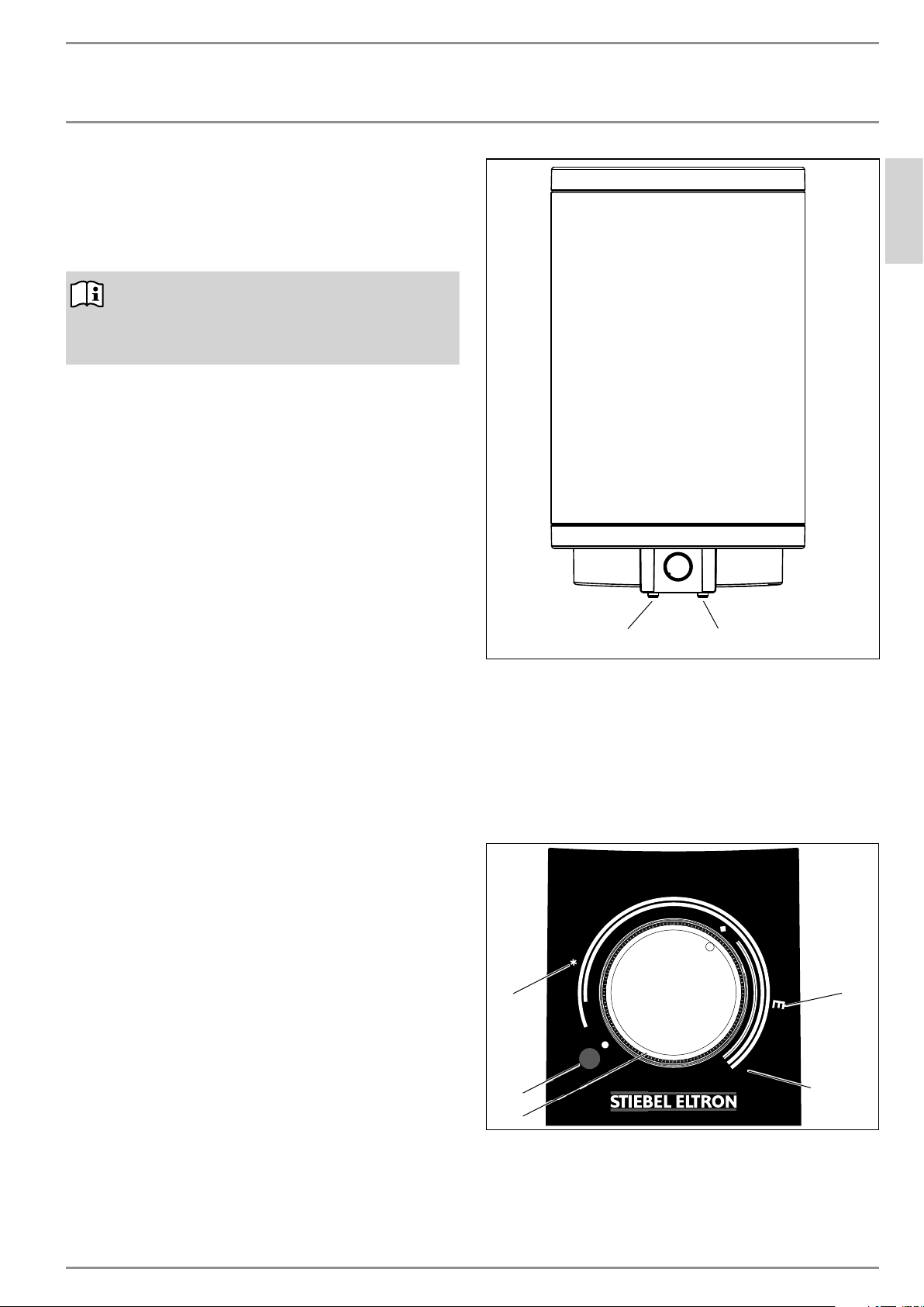
1
1 Hot water outlet stub
2 Cold water inlet stub
2
5. Settings
The temperature can be freely adjusted. It is factory set to 125 °F
(52 °C ).
Turn the knob clockwise to increase the temperature setting, and
counter-clockwise to decrease it.
3
max
1
2
1 ON/OFF indicator
2 Temperature knob
3 Frost protection
4 Recommended energy saving position, low scaling, 140 °F
(60 °C)
5 Maximum temperature setting, 167 °F (75 °C)
4
5
D0000037146
www.stiebel-eltron-usa.com PSH Plus | 5
INSTALLATION
Cleaning, care and maintenance
Depending upon the system, the actual water temperatures at the
tapping points may be lower than the set value.
WARNING Burns
There is a risk of scalding at outlet temperatures in
excess of 109 °F (43 °C).
Setting the temperature above 125 °F (52 °C) is not recommended without the installation of a mixing valve.
ON/OFF indicator
The ON/OFF indicator illuminates when water is being heated.
5.1 Vacation and absence
f If the appliance will not be used for a few days, set the tem-
perature knob to a position between the frost protection and
energy saving settings.
f If the appliance is not to be used for a longer period, set it to
frost protection to conserve energy. If there is no risk of frost
you may disconnect the appliance from the power supply.
f To protect against Legionella, heat the water once 140 °F
(60 °C) before using hot water again.
6. Cleaning, care and maintenance
f Have the electrical safety of the appliance and the func-
tion of the T&P relief valve regularly checked by a qualified
technician.
f Have the sacrificial anode initially checked by a qualified
technician after the first year. The qualified technician should
then determine the intervals at which it must be checked
thereafter.
f Never use abrasive or corrosive cleaning agents. A damp
cloth is sufficient for cleaning the exterior of the appliance.
7. Troubleshooting
Problem Cause Remedy
The water does not heat
up and the ON/OFF indicator does not illuminate.
The water does not heat
up sufficiently and the
ON/OFF indicator is illuminated.
The flow rate is low. The aerator in the tap or
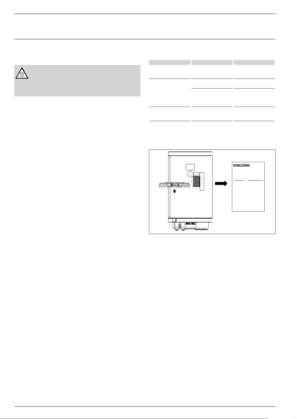
If you cannot remedy the fault, notify your qualified technician. To
facilitate and speed up your inquiry, please provide the numbers
from the type plate (000000 and 0000-000000):
There is no power.
The temperature is set
too low.
The appliance is heating,
for example, after large
amounts of DHW have
been drawn.
shower head is scaled up
or contaminated.
Check the fuses/circuit
breakers in your fuse
box.
Select a higher temperature.
Wait until the ON/OFF
indicator goes out.
Clean and/or descale the
aerator or shower head.
Made in EU
Hecho en EU
PSH XX Plus
M-NO.: 000000
S-NO.: 0000-000000
Technical data
Datos técnicos
Données techniques
Volume:
Volumen:
Volume:
Supply:
Alimentación:
Alimentation:
220-240 V AC, 60 Hz
SINGLE PHASE L-L ONLY
Power:
Potencia:
Puissance:
Fabriqué en EU
Max. pressure:
Presión máxima:
Pression max:
1 MPa / 145 PSI
Testing pressure:
Presión de prueba:
Pression d'essai:
1,5 MPa / 217 PSI
Standby loss:
Pérdida de calor:
Pertes en mode de veille:
Scaling
f Almost every type of water will deposit lime at high tem-
peratures. This settles inside the appliance and affects both
the performance and service life. The heating elements must
therefore be descaled from time to time. A qualified technician who knows the local water quality will tell you when
the next service is due. Contact the water supplier or local
plumbing inspector for additional information.
f Check the taps/faucets regularly. You can remove lime scale
deposits at the outlets using commercially available descaling agents.
f Regularly activate the T&P relief valve to prevent it from be-
coming blocked e.g. by lime scale deposits.
6 | PSH Plus www.stiebel-eltron-usa.com

INSTALLATION
Safety
INSTALLATION
8. Safety
Only a qualified technician should carry out installation, commissioning, maintenance and repair of the appliance.
8.1 General safety instructions
We guarantee trouble-free function and operational reliability only
if original accessories and spare parts intended for the appliance
are used and if the installation is performed as described in this
manual.
8.2 Instructions, standards and regulations
Note
Observe all applicable national, state and local regulations and instructions.
9. Appliance description
9.1 Standard delivery
The following are delivered with the appliance:
- T&P relief valve
9.2 Optional accessories
- PSH Plus drain pan [item no. 328651]
10. Preparations
Material losses
!
Mounting a water heater that does not meet the structural
requirement needed may lead to significant damage to
the water heater and the installation location.
Ensure that all fasteners used are of sufficient penetration
depth into a suitable material to support the full weight
of the appliance with an acceptable additional factor of
safety.
Before installing the appliance, ensure that the mounting location
will sufficiently hold the filled weight of the appliance with a factor
of safety of at least 50%. Consult a qualified installer or a structural engineer to evaluate whether the appliance can be safely
mounted in the desired location. Failure to properly evaluate the
installation location for structural integrity could result in damage
to the water heater and the installation location.
10.1 Installation site
The instructions below describe the mounting process for an
installation space with wooden studs. If the appliance will be
installed in a space without wooden studs, follow a similar construction procedure with comparable weight and loading considerations. Consult Stiebel Eltron for more information if you
are unsure about mounting the appliance with the materials you
have on hand.
16Ý
36Ý
6ÝVFUHZVSDFLQJ
DERYHZDOOEUDFNHW
ENGLISH
5
4
1
12ÝVFUHZVSDFLQJ
EHORZZDOOEUDFNHW
3
1 PSH Plus drain pan [item no. 328651]
The optional drain pan can be mounted below the appliance. The
drain pan will route away water from an activated T&P relief valve
or a leaking appliance.
1 Stud (wood, 16˝ on center)
2 ¾˝ plywood sheet
3 Wood screws (at least #10 x 2½˝ long)
4 PSH Plus
5 Tee nut, washer, & ½˝ bolt
www.stiebel-eltron-usa.com PSH Plus | 7
2
1
48Ý
INSTALLATION
Preparations
Note
Ensure that the temperature knob will be accessible from
the front when the appliance is secured in place.
The appliance is designed to be permanently wall-mounted to a
solid surface. Ensure the wall offers adequate load bearing capacity. Consult the specification table for the filled weight of your
appliance.
There should be a suitable drain near the appliance to drain off
water in the case of activation of the T&P relief valve.
Always install the appliance vertically in a room free from the risk
of freezing and as close as possible to the draw-off points.
The appliance may not be fitted in a corner since the screws for
fixing the appliance to the wall must remain accessible.
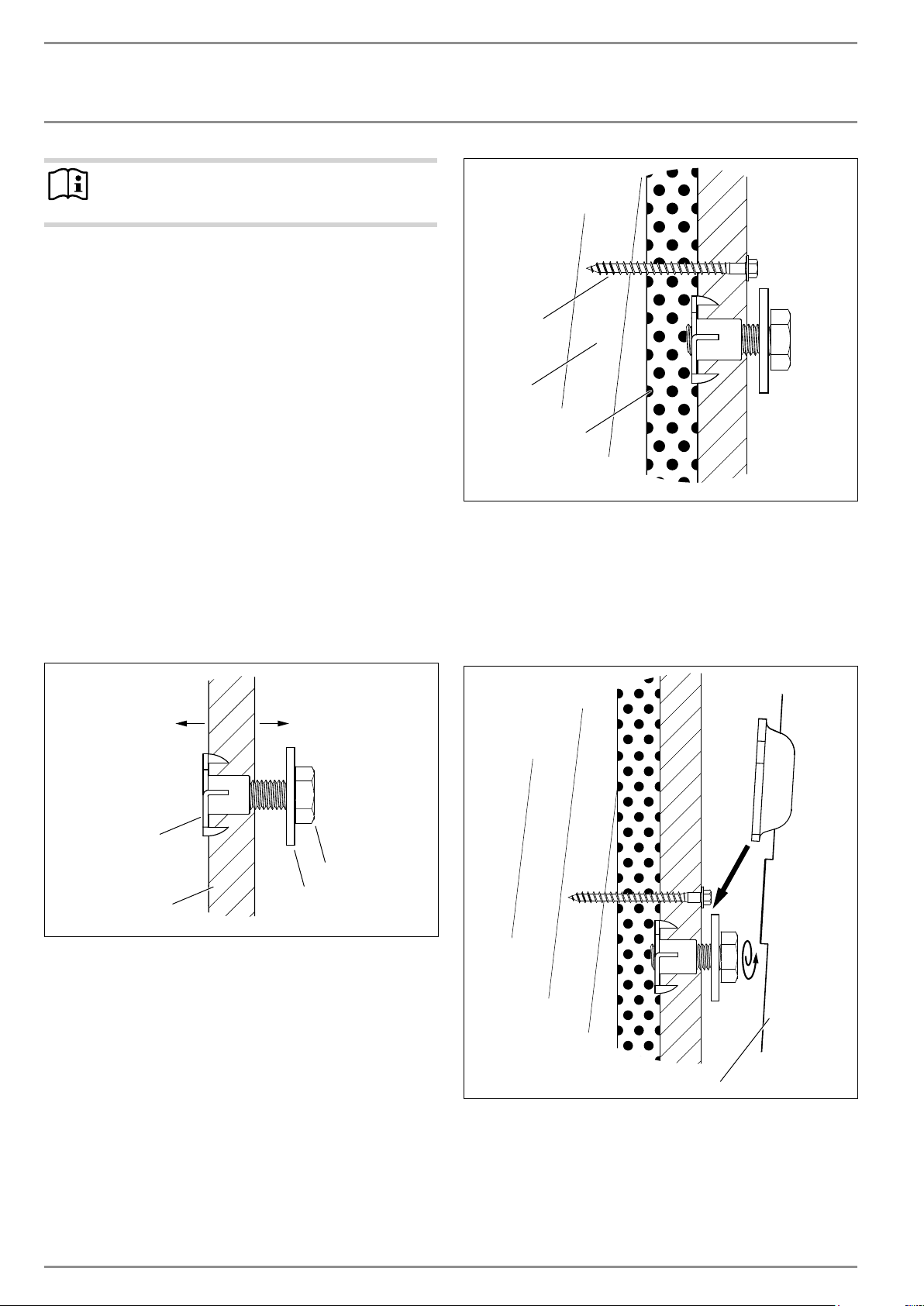
10.2 Securing the plywood backing sheet
This procedure calls for mounting a ¾˝ plywood sheet to the wall
attaching to at least 3 wooden studs, or another wall surface using
comparable means. Mount the appliance to the plywood sheet
using ½˝ diameter fasteners.
f Transfer the dimensions for the holes to be drilled on the ply-
wood sheet (see chapter 16.1, “Dimensions and connections”,
pg. 11).
f Drill a hole in the plywood to fit the ½˝ tee nuts into the back
side of the sheet. Thread the ½˝ bolt and washer into the tee
nut, leaving a gap for the tank to mount on.
7
6
5
5 ¾˝ drywall
6 2˝x6˝ stud
7 #10 x 2½˝ wood screw
10.3 Mounting onto the plywood backing sheet
The mounting bracket attached to the appliance has hook-in slots.
f Lift the appliance and mount it onto the ½˝ bolts. Make sure
the washers are on the outside of the mounting bracket.
To mounting
surface
3
4
1 ½˝ x 1¼˝ bolt
2 Washer
3 ½˝ tee nut
4 ¾˝ plywood
f Find the wall studs and mark their location. This is the most
secure means of mounting the sheet on the wall.
f Secure the plywood sheet to the studs with screws at least
size #10 x 2½˝ long. Space the screws every 6˝ above the
location of the tee nuts, and every 12˝ below. Use a level to
align the sheet horizontally.
f It is recommended to mount the plywood onto 2x6 studs, but
an installation on 2x4 studs is acceptable if mounted to at
least 3 studs. If studs are spaced farther apart than 16˝, use
a wider plywood sheet and make sure to mount to at least 3
studs.
To interior
space
1
2
1
1 PSH Plus
f Tighten the bolts onto the washer and the bracket.
8 | PSH Plus www.stiebel-eltron-usa.com
INSTALLATION
Installation
11. Installation
11.1 Water connection
Material losses
!
Carry out all water connection and installation work in
accordance with regulations.
Operate the appliance only with pressure-tested taps.
f Connect the hydraulic connections with flat gaskets or with
PTFE tape and pipe thread sealant. The connecting nipples
are bare steel. Use only brass or stainless steel unions or
adapters to connect directly to the tank.
11.1.1 Permissible materials
Material losses
!
When using plastic piping, observe the manufacturer's
data and use piping with very low oxygen permeability.
Cold water line
Only dielectric unions, brass or stainless steel connections can be
made directly to the cold and hot water line.
11.1.2 Fitting the T&P relief valve
Note
The supplied T&P relief valve must be used.
Note
If the water pressure is greater than 87 psi (0.6MPa),
install a pressure reducing valve in the "cold water inlet".
The maximum permissible pressure must not be exceeded (see
chapter 16.4, “Data table”, pg. 13).
f Please note that, depending on the static pressure, you may
need a pressure reducing valve.
f Size the drain so that water can drain off unimpeded when
the T&P relief valve is fully opened.
f Fit the discharge pipe of the T&P relief valve with a constant
downward slope and in a room free from the risk of frost.
f The safety valve discharge opening must remain open to the
atmosphere. Do not immerse in water.
11.2 Power supply
Material losses
!
Observe the type plate. The specified voltage must match
the mains voltage.
12. Commissioning
12.1 Commissioning
Note
Fill the appliance with water prior to electrical connection. If you switch on the appliance while empty, the high
limit safety cut-out will activate and need to be reset.
f Thoroughly flush out the cold water line before connecting
the appliance, so that no foreign material gets into the water
heater or T&P relief valve.
f Open the shut-off valve in the cold water feed line.
f Open a draw-off point until the appliance has filled up and
the piping is free of air.
f Turn the temperature knob to maximum.
f Switch the on the circuit breaker connected to the appliance.
f Check the function of the appliance. Turn the temperature
knob down to the minimum setting. Ensure that the thermostat switches off.
f Turn the temperature knob back to the energy saving setting.
f Check that the T&P relief valve is working correctly.
12.1.1 Appliance handover
f Explain the function of the appliance and T&P relief valve to
users and familiarize them with their operation.
f Make users aware of potential dangers, especially the risk of
scalding.
f Hand over these instructions.
12.2 Recommissioning
See chapter 12.1, “Commissioning”, pg. 9.
13. Shutting down
f Disconnect the appliance from the mains at the circuit break-
er/fuse. If possible, lock out the breaker so that it cannot be
accidentally activated.
f Drain the appliance. See chapter 15.1, “Draining the appli-
ance”, pg. 10.
ENGLISH
WARNING Electrocution
Carry out all electrical connection and installation work
in accordance with relevant regulations.
Only use a permanent connection to the power supply.
The appliance must be able to be separated from the
power supply by a circuit breaker that disconnects all
poles. Before any work on the appliance, disconnect all
poles from the power supply. Ensure that the appliance
is grounded.
www.stiebel-eltron-usa.com PSH Plus | 9
14. Troubleshooting
Note
The high limit safety cut-out can activate at temperatures
below 5 °F (–15 °C). The appliance may be subjected to
these temperatures during storage or transport. If the
appliance does not heat during the initial commissioning,
the high limit safety cut-out switch may need to be reset.

INSTALLATION
Maintenance
Fault Cause Remedy
The water does not heat
up and the ON/OFF indicator does not illuminate.
The water does not heat
up and the ON/OFF indicator illuminates.
The water does not heat
up sufficiently and the
ON/OFF indicator illuminates.
The heat-up time is very
long and the ON/OFF indicator illuminates.
The T&P relief valve drips
when heating is switched
off.
The high limit safety
cut-out has responded
because the controller is
faulty.
The high limit safety
cut-out has responded
because the temperature
has fallen below 5 °F
(-15 °C) .
The heating element is
faulty.
The temperature controller is faulty.
The heating element is
scaled up.
The valve seat is contaminated.
Water pressure is too
high.
An expansion vessel was
not installed.
Remedy the cause of the
fault. Replace the controller.
Press the reset button
(see diagram).
Replace the heating element.
Replace the temperature
controller.
Descale the heating element.
Clean the valve seat.
Install a pressure reducing valve.
Install an expansion
vessel in line with the
appliance (see plumbing
schematic).
Reset key, high limit safety cut-out
If the high limit safety cut-out has activated, it should be reset.
Shut off the circuit breaker connected to the appliance before
removing the bottom cover and resetting the switch.
15.1 Draining the appliance
WARNING Burns
Hot water may escape during the draining process.
If is necessary to drain the cylinder for maintenance or to protect
the whole installation from freezing, proceed as follows:
f Close the shut-off valve in the cold water feed line.
f Open the DHW valves of all draw-off points until the appli-
ance is fully drained.
f Drain any residual water from the T&P relief valve.
15.2 Checking / replacing the sacrificial anode
f Check the sacrificial anode after the first year of use and re-
place if necessary.
f Next, decide the time intervals at which further checks
should be carried out.
15.3 Descaling
f Remove loose scale deposits from the water heater.
f If necessary, descale the inner cylinder with commercially
available descaling agents.
f Only descale the flange after disassembly and never treat the
cylinder surface and sacrificial anode with descaling agents.
15.4 Anti-corrosion protection
Ensure that while carrying out maintenance work the anti-corrosion protection resistor (560 Ω) is not damaged or removed.
Reinsert the anti-corrosion protection correctly after replacement.
15. Maintenance
WARNING Electrocution
Carry out all electrical connection and installation work
in accordance with relevant regulations.
Before any work on the appliance, disconnect all poles
of the appliance from the power supply.
If you need to drain the appliance, observe chapter 15.1, “Draining
the appliance”, pg. 10.
10 | PSH Plus www.stiebel-eltron-usa.com
15.5 Replacing the power cable
DANGER Electrocution
The power cable must only be replaced (for example if
damaged) by a qualified technician.
 Loading...