

Stiebel Eltron 234047, 234050 Installation Manual
Operation and Installation
Guía De Funcionamiento e Instalación
Mode D’emploi et Manuel D’installation
Wall-Mounted Infrared Room Heater | Calefactor Infrarrojo Montado en la Pared |
Chauffage Infrarouge à Montage Mural
»SunWarmth™ CIR 150-1 I
»SunWarmth™ CIR 150-1 O
»SunWarmth™ CIR 200-2 O
»SunWarmth™ CIR 400-2 O
Conforms to ANSI/UL Std. 2021
Certifi ed to CAN/CSA Std. 22.2 No. 46
Conforme a ANSI/UL Std. 2021
Certifi cación con CAN/CSA Std. 22.2 No. 46
Conforme à la norme ANSI/UL Std. 2021
Certifi é à la norme CAN/CSA Std. 22.2 No. 46
STIEBEL ELTRON, Inc.
17 West Street | West Hatfi eld, MA 01088
Tel. 413-247-3380 | Fax 413-247-3369
Email info@stiebel-eltron-usa.com
www.stiebel-eltron-usa.com

CONTENTS | OPERATION
IMPORTANT INSTRUCTIONS
OPERATION
1. Important instructions _________________________________________2
1.1 Document information ____________________________________________ 3
1.2 Key to symbols ______________________________________________________ 3
2. Safety ____________________________________________________________3
2.1 Minimum required clearances ___________________________________ 3
2.2 Intended use _________________________________________________________ 4
2.3 Safety information _________________________________________________ 4
2.4 ETL / UL / CSA designation _______________________________________ 4
3. Register your product __________________________________________4
4. Appliance description __________________________________________4
5. Operation _______________________________________________________5
5.1 Starting the heater _________________________________________________ 5
5.2 Shutting down the heater_________________________________________ 5
6. Cleaning, care and maintenance ______________________________5
6.1 Maintenance _________________________________________________________ 5
6.2 Cleaning ______________________________________________________________ 5
7. Safety ____________________________________________________________5
7.1 General safety instructions _______________________________________ 5
7.2 Instructions, standards and regulations _______________________ 5
8. Appliance description __________________________________________5
8.1 Standard delivery ___________________________________________________ 5
INSTALLATION
9. Installation ______________________________________________________6
9.1 Project design considerations & guidelines ___________________ 6
9.2 General installation instructions ________________________________ 6
9.3 Locating the heater_________________________________________________ 7
9.4 Mounting the heater _______________________________________________ 7
9.5 Minimum required clearances ___________________________________ 7
9.6 Power supply ________________________________________________________ 8
9.7 Heat lamp replacement ___________________________________________ 9
10. Appliance handover __________________________________________ 15
11. What to do if ... _______________________________________________ 15
12. Specifi cation ___________________________________________________ 15
12.1 Recommended mounting and coverage specifi cations ____15
12.2 Wiring diagrams ___________________________________________________ 15
12.3 Dimensions _________________________________________________________ 16
12.4 Specifi cation table _________________________________________________ 17
13. Spare Parts ____________________________________________________ 17
14. Warranty _______________________________________________________ 18
OPERATION
1. Important instructions
Save these instructions
When using electrical appliances, basic precautions should always
be followed to reduce the risk of fi re, electric shock, injury to
persons or death, and property damage including the following:
1 This heater must be installed only by a qualifi ed electrician.
Read and understand all instructions before installing, using
or servicing this heater. Improper installation, operation,
adjustment, alteration, service or maintenance can result in
the risk of fi re and electrical shock, and may cause property
damage, injury or death.
2 This heater is hot when in use. To avoid burns, do not let
bare skin touch hot surfaces. Keep electrical cords and
combustible materials, such as furniture, pillows, bedding,
papers, clothes, etc. and curtains at least 3 feet (1 m) from
the front of the heater and keep them at least 3 feet (1 m)
away from the sides and rear.
3 Extreme caution is necessary when any heater is used by or
near children or invalids.
4 Never leave the heater unattended during operation. Unplug
120 V models or turn off circuit breaker(s) on 240 V models if
not in use.
5 Do not operate any heater with a damaged cord or plug,
or after the heater malfunctions, or if it has been dropped
or damaged in any manner. Return heater to an authorized
service facility for examination, electrical or mechanical
adjustment, or repair.
6 These heaters are not for use in bathrooms, laundry areas,
and similar indoor locations. Never locate heater where it
may fall into a bathtub or other water container.
7 Model CIR 150-1 I is for indoor use only. Do not use this
model outdoors or in wet environments. Models CIR 150-1 O,
CIR 200-2 O, and CIR 400-2 O may be used outdoors or in wet
environments.
8 Do not run cord under carpeting. Do not cover cord with
throw rugs, runners, or the like. Arrange cord away from
traffi c areas where it will not be tripped over.
9 Arrange the cord at the side and back of the heater - do not
allow cord to drape over the heater.
10 To disconnect heater remove plug from outlet (120 V models)
or switch off at power source (240 V models).
11 120 V models CIR 150-1 I and CIR 150-1 O must be connected
to a 120 V outlet that is properly grounded and controlled by
a timer switch.
12 240 V models must be hard wired to a circuit that is properly
grounded and controlled by a timer switch. Copper wire is
required.
13 Do not insert or allow foreign objects to enter the heater
or any ventilation or exhaust opening as this may cause an
electric shock, fi re, or damage the heater. Death, personal
injury or property damage could result.
14 To prevent a possible fi re, do not block air intakes or exhaust
in any manner. Do not use on a soft surface, like a bed,
where openings may become blocked.
2 |SUNWARMTH™ CIR INFRARED HEATER WWW.STIEBEL-ELTRON-USA.COM
OPERATION
SAFETY
15 Use this heater only as described in this manual. Any other
use not recommended by the manufacturer may cause fi re,
electric shock, and death or injury to persons and property
damage.
16 With 120 V models, avoid the use of an extension cord
because the extension cord may overheat and cause a risk of
fi re. IMPORTANT: However, if you have to use an extension
cord, the cord shall be No. 14 AWG minimum size and rated
for not less than 1875 watts.
17 Do not touch an operating heater or live parts - burns,
electric shock and death or personal injury can result.
18 All CIR models must be installed on a timer or timer switch.
Consult local electrician/installer for installation details.
19 Do not adjust the heater on the swivel bracket during
operation. Allow heater to completely cool before making
any adjustment to the heater position.
20 Do not stare at the heater lamp - damage to your eyes could
occur.
21 After use, allow the heater to cool down before touching,
moving, or storing.
22 These instructions belong with the heater for ready
reference. Keep this manual in a safe place near the heater.
1.1 Document information
The chapter Operation is intended for users and qualifi ed installers.
The chapter Installation is intended for qualifi ed installers.
Read these instructions carefully before using the
appliance and retain them for future reference. Pass
on the instructions to any new users.
1.2 Key to symbols
1.2.1 Layout of safety information
Safety information comprises a warning symbol, a keyword
text with information. Safety information is printed on a grey
background.
Example:
12 3
DANGER: Electrocution
Install the appliance in such a way that control
equipment...
1.2.3 Information on the appliance
Never cover the appliance
1.2.4 Units of measurement
The dimensions in this document are given in in. (cm).
Any alternative units of measurements are specifi ed
accordingly.
2. Safety
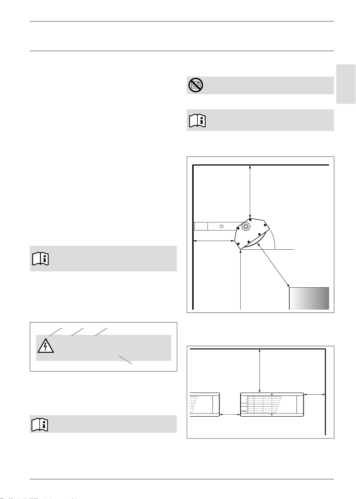
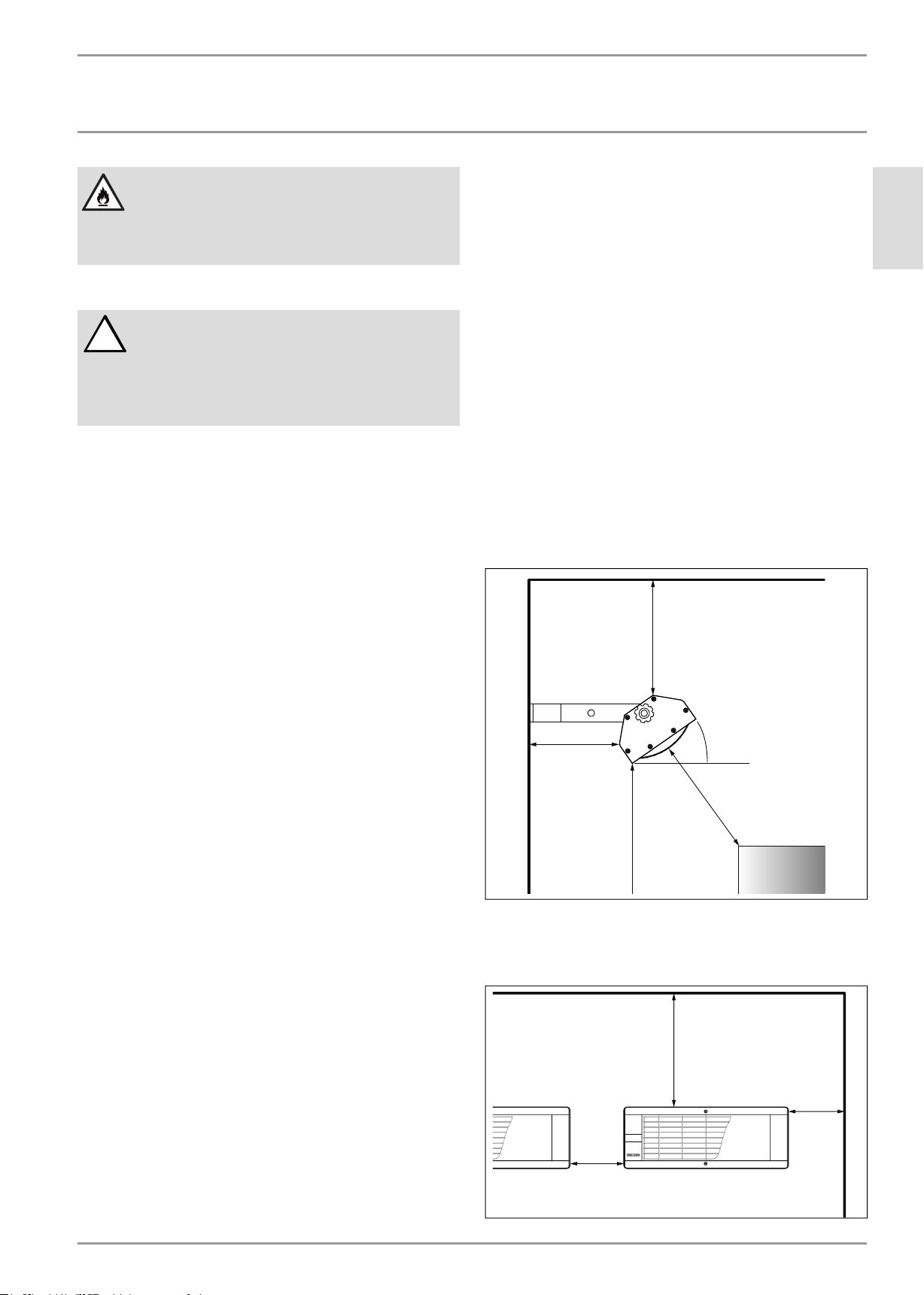
2.1 Minimum required clearances
12ÝFP
°°
4ÝFP
For mounting
height, see “12.1
Recommended
mounting and
coverage specifi ca-
tions” on page 15
Do not place anything closer than 36˝ (92 cm) in front of or below
the heater.
Fasten brackets to structural member (or equivalent strength and
integrity) of a non-combustible wall surface.
PLQÝFP
ENGLISH
4
1 Symbol
2 Keyword
3 Description
4 Information text
1.2.2 Text symbols and layout in this documentation
Read the text next to this “»” symbol carefully.
» The "»" symbol indicates that you should do something. The
action you need to take is described step by step.
— Passages with the "–" symbol show you lists of items.
WWW.STIEBEL-ELTRON-USA.COM SUNWARMTH™ CIR INFRARED HEATER| 3
PLQÝFP
12ÝFP
PLQÝFP
OPERATION
REGISTER YOUR PRODUCT
2.2 Intended use
This appliance is designed to heat living areas. Model CIR 150-1
I is for indoor use only. Models CIR 150-2 O, CIR 200-2 O and CIR
400-2 O are for outdoor or indoor use.
Any other use beyond that described shall be deemed
inappropriate. Correct use of this appliance also includes following
all instructions in this manual. Any modifi cations or conversions
to the appliance void all warranty rights.
2.3 Safety information
Only operate the appliance when fully installed by a licensed
electrician and with all safety equipment fi tted.
WARNING: Fire
Never operate this appliance ...
— in rooms where the appliance is at risk of fi re or
explosion as a result of chemicals, dust, gases or
vapors.
— in the direct proximity of pipes or receptacles that
carry or contain fl ammable or explosive materials.
— if work such as laying cables, grinding or sealing
is carried out in the installation room.
— if sprays, fl oor polish or similar products
containing gasoline are used. Vent the room
suffi ciently before heating.
— if the minimum clearances to adjacent object
surfaces are not maintained, for example to
furniture, net curtains, curtains, textiles or other
fl ammable materials (for minimum clearances, see
drawing above).
— if an appliance component is damaged, the
appliance has fallen over or already had a fault.
WARNING: Injury
Where children or persons with limited physical,
sensory or mental capabilities are allowed to control
this appliance, ensure that this will only happen under
supervision or after appropriate instructions by a
person responsible for their safety.
Children must be supervised and instructed to ensure
that they never play with the appliance.
WARNING: Fire
Never place any fl ammable, combustible or insulating
objects or materials, such as laundry, blankets,
magazines, containers with fl oor polish or petroleum
products, spray cans or similar on the appliance or in
direct proximity to it.
WARNING: Fire
Never leave the heater unattended during operation.
Heater must be installed on a timer switch. Unplug
120 V models or turn off circuit breaker(s) on 240 V
models if not in use.
WARNING: Electrocution
Always disconnect the heater from the power source
prior to servicing. Failure to do so may result in serious
bodily injury or death.
Do not use or locate the appliance where it could fall
into a bathtub or other water container.
WARNING: Burns
The surfaces of the appliance casing become hot
during operation. Do not touch this appliance while
in operation. Allow to completely cool after use and
before touching.
CAUTION: Overheating
Never cover the appliance
2.4 ETL / UL / CSA designation
The ETL / UL designation shows that the appliance meets all
essential requirements according to ANSI/UL 1278 or 2021 and
CAN/CSA C22.2 No.46.
2.4.1 Type label
See type plate. The type plate is located on the top in the center
of the exterior of the appliance.
3. Register your product
You must register this product within 90 days of
purchase on our web site in order to activate any
standard warranty or to be eligible for the extended
warranty. Go to our website at:
www.stiebel-eltron-usa.com and click on “Register
Your Product.”
Before beginning the registration process, we suggest that you
gather the necessary information as follows:
Type, Example: CIR 150-1 I (from the label that is on the top of
the unit in the center)
Number listed after “Nr.”
Place of Purchase
Purchase Date
First & Last Name
Email address
Physical Address
Phone Number
If you have any questions concerning the registration process
or warranty options, please contact Stiebel Eltron USA directly
at (800)-582-8423.
4. Appliance description
The appliance is a radiant heater that uses short-wave infrared
light. It is designed to heat objects, not the air in the space. It is
designed for installation on a wall or post.
All models are suitable as a spot heating system for indoor living
areas such as garages or workshops, or for livestock. Note: Model
CIR 150-1 I is for indoor use only! Models CIR 150-1 O, CIR 200-2
O, and CIR 400-2 are also suitable for spot heating outdoor living
areas, for example, patios, balconies and decks.
The radiant heater casing is made of aluminum. The protective
grill and screws are made from stainless steel.
4 |SUNWARMTH™ CIR INFRARED HEATER WWW.STIEBEL-ELTRON-USA.COM
OPERATION
OPERATION
5. Operation
WARNING: Fire
Never leave the heater unattended during operation.
Heater must be installed on a timer switch. Unplug
120 V models or turn off circuit breaker(s) on 240 V
models if not in use.
5.1 Starting the heater
» For 120 V models, plug the unit into a grounded electrical
outlet connected to a timer switch. Set timer switch for desired
operating time.
» For 240 V models, turn on the circuit breaker(s) the unit is
connected to. Set timer switch for desired operating time.
5.2 Shutting down the heater
» For 120 V models, turn off unit at timer switch and unplug the
unit’s cord from the wall outlet.
» For 240 V models, turn off unit at timer switch and power at the
circuit breaker panel.
6. Cleaning, care and maintenance
WARNING:
!
Before cleaning, make sure the power has been turned
off at the circuit breaker panel or unplugged from the
wall outlet, and that the heating element of the heater
is cool. Ensure power remains disconnected during
entire installation. Failure to do so could result in
serious burns, electrocution, serious bodily injury, or
death.
6.1 Maintenance
» Inspect the heater and cord prior to each use.
» Clean any accumulation of dust or dirt from surfaces and in
particular from the refl ector and any air openings in the heater
body (see “6.2 Cleaning” on page 5).
» Inspect the electrical cord and plug for damage or fraying:
— Do not operate the heater with a damaged cord or plug.
— Do not use any abrasive or caustic cleaning agents.
— Never immerse the appliance in water! Danger to life!
— If a heater is exposed to water beyond the intended use of
outdoor models, have a qualifi ed electrician inspect and
repair the heater prior to use.
— As part of regular maintenance, we recommend also having
the control components checked. The safety and control
components should be checked by a contractor no more than
ten years after commissioning.
7. Safety
Only qualified contractors should carry out installation,
commissioning, maintenance and repair of the appliance.
7.1 General safety instructions
We guarantee trouble-free function and operational reliability
only if the original accessories and spare parts intended for the
appliance are used.
DANGER: Electrocution
If you mount the appliance on the wall, do so in such
a way that control equipment cannot be touched by a
person in the bath or shower.
CAUTION:
!
— Observe the minimum clearances to adjacent
object surfaces (see “9.5 Minimum required
clearances” on page 7).
— Never install the appliance directly below a wall
socket.
— Ensure that the power cable is not in contact with
any appliance components.
7.2 Instructions, standards and regulations
Observe all applicable national and regional regulations
and instructions.
8. Appliance description
ENGLISH
— Have damaged parts replaced by a qualifi ed electrician.
» Any damaged parts or components must be repaired or replaced
prior to operation.
6.2 Cleaning
CAUTION: Fire
Never spray cleaning spray into the refl ector or any
openings.
Ensure that no moisture can enter the appliance.
— Before cleaning, disconnect the heater from the power supply
and allow to cool.
— Do not touch the heat lamp with your fi ngers - oil from your
skin will damage the lamp.
— To clean the heater surface, refl ector, and air inlets: Use only
a dry or damp cloth or low pressure air stream (computer
‘duster’ in a can).
WWW.STIEBEL-ELTRON-USA.COM SUNWARMTH™ CIR INFRARED HEATER| 5
8.1 Standard delivery
—Heater unit
— Wall mounting bracket including fi xing screws, locking
washers and nut
INSTALLATION
INSTALLATION
INSTALLATION
9. Installation
9.1 Project design considerations & guidelines
NOTE: All CIR Infrared Heaters must be installed on a
timer or timer switch.
NOTE: Refer to “9.5 Minimum required clearances”
on page 7 regarding the minimum required
clearances.
The size and quantity of heaters (amount of heat input) required
over an area to provide comfort is affected by the following factors:
9.1.1 General:
— Amount of air movement in the area: “wind chill” requires
additional heat input
—Provide wind breaks wherever possible
— “Spot heating” comfort is most effective if people are heated
from at least two sides
— Available mounting height for heaters at the project site
9.1.2 Indoor application:
— “Space heat” the entire structure (accurate heat loss
calculation required. For assistance contact Stiebel Eltron at
800-582-8423 or info@stiebel-eltron-usa.com), or
— “Spot heat” only part of a cold indoor area
» Input formula = Site Length x Site Width x Temperature Rise x
Heat Density per Degree
Example:
— Outdoor patio: 30 feet long by 10 feet wide
— Desired temperature rise: 20°F (average over the area)
— 30 x 10 x 20 x 2 = 12,000 Watts total input required
Compare the values of the available mounting height and area
dimensions at the project site to the recommended mounting
heights, length and width of coverage area, and typical average
he at dis tribut ion in “9. 1 Pr oje ct design considerations & guidelines”
on page 6.
Layout:
— Space the heaters uniformly around the perimeter (and if
required, in the center or throughout the area) to provide
suffi cient heat density to accomplish the desired temperature
rise or spot heat only specifi c locations within the area.
— Provide heat from at least two sides wherever possible
NOTE: The design information presented here is
intended as a guideline. The accuracy of determining
or estimating all factors above will affect performance
and satisfaction. Air movement in particular will
affect comfort.
9.2 General installation instructions
NOTE: Read all instructions and plan the installation
before proceeding.
— The activity level of the people: seated at rest, hard physical
labor, etc.
9.1.3 Outdoor application:
NOTE: MODEL CIR 150-1 I IS FOR INDOOR USE ONLY!
— Any area heated outdoors is “spot heat”
— Models CIR 150-1 O, CIR 200-2 O, and CIR 400-2 O are for
indoor or outdoor use
» Desired temperature rise:
— In what seasons is comfort required and what is the outside
design temperature?
— Then what temperature rise is desired for comfort? (10°, 15°,
20°, 25°)
» Calculate the required input to get the desired average
temperature rise:
Input Required per Area per Degree Comfort Temperature Rise
Heat density
per degree F
W/(ft2)/°F
Outdoor heating
(up to 10 mph wind) 2 40
Indoor spot heating
(protected area, low
air movement) 0.75 14
Heat density
per degree C
W/(m2)/°C
This appliance conforms to ANSI/UL 1278 or 2021 and is certifi ed
to CAN/CSA C22.2 No.46.
The model CIR 150-1 I is approved for indoor use only. Do not
use this heater in environments such as bathrooms and laundry
rooms. The heater is supplied with an 8 ft (2.4 m) cord with a three
prong plug that must connect to a properly grounded 115–120 V
outlet on a copper wire electrical supply circuit controlled by a
timer switch.
Models CIR 150-2 O, CIR 200-2 O and CIR 400-2 O are approved for
outdoor and indoor use. Do not use these heaters in environments
such as bathrooms and laundry rooms. These models must be
connected to a properly grounded 240 V copper wire electrical
supply circuit(s) controlled by a timer switch. Installation must
conform with the latest edition Electrical Code ANSI/NFPA N0 70
in the U.S.A. and PART 1 CSA C22.1 in Canada.
A mounting bracket suitable for a wall or post is supplied with
the heater. The heater must be mounted to this bracket during
operation. Hardware to fasten the mounting bracket to the
structure is determined by site conditions, and is fi eld supplied
by the installer.
WARNING: Fire
When installing models CIR 150-1 I or CIR 150-1 O avoid
the use of an extension cord because the extension
cord may overheat and cause a risk of fi re. However,
if you must use an extension cord, the cord shall be
No. 14 AWG minimum size and rated not less than 1875
Watts.
6 |SUNWARMTH™ CIR INFRARED HEATER WWW.STIEBEL-ELTRON-USA.COM
INSTALLATION
INSTALLATION
WARNING: Fire
Always maintain the minimum clearances from the
fl oor, ceiling, side walls, and combustible materials.
Refer to “9.5 Minimum required clearances” on page
7.
9.3 Locating the heater
WARNING:
!
Use of this heater in coastal salt-air regions can result
in corrosion of the aluminum body and refl ector, and
premature failure of the heat lamp. Corrosion and
failure resulting from use in coastal areas is not
covered by warranty.
1 The heater is designed for wall or post mounting and must
be installed at a minimum height above the fl oor. See “12.1
Recommended mounting and coverage specifi cations” on
page 15 for details.
2 Ensure that clearances from the heater meet or exceed the
minimum required clearances in “9.5 Minimum required
clearances” on page 7: Above; to the Floor; to a Side wall;
and to combustible materials.
3 Models CIR 150-1 I and CIR 150-1 O must plug in to a
properly grounded 120 V outlet controlled by a timer switch.
Ensure the electrical outlet is readily accessible to be able to
disconnect the heater when needed.
Models CIR 200-2 must be connected to a properly grounded
240 V copper wire circuit controlled by a timer switch.
Model CIR 400-2 O must be connected to two (2) independent
grounded 240 V copper wire circuits controlled by a timer
switch.
4 The heater should never be placed nor mounted directly
under a wall electrical outlet.
5 A minimum distance of 36˝ (92 cm) must be maintained
between the front grille and fl ammable items (e.g. curtains),
walls and other structures.
6 Do not allow an electrical cord to pass in front of the heater
or to touch any hot surface.
7 Since the appliance radiates heat, no obstruction or object
such as furniture should be placed between the heater and
the person being heated.
8 Do not use heater on a soft surface, like a bed, where air
openings may become blocked.
9 A heater has hot surfaces and potentially arcing or sparking
parts inside. Do not use in areas where gasoline, paint, or
fl ammable vapors or liquids are used or stored.
4 Models CIR 150-1 I and CIR 150-1 O: If at all possible, locate
the mounting bracket so that the electrical cord 8’ (2.4 m) can
be plugged into an electrical outlet (grounded 120 V) without
stretching the electrical cord taut. See important notice (“9.2
General installation instructions” on page 6) regarding
the use of an extension cord.
5 Never allow an electrical cord to pass in front of the heater or
to come into contact with any hot surface of the heater.
6 The mounting bracket fastens to the structure using fi eld
supplied bolts or lag screws through two holes in one side
of the bracket. The heater bracket fastens to the mounting
bracket through the outermost hole on the other leg of
the mounting bracket using the bolt, lock washer and nut
supplied.
7 Fasten the mounting bracket plumb and level so that the
heater is oriented horizontally on the long axis.
8 Ensure that the mounting bracket is fi rmly fastened to the
structure with bolts or lag screws (fi eld supplied) of suffi cient
strength and integrity to support the weight and prevent
movement of the heater. It is recommended to fasten the
mounting bracket to a structural member (wall stud, etc.).
9.5 Minimum required clearances
12ÝFP
°°
4ÝFP
Mounting height
“12.1 Recommend-
ed mounting and
coverage specifi ca-
tions” on page 15
Do not place anything closer than 36˝ (92 cm) in front of or below
the heater.
Fasten brackets to structural member (or equivalent strength and
integrity) of a non-combustible wall surface.
PLQÝFP
ENGLISH
9.4 Mounting the heater
1 Mount the heater securely to a surface or structural member,
and maintain at least all minimum clearances indicated in
“9.5 Minimum required clearances” on page 7.
2 Use the mounting bracket supplied with the heater - see “9.5
Minimum required clearances” on page 7.
3 Hardware to fasten the mounting bracket to the structure
is fi eld supplied by the installer since the type of hardware
fastening is determined by site conditions.
PLQÝFP
WWW.STIEBEL-ELTRON-USA.COM SUNWARMTH™ CIR INFRARED HEATER| 7
12ÝFP
PLQÝFP
INSTALLATION
m
INSTALLATION
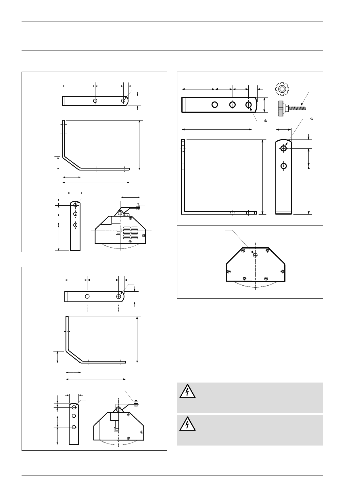
Mounting Bracket for CIR 150-1 I and CIR 150-1 O
1/2Ý
(1.3 cm)
2 1/2Ý
(6.3 cm)
1 5/8Ý
1 3/16Ý
(3 cm)
1 1/2Ý
(3.8 cm)
(4.2 cm)
3/8Ý
(1 cm)
4 5/16Ý
(11.0 cm)
1 5/8Ý
(4.2 cm)
1 1/4Ý
(3.2 cm)
8Ý
(20.3 cm)
Ø8.5 mm
3 1/8Ý
(8 cm)
3-Ø13mm
1 1/4Ý
6 11/16Ý
(17.0 cm)
(3.2 cm)
M8
Mounting Bracket for CIR 400-2 O
1 9/16Ý
13 3/16Ý
(9.7 cm)
1 9/16Ý
(4 cm)
7 1/2Ý
(19 cm)
Ø8 mm
(4 cm)
1/2Ý
(1.3 cm)
1 1/4Ý
8
7 1/2Ý
(19 cm)
(3.2 cm)
1 1/4Ý
(3.2 cm)
M8
1/2Ý
8 m
(1.3 cm)
(4 cm)
Ý
Ý
(13.7 cm)
3 5/8Ý
(9.25 cm)
Mounting Bracket for CIR 200-2 O
2 15/16Ý
(7.5 cm)
1 5/8Ý
(4.2 cm)
1 3/16Ý
(3 cm)
1 1/2Ý
(3.8 cm)
2 7/8Ý
3/8Ý
(1 cm)
(7.25 cm)
1 5/8Ý
(4.2 cm)
1 1/4Ý
(3.2 cm)
6 5/8Ý
(16.8 cm)
Ø8.5 mm
3 1/8Ý
(8 cm)
1/2Ý
(1.3 cm)
3-Ø13 mm
1 1/4Ý
(15 cm)
5 15/16Ý
M8
(3.2 cm)
1 Attach the heater bracket to the mounting bracket (outermost
hole), using the bolt, lock washer and nut supplied. Tighten
securely.
2 The bracket attached to the top of the heater allows rotation
up to 45° on the short axis by loosening the attachment bolt.
3 Once heater position is established, tighten all nuts and bolts
at mounting and heater bracket connections to maintain the
heater in a secure and stable position.
4 Read and follow all warnings, and the following section on
Operation to enjoy safe operation of the heater.
9.6 Power supply
DANGER: Electrocution!
Carry out all electrical connection and installation
work in accordance with all national, state and local
building code.
DANGER: Electrocution!
Each 240 V heater must be wired directly to a circuit
with a timer switch and the proper size breaker and
wire gauge.
8 |SUNWARMTH™ CIR INFRARED HEATER WWW.STIEBEL-ELTRON-USA.COM

INSTALLATION
INSTALLATION
DANGER: Electrocution!
Do not plug models CIR 200-2 O or CIR 400-2 O into
a wall outlet.
NOTE: The specifi ed voltage on the nameplate must
match the voltage at the circuit breaker panel.
Electrical connection must be performed by a qualifi ed electrical
tradesperson. Installation must conform with the latest edition
Electrical Code ANSI/NFPA N0 70 in the U.S.A. and PART 1 CSA
C22.1 in Canada.
9.6.1 CIR 150-1 I and CIR 150-1 O
Plug heater into a properly grounded wall outlet connected to a
120 V, 60Hz, 20 Amp copper wire circuit that is properly grounded
and controlled by a timer switch.
9.6.2 CIR 200-2 O
Using 12 AWG copper wire, connect the heater to a 240 V, 60Hz,
15 Amp circuit breaker that is properly grounded and controlled
by a timer switch.
9.6.3 CIR 400-2 O
Using 12 AWG copper wire, connect the heater with a timer switch
to each of two independent 240 V, 60Hz, 15 Amp circuit breakers
that are each properly grounded.
ENGLISH
2 Remove end cover at both ends of heater. Six (6) Phillips
screws hold the end cover in place. Remove the screws to
secure storage:
9.7 Heat lamp replacement
WARNING:
!
Heater service should only be performed by a qualifi ed
electrician. Failure to comply could result in personal
injury, death, fi re and/or property damage. Tampering
with the heater by an unqualifi ed person will void the
warranty.
WARNING:
!
Before servicing, make sure the power has been turned
off at the circuit breaker panel or unplugged from the
wall outlet, and that the heating element of the heater
is cool. Ensure the power remains disconnected the
entire time the unit is being serviced. Failure to do so
could result in serious burns, electrocution, serious
bodily injury, or death.
CAUTION:
!
Always wear cotton or other fabric gloves when
replacing heat lamp.
Do not touch the lamp surface with your bare hands.
Oils from your skin will cause damage to the lamp.
The heater requires some disassembly to access electrical
connections when replacing the lamp.
Use a container to securely store disassembled components and
screws.
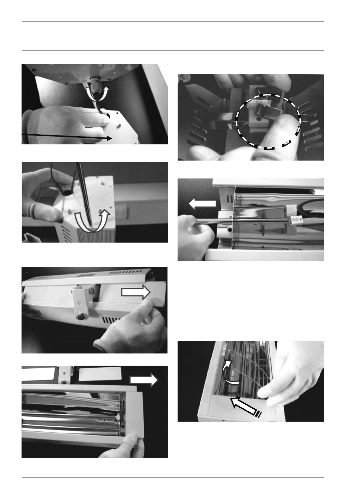
3 Slide out the face plate at each end of heater to expose both
ends of the heat lamp:
4 Turn heater face down, and slide the center cover plate and
the heater mounting bracket out of the heater:
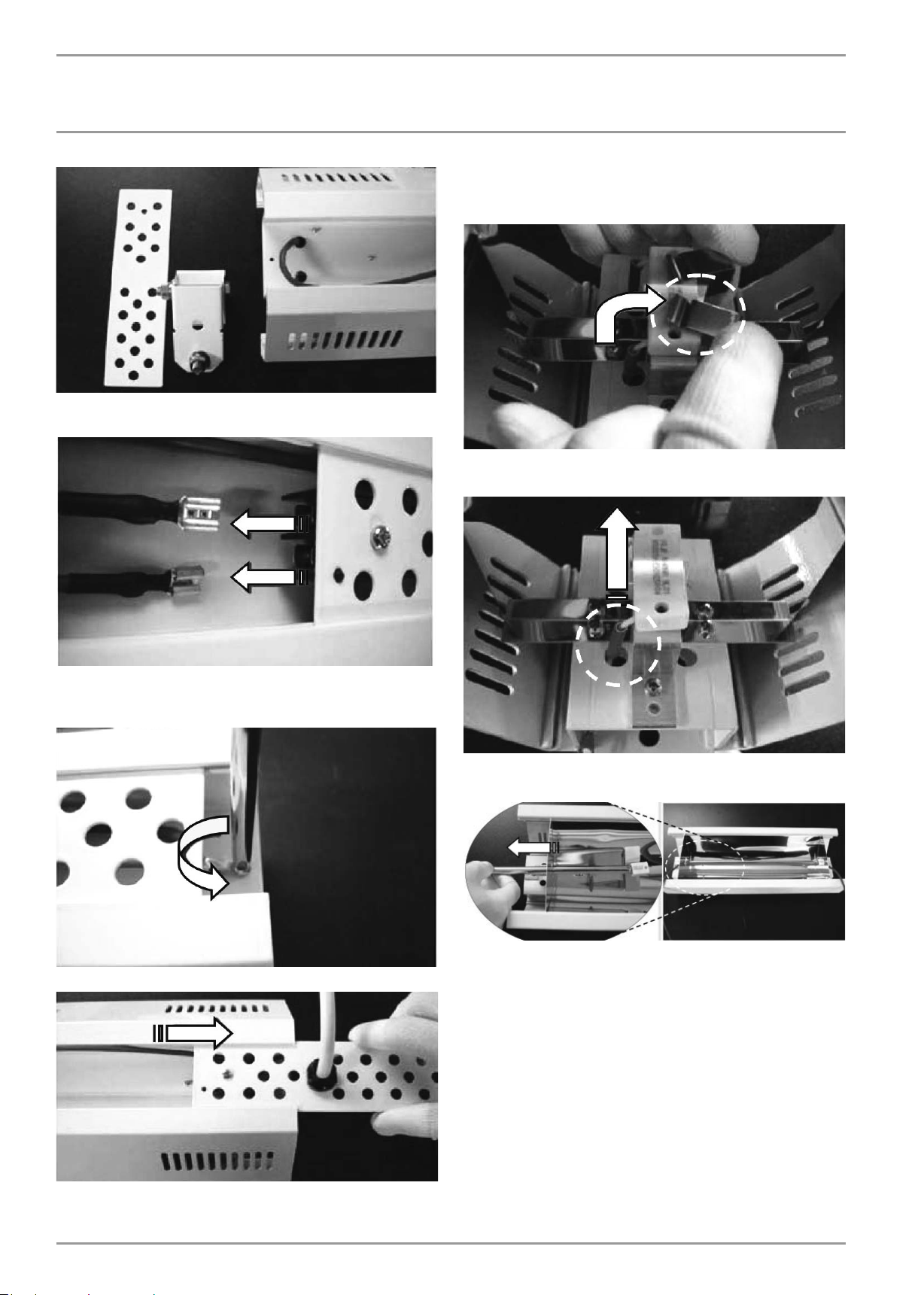
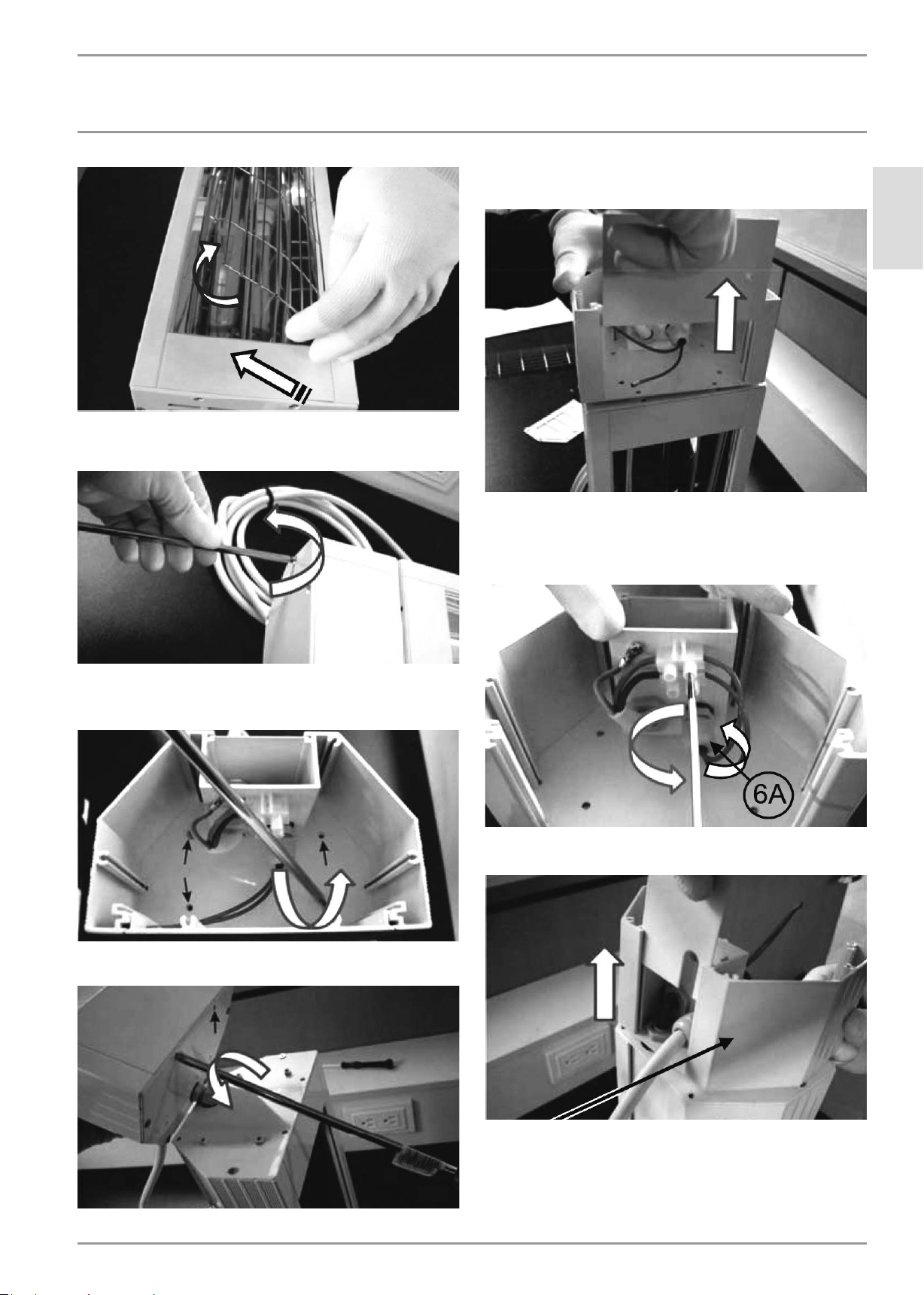
9.7.1 Heat lamp replacement - CIR 150-1 I
1 Compress the width of the protective grill to retract the
wire tabs from under one edge of the heater body.
» Rotate the loose edge of the grill up and away from heater body.
» Pull the grill away from heater and remove from other edge of
heater body - place safety grill in a secure storage area:
WWW.STIEBEL-ELTRON-USA.COM SUNWARMTH™ CIR INFRARED HEATER| 9
INSTALLATION
INSTALLATION
5 Disconnect electrical supply cord spade connectors from
terminals:
8 Turn heater face up. Each end of the lamp has a rectangular
retainer block. Remove the stainless steel clips that secure
the retainer blocks at each end of the lamp:
9 Pull the lamp wires up and out from the heater body at each
end of the lamp:
6 Disconnect ground wire (electrical supply cord) from the
heater body by removing the anchor screw from the eye of
the ground terminal:
7 Slide power cord retainer plate from heater body:
10 Slide the lamp out through the refl ector end plate. Properly
and safely dispose of lamp:
11 The heat lamp is fragile - handle with care! Wear gloves. Do
not touch lamp with bare fi ngers! Oils from your skin will
damage the lamp.
» Install the new replacement lamp
» Reassemble heater in reverse order of steps above.
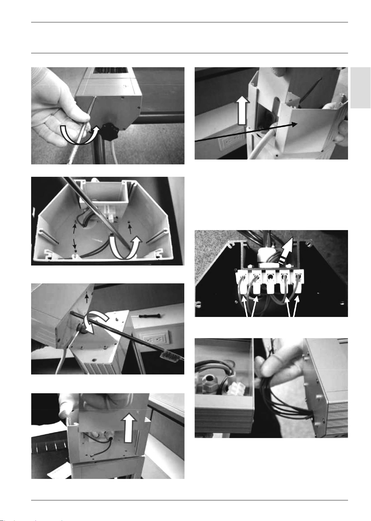
9.7.2 Heat lamp replacement - CIR 150-1 O and CIR 200-2 O
1 Compress the width of the protective grill to retract the wire
tabs from under one edge of the heater body.
» Rotate the lose edge of the grill up and away from
heater body.
» Pull the grill away from heater to remove from other edge
of heater body - place safety grill in a secure storage
container:
10 |SUNWARMTH™ CIR INFRARED HEATER WWW.STIEBEL-ELTRON-USA.COM
INSTALLATION
INSTALLATION
2 Remove connection box end cover. Six (6) Phillips screws
hold the end cover in place. Remove the screws and keep in a
secure storage area:
5 Disconnect electrical supply cord spade connectors from
terminals:
ENGLISH
6 Loosen 2 screws in terminal block that connect the red heat
lamp wires in place. Remove ends of red wires from terminal
block.
Loosen plastic collar on Liquid Tight Connector that secures
red wires to connection box:
3 Remove connection box end cover. Six (6) Phillips screws
hold the end cover in place. Remove the screws to secure
storage:
4 Remove 2 Phillips screws that fasten the connection box face
plate in place:
7 Slide power cord retainer plate from heater body (top surface
of heater):
8 Loosen plastic collar on second Liquid Tight Connector that
secures red wires through connection box end plate.
» Slide red wires out of connection box.
» Set connection box aside:
WWW.STIEBEL-ELTRON-USA.COM SUNWARMTH™ CIR INFRARED HEATER| 11
INSTALLATION
INSTALLATION
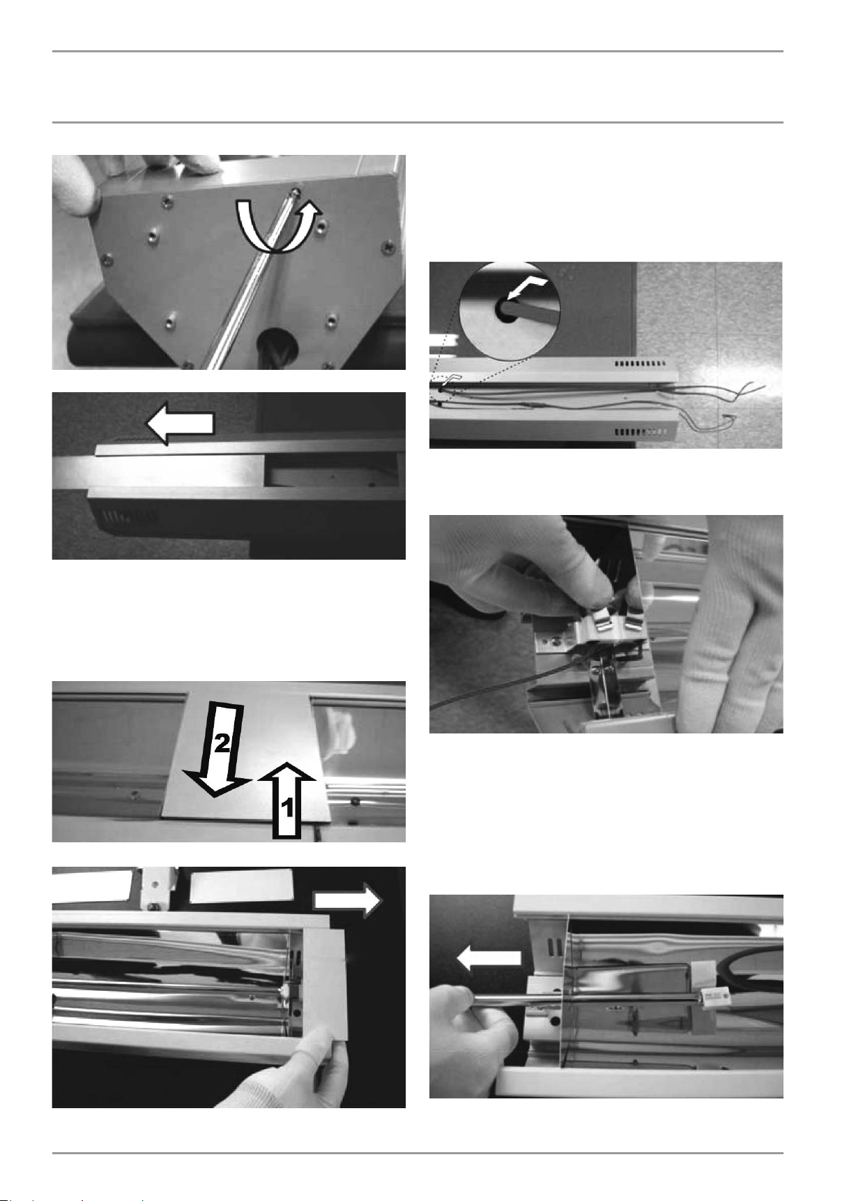
9 Remove end plate from heater: 6 Phillips screws fasten the
heater body end plate in place:
12 Remove the heat lamp retainer clip at each end of lamp:
13 The heat lamp is fragile! Carefully side old heat lamp out of
heater through rectangular slot in end of refl ector:
10 Slide cover plates and heater mounting bracket out from top
side of heater. Remove remaining end plate from other end
of heater:
11 Slide face plate out from each end of heater:
» Carefully install new heat lamp and clip in place.
» Reverse steps above to reassemble the heater.
9.7.3 Heat lamp replacement - CIR 400-2 O
1 Compress the width of the protective grill to retract the wire
tabs from under one edge of the heater body.
» Rotate the loose edge of the grill up and away from heater body.
» Pull the grill away from heater to remove from other edge of
heater body - place safety grill in a secure storage container.
» Repeat grill removal for other lamp if required:
2 Remove end plate from heater: 6 Phillips screws fasten the
heater body end plate in place:
12 |SUNWARMTH™ CIR INFRARED HEATER WWW.STIEBEL-ELTRON-USA.COM
INSTALLATION
INSTALLATION
3 Remove 4 Phillips screws that hold connection box to heater:
ENGLISH
7 Loosen screws in terminal block to remove wires as required:
» RED wires connect to Lamp #1 (closer to connection box)
» BLUE wires connect to Lamp #2 (further end from box)
» Do not disconnect power supply wires
» Loosen the threaded clamping collar on the Liquid Tight
Connector located behind the wiring terminal
4 Remove the 2 Phillips screws that fasten the electrical
connection box front face plate in place:
5 Slide the connection box front face plate out from the
electrical connection box:
» Pull wires out through the Liquid Tight Connector and top of
electrical connection box:
8 Slide lamp wires out of electrical connection box. Set
electrical connection box aside:
9 Remove interior end plate from heater: 6 Phillips screws
fasten the heater body end plate in place:
6 Slide power cord retainer plate from electrical connection
box (top surface):
WWW.STIEBEL-ELTRON-USA.COM SUNWARMTH™ CIR INFRARED HEATER| 13
INSTALLATION
INSTALLATION
10 Slide top cover plates out each end of top side of heater:
13 For this step, keep the heat lamp retainer clips in place at
each end of lamps. Heat lamp is fragile - use caution when
feeding wires through holes.
» Carefully feed each lamp wire from the top of the heater through
the hole in the heater body so that the wire is inside the heater
body (same as the lamp):
14 Remove the heat lamp retainer clips both ends of lamps.
» One clip at each end of heater
11 Remove the center face plate:
» The BOTTOM edge of the center Face Plate does not have a
lower lip
» Insert a fi ne edged slot screw driver between the heater body
and the BOTTOM edge of the face plate
» Pry the face plate from the heater body, and remove to storage:
12 Slide the end face plates out from each end of the heater:
» Two clips in the center of heater:
15 The heat lamp is very fragile - handle and assemble with
great care!
» Carefully slide old heat lamp out of heater through rectangular
slot in end of refl ector.
» Carefully install new heat lamp and clip in place.
» Reverse steps above to reassemble the heater.
» Take particular care not to damage the lamp at step 14 and
step 13:
14 |SUNWARMTH™ CIR INFRARED HEATER WWW.STIEBEL-ELTRON-USA.COM
INSTALLATION
APPLIANCE HANDOVER
10. Appliance handover
Explain the functions of the appliance to the user. Draw special
attention to the safety information. Hand the operating and
installation instructions to the user.
11. What to do if ...
... the appliance does not heat up:
» For 120 V models, ensure that the unit is plugged into a properly
grounded 120 V wall outlet and that the timer switch is on.
» For 240 V models, ensure that the timer switch is on and that
there is adequate power available at the circuit breaker and that
the breaker hasn’t tripped. Check for faulty breaker(s).
... you notice a smell:
» For a short time after initial installation or after a long period
of inactivity, the unit may produce a smell. This is normal and
will not last long once regular operation resumes.
If you cannot remedy the fault, contact your contractor. To facilitate
and speed up your enquiry, please provide the number on the type
plate (Nr. XXXX-XXXX-XXXX)
12. Specifi cation
12.1 Recommended mounting and coverage
specifi cations
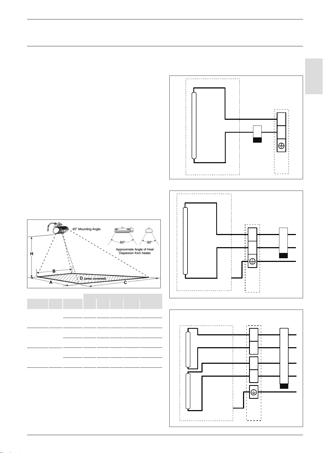
12.2 Wiring diagrams
CIR 150-1 I, CIR 150-1 O
Lamp
CIR 150-1 I/O
CIR 200-2 O
ENGLISH
N
L
K1
Off Delay Timer
SPST
Outllet
K1
Off Delay Timer
DPDT
Dim. of area heated
Model Power H A B C D E
CIR 150-1 I,
CIR 150-1 O
CIR 200-2 O 2000 W Min.: 8
CIR 400-2 O 4000 W Min.: 10
1500 W Min.: 7
(2.1 m)
Max.: 8
(2.4 m)
(2.4 m)
Max.: 9
(2.7 m)
(3.0 m)
Max.: 11 6
(3.5 m)
8 10
(2.7 m)
9 10
(3.0 m)
9 10
(3.0 m)
11 2
(3.4 m)
11 10
(3.6 m)
13 5
(4.1 m)
8 6
(2.6 m)
9 2
(2.8 m)
9 2
(2.8 m)
9 10
(3.0 m)
11 2
(3.4 m)
14 1
(4.3 m)
16 1
(4.9 m)
18 1
(5.5 m)
18 1
(5.5 m)
20
(6.1 m)
23
(7.0 m)
27 7
(8.4 m)
108 ft2
(10.1 m2)
133 ft2
(12.4 m2)
133 ft2
(12.4 m2)
165 ft2
(15.3 m2)
205 ft2
(19.0 m2)
275 ft2
(25.4 m2)
13.9 W / ft2
(148.5 W / m2)
11.3 W / ft2
(121.0 W / m2)
15.0 W / ft2
(161.3 W / m2)
12.1 W / ft2
(130.7 W / m2)
19.5 W / ft2
(210.5 W / m2)
14.5 W / ft2
(157.5 W / m2)
CIR 200-2 O
CIR 400-2 O
L2
Lamp
L1
Box
Junction
K1
Off Delay Timer
DPDT
L2
L1
Lamp 2Lamp 1
L2
L1
CIR 400-2 O
WWW.STIEBEL-ELTRON-USA.COM SUNWARMTH™ CIR INFRARED HEATER| 15
Junction
Box
INSTALLATION
SPECIFICATION
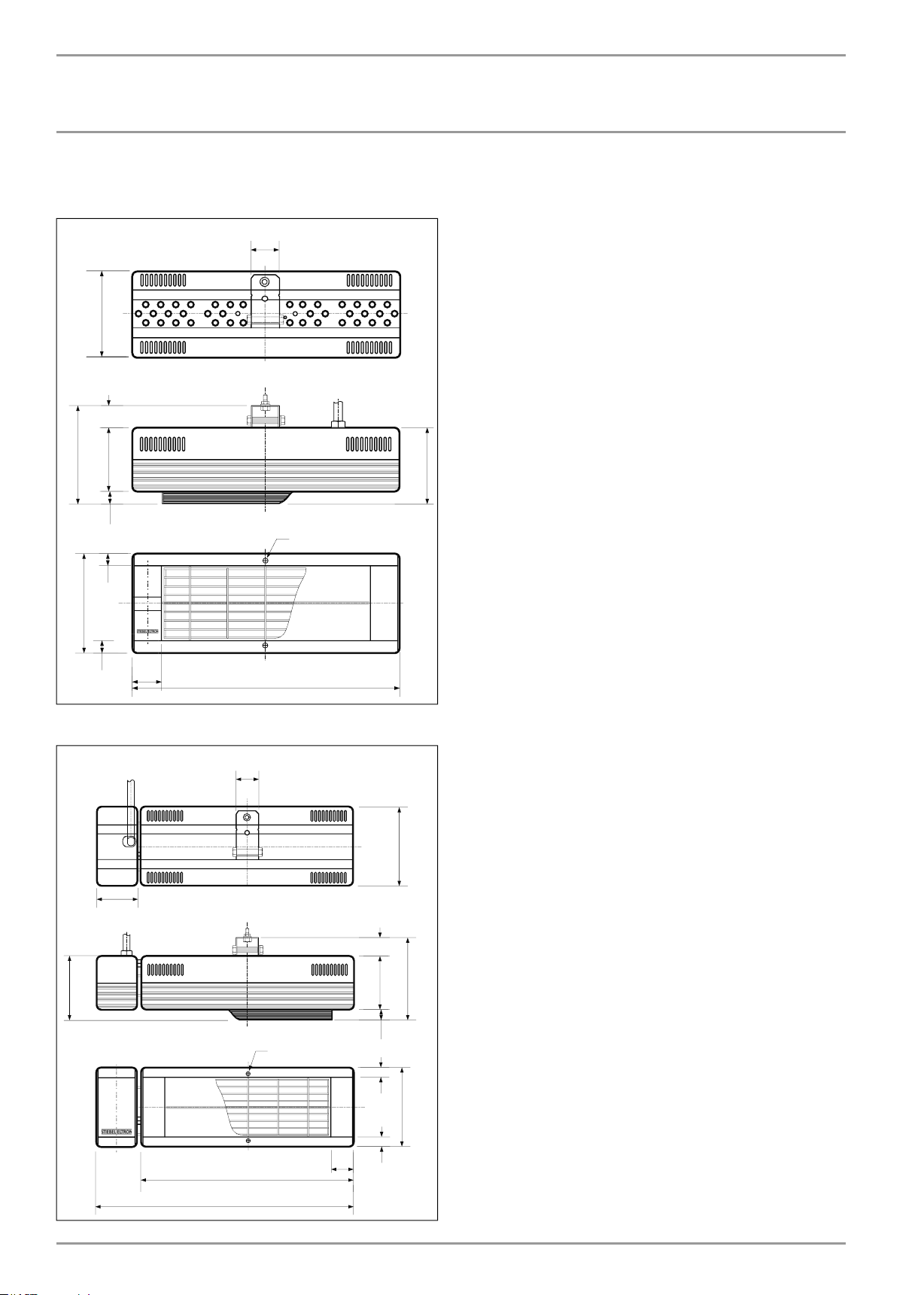
12.3 Dimensions
CIR 150-1 I
5 11/16Ý
(14.5 cm)
1 5/16Ý
(3.3 cm)
1 9/16Ý
(4 cm)
3 3/4Ý
(9.5 cm)
11/16Ý
(1.7 cm)
5/8Ý
(1.6 cm)
5 11/16Ý
(14.5 cm)
1 9/16Ý
(4 cm)
5/8Ý
(1.6 cm)
CIR 150-1 O & CIR 200-2 O
(39.5 cm)
1 9/16Ý
(4 cm)
15 9/16Ý
#10
5 11/16Ý
(14.5 cm)
4 7/16Ý
(11.2 cm)
3Ý
(7.6 cm)
1 5/16Ý
(3.3 cm)
3 3/4Ý
5 11/16Ý
(9.5 cm)
11/16Ý
(1.7 cm)
5/8Ý
(1.6 cm)
5/8Ý
(1.6 cm)
(14.5 cm)
5 11/16Ý
(14.5 cm)
4 1/4Ý
(10.8 cm)
15 9/16Ý
(39.5 cm)
18 9/16Ý
(47.1 cm)
#10
1 9/16Ý
(4 cm)
16 |SUNWARMTH™ CIR INFRARED HEATER WWW.STIEBEL-ELTRON-USA.COM
INSTALLATION
SPARE PARTS
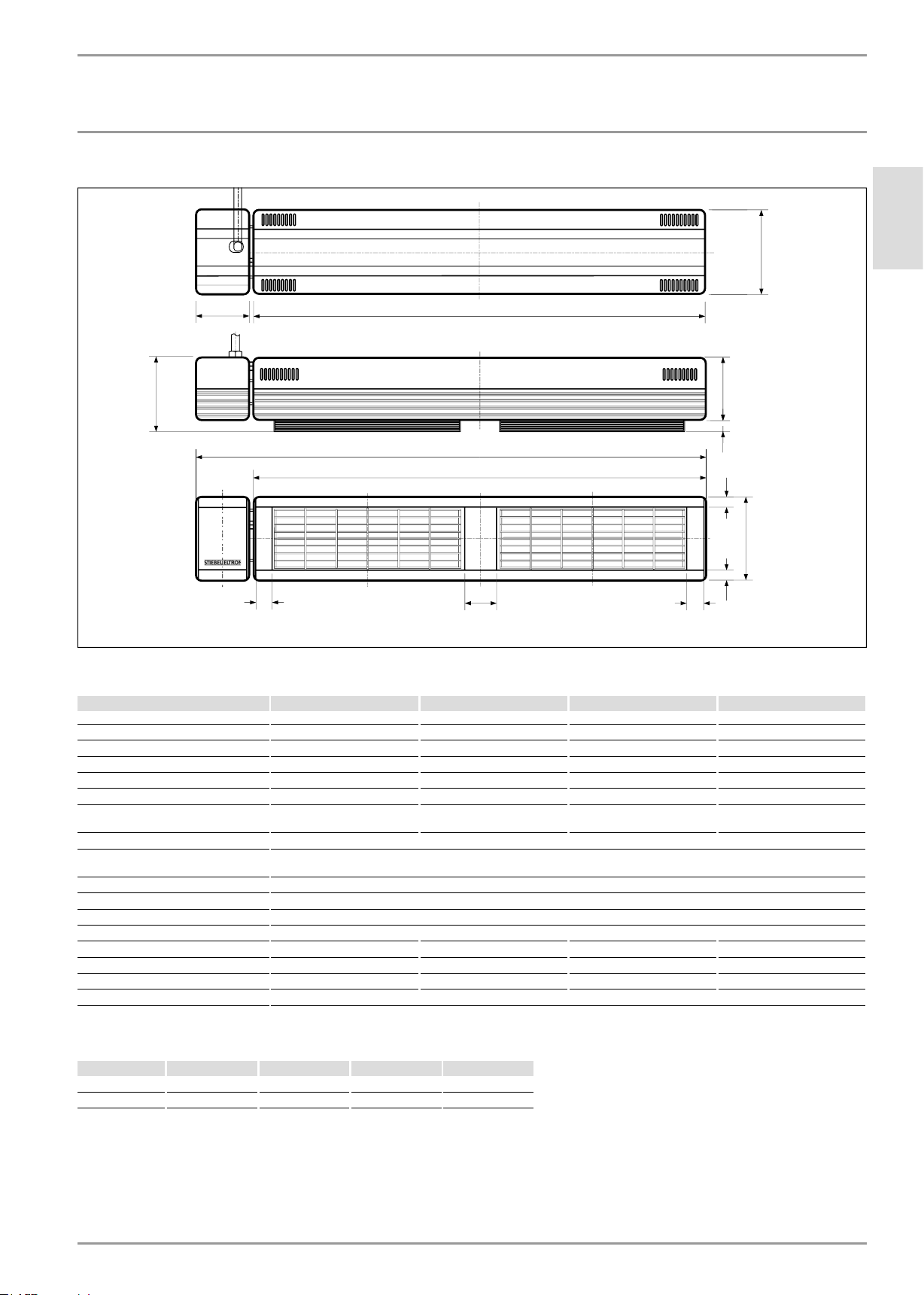
CIR 400-2 O
5 11/16Ý
(14.5 cm)
ENGLISH
4 7/16Ý
(11.2 cm)
Ý
(10 cm)
Ý
(4 cm)
Ý
(89.5 cm)
Ý
(79.5 cm)
Ý
(79.5 cm)
Ý
(8 cm)
Ý
(4 cm)
Ý
Ý
(1.6 cm)
Ý
(1.6 cm)
(9.5 cm)
Ý
(1.7 cm)
5 11/16Ý
(14.5 cm)
12.4 Specifi cation table
Model CIR 150-1 I CIR 150-1 O CIR 200-2 O CIR 400-2 O
Item No. 234047 234048 234049 234050
Usage indoor only indoor/outdoor indoor/outdoor indoor/outdoor
Testing standard ANSI/UL 1278 ANSI/UL 2021 ANSI/UL 2021 ANSI/UL 2021
Voltage, 60Hz 115–120 V 115–120 V 230–240 V 230–240 V
Wattage 1.5 kW 1.5 kW 2.0 kW 4.0 kW
Amperage 12.5 A 12.5 A 8.3 A 2 x 8.3 A
Required number and size of
circuit breakers
Required wire size (copper) 14 AWG
Lamp temperature 2420 °F, ±360 °F
Lamp life (normal conditions) 5000 hours
Lamp color temperature 1600 K, ±200 K
Height 5 11/16˝ / 145 mm
Width 15 9/16˝ / 395 mm 18 9/16˝ / 471 mm 18 9/16˝ / 471 mm 38 ½˝ / 978 mm
Depth 4 7/16˝ / 112 mm 4 ¼˝ / 108 mm 4 ¼˝ / 108 mm 4 7/16˝ / 112 mm
Weight 4.85 lb / 2.2 kg 5.5 lb / 2.5 kg 5.5 lb / 2.5 kg 8.8 lb / 4.0 kg
IP-Rating IP20 IP24 IP24 IP24
Color alpine white
20 A 20 A 15 A 2 x 15 A
1325 °C, ±200 °C
13. Spare Parts
Model CIR 150-1 I CIR 150-1 O CIR 200-2 O CIR 400-2 O
Protective Grill BHSG BHSG BHSG BHSG
Heat Lamp LGHS1520 LGHS1524 LGHS2024 (2) LGHS2024
WWW.STIEBEL-ELTRON-USA.COM SUNWARMTH™ CIR INFRARED HEATER| 17
 Loading...