

STIEBEL ELTRON WPL E, WPL cool Series, WPL 13 E, WPL 13 cool, 227756 Series Manual
...
CONTENTS
SPECIAL INFORMATION
OPERATION
1. General information �����������������������������������������3
1.1 Relevant documents_____________________________________________ 3
1.2 Safety instructions _______________________________________________ 3
1.3 Other symbols in this documentation _______________________ 4
1.4 Units of measurement __________________________________________ 4
1.5 Standardised output data ______________________________________ 4
2. Safety ���������������������������������������������������������� 4
2.1 Intended use ______________________________________________________ 4
2.2 Safety instructions _______________________________________________ 4
2.3 Test symbols ______________________________________________________ 4
3. Appliance description ���������������������������������������5
3.1 Function ___________________________________________________________ 5
4. Settings �������������������������������������������������������5
5. Maintenance and care ���������������������������������������5
6. Troubleshooting ����������������������������������������������6
INSTALLATION
7. Safety ���������������������������������������������������������� 7
7.1 General safety instructions ____________________________________ 7
7.2 Instructions, standards and regulations ____________________ 7
7.3 Operation of the appliance in buildings with
combustion equipment _________________________________________ 7
8. Appliance description ���������������������������������������7
8.1 Standard delivery ________________________________________________ 7
8.2 Required accessories ___________________________________________ 7
8.3 Additional accessories __________________________________________ 7
9. Preparations �������������������������������������������������� 8
9.1 Sound emissions _________________________________________________ 8
9.2 Minimum clearances ____________________________________________ 8
9.3 Preparation of the installation site ___________________________ 9
9.4 Electrical installation___________________________________________ 10
9.5 Buffer cylinder __________________________________________________ 11
10. Installation �������������������������������������������������� 11
10.1 Transport _________________________________________________________ 11
10.2 Siting and connecting the appliance ________________________ 11
10.3 Heating water connection _____________________________________ 13
10.4 Second heat source_____________________________________________ 13
10.5 Filling the heating system ____________________________________ 14
10.6 Minimum flow rate _____________________________________________ 14
10.7 Condensate drain _______________________________________________ 15
10.8 Checking the draining of condensate _______________________ 16
10.9 High limit safety cut-out for underfloor heating
systems ___________________________________________________________ 16
11. Power supply ����������������������������������������������� 16
11.1 Control panel ____________________________________________________ 16
12. Fitting casing components �������������������������������� 18
12.1 Outdoor installation ____________________________________________ 18
12.2 Indoor installation ______________________________________________ 19
13. Commissioning ��������������������������������������������� 21
13.1 Check before commissioning the heat pump manager _21
13.2 Commissioning the heat pump manager __________________ 22
13.3 Initial start-up ___________________________________________________ 22
13.4 Settings ___________________________________________________________ 23
14. Appliance shutdown ��������������������������������������� 23
14.1 Standby mode ___________________________________________________ 23
14.2 Power interruption _____________________________________________ 23
15. Appliance handover ���������������������������������������� 24
16. Troubleshooting �������������������������������������������� 24
16.1 Controls on the IWS ____________________________________________ 24
16.2 Resetting the high limit safety cut-out _____________________ 24
16.3 Fan noise _________________________________________________________ 25
17. Maintenance ������������������������������������������������ 25
17.1 Clean condensate pan and drain ____________________________25
18. Specification ������������������������������������������������ 26
18.1 Dimensions and connections ________________________________ 26
18.2 Wiring diagram _________________________________________________ 28
18.3 Output diagrams ________________________________________________ 30
18.4 Data table ________________________________________________________ 36
GUARANTEE
ENVIRONMENT AND RECYCLING
2 | WPL E | WPL cool www.stiebel-eltron.com
SPECIAL INFORMATION
General information
SPECIAL INFORMATION
- The appliance may be used by children aged8
and older and persons with reduced physical,
sensory or mental capabilities or a lack of experience and know-how, provided that they are
supervised or they have been instructed on how
to use the appliance safely and have understood
the potential risks. Children must never play with
the appliance. Children must never clean the appliance or perform user maintenance unless they
are supervised.
- The connection to the power supply must be in
the form of a permanent connection. Ensure the
appliance can be separated from the power supply by an isolator that disconnects all poles with
at least 3mm contact separation.
- Maintain the minimum clearances to ensure trouble-free operation of the appliance and facilitate
maintenance work.
OPERATION
1. General information
The chapters "Special information" and "Operation" are intended
for both users and qualified contractors.
The chapter "Installation" is intended for qualified contractors.
Note
Read these instructions carefully before using the appliance and retain them for future reference.
Pass on the instructions to a new user if required.
1.1 Relevant documents
Operating and installation instructions for the WPM heat
pump manager
Operating and installation instructions for system
components
1.2 Safety instructions
1.2.1 Structure of safety instructions
- Maintenance work, such as checking the electrical safety, must only be carried out by a qualified
contractor.
- We recommend an annual inspection (to establish
the current condition of the system), and maintenance by a qualified contractor if required (to
return the system to its original condition).
- Never interrupt the power supply, even outside
the heating season. The system's active frost protection is not guaranteed if the power supply is
interrupted.
- The heat pump manager automatically switches
the heat pump to summer or winter mode.
- If the heat pump is completely switched off and
there is a risk of frost, drain the system on the
water side.
KEYWORD Type of risk
!
Here, possible consequences are listed that may result
from failure to observe the safety instructions.
Steps to prevent the risk are listed.
1.2.2 Symbols, type of risk
Symbol Type of risk
!
1.2.3 Keywords
KEYWORD Meaning
DANGER Failure to observe this information will result in serious
WARNING Failure to observe this information may result in serious
CAUTION Failure to observe this information may result in non-seri-
Injury
Electrocution
injury or death.
injury or death.
ous or minor injury.
www.stiebel-eltron.com WPL E | WPL cool | 3
OPERATION
Safety
1.3 Other symbols in this documentation
Note
General information is identified by the adjacent symbol.
Read these texts carefully.
Symbol Meaning
!
0
Material losses
(appliance damage, consequential losses and environmental pollution)
Appliance disposal
:a
This symbol indicates that you have to do something. The ac-
tion you need to take is described step by step.
1.4 Units of measurement
Note
All measurements are given in mm unless stated otherwise.
1.5 Standardised output data
Information on determining and interpreting the specified standardised output data.
1.5.1 Standard: EN 14511
The output data specifically mentioned in text, diagrams and
technical datasheets has been calculated according to the test
conditions of the standard shown in the heading of this section.
Generally, these standardised test conditions will not fully meet
the conditions found at the installation site of the system user.
Depending on the chosen test method and the extent to which
this method deviates from the conditions defined in the norm
shown in the heading of this section, any deviations can have a
considerable impact.
Additional factors that have an influence on the test values are the
measuring equipment, the system configuration, the age of the
system and the flow rates.
A confirmation of the specified output data can only be obtained
if the test conducted for this purpose is also performed in accordance with the conditions defined in the norm shown in the
heading of this section.
2. Safety
2.1 Intended use
The WPLE appliance is designed for central heating within the
application limits given in the specification.
The WPLcool appliance is designed for central heating and cooling
within the application limits given in the specification.
The appliance is intended for domestic use. It can be used safely
by untrained persons. The appliance can also be used in non-domestic environments, e.g. in small businesses, as long as it is
used in the same way.
Any other use beyond that described shall be deemed inappropriate. Observation of this document is also part of the correct
use of the unit.
2.2 Safety instructions
Observe the following safety instructions and regulations.
- Only qualified contractors are permitted to carry out electrical work and the installation of the heating circuit.
- The qualified contractor is responsible for adherence
to all applicable regulations during installation and
commissioning.
- The appliance should only be operated once it is fully installed and all safety equipment has been fitted.
- Protect the appliance from dust and dirt during building
work.
WARNING Injury
!
The appliance may be used by children over 8years of
age and persons with reduced physical, sensory or mental capabilities or a lack of experience and expertise,
provided that they are supervised or they have been
instructed on how to use the appliance safely and have
understood the potential risks. Children must never play
with the appliance. Children must never clean the appliance or perform user maintenance unless they are
supervised.
WARNING Injury
!
For safety reasons, only operate the appliance with
the casing closed.
2.3 Test symbols
See type plate on the appliance.
4 | WPL E | WPL cool www.stiebel-eltron.com
OPERATION
Appliance description
3. Appliance description
The appliance is an air | water heat pump that operates as a heating heat pump. The appliance extracts heat
from the outdoor air at a low temperature level and transfers it to the heating water at a higher temperature level.
The heating water can be heated up to a flow temperature of 60 °C.
With the appropriate accessories, this appliance may be installed
internally or externally.
The appliance is equipped with an electric emergency/booster
heater (DHC). If the dual mode point is undershot in mono mode
operation, the electric emergency/booster heater is activated to
safeguard heating operation and the provision of high DHW temperatures. In such a case in mono energetic operation, the electric
emergency/booster heater is activated as a booster heater.
Additional features
- Suitable for underfloor and radiator heating systems
- Preferred for low temperature heating systems
- Still extracts heat from the outdoor air at – 20°C outside
temperature
- Corrosion-protected, external casing made from hot-dipped
galvanised sheet steel plus stove-enamelled finish
- Comprises all components and safety equipment required for
operation
- Filled with non-combustible safety refrigerant
3.1.2 Cooling (WPLcool only)
Material losses
!
The heat pump is not suitable for continuous, year-round
0
cooling.
Observe the application limits (see chapter "Specifi-
cation/ Data table").
Rooms are cooled by reversing the heat pump circuit. Heat is
extracted from the heating water and the evaporator transfers
this heat to the outdoor air.
Area cooling requires the installation of the FEK remote control
unit in a reference room to capture the relative humidity and the
room temperature as part of dew point monitoring.
Heat pump application limit
The heat pump is switched off if the outside temperature falls
below the selected lower application limit for cooling (LIMITCOOLING parameter).
4. Settings
The appliance is controlled with the heat pump manager and requires no special operation.
Please observe the heat pump manager operating and instal-
lation instructions.
Note
To control the heating system, you will need the WPM
heat pump manager.
=
[]]
:_______
3.1 Function
3.1.1 Heating
Heat is extracted from the outdoor air via the heat exchanger
(evaporator) on the air side. The refrigerant evaporates and is
compressed by a compressor. This process requires electrical
energy.
The refrigerant is then at a higher temperature level and transfers
the heat drawn from the air to the heating system via an additional
heat exchanger (condenser). The refrigerant then expands and the
cycle begins again.
At air temperatures below approx. 7°C, the humidity in the air
condenses as hoarfrost on the evaporator fins. This hoarfrost is
automatically defrosted. Water created by this defrosting process
collects in the defrost pan and is drained off via a hose.
During the defrost cycle, the fan is switched off and the heat pump
circuit is reversed. The heat required for defrosting is drawn from
the buffer cylinder. The heat pump automatically reverts to heating
mode at the end of the defrost cycle.
5. Maintenance and care
Material losses
!
Maintenance work, such as checking the electrical safety,
0
[]]
A damp cloth is sufficient for cleaning all plastic and sheet metal
parts. Never use abrasive or corrosive cleaning agents.
Protect the appliance from dust and dirt during building
Every month, check that the condensate drain is working
We recommend a regular inspection (to establish the current condition of the system), and maintenance by a qualified contractor if
required (to return the system to its original condition).
~~~~
must only be carried out by a qualified contractor.
Note
Keep the air discharge and intake apertures free
from snow and leaves.
work.
correctly (visual inspection). When doing so, check for water
collecting below or next to the appliance. For further information, see chapter "Troubleshooting".
Material losses
!
In dual mode operation, return water from the second
0
heat generator may flow through the heat pump. Please
note that the return temperature must be no higher than
60 °C.
www.stiebel-eltron.com WPL E | WPL cool | 5

OPERATION
Troubleshooting
6. Troubleshooting
Fault Cause Remedy
There is no hot
water or the
heating system
remains cold.
Water is leaking
from the appliance.
Indoor installation: Condensate
is collecting on
the outside of the
appliance or on
the air hoses.
Outdoor installation: Condensate
is collecting on
the outside of the
appliance.
No power at the appliance.
The condensate drain
may be blocked.
The drying out phase of
the building is not yet
complete.
The relative humidity in
the air is high (≥60%).
The appliance is sited
in a damp room. Damp
rooms are those where
humidity in the air is
high. They may, for example, be used for drying
laundry.
The air hoses are incorrectly fitted or poorly
sealed.
Cold air is escaping.
The heat pump is extracting heat from the outdoor
air to heat the building.
This can cause the humidity in the outdoor air
to accumulate as dew or
frost on the cooled heat
pump casing. This is not
a defect.
Check the fuses/MCBs in your
distribution board. Replace the
fuses/reset the MCBs if required.
Notify your qualified contractor if
the fuses/MCBs blow/trip again.
Call your contractor to have the
condensate drain cleaned out.
This condensate should no
longer form on the appliance
after the house is approx.two
years old, providing the room is
sufficiently well ventilated and
dehumidified.
A change in weather conditions
should no longer cause condensation to form on the appliance.
Ensure that the room is adequately ventilated and dehumidified. If necessary, hang your
laundry in a different room.
Use a vented tumble dryer.
Please note that condenser tumble dryers do not reduce the level
of humidity in the air.
Check that the air hoses are
correctly fitted and sealed. If
necessary, contact your qualified
contractor.
Note
Even when the condensate is draining away correctly,
expect water to drip from the appliance onto the floor.
If you cannot remedy the fault, notify your qualified contractor.
To facilitate and speed up your enquiry, please provide the serial
number from the type plate (000000-0000-000000).
Sample type plate
Montageanweisung beachten! Dichtheit geprüft!
Made in Germany
*xxxxxxxxxxxxxxxxxx*
1(
-
1
1 Number on the type plate
26_03_01_1736
6 | WPL E | WPL cool www.stiebel-eltron.com
INSTALL ATION
Safety
INSTALLATION
7. Safety
Only a qualified contractor should carry out installation, commissioning, maintenance and repair of the appliance.
7.1 General safety instructions
We guarantee trouble-free function and operational reliability only
if original accessories and spare parts intended for the appliance
are used.
8.1.2 Casing components – outdoor installation
- Hood – outdoor installation
- Front panel
- Back panel
- Pipe bend for heating circuit flow
- Pipe bend for heating circuit return
8.1.3 Casing components for indoor installation
- Cover - indoor installation
- Front panel
- Back panel
- Pipe bend for heating circuit return
7.2 Instructions, standards and regulations
Note
Observe all applicable national and regional regulations
and instructions.
7.3 Operation of the appliance in buildings with
combustion equipment
As the appliance can produce negative pressure in the installation
room, we recommend using a tightly sealing door between the
installation room and the living space for operation with combustion equipment.
If, due to its use, the installation room is connected to the extract air system, you must also allow for a supply air valve in the
installation room in this particular case to prevent any further
increase in the negative pressure in the installation room. The
negative pressure created by the appliance in the installation room
is heavily influenced by the pressure drop in the outdoor air line.
For this reason, the outdoor air line in particular should be as
short as possible.
8. Appliance description
For outdoor installation the appliance offers additional frost protection of the heating water pipes. The integral frost protection
circuit starts the heating circulation pump in the heat pump circuit
automatically at +8°C condenser temperature, and in doing so
ensures circulation in all water-filled sections.
The heat pump starts automatically when the temperature in the
heat pump circuit drops below +5°C.
8.1 Standard delivery
The casing components for the appliance are delivered in a separate packing unit.
8.1.1 Standard appliance
- Type plate
8.2 Required accessories
8.2.1 Outdoor installation
- WPM3 heat pump manager
- Accessories – outdoor installation
- Pressure hoses SD25 or SD32
8.2.2 Indoor installation
- WPM3 heat pump manager
- Accessories – indoor installation
- Pressure hoses SD25 or SD32
8.2.3 Cooling
- Remote control for heating systems FEK
8.3 Additional accessories
8.3.1 Outdoor installation
- Remote control for FE7 heating systems
- Water softening fitting HZEA
- SP cool distributor strip
- Internet Service Gateway ISG
8.3.2 Indoor installation
- Air hose DN 560 x 4 m
- Hose connection panel 560
- Wall outlet AWG 560 H-SR
- Wall outlet AWG 560 H-GL
- Wall outlet AWG 560 V-SR
- Wall outlet AWG 560 V-GL
- Wall outlet AWG 560 L
- Wall outlet AWG 600 L
- Remote control for FE7 heating systems
- Condensate pump PK 10
- Water softening fitting HZEA
- SP cool distributor strip
- Internet Service Gateway ISG
www.stiebel-eltron.com WPL E | WPL cool | 7
INSTALL ATION
Preparations
9. Preparations
9.1 Sound emissions
The appliance is louder on the air intake and air discharge sides
than on the two enclosed sides. Take the following information
into account when selecting the installation location.
Note
For details regarding the sound power level, see chapter
"Specification / Data table".
9.1.1 Sound emissions for outdoor installation
- Lawn areas and shrubs help reduce the spread of noise.
- Noise propagation can also be reduced through dense palisades or similar.
Ensure that the entire appliance frame is in full contact
with the substrate. Uneven substrates can increase sound
emissions.
Ensure that the air intake direction is the same as the dom-
inant wind direction. Air should not be drawn in against the
wind.
Ensure that the air intake and air discharge are never direct-
ed towards noise-sensitive rooms of the house, e.g. bedrooms, or neighbouring houses.
Avoid installation on large, echoing floor areas, e.g. tiled
floors.
Avoid installation between reflective building walls. Reflect-
ing building walls can increase the noise level.
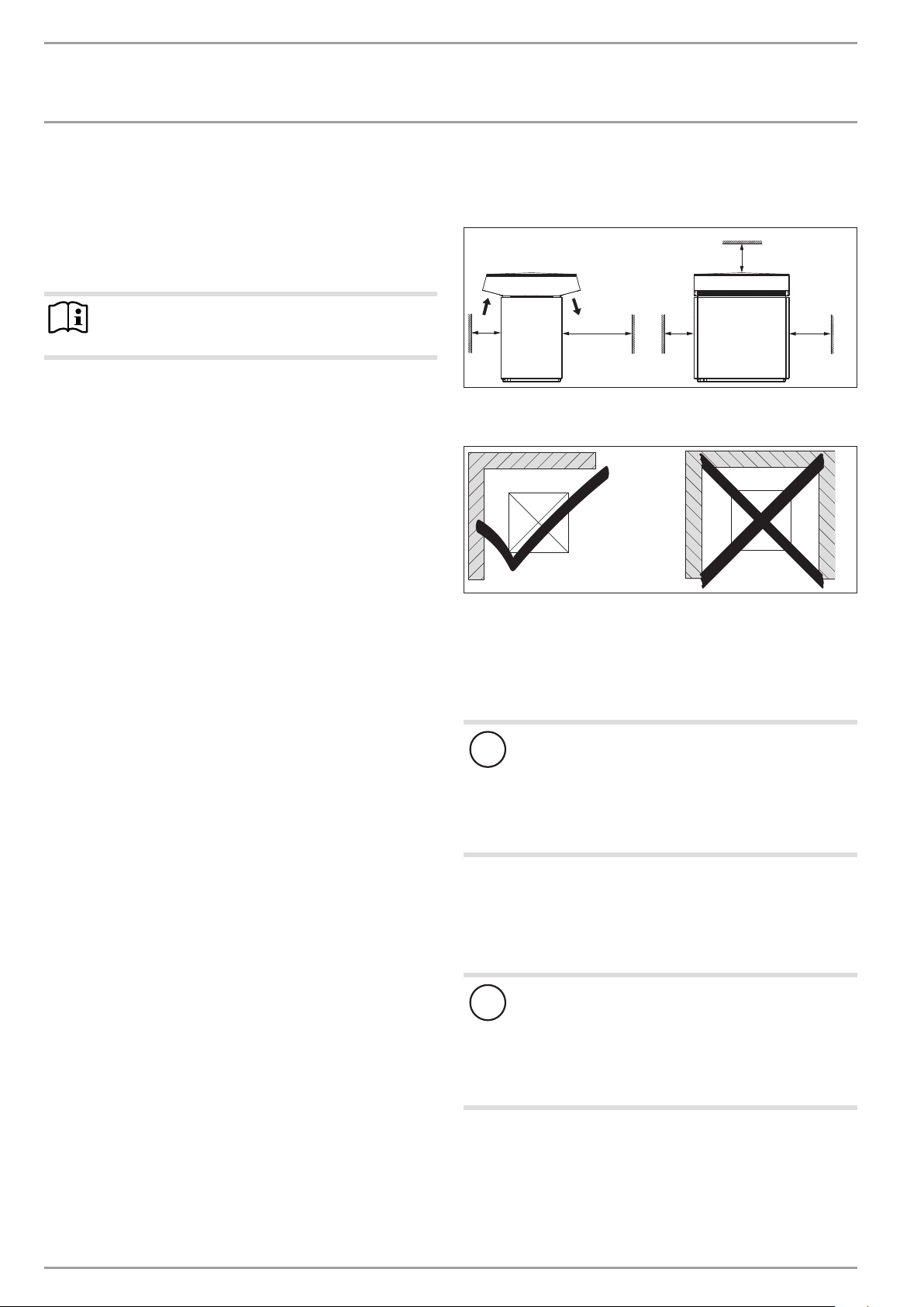
9.2 Minimum clearances
9.2.1 Outdoor installation
≥700
\
≥500
Maintain the minimum clearances to ensure trouble-free op-
eration of the appliance and facilitate maintenance work.
Never install the appliance in a recess. Two sides of the ap-
pliance must remain exposed.
In order to prevent air "short circuits", maintain the minimum
clearances in the case of surrounding structures and in particular in the case of cascades. Maintain the flow rate on the
heat source side (see chapter "Specification / data table").
≥2000
≥500
≥1000
D0000019241
91_00_00_0036
9.1.2 Sound emissions for indoor installation
- Never install on joists.
Ensure that the entire appliance frame is in full contact
with the substrate. Uneven substrates can increase sound
emissions.
Never install the appliance directly below or next to a living
room or bedroom.
Never direct the air intake and discharge apertures in exter-
nal walls towards neighbouring windows or living rooms/
bedrooms.
Protect pipe outlets through walls and ceilings with anti-vi-
bration insulation.
Material losses
!
Please note that both the flow of outdoor air into the
0
appliance, and the flow of exhaust air from the appliance
must be unimpeded.
If the air intake and discharge of the appliance are obstructed by surrounding objects, this may cause a thermal
short-circuit.
Ensure that the appliance is not fully enclosed by objects
such as buildings, walls or fences.
If the air discharge side of the appliance faces the wall of a house,
the cool air from the air discharge may cause condensate to form
on this wall.
Material losses
!
The air flow rate through the appliance must not fall
0
below the minimum level. If the air flow rate falls below
the minimum level, trouble-free operation of the appliance is not guaranteed.
Ensure that the minimum air flow rate is maintained
(see chapter “Specification/ Data table”).
8 | WPL E | WPL cool www.stiebel-eltron.com
INSTALL ATION
1
6
Preparations
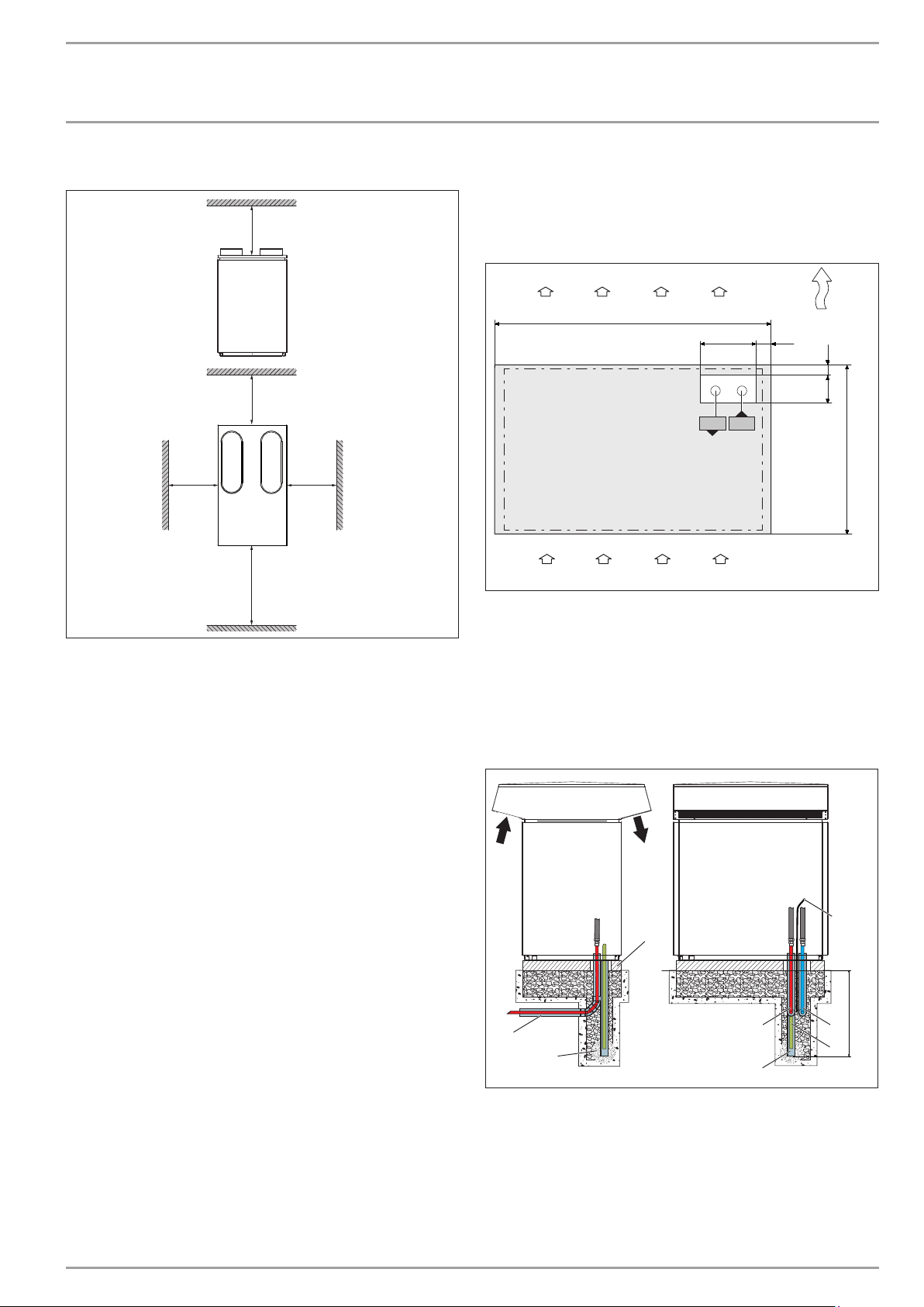
9.2.2 Indoor installation
≥500
1//////////f'///////P
≥300
≥500
0 0
I
≥1000
Maintain the minimum clearances to ensure trouble-free op-
eration of the appliance and facilitate maintenance work.
≥500
I
9.3 Preparation of the installation site
9.3.1 Outdoor installation
Provide a recess (space) in the base to enable supply pipes/
cables to be routed into the appliance from below.
Foundations with recess
1240
260 70
r-----
4
L_f~i
d01d02
...,.
____
-
0 0 0 0
2
1 Air discharge
2 Air intake
D0000019242
3 Main wind direction
4 Recess
d01 Heat pump flow
d02 Heat pump return
Ensure that the foundations offer an adequate recess.
I
_J
3
50
130
800
D0000056558
General information
See chapter "Sound emissions".
Ensure that the appliance is accessible from all sides.
Ensure that the substrate is level, even, solid and permanent.
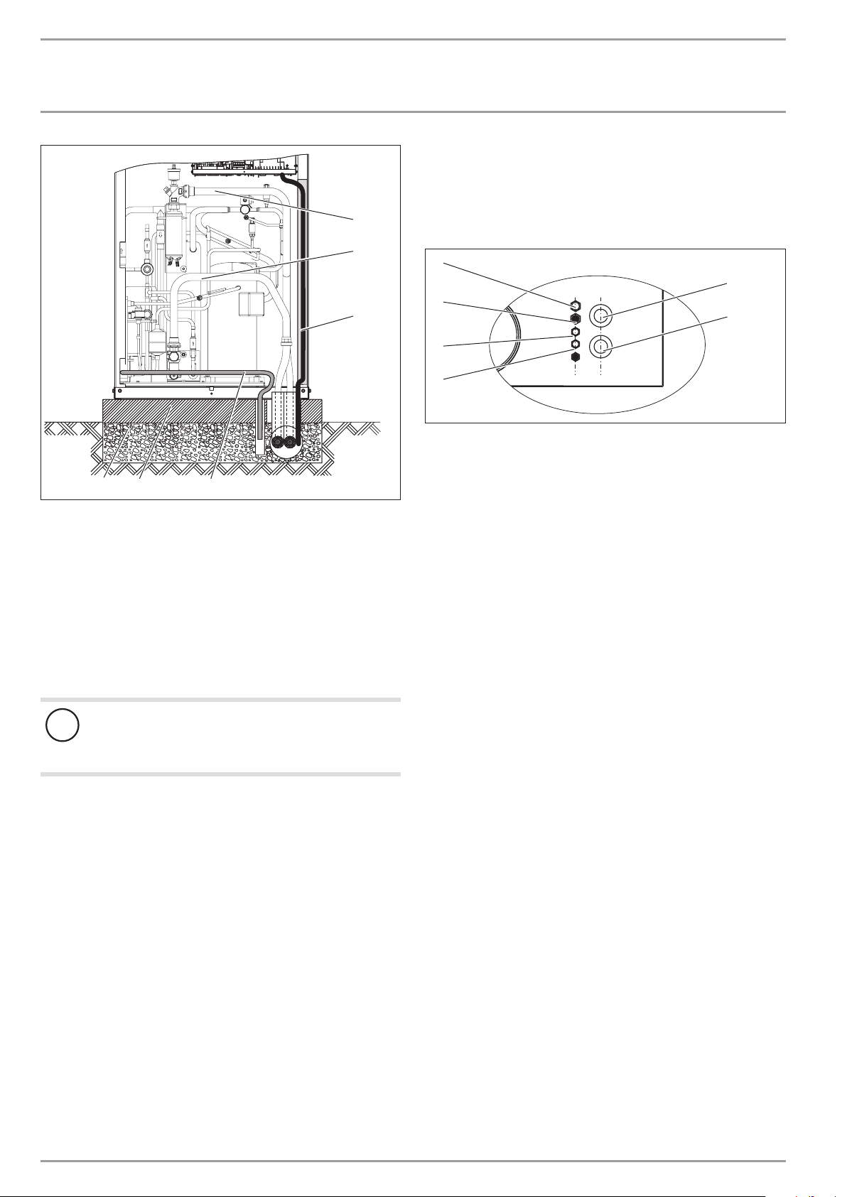
Example: Routing pipes in the base
4
3
5
A Depth of frost line
1 Heating circuit flow
2 Heating circuit return
3 Conduit for supply lines/cables
4 Foundation
5 Gravel bed
6 Drainage pipe
7 Condensate drain hose
8 Electrical cables/leads
8
A
1 2
7
D0000019237
www.stiebel-eltron.com WPL E | WPL cool | 9
INSTALL ATION
Preparations
Observe the following information:
- Also protect all supply lines/cables against humidity, damage
and UV radiation by means of a conduit.
- Allow the conduits for the supply lines to protrude slightly
above the foundations. Ensure that no water can enter the
conduits.
- To facilitate connection to the appliance, we recommend
using flexible supply pipes/cables in the case of outdoor
installation.
- Only use weather-resistant cables.
- Protect the heating circuit flow and return lines against frost
with sufficient thermal insulation. Provide thermal insulation
in accordance with applicable regulations.
Note
When routing the condensate drain hose, observe chapter
"Installation / Condensate drain".
9.3.2 Indoor installation
Material losses
!
The installation room floor must be water resistant. Dur-
0
ing appliance operation, the outdoor air releases up to
50l of condensate per day. If humidity levels in the installation room are high, condensate may form on the
appliance and air hoses. If the condensate drain is not
installed correctly or if maintenance is not carried out
properly, water may escape. We recommend installing a
drain in the installation room floor.
The room where the appliance is installed must meet the following
conditions:
- free from the risk of frost
- The room must not be subject to a risk of explosions arising
from dust, gases or vapours.
- If installing the appliance in a plant room together with other
heating equipment, ensure that the operation of other heating equipment will not be compromised.
- Minimum volume of the installation room. The minimum
volume of the installation room is assured if the minimum
clearances are observed.
- Load bearing floor (for the weight of the appliance, see chapter "Specification/ Data table").
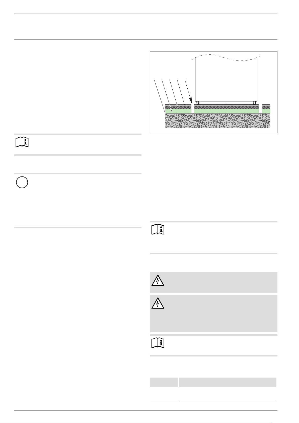
For installation on floating screeds, make provisions for quiet
heat pump operation.
-----
/
1 2 3 54
1 Concrete base
2 Impact sound insulation
3 Floating screed
4 Floor covering
5 Recess
Isolate the installation surface around the heat pump by
means of a recess. After completing the installation, seal the
recess with a water-impervious and sound insulating material, such as silicone for example.
Observe the following information:
- Connect the heating circuit flow and return lines via flexible
pressure hoses. Suitable pressure hoses are listed in chapter "Appliance description / Required accessories for indoor
installation".
Note
For details of the dimensions and positions of the air
intake and discharge apertures, as well as the outlets for
hydraulic lines and power cables, see chapter "Specification / Dimensions and connections / indoor installation".
9.4 Electrical installation
WARNING Electrocution
Carry out all electrical connection and installation work
&
in accordance with national and regional regulations.
-_-_-_-_-_-_-_-_-_-_-_-_-_-_-_-_-_-_-_-_-_-_-_-_-_-_-_-_----:::::::
WARNING Electrocution
Only use a permanent connection to the power supply.
&
Ensure the appliance can be separated from the power
supply by an isolator that disconnects all poles with at
least 3mm contact separation. This requirement can be
met with contactors, circuit breakers, fuses/MCBs, etc.
-----
26_03_01_1466
Note
The specified voltage must match the mains voltage.
Observe the type plate.
For wiring, use cable with the relevant cross-sections. Ob-
serve the applicable national and regional regulations.
MCB/fuse
rating
16 A
-
10 | WPL E | WPL cool www.stiebel-eltron.com
Conductor cross-section
2.5 mm²
1.5 mm² for only two live wires and routing on a wall or in
an electrical conduit on a wall.
INSTALL ATION
Installation
The electrical data can be found in the chapter "Specification". The
bus requires a J-Y (St) 2x2x0.8mm² cable.
====----
Material losses
!
Provide separate fuses/MCBs for the three power circuits,
i.e. those of the appliance, the control unit and the electricemergency/booster heater.
0
::::::::::C---=~==::;;::::::====:::::::::=---=--~
Material losses
!
Provide common fuses/MCBs for the control cable of the
appliance and the heat pump manager.
o
9.5 Buffer cylinder
The installation of a buffer cylinder is essential to ensure trouble-free operation of the appliance.
The buffer cylinder provides hydraulic separation of the volume
flows in the heat pump circuit and heating circuit, and also serves
as an energy source for defrosting.
0
====----
Material losses
!
A buffer cylinder with diffusion-proof insulation is essential for cooling mode.
--====
10.2 Siting and connecting the appliance
Note
ill]
- Two screws are available at the top of the appliance
frame to secure the cover.
- At the bottom of the frame, one screw is available on
each side to secure the side panels.
Wind the sixscrews out of the appliance frame and keep
them safe.
WPLcool
Material losses
!
With these appliances, the heating circuit flow and re-
0
turn lines must be insulated with vapour diffusion-proof
material.
10.2.1 Outdoor installation
10. Installation
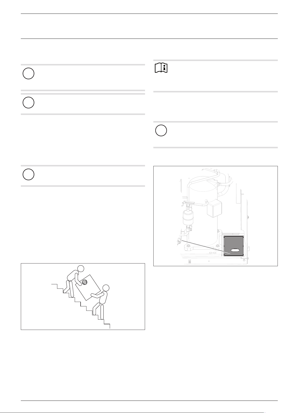
10.1 Transport
When transporting the appliance, be aware of its centre of
gravity.
- The centre of gravity is in the area where the compressor is
located.
- Lifting slings for handling the standard appliance can be
hooked in anywhere on the bottom of the frame.
Protect the appliance against heavy impact during transport.
- If the appliance needs to be tilted during transport, this must
only be for a short time and it must only be titled on one of
its longitudinal sides. When transporting the appliance, ensure the compressor is on the upper appliance side.
- The longer the appliance is tilted, the greater the distribution
of refrigerant oil in the system.
Wait approximately 30minutes before starting the appliance
after it has been tilted.
1
26_03_01_1727_
1 Knock-out "supply line entry"
Remove the knock-out "supply line entry" in the bottom of
the appliance.
Position the standard appliance on the prepared substrate.
Observe minimum clearances (see chapter "Preparations/
Minimum clearances").
D0000071298
www.stiebel-eltron.com WPL E | WPL cool | 11
INSTALL ATION
Installation
1
2
3
5
6
1 Pipe bend for heating circuit flow
2 Pipe bend for heating circuit return
3 Cable duct
4 Condensate drain hose
5 Concrete foundation
6 Coarse gravel back filling
Fit the pipe bends "heating circuit flow" and "heating circuit
return".
Route the supply pipes/cables from below through the knock-
out in the bottom and into the appliance.
Route the electrical cables in a cable duct.
4
10.2.2 Indoor installation
Position the standard appliance on the prepared substrate.
Pay attention to the air discharge direction.
Place the casing cover on the appliance and secure with two
screws.
6
5
4
3
1 "Heating flow" connection
2 "Heating return" connection
3 BUS cable
4 Control cable
26_03_01_0958_
5 Electric emergency/booster heater power cable
6 Appliance power cable
In the cover, cut out the pipe outlets for the "heating flow"
and "heating return" connections.
Route the pressure hoses from above through the cover and
into the appliance.
Route the electrical cables from above through the cable en-
tries and into the appliance.
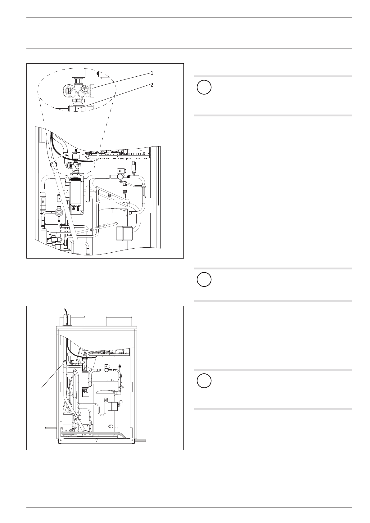
With the indoor installation, rotate the connector for the "heating
flow" connection through approx.145°.
1
2
26_03_01_0170
Material losses
!
Rodents may get into the appliance through the knock-
0
out aperture.
Close off the knock-out aperture.
12 | WPL E | WPL cool www.stiebel-eltron.com
INSTALL ATION
Installation
/
/
I
\
1 Connector
2 Union nut
Loosen the union nut.
Rotate the connector.
Retighten the union nut.
c
=:,,
dl,.<i;
~
1
10.3 Heating water connection
2
j
Structure-borne noise is largely prevented by the anti-vibration
construction of the heat pump and by the flexible pressure hoses,
which act as anti-vibration mounts.
26_03_01_0947_
10.3.1 Oxygen diffusion
Material losses
!
The heating system to which the heat pump is connected
0
must be installed by a qualified contractor in accordance
with the water installation drawings that are part of the
technical guides.
Before connecting the heat pump, flush the pipework thor-
oughly with suitable water. Foreign bodies, such as rust,
sand or sealant can impair the operational reliability of the
heat pump.
Connect the heat pump on the heating water side. Check for
tightness.
Connect the flexible pressure hoses to the connectors. The
pressure hoses must be at least 1 metre long.
Ensure that the heating flow and return are connected
correctly.
Provide thermal insulation in accordance with applicable
regulations.
When sizing the heating circuit, observe the internal pressure
differential (see chapter "Specification / Data table").
Material losses
!
Avoid open vented heating systems and underfloor heat-
0
ing systems with plastic pipes which are permeable to
oxygen.
1
1 Pipe bend for heating circuit return
Fit the "heating circuit return" pipe bend.
In underfloor heating systems with plastic pipes that are permeable to oxygen and in open vented heating systems, oxygen
diffusion may lead to corrosion on the steel components of the
heating system (e.g.on the indirect coil of the DHW cylinder, on
buffer cylinders, steel radiators or steel pipes).
With heating systems that are permeable to oxygen, separate
the heating system between the heating circuit and the buffer cylinder.
Material losses
!
The products of corrosion (e.g.rusty sludge) can set-
0
tle in the heating system components, which may result in a lower output or fault shutdowns due to reduced
cross-sections.
10.4 Second heat source
For dual mode systems, always connect the heat pump into the
return of the second external heat source, e.g. oil boiler.
26_03_01_0173_
www.stiebel-eltron.com WPL E | WPL cool | 13
 Loading...