

St George 5567800, 5566800, 5567100, 5566010 Installation Instructions
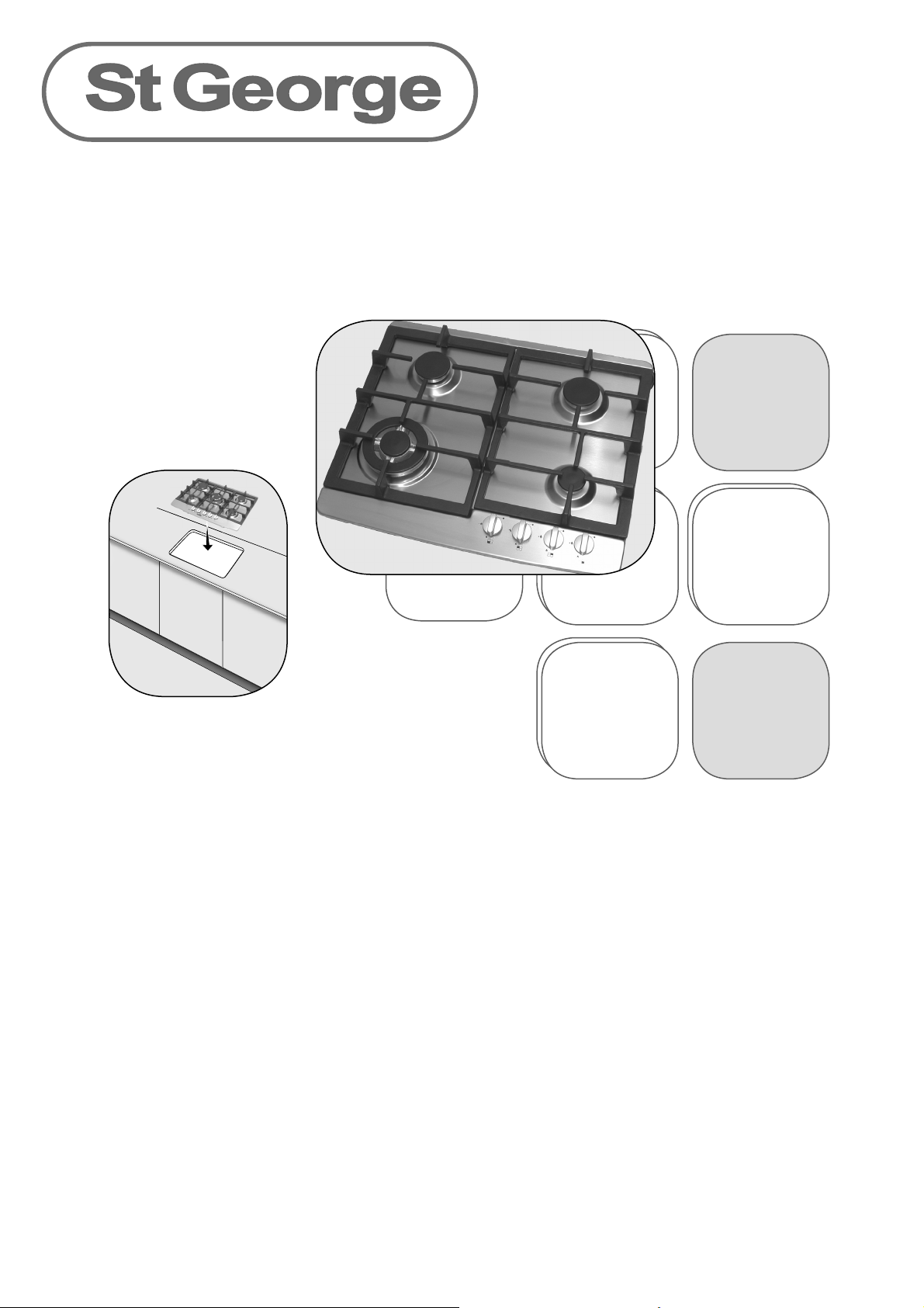
Gas Cooktops
Installation Leafl et
Model No’s
5567800 5 burner gas cooktop
5566800 4 burner gas cooktop
5567100 5 burner gas cooktop with fl ame failure
5566010 4 burner gas cooktop with fl ame failure
Safety Precautions
Before connecting to gas, ensure the cooktop is suited to the gas type required.
This cooktop shall not be installed on a boat or marine environment. This appliance shall not be
used as a space heater.
This appliance must be installed by a qualifi ed and competent person in accordance with the
gas installation code AS 5601, SAA Wiring Rules, as well as the requirements of all local statutory
and building authorities and regulations. The manufacturer does not accept any liability for any
damage or injury caused by improper installation.
Instruct The Customer
When satisfi ed that the cooktop has been installed and is operating correctly, instruct the
customer in its safe operation. Ensure the customer understands fully by having them operate the
cooktop.
This booklet must be left with the consumer.
Before Installation
Ensure Suitability Of Location
Before making any alterations to kitchen cabinetry, you should ensure that the proposed
location for the cooktop is suitable:
Electrical supply: there must be an earthed 240V 50 Hz 10Amp power socket within reach of the
supplied electrical cable (approximately 850mm from the rear right of the cooktop). The power
socket must be readily accessible without having to remove the appliance. If a power socket
needs to be installed or relocated, the work must be done by a licensed electrician.
Cabinetry: We recommend that the adjacent kitchen surfaces be capable of withstanding
temperatures of 100ºC, and that the cabinetry can support the weight of the cooktop plus fi lled
cooking utensils. If necessary, check with the bench top supplier that the material is suitable. St
George Appliances will not be liable for heat damage to incorrectly specifi ed materials.
Clearances: Ensure there is suffi cient room to install the cooktop with all required clearances as
specifi ed on the next page.
Gas Supply: Ensure that it is possible to run gas lines to the gas connection point of the
appliance. The gas connection point must be accessible without having to remove the
cooktop. If a fl exible hose is used, the connection point must also be accessible without having
to remove the cooktop.
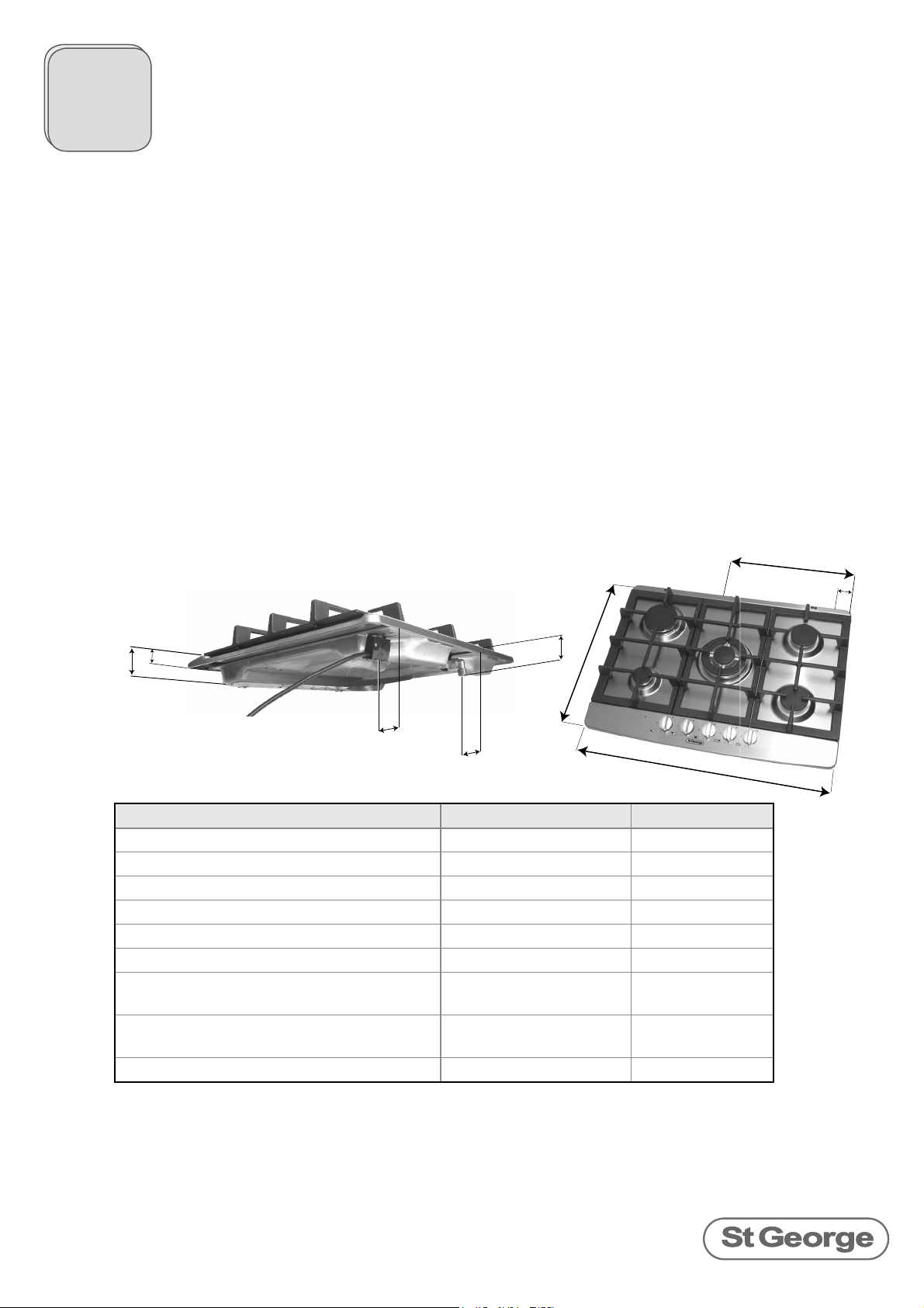
E
A
C
D
J
F
Dimensions 4 burner models 5 burner models
A - Depth
B - Width
C - Overall Height
D - Height above benchtop
E - Gas connection point to right edge
F - Gas connection point to back edge
G - Gas connection point to top surface
of hob
H - electrical junction (start of 1.4 metre
power cable) to right edge
J - electrical junction to back edge
G
B
512 mm 512 mm
595 mm 685 mm
45 mm 45 mm
19 mm 19 mm
362 mm 395 mm
41 mm 41 mm
62 mm 62 mm
28 mm 71 mm
62 mm 62 mm
H
2
Check Gas Type
Check that the gas type (ULPG or Natural Gas) available in the building matches the gas type
of the cooktop, as shown on the gas type sticker.
If the cooktop is suited to the incorrect gas type, it is possible to perform a gas conversion. This is
explained later in this manual.
Before Installation
Clearances
Overhead Clearances
Rangehoods and overhead exhaust fans must be installed with at least the clearances
•
recommended by the manufacturer’s instructions, but in all cases the clearance from the
top of the highest burner to a rangehood must be at least 650mm, and to an exhaust fan
must be at least 750mm.
Allow at least 650m clearance between the top of the highest burner and any overhead
•
cabinetry that is made of combustible material.
If the overhead cabinetry is made of non-combustible material such as tiles, the overhead
•
clearance must be at least 450mm.
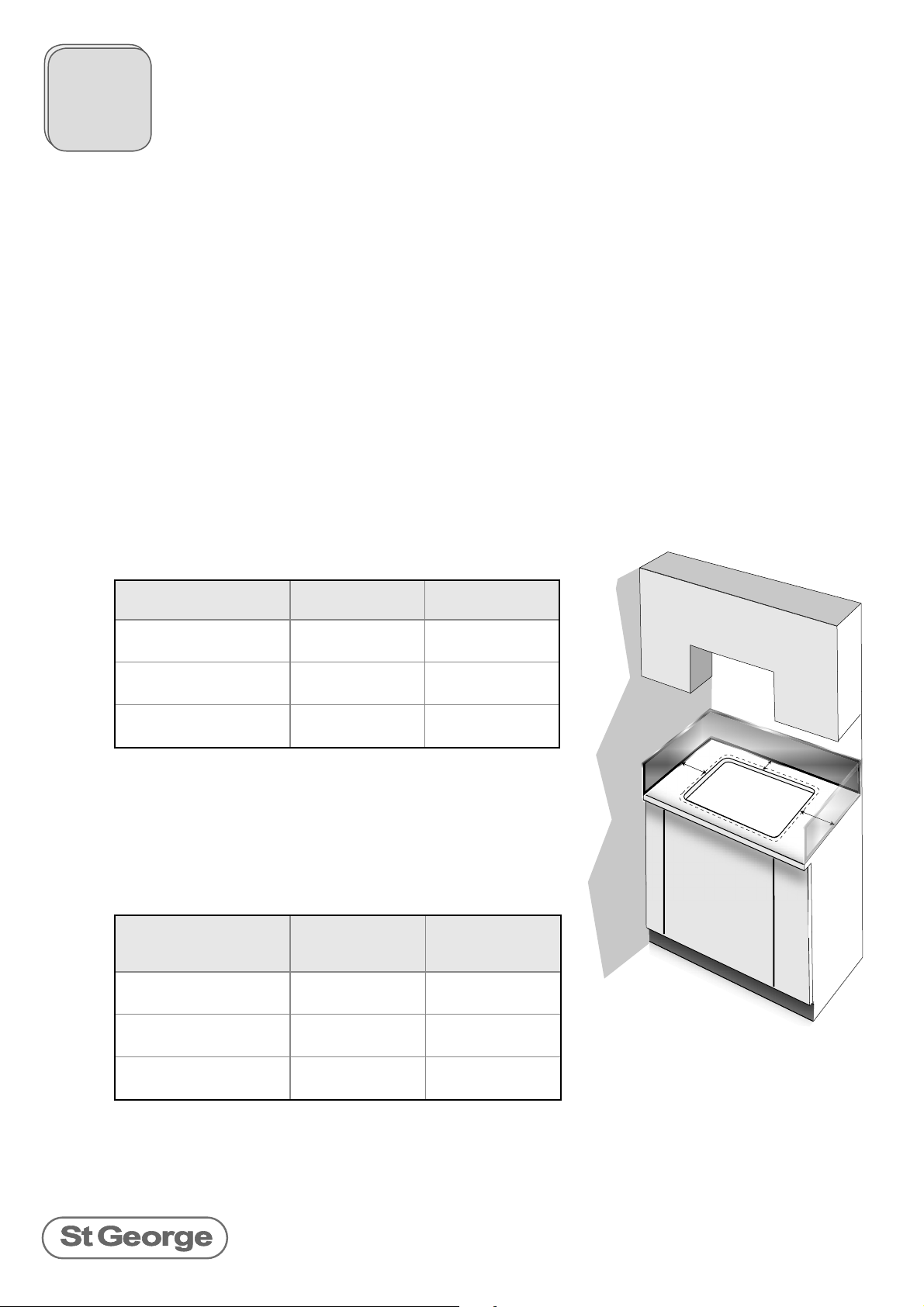
Side And Back Clearances From Combustibles
The clearance from combustible materials (including walls,
cupboards and curtains) must be at least 200mm as measured
from the far edge of the burners. For each model, this equates
to the following measurements from the edge of the cutout:
Clearance from cutout
to combustible wall
A - back edge to
back wall
B - left side edge to
left side wall
C - right side edge to
right side wall
600mm models 700mm models
120 mm 130 mm
165 mm 185 mm
125 mm 170 mm
Side And Back Clearances From NON-Combustibles
If the wall is made of non-combustible material, the required
clearance is only 10mm all around the perimeter of the
cooktop. For each model, this equates to the following
measurements from the edge of the cutout:
Clearance from cutout
to NON-combustible
wall
A - back edge to
back wall
B - left side edge to
left side wall
C - right side edge to
right side wall
A combustible wall can be protected with non-combustible
material such as 5mm thick ceramic tiles, as long as this
protection is at least 150mm high, and extends for the full width
and depth of the cooktop.
600mm models 700mm models
20 mm 20 mm
30 mm 75 mm
30 mm 75 mm
!"
#
3
 Loading...