

Stern Trendy 1000 T, Trendy 1000TB, Trendy 1000TE Installation And Maintenance Manual

1
INSTALLATION AND MAINTENANCE GUIDE
ELECTRONIC LAVATORY FAUCET
TRENDY 1000 T

INDEX
1 TECHNICAL DATA
2 TEMPERATURE ALTERNATIVES
3 PACK CONTENTS
4 PRE-INSTALLATION INFO
5-6 FAUCET INSTALLATION
7 ADJUSTING THE MIXED WATER TEMPERATURE
8-9 LIMITING THE MAXIMUM TEMPERATURE
10 TYPE 3 VALVES INFORMATION
12 SETTINGS ADJUSTMENT
13 BATTERY REPLACEMENT (BATTERY MODELS ONLY)
14 MAINTENANCE
Filters cleaning instructions
Care and cleaning of chrome and special finishes
15 TROUBLE SHOOTING
16 SPARE PARTS
17 WARRANTY
1
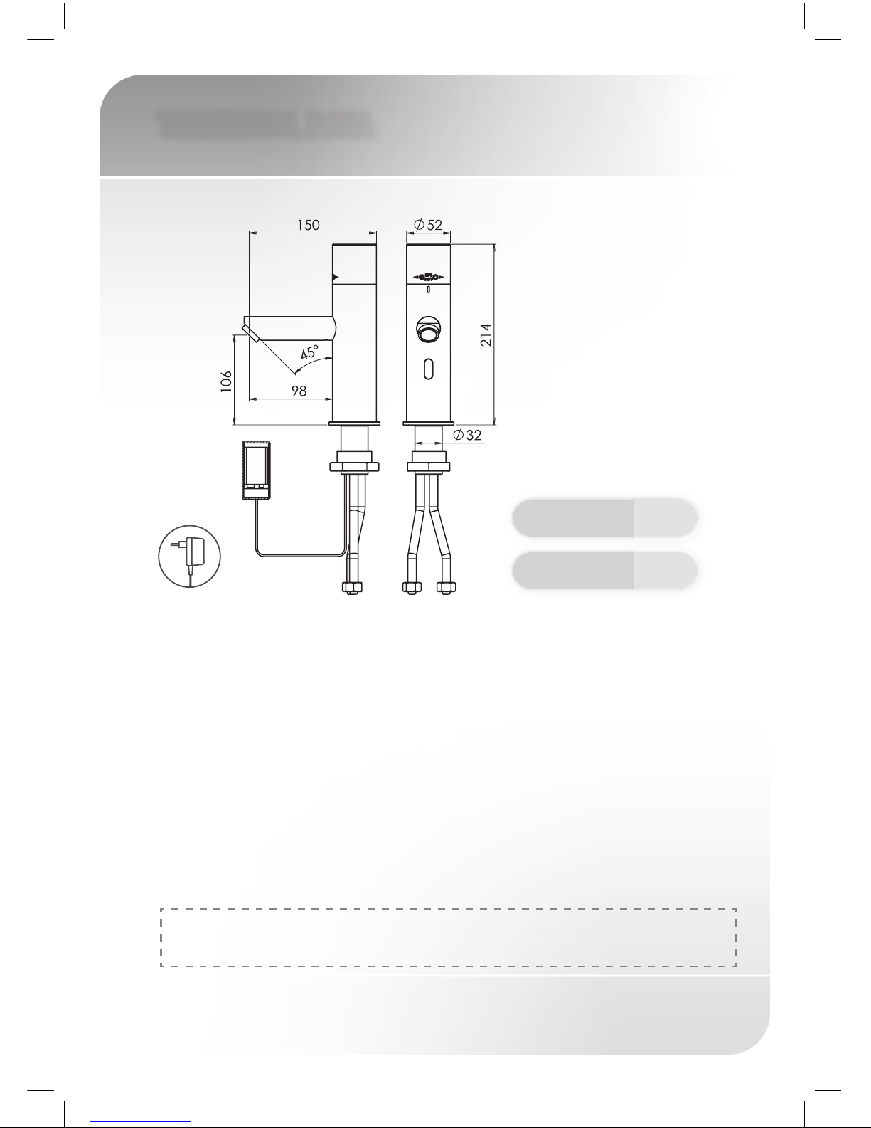
TECHNICAL DATA
Power supply: 9 V battery or 9 V transformer
Min Operating Water Pressure: 1 bar (14.5 PSI)
Max Operating Water Pressure: 5.0 bar (72.5 PSI)
With water pressure of more than 5 bars,
use a pressure reducing valve.
Sensor range: 170 mm. Adjustable with remote control.
Minimum sensor range: 50 mm
Maximum sensor range: 350 mm
Security time: 90 seconds. Can be reduced with the remote
control.
Hot water temperature: Max 70˚C
Trendy 1000 TB 236900
Trendy 1000 TE 236910
For Type 3 valves the supply conditions under section: ‘Type 3 valves
information’ takes precedence over this information.
2
TEMPERATURE ALTERNATIVES
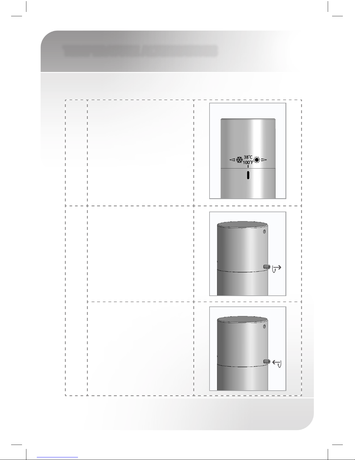
FIXED TEMPERATURE
Trendy 1000 T models includes a thermostatic mixer located in the faucet cap.
The mixer has been factory calibrated to 38°C.
Rotate the cap to the left to obtain cold
water and to the right to obtain hot
water.
MANUAL MIXER
To set a desired stable temperature:
Release the thermostatic mixing
cap by unscrewing the M4X6 screw
located behind the thermostatic cap,
using the 2mm Allen Key.
Set the desired temperature using a
thermometer and fasten the M4X6
screw all the way.
To regain the smooth rotation of the
cap, unscrew the cap bottom screw
partially.
3
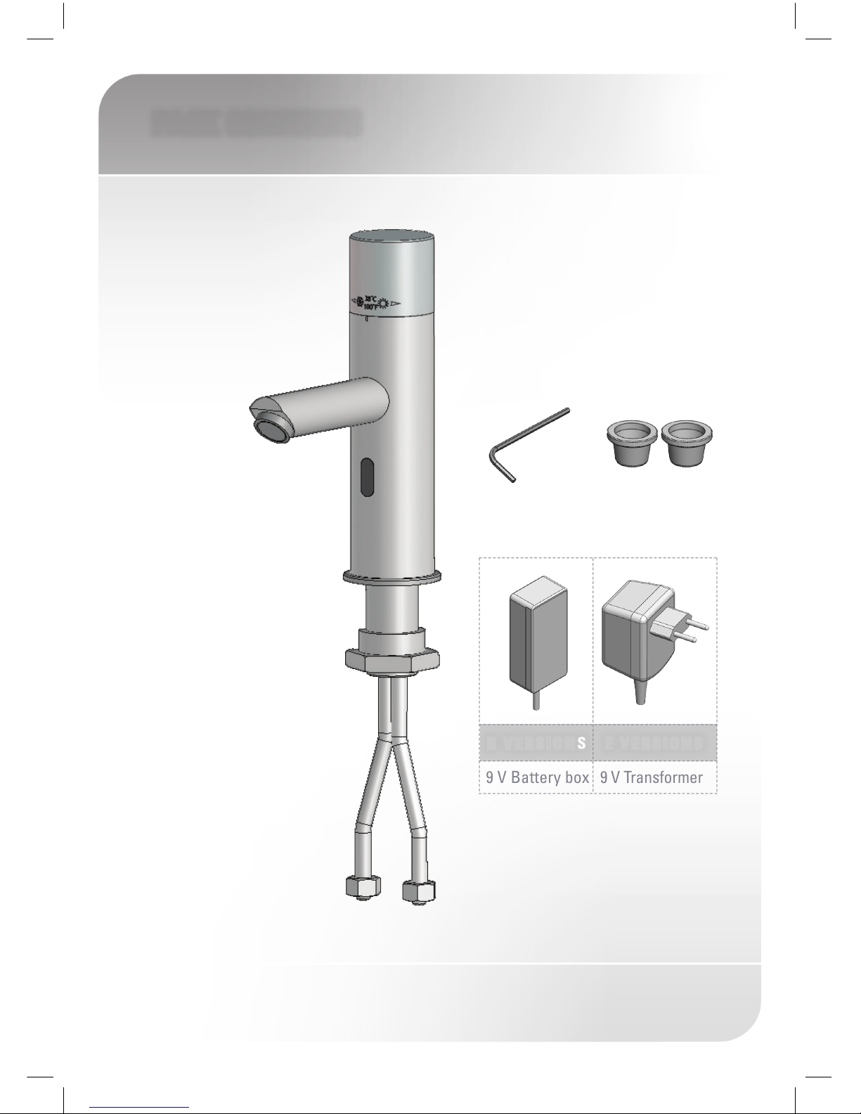
PACK CONTENTS
Familiarize yourself with the part names and confirm that the parts are
included.
1x Faucet and attachments
2 x Filters
1x Allen key
9 V Battery box
9 V Transformer
B VERSIONS E VERSIONS
4
PRE-INSTALLATION INFO
CHECK CONTENTS
Separate all parts from the packaging and check each part with
the pack contents section. Pay attention to the different models
variations.
Make sure all parts are accounted for before discarding any
packaging material.
If any parts are missing, do not attempt to install your electronic
faucet until you obtain the missing parts.
PREPARATION FOR INSTALLATION
Flush water supply lines thoroughly before installing the faucet.
Do not allow dirt, Teflon tape or metal particles to enter the faucet.
Shut off water supply.
IMPORTANT
All plumbing is to be installed in accordance with applicable
codes and regulations.
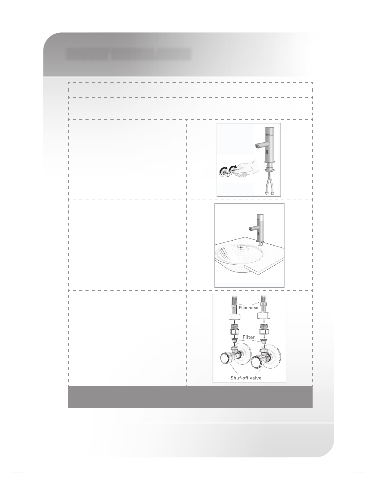
5
FAUCET INSTALLATION
Step 1 – Preparation for mounting the faucet
PAY ATTENTION: FOR TYPE 3 VALVES, MAKE SURE THAT ALL SITE REQUIREMENTS
CORRESPONDS TO THE INFORMATION GIVEN IN SECTION: ‘TYPE 3 VALVES INFORMATION’
Shut off water supply and remove the
hexagonal nut, the disk and the gasket.
Do not remove the O-ring from the base
of the faucet.
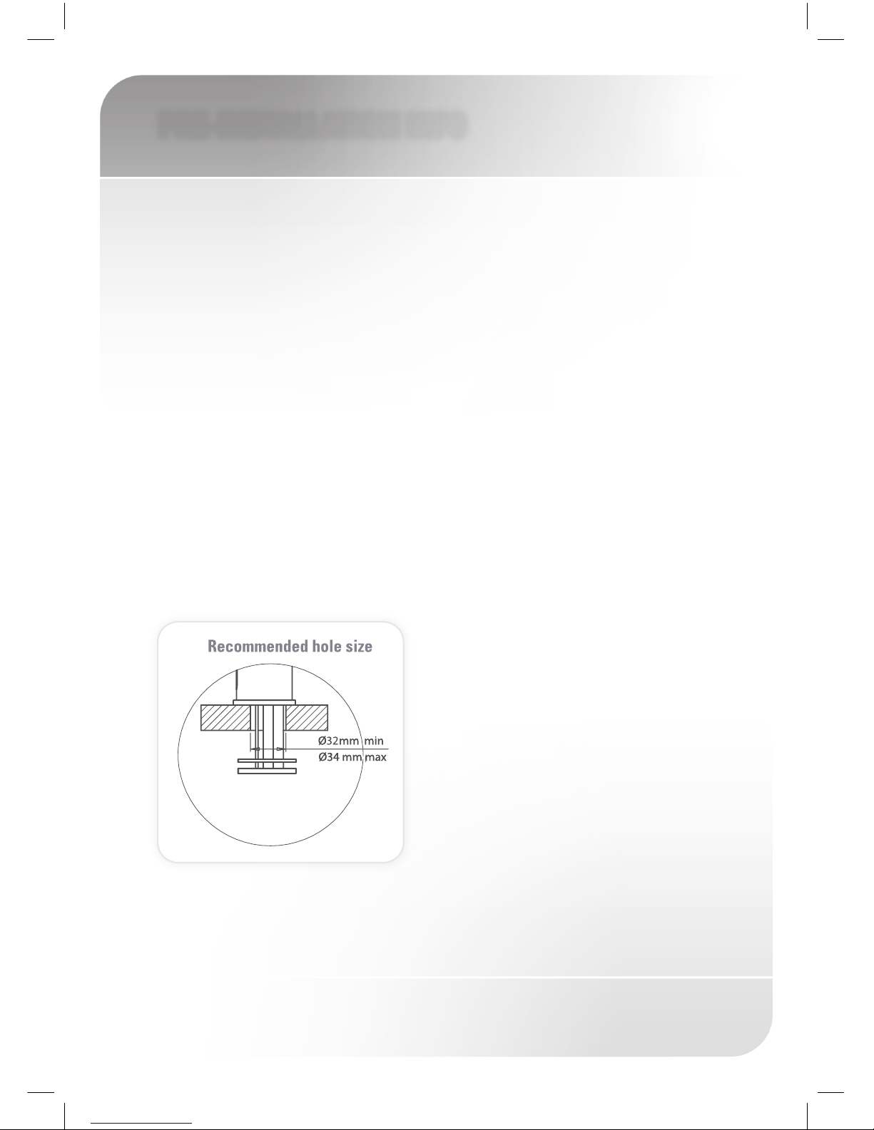
Step 2 – Installing the faucet
1. Place the faucet with O-ring into the
hole in deck or lavatory. Make sure the
O-ring is located between the deck or
lavatory and the bottom of the faucet.
2. Secure the faucet to deck or lavatory
with the hexagonal nut.
Step 3 – Connecting the water supply
1. Connect the red flexible pipe to the hot
water supply and the blue flexible pipe
to the cold water supply.
Note: the flexible hoses are equipped
with check valves to prevent back flow
of water into the shut off valve.
2. Turn on the central water supply and
the shut-off valves (angle valves)
3. Check for leaks.
MAKE SURE THAT THE FILTERS ARE INSTALLED BETWEEN THE FLEXIBLE
PIPE AND THE SHUT OFF VALVE (ANGLE VALVE) (NOT SUPPLIED).
6
FAUCET INSTALLATION
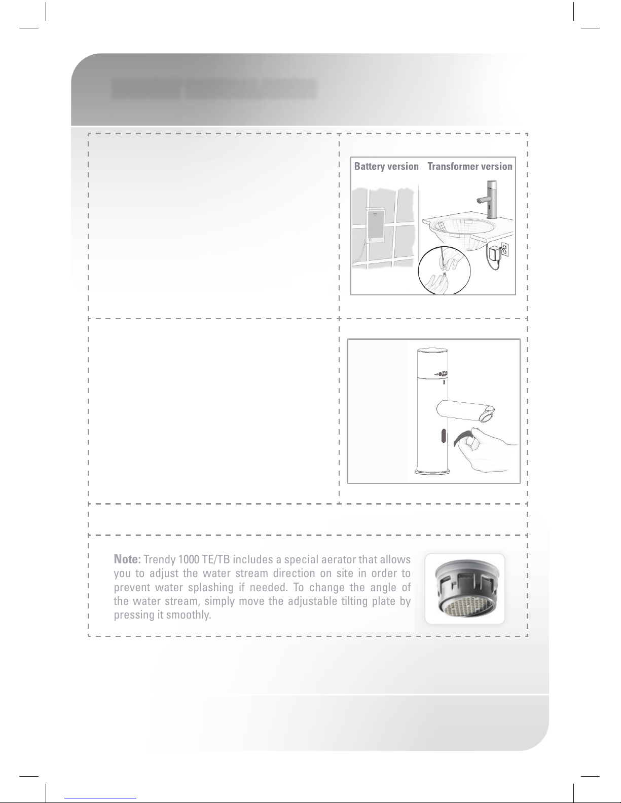
Step 4 - Connecting the power source
1. Connect the power source:
a. For battery versions: install the battery box at
the wall underneath the sink using the two sided
adhesive foam facet. The cable connection
must point down.
b. For transformer versions: Plug the transformer
into the electricity socket and connect the
connectors.
2. Remove the protecting sticker that covers the
sensor and wait 10 seconds before activating
the faucet.
IF THE RANGE IS UNSATISFACTORY, REFER TO THE SECTION TITLED
“SETTING ADJUSTMENT”.
Note: Trendy 1000 TE/TB includes a special aerator that allows
you to adjust the water stream direction on site in order to
prevent water splashing if needed. To change the angle of
the water stream, simply move the adjustable tilting plate by
pressing it smoothly.
 Loading...