

Page 1
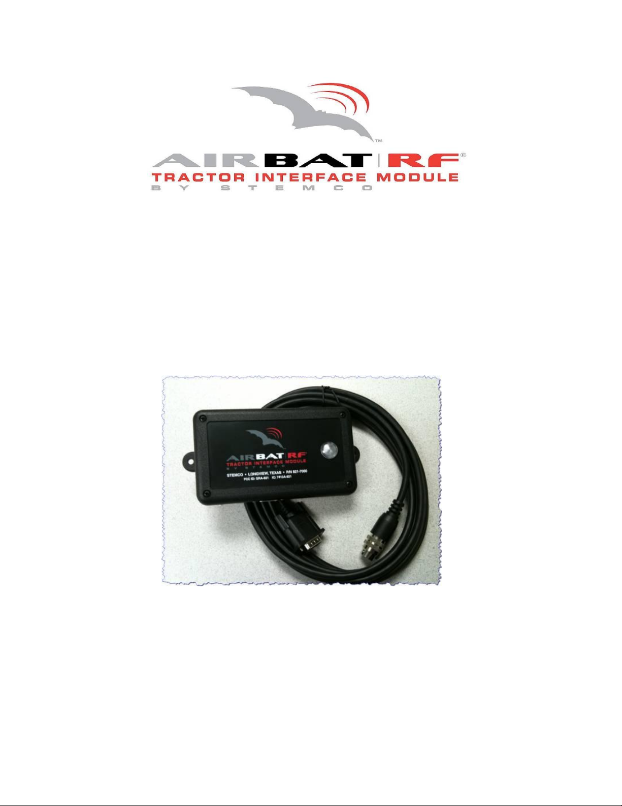
User Reference Guide
Tractor Interface Module
PeopleNet Interface
STEMCO Part #821-7000
Page 2

System Overview
The AirBAT Tractor Interface Module (TIM) is a state of the art wireless receiver designed to
keep drivers and maintenance personnel informed of tire issues in order to increase safety and
reduce costs. The TIM automatically receives and analyzes tire pressure data from AirBAT
sensors and issue alerts when a low tire condition is detected. The TIM notifies the driver via
the PeopleNet driver terminal and sends both SMS text and email alerts to the designated
recipients with date, time and location information. The TIM interfaces directly with the
PeopleNet g3 onboard computer system in order to pass information to the driver terminal and
to a PeopleNet network server. Data is then retrieved and acted upon by the BatRF WebBAT
application, which manages the alerts and aggregates the data for a given company ID.
Tractor Interface Module Features and Benefits
The TIM is designed to be easily installed and configured. Once the system is installed and set
up, you will begin to experience the benefits of real time tire pressure alert
Once you begin rolling down the road, you will begin to see the benefits of having real time tire
pressure alerts via the driver terminal, SMS text messages, and email.
WebBAT RF Information Manager
The WebBAT information management tool displays sensor data in actionable formats to
identify fleet conditions; problem vehicles; miles traveled; tire pressures; etc. Data can be
viewed as a web page, a .pdf file or a .cvs file format.
2
Page 3
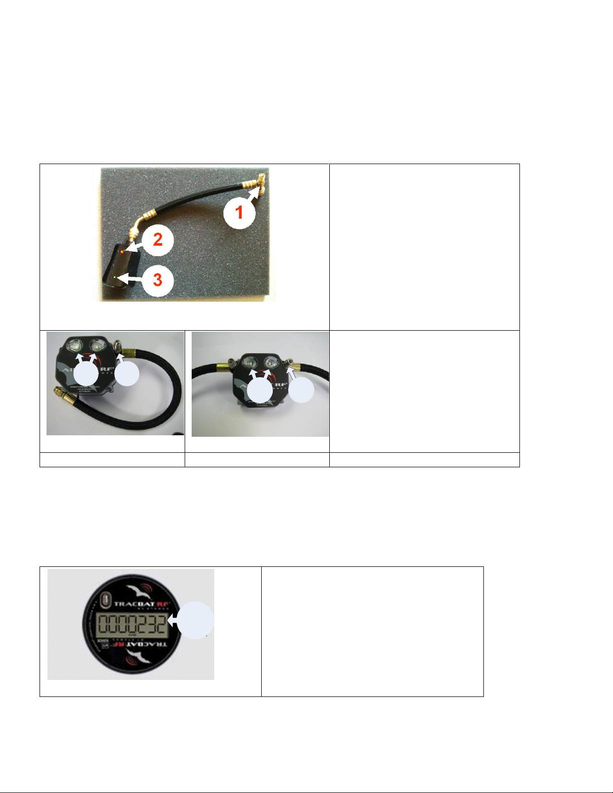
SST AirBAT
1. Fill Port – Provides easy
access fill point for air
chuck when filling the tire.
2. Visual Alert – Flashing
red LED indicates underinflated tires.
3. Health Indicator –
Flashing (every 5
seconds) green LED
indicates AirBAT is
operational.
1 2
1
2
1. Visual Alert – Flashing
red LED indicates underinflated tires
2. Fill Port - Provides easy
access fill point for air
chuck when filling the
tire.
Single-Tire AirBAT
Dual-Tire AirBAT
1
1. Visual Display of Miles traveled.
Sensors
AirBAT|RF® - Tire Pressure Monitor (TPM)
The AirBAT tire pressure monitoring sensor with visual LED display provides quick, on-tire
pressure identification. When mounted on the wheel end, the AirBAT continually monitors tire
pressures with visual alerts to indicate under-inflated tires.
TracBAT|RF – Electronic Hubodometer
Electronic mileage sensor with trip and life mileage feature: TracBAT’s mileage counting is
accurate within +/- 2%. TracBAT is often used to schedule maintenance by mileage activity
rather than time.
3
Page 4
Installation
Installation instructions are provided in a separate document, the Tractor Interface Module
Installation Guide, which can be downloaded at www.batrf.com.
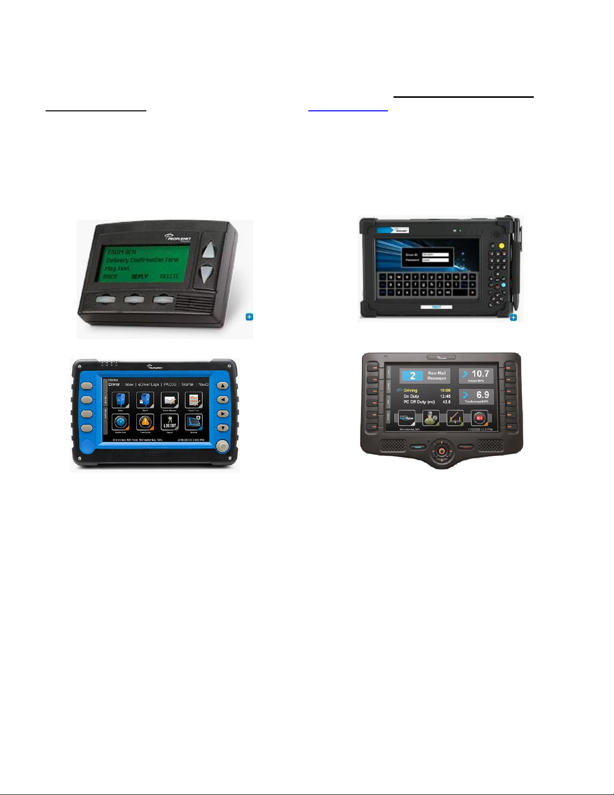
PeopleNet Driver Interfaces
PeopleNet offers a variety of driver interface options. However the majority of the terminals in the field
are the LCD type driver terminals. Due to the widespread use of these terminals, this is currently the
terminal that we will focus on for this manual.
LCD Driver Terminal Tablet
BLU BLU II
4
Page 5

PeopleNet (LCD) Driver Terminal
Display Line 1
Normal Operation
The TIM provides useful information on the first (top) line of the driver terminal to support
driver pre-trip inspections and help drivers to monitor alert conditions. This information will
always be sent to line one on the display but will only be visible by the driver/maintenance
personnel when the terminal is on the home screen. If the display is not on the home screen,
you can get there by simply pressing the ▲(up arrow) several times. After this action, you
should be able to see BatRF TPM information on line 1 of the display.
Pressure & System Status
The left half of the first line on the display provides summary information. concerning the
pressure status and if any faults are present.
First Character – The first character is used to show whether or not the TIM is operational
and communicating with the PeopleNet on board computer. The first character slowly flashes
on and off. This character can be any one of the following:
“*” – The system status is good and there are no faults present. All of the bound
sensor tire pressures are above the low pressure limit and the vehicle is not in motion.
“Slow Twirling Bar” – Same as * except vehicle is in motion.
“!” - Indicates that there is a low pressure alert or a system error. Typical pressure
alerts will be either a low or flat tire alert and a system error can occur when no GPS
data is available.
5
Page 6
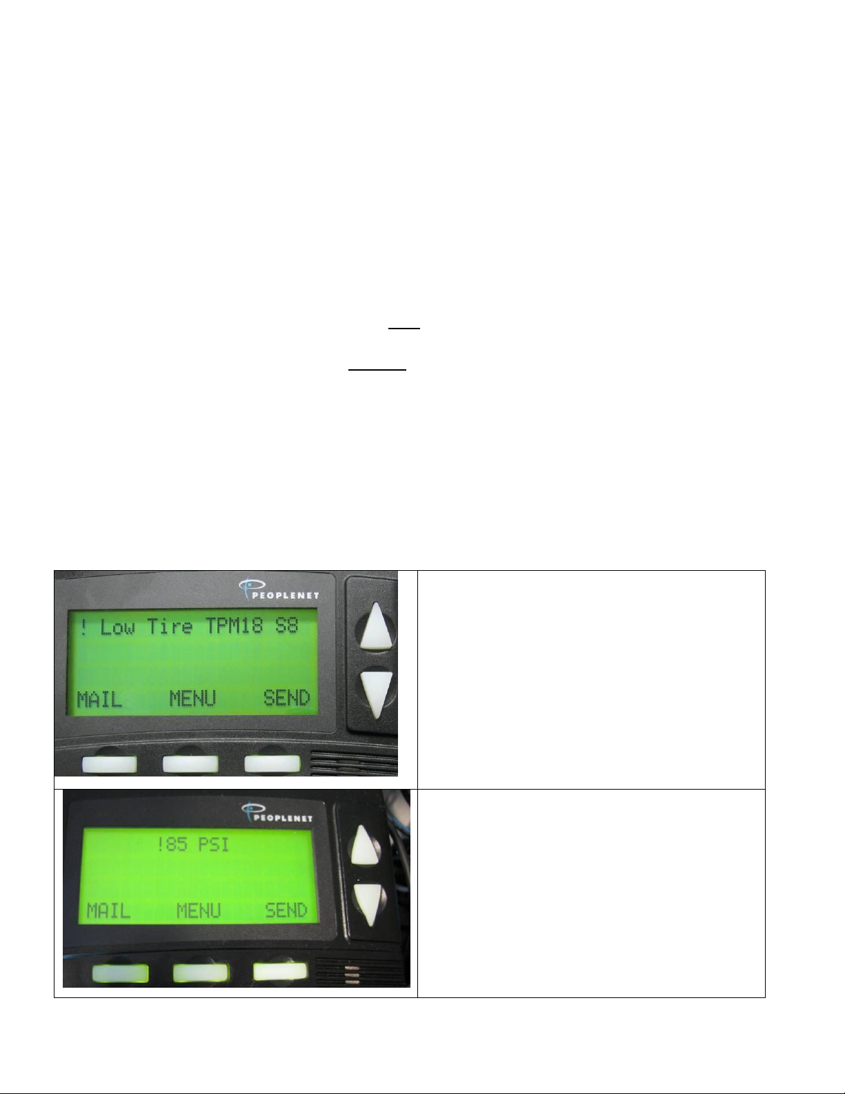
Pressure Alert Line 1
! {Alert Type} Tire TPM## S^^
The generic message will be displayed first
followed by one or more tire specifics. The
{Alert Type} will either be "Low" or "Flat"
depending on which criteria are meet. If
more than one tire is below the limit and one
is at a low level and the other is at the flat
level then the word "Flat" will be displayed.
Tire Pressure Specific Message
!###PSI
If one or more of the sensors that are bound
report pressures equal to or below the low limit
then the display will alternate between a warning
message and the tire with the lowest pressure.
*OK BatRF – This message indicates that all bound tires are above the low limit pressure. If
the “OK” is shown in upper case it means that the communications with WebBAT (a remote
web service that sends the email/SMS alerts is working correctly). If shown in lower case it
means the remote connection to WebBAT was not successful. The TIM periodically transmits
messages to WebBAT. When power is applied to the TIM, the status will show a lower case
“ok” until the TIM has successfully received a response back from WebBAT (usually takes less
than 5 minutes). When there are no alerts or errors the information is sent to line 1 passively;
in passive mode the driver can chose to display other line 1 items such as the clock and the
BatRF TIM will not cause the display to return to the TPM display.
Bound Tires/Sensors
“TPM##” - Where ## is the total number of tires (not sensors) that are currently bound to the TIM.
“S^^” - Where ^^ is the total number of sensors that are currently bound.
In Cab Alerts
Pressure Alert Line 1
After a full screen alert has been issued the alert information continues to update on line 1 of
the screen. When an alert is present the TIM forces the information to appear on line 1 (no
longer passively).
6
Page 7
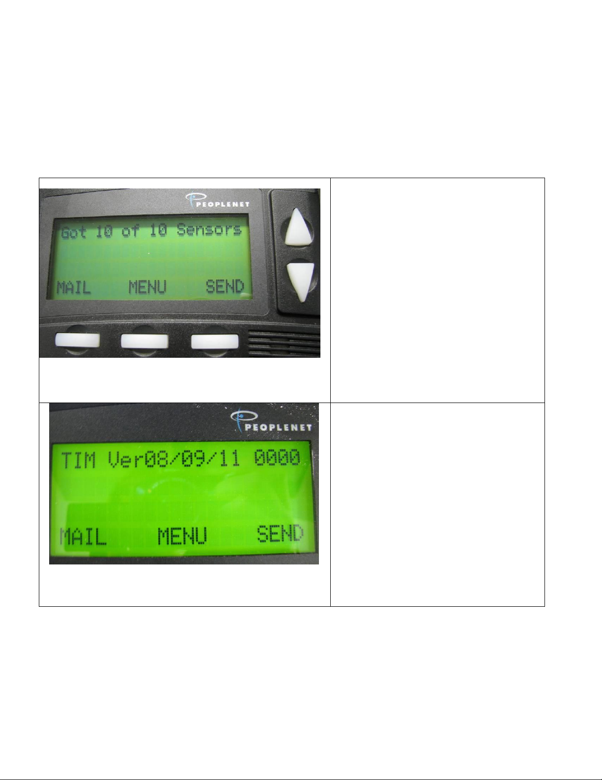
Startup Line 1 – Acquiring Bound
Sensors
Got ## of ### Sensors
Where first ## is the unique # of
sensors heard since the TIM has
powered up.
Where second ### is the total # of
sensors currently bound to the TIM
After all sensors are acquired or 30
seconds have transpired the firmware
version information will be displayed
on line 1.
Startup Line 1 – Firmware Version
Information
On boot the TIM displays its firmware
version (“Ver”) release date and a
configuration level (four digits on the
right). This information remains on the
screen for about 5 seconds before
changing to the normal running
information shown on line 1.
Power-Up Messages & Light Blink Pattern
Startup Line 1 - Sensor Present Verification
When the TIM powers up it must initialize by hearing the bound sensors over the wireless link
before it begins to display alert or error messages (like low or flat tires, no GPS, etc.). If no
sensors are bound then Got # of # screen is NOT displayed but instead the Status Line 1
display firmware version screen is shown.
When the PeopleNet On-Board Computer is powered up (normally by turning the tractor
ignition on) it takes about 5 seconds to initialize before providing power to the TIM. The TIM
initializes by flashing a green light about three times and then turns off the light. This indicates
that the TIM has had a normal startup. Occasionally, a short blue flash may be observed but it
shouldn't last more than 1 second. If other colors are observed refer to the troubleshooting
section in the appendix of this manual.
7
Page 8

Full Screen Alerts are issued when
a bound tire’s pressure is equal to
or less than the low pressure limit
set in the BatRF AirBAT.
! Flat or Low Tire Alert
! ## PSI
! Stemco’s BatRF TPM
ALL OK – If more than one alert
exists then pressing either the 1st or
2nd buttons labeled “All OK” will
acknowledge all the alerts.
OK - If more than one alert exists
then pressing the 3rd button labeled
“OK” will acknowledge only the alert
displayed; another alert will be
immediately issued.
If only one alert exists then pressing
any of the three buttons will have the
same result.
Full Screen Alerts
When the tractor is moving full screen pressure alerts are issued with an audible beep to alert
the driver. The driver may acknowledge the alert by pressing one of the three keys or wait 30
seconds and the full screen alert will clear automatically.
If the tractor is not moving full screens alerts are still issued for new low tires but without an
audible beep; which allows drivers who are sleeping in the sleeper birth from being
unnecessarily awakened due to a tire that has gone low.
The three levels of Tire Pressure Alerts:
1) Notify - Low or Flat Tire while tractor is not in motion. This is the lowest level of alert.
2) Concern – “Low Tire” with a pressure reading from the low limit to 12 PSI below the low
limit, while the tractor is in motion.
3) Critical – “Flat Tire” with a pressure reading greater than 12 PSI below the low limit while the
tractor is in motion.
Alerts can increase in level but do not decrease in level; they can be canceled from any level
by restoring the proper pressure for the under-inflated tire. A notify level alert will only escalate
if the tractor speed exceeds 25 mph; this allows drivers to perform their pre-trip inspection, find
a low tire, drive below 25 mph across the yard to an air chuck or tire repair station without an
alert escalation.
8
Page 9
Remote E-mail/SMS Text Alerts
Configuring Alerts
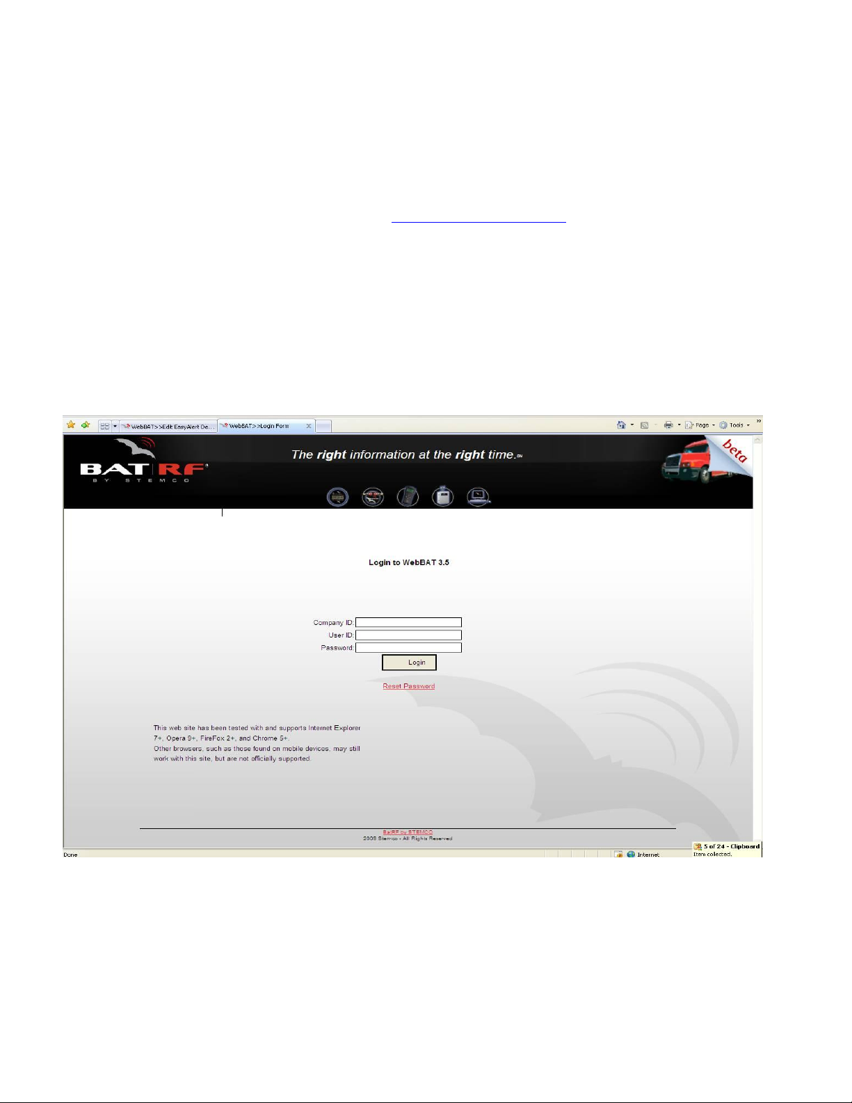
WebBAT Login
To configure a remote alert start by going to http://webbat.batrf.com/
The website will ask you for your
Company ID
User ID
Password
These should have been provided shortly after your request for service was submitted.
Once entered, click “Login”.
Note: If you don’t know your Company and/or User information, please contact your BatRF
salesperson.
9
Page 10

Setting Up Alert Destinations
After a successful log-in you should see the screen below:
Click the “Configuration” tab at the top right then the “Manage Alerts” tab to the left. When
you click on this tab it will give you five options. Select “Easy Alert Destinations”. Add you’re
Name and the E-mail address for alerts to be sent, and then select “Submit”. Or if you prefer
you can select the SMS radio button and enter the requested information for setting up text
destinations.
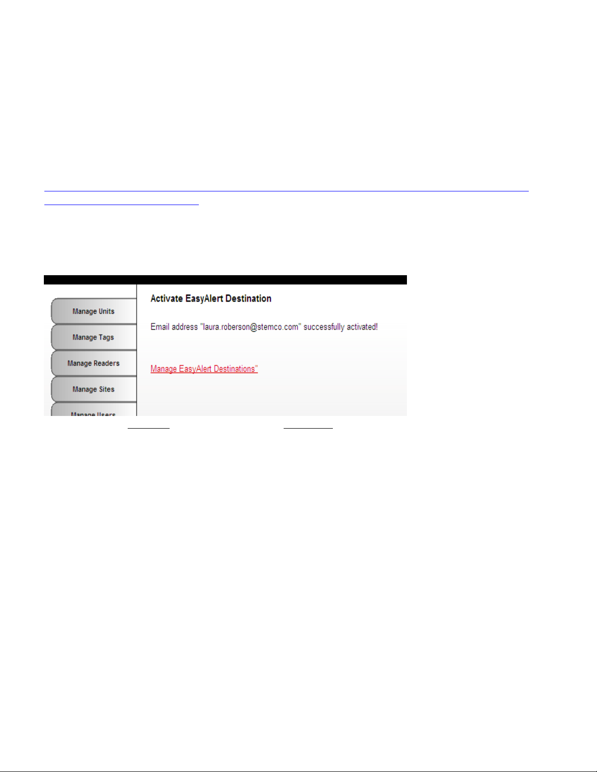
After submitting your Name and E-mail address you are automatically taken to the following
screen.
10
Page 11
Once you have received your Activation E-mail like the EXAMPLE below, you can click the link
to confirm your email address or or enter the Alert Destination Activation Code in the box
shown above and click “Activate”. SMS text messages must use the Enter Activation Code
here box to activate the SMS text address.
Sample Activation Email:
This email contains the activation code for this address.
To finish linking this account, click or copy and paste this link into your
browser:
http://nextgen.batrf.com/Forms/System/EasyAlertDestination.aspx?activ
ate=123F5SZN&conum=151
Or, enter this code in the Alert Destination Activation screen: 123F5SZN
Once the link is clicked or the code is entered in the box and you click “Activate”, the following
screen appears:
From here click top right tab “Configuration”, Left-hand tab “OBC”, then out of the three choices
given, click “Manage TIM Alerts”.
11
Page 12

Selecting Alert Message Destination
Once you have received your Activation E-mail your Name will be shown in the “Select
Message Destinations” pull-down menu below. Click on your name and it will transfer to the
“Currently Selected Destinations”. To modify alert start/end notifications you can check or
uncheck boxes near bottom of page. You will need to “Save” any changes you make to
Save/Cancel them.
From this screen click your top right “Configuration” tab, then click “Manage Alerts” tab on left
of page where you will be given five options. From these choose “Easy Alert Logs”.
12
Page 13

Alert Historical Log
From this screen click your top right “Configuration” tab, then click “Manage Alerts” tab on left
of page where you will be given five options. From these choose “Easy Alert Logs”.
13
Page 14

Sample E-mail/SMS Text Alerts
From: AlertsSystem@batrf.com [mailto:AlertsSystem@batrf.com]
Subject: BatRF Critical TPMS Alert for Vehicle #15-8084
Tire Pressure 95 PSI
Low Pressure Limit <= 95 PSI
Vehicle Information
Vehicle ID 15-8084 Type: Tanker
Wheel Position Right Axle #2 Lift Inner
Vehicle Speed 65 MPH Heading S 72deg W
Vehicle Location
14
Page 15
Detailed Information
Latitude 32.4349184N degrees | Longitude 94.7542528W degrees | Sensor SN 0974626.34/25_1 | Reader SN 604000EE
Sensor Read Date/Time Stamp 8/13/2011 2:16:17 PM UTC
webbat.batrf.com
15
Page 16

Automatic AirBAT Binding and Un-Binding Operation
A powerful feature of the Tractor Interface Module is its ability to automatically bind and unbind
AirBATs. This is most useful in drop and hook applications because the driver doesn’t have to
have any special training or be required to manually unbind and bind trailers as other products
in the marketplace require.
When a TIM is first installed it is not bound to any AirBATs. Driving the tractor causes the
tractor interface module to run its internal software algorithm called “the binding engine” to
evaluate each AirBAT signal received to determine which AirBATs are moving with the tractor
and which are present on other vehicles. After the binding occurs, the AirBATs are bound until
they meet the criteria for being unbound. Normal binding occurs within two (straight line
distance) miles of a tractors starting point. The tractor must have been motionless for at least
three minutes before moving for the binding engine to run. To minimize the opportunity to bind
to other AirBATs on adjacent vehicles on the interstate the binding engine only runs for the first
ten minutes of motion.
The unbinding engine runs at the same time as the binding engine. If an AirBAT is not heard
for four minutes while a tractor is in motion the AirBAT will be unbound from the TIM. AirBATs
will not be unbound when the tractor is motionless; nor will they be unbound when the TIM is
powered down (the TIM is powered by the PeopleNet On-Board Computer so when it powers
down the TIM also powers down).
Wheel Position Assignments
Wheel Positions can be assigned using WebBAT. Once assigned in WebBAT, wheel positions
automatically appear in text messages and email alerts. The wheel position assignments are
optional. Consult the WebBAT users guide to add wheel position assignments.
16
Page 17

Light
Description
Recommended Actions
Single Blinking
RED
Communication not working with
PeopleNet OBC
1) Review Installation Instructions for
OBC g3 services port configuration. 2)
Replace cable.
3) Call Stemco Customer Service
Double Blinking
RED
Communication working but PeopleNet
OBC is sending error codes to the TIM
which the TIM is not able to correct.
1) Call Stemco Customer Service
Solid BLUE
Boot Loader cannot find a valid firmware
image.
1) Call Stemco Customer Service
Blinking BLUE
Voltage supplied to the TIM is below 5
Volts.
1) Measure voltage on 9 pin D
connector end of cable. Pin 9 (from
+10 to +28VDC); pin 5 DC Common(-)
APPENDIX
Troubleshooting
Try the recommended actions to correct issues. Additional support is available by calling
Stemco customer support at 800-527-8492.
TIM – OBC Communications Issues
Symptom – Line 1 NOT shown on PeopleNet display & TIM Light is on or flashing
1) This indicates that the TIM is not communicating successfully with the OBC. Review
the installation instructions to ensure the g3 services port on the PeopleNet computer is
configured correctly. Ensure the cable is connected securely on both ends.
LED Indicator Codes
17
Page 18

TIM AirBAT Binding Issues
Symptom – TIM shows TPM0 S0 on display and won’t Bind to ANY AirBATs
1) No GPS Signal – If the TIM does not receive a good GPS signal it can’t bind to AirBATs.
The TIM indicates the presence of this error with a “!No GPS” message shown on Line 1 of
the display. Consult the PeopleNet OBC documentation to correct GPS connection issues.
2) The distance driven must be greater than 1 mile in less than 10 minutes (from the time
the truck first started to move) - It is important that the distance driven is more than 1 mile
away from the starting point. Driving around the block for 5 miles of odometer distance but
staying within 1 mile of your starting point will not work!
3) Though this is not likely to be the root cause, if the ignition wire to the PeopleNet Onboard computer is not connected then the speed reported to the TIM by the OBC is zero
and thus binding will not occur. If this is the case the TIM would not bind to any AirBATs.
Symptom – TIM binds to some AirBATs but the most distant AirBATs do not bind
Consult the installation instructions for recommendations on the best mounting location,
reposition the TIM as needed and then drive the tractor to bind to the AirBATs. If binding
issues still persist; call Stemco customer service for additional assistance.
Display Line 1 Error Messages
If errors occur the TIM will communicate those on the first line of the display. The following
error messages are supported:
! No GPS – The TIM uses the GPS to determine when to perform binding and unbinding
operations. If the GPS information is not present then the TIM will not bind or unbind sensors.
You may see this message momentarily when passing under a large underpass or tunnel. If
the tractor is parked under a roof this condition may persist indefinitely or may appear and
disappear based on the GPS receivers ability to lock onto enough satellites. If the message
persists review the PeopleNet documentation to determine how to correct the GPS failure.
This error is suppressed for the first 100 seconds on power up to allow the GPS time to lock
onto the satellites.
18
Page 19

FreeRTOS Modified GPL License Disclosure
The TIM firmware utilizes the FreeRTOS v6.0.5 Real Time Kernel which can be found on the
World Wide Web at http://www.freertos.org
Per the modified GPL license agreement, Stemco will provide a copy of the source code to
customer’s who request it. The source code provided is limited to the FreeRTOS supplied files
and any modifications Stemco has made but does NOT include Stemco application specific
files or information.
Operating Specs
19
Page 20

Certifications
FCC (USA)
This unit complies with Part 15 of the FCC Rules. Operation is subject to the following two conditions: (1) this device may
not cause harmful interference, and (2) this device must accept any interference received, including interference that may
cause undesired operation.
FCC ID: SRA-821
This equipment has been tested and found to comply with the limits for a Class B digital device, pursuant
to Part 15 of the FCC Rules. These limits are designed to provide reasonable protection against harmful interference in a
residential installation. This equipment generates uses and can radiate radio frequency energy and, if not installed and used in
accordance with the instructions, may cause harmful interference to radio communications. However, there is no guarantee
that interference will not occur in a particular installation. If this equipment does cause harmful interference to radio or
television reception, which can be determined by turning the equipment off and on, the user is encouraged to try to correct
the interference by one or more of the following measures:
-- Reorient or relocate the receiving antenna.
-- Increase the separation between the equipment and receiver.
-- Connect the equipment into an outlet on a circuit different from that to which the receiver is connected.
-- Consult the dealer or an experienced radio/TV technician for help.
Note: The manufacturer is not responsible for any radio or TV interference caused by unauthorized modifications to this
equipment. Such modifications could void the user’s authority to operate the equipment.
The antenna(s) used for this transmitter must be installed to provide a separation distance of at least 20 cm from all persons
and must not be co-located or operating in conjunction with any other antenna or transmitter. Users and installers must be
provided with antenna installation instructions and transmitter operating conditions for satisfying Rf exposure compliance.
Should you need any additional assistance with any problems or issues please contact STEMCO Customer Service at (800)
527-8492.
Industry Canada
Contains/Contient IC: 7413A-821
Notice: This device complies with Industry Canada licence-exempt RSS standard(s). Operation is subject to the
following two conditions: (1) this device may not cause interference, and (2) this device must accept any
interference, including interference that may cause undesired operation of the device.
Avis: Cet appareil est conforme avec Industrie Canada RSS standard exempts de licence (s). Son fonctionnement
est soumis aux deux conditions suivantes: (1) cet appareil ne peut pas provoquer d'interférences et (2) cet appareil
doit accepter toute interférence, y compris les interférences qui peuvent causer un mauvais fonctionnement du
dispositif.
an EnPro Industries company
P.O. Box 1989 • Longview, Texas 75606-1989 • (903)758-9981 • FAX 1-800-527-8492 www.BatRF.com
STEMCO, BAT RF, HandBAT, AirBAT and TracBAT are trademarks
20
 Loading...