

Page 1
Installation Instructions for AirBAT SST® RF – Single, Steer,
and Tag Axle Tire Applications
English
WARNING! Always use appropriate personal protective equipment (PPE)
during the installation and maintenance of the sensors and or related systems
on a vehicle. If you have questions regarding which PPE are appropriate, please
consult osha 3151-12r 2003 to determine appropriate equipment.
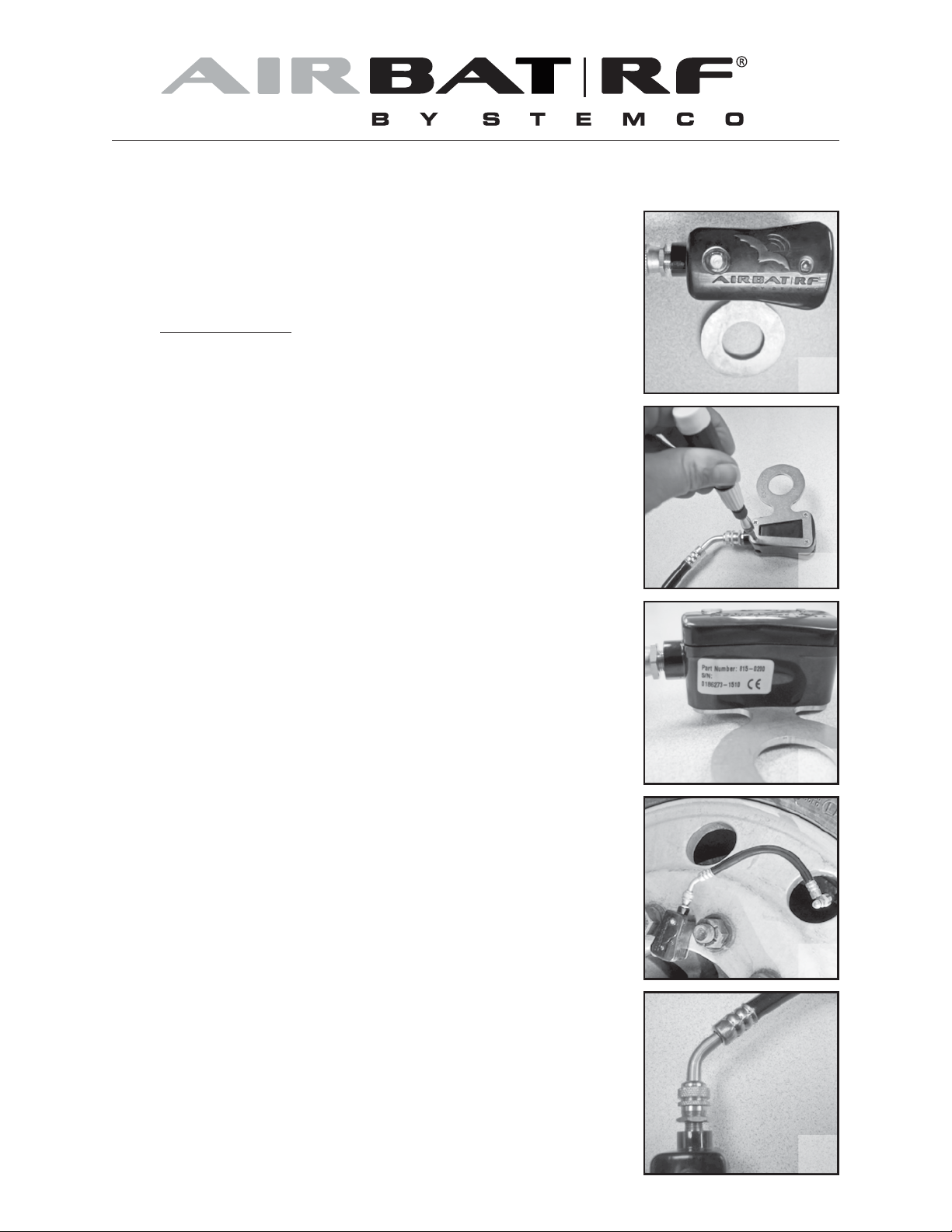
1. Choose the correct bracket for the application. Brackets are available for
steer tires, drive axles and a variety of trailer hubs/wheels. Figure 1 shows
a steer tire mounting bracket, hub-pilot wheel.
2. Attach the AirBAT SST to the bracket. Use the screws that are supplied with
the AirBAT SST. Tighten the screws with HAND TOOLS ONLY. Final
setting should be flush with the bottom of the bracket. See Figure 2.
3. Make a note of the unique serial number printed on the AirBAT SST label. See
figure 3.
installed (Left-Front, Right-Front, etc.). This information will be entered into
WebBat at a later time. (For WebBat users only)
4. Hold the bracket, with AirBAT SST attached, near the hub and visually select
a mounting stud on the hub so that the AirBAT hose will not be stretched or
be too loose, as shown in Figure 4. Remove the lug nut and slide the bracket
onto the wheel stud. Install and tighten the lug nut to the recommended
torque setting.
5. Remove any cap from the wheel’s valve stem. Be sure the threads are clean
and usable. Restore/replace stem if needed. Connect the AirBAT SST hose
to the valve stem and hand tighten the knurled nut to approximately ½ turn
past the point where the valve stem contacts the rubber gasket. Use a leakdetect bubble solution to ensure the connections do not leak.
Also note the position on the truck where the AirBAT SST is being
1
2
3
6. Check the tire pressure with the HandBAT reader or a conventional tire
gauge. The tire may be filled using the fill/check port on the AirBAT SST. The
HandBAT reading should confirm the unit’s serial number recorded in step 3.
Lastly, remove the cap on the fill port and depress valve core to verify flow,
then replace cap.
7
. The SST hose is replaceable. Ensure the jam nut on the AirBAT SST body is
tight against the fitting to prevent it from coming loose, as shown in Figure 5.
4
5
Page 2

USAGE:
If the Red LED on the AirBAT is blinking, it means that the tire’s air pressure is AT or BELOW the lower pressure threshold.
The threshold is a software function and can be changed with the HandBat reader. There is also a green led that blinks every
5 seconds in the smaller light pipe as an “I’m alive” indicator. The green light can only be seen if the unit is viewed closely
without direct sunlight.
RF INTERROGATION:
This unit can be read by the BatRF HandBat reader or Gate Reader System. The AirBat SST broadcasts information
(pressure and serial number) approximately every 2.5 seconds. For the Gate Reader System, a loop imbedded in the ground
activates the AirBAT SST and prompts it to transmit data. Finally, the BatRF, Driver Alert System (DAS) can be used in
conjunction with the AirBAT SST tire pressure sensor. All of the above mentioned equipment will operate with both single,
dual tire and SST AirBAT tire pressure sensors.
CERTIFICATIONS:
TThis unit complies with FCC Part 15. Operation is subject to the following two conditions: (1) this device may not cause
harmful interference, and (2) this device must accept any interference received, including interference that may cause
undesired operation.
FCC ID: SRA-816
This equipment has been tested and found to comply with the limits for a Class B digital device, pursuant to Part 15 of the FCC
Rules. These limits are designed to provide reasonable protection against harmful interference in a residential installation.
This equipment generates uses and can radiate radio frequency energy. If not installed and used in accordance with the
instructions it may cause harmful interference to radio communications. However, there is no guarantee that interference
will not occur in a particular installation. If this equipment does cause harmful interference to radio or television reception,
which can be determined by turning the equipment off and on, the user is encouraged to try to correct the interference by
one or more of the following measures:
- Reorient or relocate the receiving antenna
- Increase the separation between the equipment and receiver
- Connect the equipment into an outlet on a circuit different from that to which the receiver is connected.
- Consult the dealer or an experienced radio/TV technician for help.
This product meets the applicable Industry Canada technical specifications/Le present materiel est conforme aux specifications
techniques applicables d’Industrie Canada. IC:7413A-8150200
NOTE: The manufacturer is not responsible for any radio or TV interference caused by unauthorized modifications to
this equipment. Such modifications could void the user’s authority to operate the equipment. The antenna(s) used for this
transmitter must be installed to provide a separation distance of at least 20cm from all persons and must not be co-located
or operating in conjunction with any other antenna or transmitter. Users and installers must be provided with antenna
installation instructions and transmitter operating conditions for satisfying RF exposure compliance.
IMPORTANT NOTES:
This unit contains a Lithium-Thionyl Chloride battery and should be disposed of according to local regulations. The battery
contains less than 1 gram of lithium and is therefore classified as a non-hazardous product. Lithium-Thionyl Chloride batteries
contain no poisonous materials and do not present environmental hazards when properly disposed of.
an EnPro Industries company
STEMCO, BAT RF, and AirBAT are all registered
trademarks of STEMCO LP © 2014 P/N 093300085
TS 16949
STEMCO - USA
P.O. Box 1989
Longview, TX 75606-1989
(903) 758-9981 • 1800-527-8492
FAX: 1-800-874-4297
www.stemco.com
STEMCO - CANADA
5650 Timberlea Blvd. Unit B
Mississauga, ON L4W 4M6
(905) 206-9922 • 877-232-9111
FAX: 877-244-4555
 Loading...