

Page 1
)
SI-60 and SI-75 Models
%'("#%! ( $%%! (#%$
Subject to Change without Notification.
© 2012 Stellar Industries, Inc.
Stellar Industries, Inc.
190 State Street
PO Box 169
Garner, IA 50438
800-321-3741
Fax: 641-923-2811
www.stellarindustries.com
Last Revision: 05/25/12
Page 2

Stellar Cable Hoist Manual Revisions
Date of Revision Description of RevisionSection Revised
Page 3

Table of Contents
Table of Contents
Introduction...............................................................................iii
Chapter 1 - Safety ...................................................................1
Chapter 2 - Operation.............................................................3
General Guidlines for Operation of the Cable Hoist ...........4
Loading Operation...................................................................5
Unloading Operation - O.R. and I.O. Models .......................6
Unloading Operation - Extendable Tail Models....................7
Correct Roll-Off Container Loads...........................................8
Unsafe Roll-Off Container Loads ............................................8
Hoist Prop Operation................................................................9
Chapter 3 - Maintenance .....................................................11
Maintenance Procedures .....................................................11
Daily Inspection ......................................................................11
Monthly Inspection .................................................................11
General Service ......................................................................11
Inspection of Sheaves ............................................................12
Cable Replacement ..............................................................13
Choice Lubricants for DX Bearings .......................................14
Chapter 4 - Specifications ....................................................15
Cable Hoist Dimensions .........................................................16
Container Subframe...............................................................17
Chapter 5 - Decals ................................................................19
Decal Kit Placement ..............................................................19
Safety Decals of Note............................................................20
Chapter 6 - Installation..........................................................21
General Install Guidelines ......................................................21
Truck Chassis Specifications ..................................................22
Step 1: Truck Frame Cut-Off ..................................................22
Dimensions: 174 Models .........................................................23
Dimensions: 182 Models .........................................................24
Dimensions: 194 Models .........................................................25
Step 2: Mount Hoist.................................................................26
Step 3: Mount Lift Cylinders ...................................................27
Step 4: Hydraulic Reservoir Installation ................................28
Step 5: Sub-Frame Front Clamp Installation ........................29
Step 6: Hydraulic Plumbing Installation................................29
Step 7: Hydraulic Relief Pressure Setting ..............................30
Step 8: Cable Control Installation.........................................30
Step 9: Pneumatic Control Installation ................................32
Step 10: Bumper Installation..................................................34
Heavy Duty ICC Bumper Installation....................................35
Step 11: Hoist Up Light Installation ........................................36
Step 12a: Fender Installation - Steel Tandem/Tri-Axle ........37
Step 12b: Fender Installation - Plastic Tandem/Tri-Axle......38
Step 13: Mid-Body Light Installation......................................38
Step 14a: Removable Stop Installation................................39
Step 14b: Intermediate Stop Installation .............................40
Step 15: Reflective Tape Installation ....................................41
Chapter 7 - Hydraulics - Electrical ......................................43
Hydraulic Schematic ..............................................................43
Hydraulic Routing - Standard Lift Cylinder ..........................44
Hydraulic Routing - Telescopic Lift Cylinder ........................45
Hydraulic Routing - Reverse Mount Lift Cylinder.................46
Reverse Mount Lift Cylinder Mounting Kit - PN 56094 ........47
Reverse Mount Lift Cylinder Mounting Kit - PN 56094 ........48
Hydraulic Routing - Reeving Cylinder ..................................49
Hydraulic Routing - Tail Extension IOX Cylinder Mount ......50
Hydraulic Routing - Tail Extension ORX Cylinder Mount .....51
Electrical Schematics .............................................................52
Chapter 8 - Assembly Drawings...........................................53
Cable Controls........................................................................53
Air Controllers Assembly 1......................................................54
Air Controllers Assembly 2......................................................55
Main Hoist Assembly ...............................................................56
Reeving Cylinder Assembly - PN 60219................................57
Reeving Cylinder Assembly - PN 60221................................57
Chassis Mounted Parts ...........................................................58
Chassis Mounted Parts ...........................................................59
Mounting Kit (Forward Mount) - PN 55261...........................60
Mounting Kit (Reverse Mount) - PN 56094 ...........................61
Mounting Kit (Telescopic) - PN 55265...................................62
Cab Guard - PN 47263...........................................................63
Under Body Tool Box - PN 46579 ...........................................64
Reservoir Assembly - PN 46133 ..............................................65
2 Section Valve Bank Reservoir - PN 45710 ..........................66
3 Section Valve Bank Reservoir - PN 46642 ..........................67
Reservoir Mounting Bracket for PN 45710............................68
Standard Lighted Bumper - PN 45887 ..................................69
Pintle Bumper - PN 46818.......................................................70
ICC Wide Bumper - PN 53397 ...............................................71
ICC Heavy Duty Bumper - PN 46809 ....................................72
ICC Bumper Weldment - PN 45574.......................................73
ICC Standard Narrow Bumper - PN 48848...........................74
ICC Narrow Bumper - PN 48846............................................75
ICC Extendable Bumper - PN 62663.....................................76
Tri-Axle Fenders - PN 46299 ....................................................77
Tandem Fenders - PN 46122 ..................................................78
Tandem Fenders - PN 46122 Continued... ...........................79
Tandem Poly Fenders - PN 45795..........................................80
Tri-Axle Poly Fenders - PN 45893 ............................................81
Telescopic Lift Cylinder - PN 51078 .......................................82
Standard Lift Cylinder - PN 55262 .........................................82
Long Reeving Cylinder - PN 51201 .......................................83
Standard Reeving Cylinder - PN 51080 ................................83
Tail Extension Cylinder - PN 51203.........................................84
Tail Extension Cylinder - PN 51202.........................................84
Ratchet Strap Kit - PN 63150..................................................85
Bolted Hold Down (Optional) - PN 42918 ............................86
Chapter 9 - Replacement Parts..........................................875
Page 4

Stellar Cable Hoist Owner’s Manual
AN OVERVIEW TO OWNER, OPERATOR AND
SERVICE PERSONNEL ABOUT SAFETY
As the owner or employer, it is your responsibility to instruct the operator in the safe operation of this equipment and to provide the operator with properly maintained equipment.
FAILURE TO READ THIS MANUAL BY ANYONE WHO WILL OPERATE, SERVICE, OR WORK
AROUND THIS CABLE HOIST IS A MISUSE OF THE EQUIPMENT. DEATH OR SERIOUS INJURY
WILL RESULT FROM IMPROPER USE OR MAINTENANCE OF THIS MACHINE.
Occupational safety is a prime concern of Stellar Industries in the design and production
of this cable hoist. Our goal in writing this manual was the safety of the operator and others who work around this equipment.
It is your responsibility to know the specific requirements, governmental regulations, precautions and work hazards that exist in the operation and maintenance of this cable
hoist. You shall make these available and known to all personnel working with and
around the equipment, so that all of you will take the necessary and required safety precautions.
FAILURE TO HEED THESE INSTRUCTIONS CAN RESULT IN SERIOUS INJURY OR DEATH.
It is also your responsibility to operate and maintain your cable hoist with caution, skill,
and good judgment. Following the recognized safety procedures will help you avoid
accidents. Modification to any part of his cable hoist can create a safety hazard and
therefore shall not be made without the manufacturer’s written approval. Use only factory approved accessories, options, and parts on this equipment. The rebuilding or remounting of this equipment requires the mounting procedures and retesting to be in accordance with factory instructions. Safety covers and devices must remain installed and
maintained in proper working condition. Safety decals must be maintained, be completely legible, and be properly located. If safety covers, devices, or decals are missing,
they must be replaced with the proper designated Stellar part.
Be capable, careful, and concerned! Make safety your everyday business!
Attention!
According to Federal Law (49 cfr part 571),
each final-stage manufacturer shall complete the vehicle in such a manner that it
conforms to the standards in effect on the
date of manufacture of the incomplete
vehicle, the date of final completion, or a
date between those two dates. This requirement shall, however, be superseded by any
conflicting provisions of a standard that
applies by its terms to vehicles manufactured in two or more stages.
Therefore, the installer of Stellar cable hoists
is considered one of the manufacturers of
the vehicle. As such a manufacturer, the
installer is responsible for compliance with all
applicable federal and state regulations.
They are required to certify that the vehicle
is in compliance with the Federal Motor
Vehicle Safety Standards and other regulations issued under the National Traffic and
Motor Vehicle Safety Act.
Please reference the Code of Federal
Regulations, title 49 - Transportation, Volume
5 (400-999), for further information, or visit
www.gpoaccess.gov/nara/index.html for
the full text of Code of Federal Regulations.
Page 5

Introduction
Introduction
Stellar Cable hoists are designed to provide
safe and dependable service for a variety
of operations. With proper use and
maintenance, these cable hoists will
operate at peak performance for many
years.
To promote this longevity, carefully study the
information contained in this manual before
putting the equipment into service. Though
it is not intended to be a training manual for
beginners, this manual should provide solid
guidelines for the safe and proper usage of
the cable hoist.
Once you feel comfortable with the
material contained in this manual, strive to
exercise your knowledge as you safely
operate and maintain the cable hoist. This
process is vital to the proper use of the unit.
A few notes on this manual:
A copy of this manual is provided with every
cable hoist and shall remain with the cable
hoist at all times. Information contained
within this manual does not cover all
maintenance, operating, or repair
instructions pertinent to all possible situations.
Please be aware that some sections of this
manual contain information pertaining to
Stellar manufactured cable hoists in general
and may or may not apply to your specific
model.
This manual is not binding. Stellar Industries,
Inc. reserves the right to change, at any
time, any or all of the items, components,
and parts deemed necessary for product
improvement or commercial/production
purposes. This right is kept with no
requirement or obligation for immediate
mandatory updating of this manual.
In closing:
If more information is required or technical
assistance is needed, or if you feel that any
part of this manual is unclear or incorrect,
please contact the Stellar Customer Service
Department by phone at 800-321-3741 or
email at service@stellarindustries.com.
ATTENTION
Failure to adhere to the
instructions could result in
property damage or even serious
bodily injury to the operator or
others close to the cable hoist.
For Technical Questions, Information, Parts, or Warranty, Call Toll-Free at
800-321-3741
Hours: Monday - Friday, 8:00 a.m. - 5:00 p.m. CST
Or email at the following addresses:
Technical Questions, and Information service@stellarindustries.com
Order Parts parts@stellarindustries.com
Warranty Information warranty@stellarindustries.com
Page 6

& Stellar Cable Hoist Owner’s Manual
Page 7

Chapter 1 - Safety
Safety
Please Read the Following Carefully!
This portion of the manual contains information regarding all Stellar manufactured
Cable Hoists. Some items contained within
this chapter may not apply to your specific
equipment.
Safety should be the number one thought
on every operator’s mind. Three factors
should exist for safe operation: a qualified
operator, well-maintained equipment, and
the proper use of this equipment. The following information should be read and
understood completely by everyone working with or near the Cable Hoist prior to putting the unit into operation.
Please take note that Stellar Industries, Inc.
is not liable for accidents incurred by the
Cable Hoist because of non-fulfillment from
the operator’s side of current rules, laws,
and regulations.
General Safety
It is the responsibility of the owner to instruct
the operator in the safe operation of your
equipment and to provide the operator
with properly maintained equipment.
Trainees or untrained persons shall be under
the direct supervision of qualified persons.
Always wear the prescribed personal safety
devices.
Always wear approved accident-prevention clothing such as: protective helmets,
anti-slip shoes with steel toes, protective
gloves, anti-noise headphones, protective
glasses, breathing apparatus, and reflective
jackets. Consult your employer regarding
current safety regulations and accidentprevention equipment.
Do not wear rings, wristwatch, jewelry,
loose-fitting or hanging clothing such as ties,
torn garments, scarves, unbuttoned jackets
or unzipped overalls, which could get
caught up in the moving parts of the Cable
Hoist.
Keep a first-aid box and a fire extinguisher
readily available on the truck. Regularly
check to make sure the fire extinguisher is
fully charged and the first-aid kit is stocked.
Do not use controls and hoses as handholds. These parts move and cannot provide stable support.
Do not allow unauthorized personnel or
equipment to enter within 10 feet of Cable
Hoist operating area.
Do not operate equipment under the
adverse influence of alcohol, drugs, or
medication.
Read all safety decals on the equipment
and understand their meaning.
Personal Safety
Keep clear of all moving parts.
Never allow anyone under any portion of
the hoist unless the hoist is firmly resting in
the hoist props.
Never allow anyone to ride the Cable Hoist
or load.
Operation Safety
Never operate the hoist unless the hydraulic
system, including the cylinders and lines, are
full of oil and free of air.
Check the area for power lines and overhead obstructions.
Do not load, dump or unload a container
on uneven ground.
Page 8

Stellar Cable Hoist Owner’s Manual
Do not move the truck while the hoist and
container are raised. A raised load creates
a top heavy unstable load.
Do not use a chain between the reeving
cable and the container. A chain will not
withstand the force applied to the cable.
Do not use any method to hold a valve
open which will not let the valve close automatically when released.
Always keep the cable centered on the
hoist frame. Do not allow the cable to rub
on any surface when loading or unloading
a container.
Do not operate the reeving cylinders to
load or unload a container unless the front
of the hoist frame is above the top of the
truck cab.
Maintenance Safety
Never modify or alter any of the equipment,
whether mechanical, electrical, or
hydraulic, without Stellar Industries’
approval.
Be sure safety decals are clean and in
place.
Check the reeving cable for wear and fraying.
Do not perform any maintenance or repair
work on the Cable Hoist unless authorized
and trained to do so.
Release system pressure before attempting
to make adjustments or repairs.
Do not attempt service or repair when PTO
is engaged.
ATTENTION
Stellar Industries, Inc. is not liable for acci-
dents incurred by the Cable Hoist because
of the operator’s non-fulfillment of current
rules, laws and regulations.
Page 9

Chapter 2 - Operation
Operation
Job-Site Set-Up
Thoroughly plan the lift before positioning
the vehicle. Consider the following:
1. The vehicle should be positioned in an
area free from overhead obstructions to
eliminate the need for repositioning.
2. Position the vehicle so that it is impossible
for any portion of the equipment to
come within the minimum required safe
distance of any power line. Maintain a
clearance of at least 10 feet between
any part of the Cable Hoist, load line, or
load, and any electrical line or apparatus
carrying up to 50,000 volts. One foot
additional clearance is required for every
additional 30,000 volts or less. Remember
to allow for winds that cause power lines
to sway. It is recommended that a signal
person be used when the vehicle is setup near power lines.
3. The vehicle should also be positioned on
a firm and level surface that will provide
adequate support for the body.
4. The parking brake must be removed to
allow the truck to roll under the body
while loading.
Cable Hoist Controls
1. Be familiar with the sequence and operation of the Cable Hoist controls.
2. Each individual Cable Hoist function
should have control function decals.
Replace them immediately if they are
missing or illegible.
3. Keep hands, feet and control levers free
from mud, grease and oil.
4. Be familiar with the control levers and
how they operate before attempting to
operate the Cable Hoist.
5. Be prepared before beginning operation
of the Cable Hoist:
• All protective guards must be in place.
• Be aware of the surroundings: low
branches, power lines, unstable ground.
• Be sure all safety devices provided are
in place and in good operating condition.
• Be prepared for all situations. Keep fire
extinguisher and first aid kit near.
• Be sure all regular maintenance has
been performed.
• Visually inspect all aspects of the Cable
Hoist for physical damage.
• Check for fluid leaks.
Operator Requirements
Operation is limited to the following people:
1. Qualified individual.
2. Trainees under direct supervision of the
qualified individual.
3. Test or maintenance individual.
4. Cable Hoist Inspector.
Operators must:
1. Demonstrate the ability to understand all
decals, the owner’s manual, and any
other information required for safe operation of the Cable Hoist.
2. Be able to demonstrate the ability to
safely control the Cable Hoist.
3. Know all safety regulations.
4. Be responsible for maintenance require-
ments.
5. Understand and be fully capable of
implementing all emergency procedures.
6. Understand the operating procedures as
outlined by this manual, ANSI B30.5 and
Federal/State Laws.
Operator Conduct
1. Operators will not engage in any operation that would cause them to divert
attention away from the operation of the
Cable Hoist.
2. Operators are responsible for all operations under their direct control.
3. Operators will not leave a suspended
load unattended.
4. Operators will be familiar with the equipment and the maintenance required for
proper care.
Page 10

Stellar Cable Hoist Owner’s Manual
General Guidlines for Operation of the Cable Hoist
Loading a Container
1. Back the truck up to the container to be
loaded and align the hoist rails with the
container long sills. Caution: Be sure the
area in which the hoist is to be operated
is clear of personnel and obstacles overhead and on the ground.
2. Engage the PTO and raise the hoist until
the rear roller is on the ground.
3. Set the parking brakes and retract the
reeving cylinders to connect the cable
to the container. Caution: Do not
attempt to load a container with faulty
equipment. Check the condition of the
cable, cable end, and container cable
connection. Never lift a container heavier than the rated capacity of the hoist.
4. Relase the parking brake and allow the
truck to roll under the container. Extend
the reeving cylinders to pull the container
onto the hoist. The container long sills
must be kept on the hoist rollers.
5. Once the center of gravity of the container is in front of the rear hinge, the
hoist can be lowered until the front is just
above the top of the truck cab.
6. Continue pulling the container forward
until it is securely locked into the front
stops. Caution: Rear hold-down devices
are required on the hoist and the containers.
7. Lower the hoist to the full-down position
and disengage the PTO.
Dumping a Container
1. While the hoist is in the full-down position,
open the container door and secure it.
Caution: Be sure that the truck is on firm,
level ground before dumping. If one side
of the load breaks loose in this high center of gravity position, a truck on unstable
footing may roll over on its side.
2. Engage the PTO and raise the hoist until
the load slides out of the container.
Caution: Do not pull forward until the
hoist is lowered to the full-down position.
3. Lower the hoist to the full-down position
and disengage the PTO.
Unloading a Container (O.R. and I.O.)
1. Back the truck up in front of where the
container is to be spotted. Allow room
for the container to roll off of the hoist.
2. Raise the hoist and retract the reeving
cylinders. Allow gravity to pull the container to the ground.
3. Once the rear rollers are on the ground,
allow the truck to roll out from under the
container.
4. Once the container is on the ground,
lock the truck brakes and disconnect the
cable and secure it to the hoist.
5. Lower the hoist to the full down position.
Pull away from the container. Disengage
the PTO.
Unloading a Container (Extendable Tail)
1. Back the truck up in front of where the
container is to be spotted. Allow room
for the container to roll-off of the hoist.
2. Raise the hoist and retract the reeving
cylinders. Allow gravity to pull the container to the ground. Once the rear
rollers are on the ground, allow the truck
to roll out from under the container.
3. Alternate extending the cable and the
tail until the container is on the ground.
4. Lock the truck brakes and disconnect
the cable and secure it to the hoist.
5. Lower the hoist and retract the tail section. Disengage the PTO before driving
away.
Cable Hoist Check List
1. Check hydraulic oil level with all
cylinders retracted.
2. Grease all lubrication points.
3. All rollers and sheaves are free to
rotate.
4. Tires are properly inflated.
5. The container lock is free to move and
works properly.
Page 11
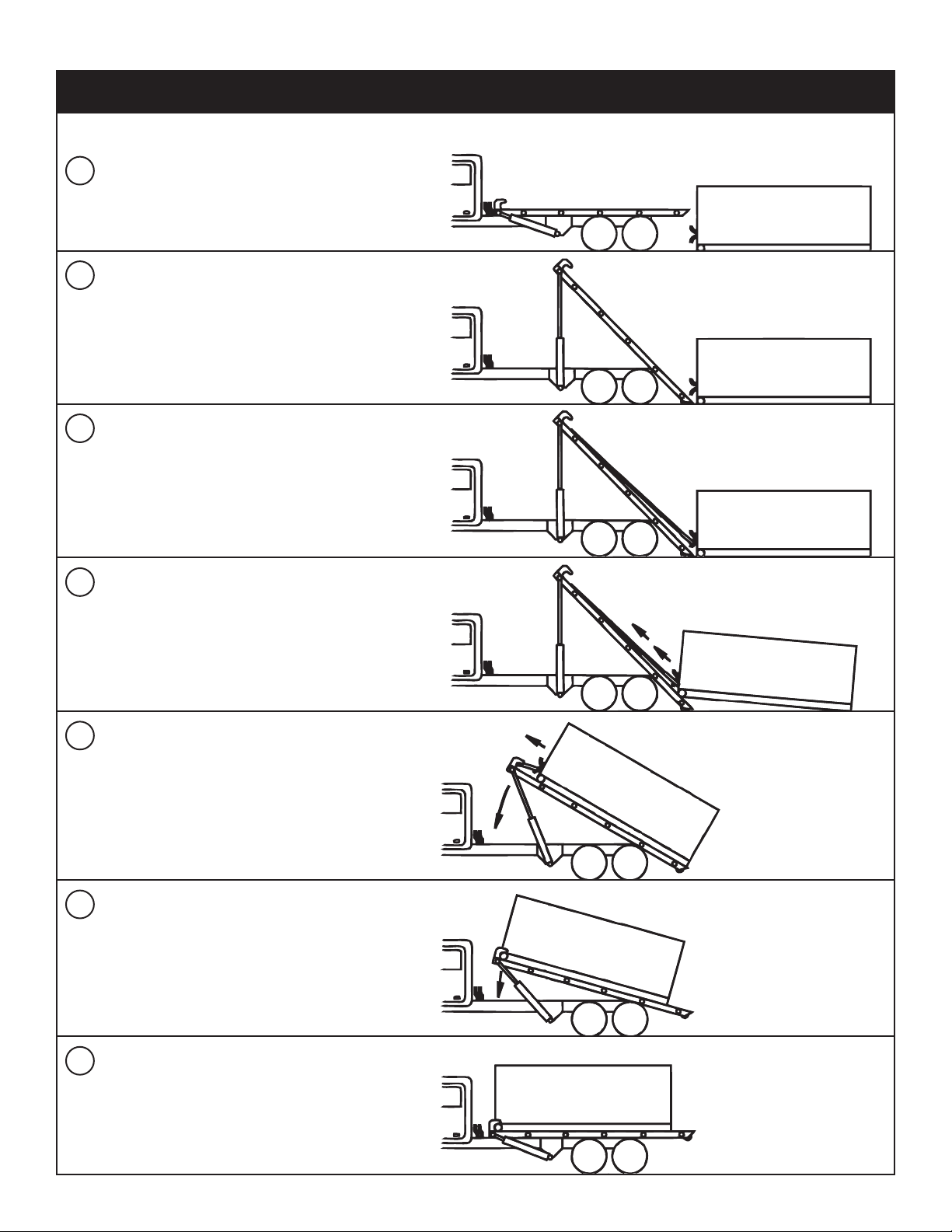
Back the truck up to the container
to be loaded and align the hoist rails
with the container long sills.
1
Engage the PTO and raise the hoist
until the rear roller is on the ground.
Set the parking brakes and retract
the reeving cylinders to connect the
cable to the container.
Release the parking brake and allow
the truck to roll under the container.
Extend the reeving cylinders to pull
the container onto the hoist. The
container long sills must be kept on
the hoist rollers.
Once the center of gravity of the
container is in front of the rear hinge,
the hoist can be lowered until the
front is just above the top of the
truck cab.
Continue pulling the container
forward until it is securely locked into
the front stops. Caution: Rear
hold-down devices are required
on the hoist and the containers.
Lower the hoist to the full-down
position and disengage the PTO.
2
3
4
5
6
7
Operation
Loading Operation
Page 12
Stellar Cable Hoist Owner’s Manual
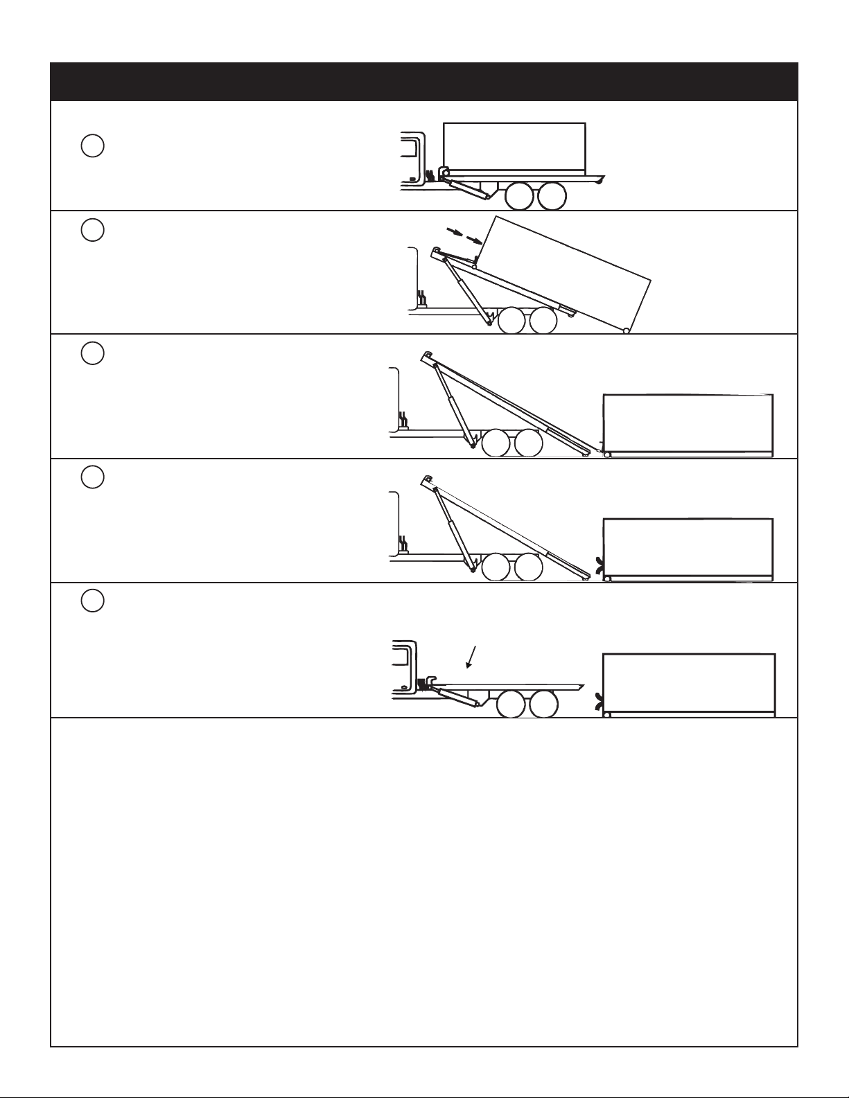
Back the truck up in front of where the
container is to be spotted. Allow room
for the container to roll-off of the hoist.
1
Raise the hoist and retract the
reeving cylinders. Allow gravity to
pull the container to the ground.
Once the rear rollers are on the
ground, allow the truck to roll out
from under the container.
Once the container is on the ground,
lock the truck brakes and disconnect
the cable and secure it to the hoist.
Lower the hoist to the full down position.
Pull away from the container.
Disengage the PTO.
2
3
4
5
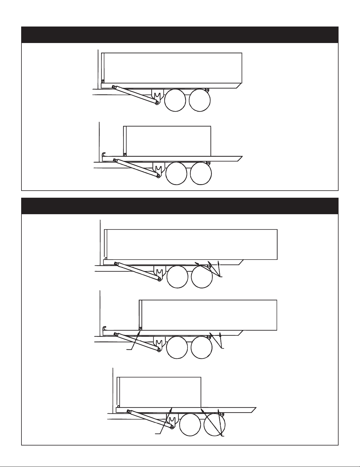
Unloading Operation - O.R. and I.O. Models
Page 13
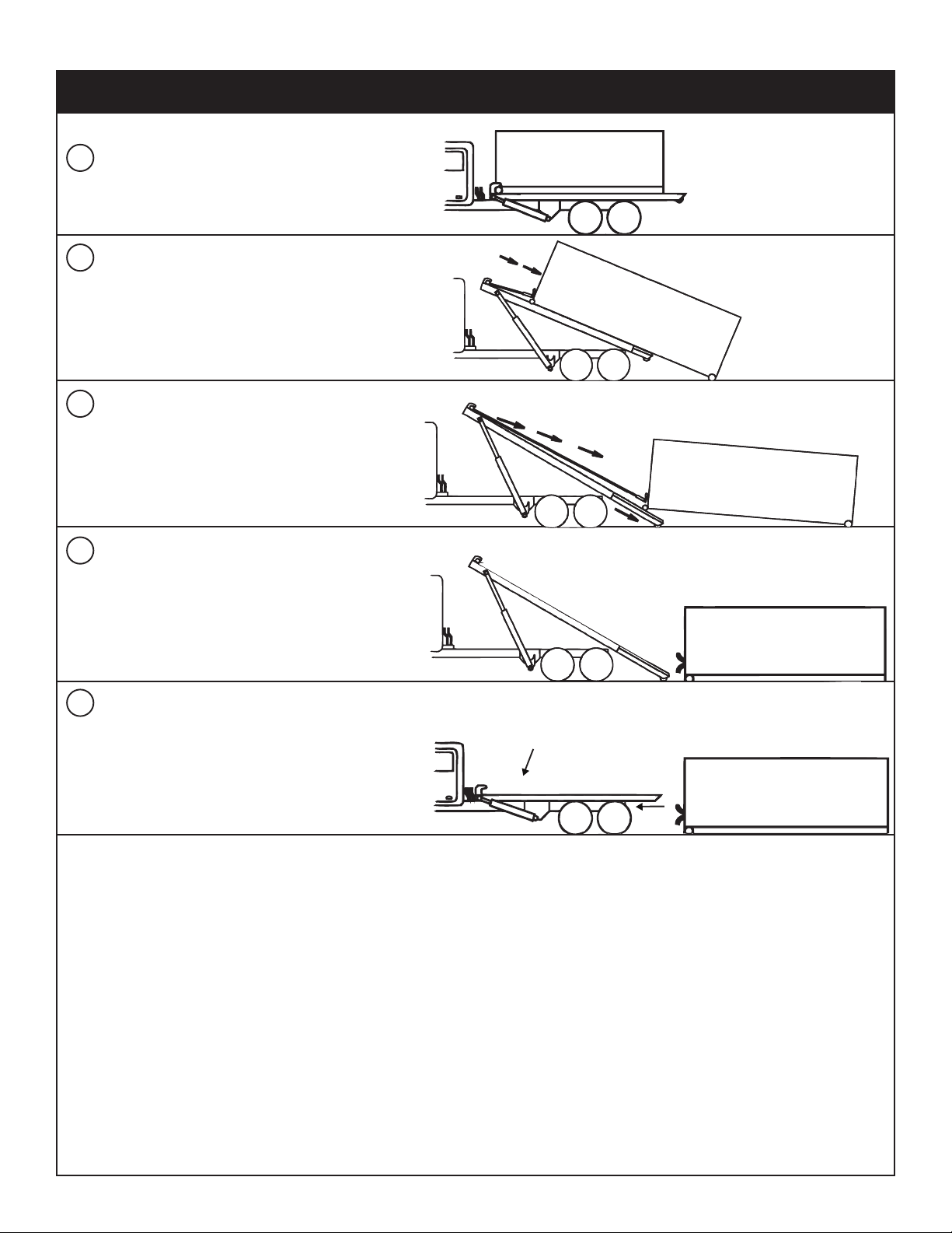
Operation
Back the truck up in front of where the
container is to be spotted. Allow room
for the container to roll-off of the hoist.
1
Raise the hoist and retract the
reeving cylinders. Allow gravity to
pull the container to the ground.
Once the rear rollers are on the
ground, allow the truck to roll out
from under the container.
Alternate extending the cable and
the tail until the container is on the
ground.
Lock the truck brakes and disconnect
the cable and secure it to the hoist.
Lower the hoist and retract the tail
section. Disengage the PTO before
driving away.
2
3
4
5
Unloading Operation - Extendable Tail Models
Page 14
Stellar Cable Hoist Owner’s Manual
Correct Container Position
Correct Position
For Short Container
Note: Removable front stops must
be used and rear hold downs must
match on container and roll-off
hoist.
The Container is Too Long
Load Center is Too Far to the Rear
Front Axle May Be Too Light
Front Axle May Be
Overloaded
Frame may crack or bend.
Frame may crack or bend.
Frame may crack or bend.
Frame may crack or bend.
Frame may crack or bend.
Correct Roll-Off Container Loads
Unsafe Roll-Off Container Loads
Page 15
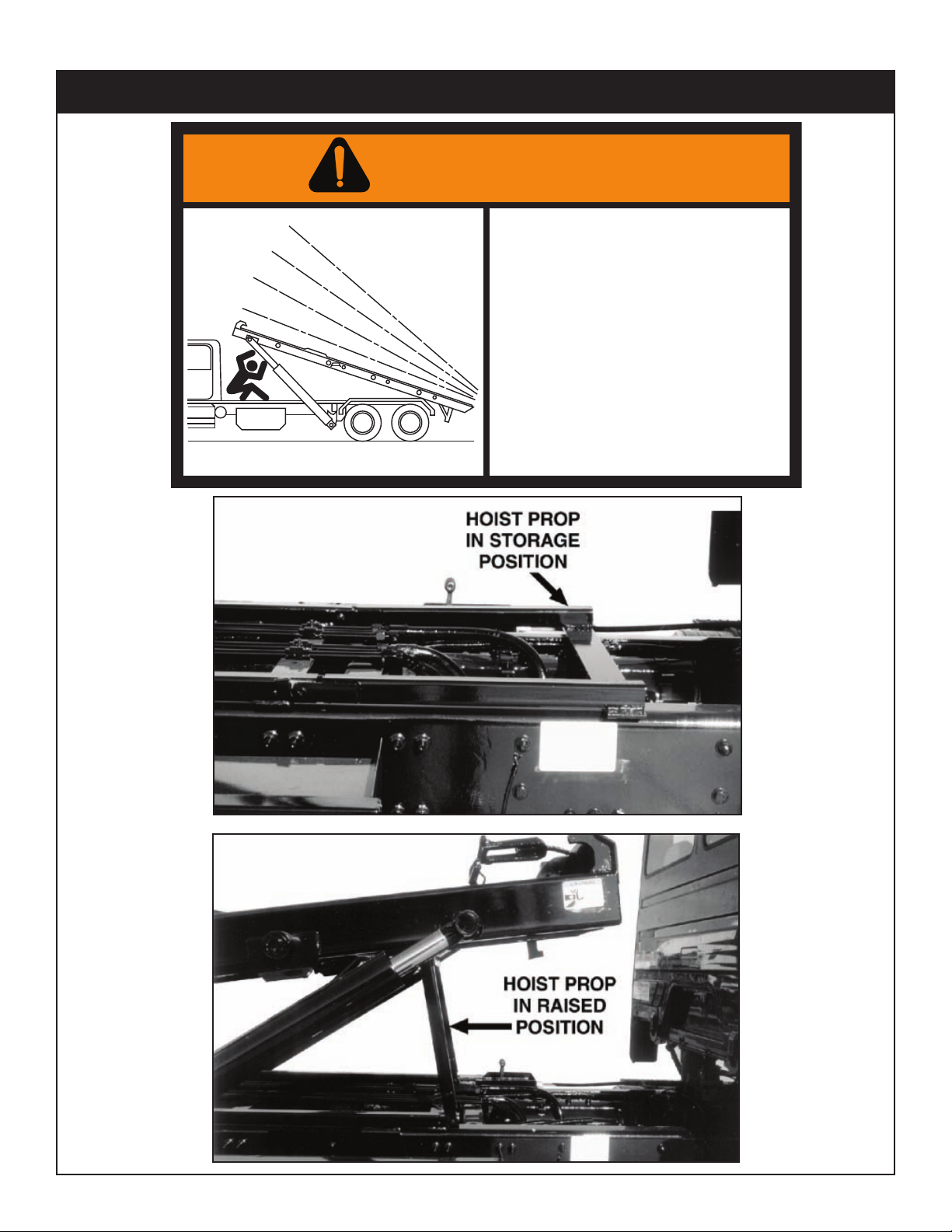
Hoist Prop Operation
WARNING
BEFORE WORKING AROUND A
RAISED HOIST, THE HOIST
MUST BE SUPPORTED BY THE
HOIST PROP.
(SEE HOIST PROP OPERATIN G
INSTRUCTIONS)
FAILURE TO DO SO COULD RESULT IN
SERIOUS INJURY OR DEATH.
IF THE HOIST PROPS CANNOT BE
USED, CONSULT THE MAINTENANCE
SECTION OF THE OPERATION MANUAL
FOR THE PROPER PRECAUTIONS.
45553
Operation
Page 16

Stellar Cable Hoist Owner’s Manual
Page 17

Chapter 3 - Maintenance
Maintenance
Please read the following before performing any
maintenance on the Cable Hoist.
1. Only authorized service personnel are to perform
maintenance on the Cable Hoist.
2. Disengage the PTO before any service or repair
is performed.
3. Do not disconnect hydraulic hoses while there is
still pressure in those components.
4. Before disconnecting hydraulic components,
shut off the engine, release any air pressure on
the hydraulic reservoir, and move control levers
repeatedly through their operating positions to
relieve all pressures.
5. Keep the Cable Hoist clean and free from
grease build-up, oil and dirt to prevent slippery
conditions.
6. Perform all safety and maintenance checks
before each period of use.
7. Replace parts with Stellar Industries, Inc.
approved parts only.
8. Immediately repair or have repaired any components found to be inadequate.
Maintenance Procedures
1. Position the Cable Hoist where it will be out of
the way of other operations or vehicles in the
area.
2. Place all controls in the off position and secure
operating features from inadvertent motion.
3. Relieve hydraulic oil pressure from all hydraulic
circuits before loosening or removing hydraulic
components.
4. Label or tag parts when disassembling.
Periodic Inspection
Periodic Inspection should occur while the Cable
Hoist is in use. For the duration of the usage,
inspect the Cable Hoist for all of the following:
1. Loose bolts and fasteners.
2. All pins, bushings, shafts, and gears for wear,
cracks, or distortion to include all pivot points,
and bushings.
3. Hydraulic systems for proper operating pressure.
4. Main frame mount bolts.
5. Cylinders for:
A. Damaged rods.
B. Dented barrels.
C. Drift from oil leaking internally.
D. Leaks at rod seals or holding valves.
6. PTO and hydraulic pump(s) for leaks.
7. Hydraulic hose and tubing for evidence of damage such as blistering, crushing, or abrasion.
8. Presence of this owner’s manual.
Daily Inspection
Daily Inspection should occur each day before the
Cable Hoist is put into use. Each day, inspect the
Cable Hoist for all of the following:
1. Hydraulic oil level.
2. Loose parts or damage to structures or weld.
3. Cylinder movement due to leakage.
4. Hoses for evidence of oil leaks.
5. Controls for malfunction or adjustment.
6. Parking brake operation.
7. All securing hardware such as cotter pins, snap
rings, hairpins, and pin keepers for proper installation.
8. All safety covers for proper installation.
9. Cylinder holding valves for proper operation.
10. Equipment for missing, illegible, or defaced
operating decals and safety signs.
11. Inspect the wire rope for fraying or other wear.
Monthly Inspection
Monthly Inspection should occur at the beginning
of every work month. Each month, inspect the
Cable Hoist for all of the following:
1. Frame bolt tightness - turn barrel nuts and mount-
ing bolts during the first month of operation on
new machines and then quarterly thereafter.
2. Cylinders and valves for leaks.
3. Lubrication.
4. Structural weldments for bends, cracks, or breaks.
5. All pins and keepers for proper installation.
6. All control, safety, and capacity placards for
readability and secure attachment.
7. Inspect all electrical wires and connections for
worn, cut, or deteriorated insulation and bare
wire. Replace or repair wires as required.
8. Lubrication of all points requiring lubrication.
General Service
The following general suggestions should be helpful
in analyzing and servicing your Cable Hoist. Using
the following systematic approach should be helpful in finding and fixing problems:
1. Determine the problem.
2. List and record possible causes.
3. Devise checks.
4. Conduct checks in a logical order to determine
the cause.
5. Consider the remaining service life of compo-
nents against the cost of parts and labor necessary to replace them.
6. Make the necessary repair.
7. Recheck to ensure that nothing has been over-
looked.
8. Functionally test the new part in its system.
Page 18
Stellar Cable Hoist Owner’s Manual
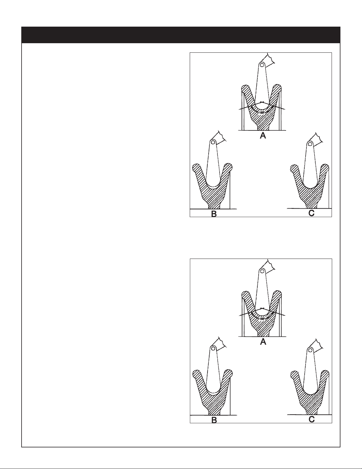
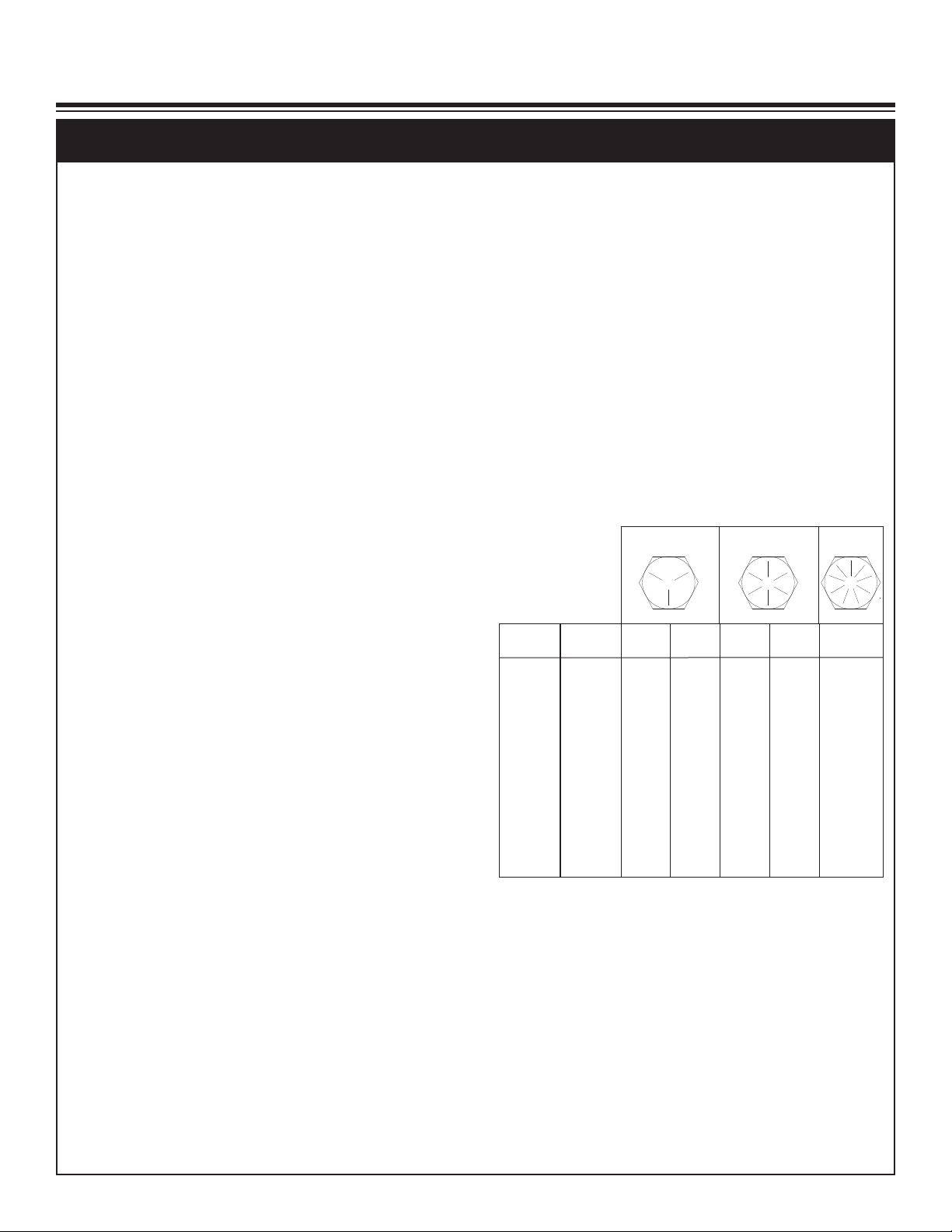
Cross-sections illustrating three sheeve-groove conditions.
A is correct, B is too tight, and C is too loose.
Cross-sections illustrating three sheeve-groove conditions.
A is correct, B is too tight, and C is too loose.
Inspection of Sheaves
Under normal conditions, machines should
receive periodic inspections, and their overall condition recorded. Such inspections
usually include the sheaves, and any other
parts that may come into contact with the
wire rope and subject it to wear. As an
additional precaution, rope related working
parts, particularly in the area described
below, should be re-inspected prior to the
installation of a new cable.
The very first item to be checked when
examining the sheaves is the condition of
the grooves. To check the size, contour and
amount of wear, a groove gage is used. As
shown in the illustration to the right of this
paragraph, the gage should contact the
groove for about 150º of arc.
Two types of groove gages are in general
use and it is important to not e which of these
is being used. The two differ by their respective percentage over nominal.
For new or re-machine grooves, the groove
gage is nominal plus the full oversize percentage. The gage carried by most wire
rope representatives today is used for worn
grooves and is made nominal plus 1/2 the
oversize percentage.
The latter gage is intended to act as a sort
of “no-go” gage. Any sheave with a groove
smaller than this must be replaced or, in all
likelihood, the existing rope will be damaged.
Experience has clearly demonstrated that
the service life of the wire rope will be materially increased by strict adherence to these
standards.
Page 19
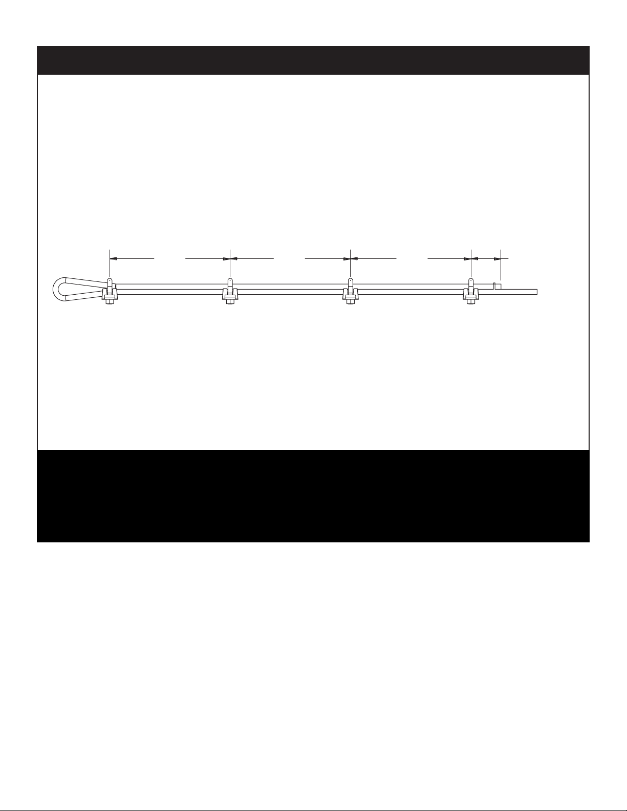
Cable Replacement
5.0020.0020.00 20.00
B
C
DA
CABLE CLAMP DETAIL
CLAMP INSTRUCTIONS
INSTALL CLAMP "A" TORQUE NUTS TO 225 FT-LBS.
1.
INSTALL CLAMP "B" SNUG NUTS ON CABLE.
2.
INSTALL CLAMPS "C" & "D" AS SHOWN SNUG NUTS.
3.
APPLY TENSION TO CABLE.
4.
TORQUE NUTS ON "B", "C" & "D" TO 225 FT-LBS.
5.
CLAMP NUTS MUST FACE DOWN.6.
Important: Standard replacement cable must be 7/8” diameter 6 x 37 extra improved plow steel
with steel core (6 x 37 EXIWRC) with a 4.00” swaged button x 75’ (174” & 182” CT, or) 77 feet (194”
CT) in length.
1. Remove the cable clamps and discard the old cable.
2. Inspect all the sheaves (See Inspection of Sheaves on page 12).
3. Install cable end onto cable. Thread cable through sheaves and guides, etc. Loop cable
through cable anchor and install clamps following the diagram below. Torque all bolts evenly
to 225 ft. lbs.
Maintenance
Cleanliness
An important item in preserving the long life of the cable hoist is keeping
dirt, grime, and corrosive material out of the working parts. Thoroughly
wash and grease the cable hoist periodically.
Page 20

Stellar Cable Hoist Owner’s Manual
Choice Lubricants for DX Bearings
Greases Recommended
Type of Grease Description
Premium Quality
Multi-Purpose
Multi-Purpose Calcium Based, for General Automotive and Industrial Use
Anti-Friction Bearing Calcium Based with EP Additives
Extreme Pressure (EP) Lithium Based with EP Additives
High Temperature Modified Sodium Based, High Drop Point
Transmission Semi-Fluid, Calcium Based
Molybdenum Filled Lithium Based with 2% Molybdenum Disulfide
Graphite Filled Sodium Based with 2% Graphite
Block Grease Sodium Based Solid Grease
White Grease Aluminum Complex Based with Anti-Oxidant & Rust
Silicone Lithium Based with Silicone Oil Lubricant
Stabilized, Anti-Oxidant Lithium Base
Lithium Base with 3% Molybdenum Disulfide
High Drop Point
Calcium Grease, Water Stabilized, High Drop Point
Lithium Based
Sodium Based
Calcium Based with EP Additives
Inhibitors & Zinc Oxide Additives
Greases Not Recommended
Type of Grease Description
Cup Grease Light Service Calcium or Sodium Based Grease
Graphite Filled Greases with More than 10% Graphite
Molybdenum Filled Greases with More than 10% Molybdenum Disulfide
Fluorocarbon Low Molecular Weight Chlorofluoroethylene Polymer
with Inert Thickeners
White Grease Calcium Based, Zinc Oxide Filled
Page 21

Chassis C.T.: See chart on next page.
Frame Width: 35-1/2”
Minimum GVWR: 18,000 lbs. Front, 44,000 lbs. Rear
Frame Height: 43”
Sub-Frame: Full length 2 x 4 Tube
Load Rating: 60,000 lbs., 75,000 lbs.
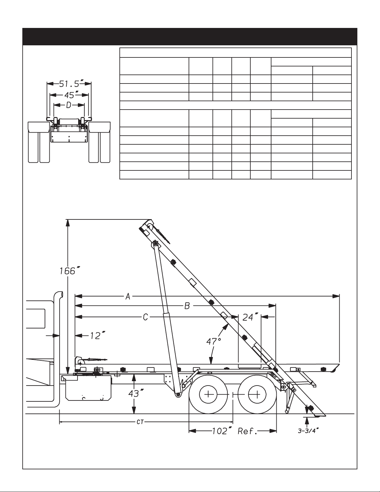
Dump Angle: 47º
Operating Pressure: 1,850 PSI (60,000 lbs), 2,150 PSI (75,000 lbs)
Gear Pump: 35 GPM @ 1,500 RPM
Operation: Inside Cab Cable Controls Standard
Weight: 6,400 lbs. - 7,400 lbs.
Cylinders: Twin Double Acting
6 x 72 Lift Model SI-60/75
7 x 80 Reeving Model SI-60/75
7 x 90 Reeving Model SI-60/75
Low Pressure Hydraulic System
Gear Driven Hydraulic Pump
Large 3” Rear Pivot Pin
Hold-down compatible with ANSI Z245.6 Type “U” Containers
Chapter 4 - Specifications
Specifications
Page 22
Stellar Cable Hoist Owner’s Manual
*Autotarper installation requires 12” of unobstructed space behind the truck cab.
Specifications Chart
Models A B C D
CT (Cab to Trunnion)
w/o Autotarper w/ Autotarper
SI-60-174 OR/IO 281” 210” 174” 35.5” 174” 180”
SI-60-182 OR/IO 289” 218” 174” 35.5” 182” 188”
SI-60-194 OR/IO 301” 230” 186” 35.5” 194” 200”
Extended Tail Models A B C D
CT (Cab to Trunnion)
w/o Autotarper w/ Autotarper
SI-60-174 ORX 237” 210” 174” 35.5” 174” 180”
SI-60-182 ORX 245” 218” 174” 35.5” 182” 188”
SI-60-194 ORX 257” 230” 186” 35.5” 194” 200”
SI-60-174 IOX 278.5” 210” 174” 35.5” 174” 180”
SI-60-182 IOX 286.5” 218” 174” 35.5” 182” 188”
SI-60-194 IOX 298.5” 230” 186” 35.5” 194” 200”
*
Cable Hoist Dimensions
Page 23
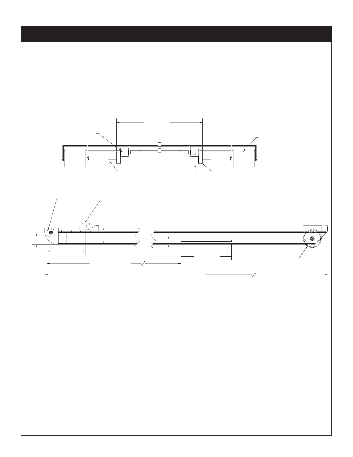
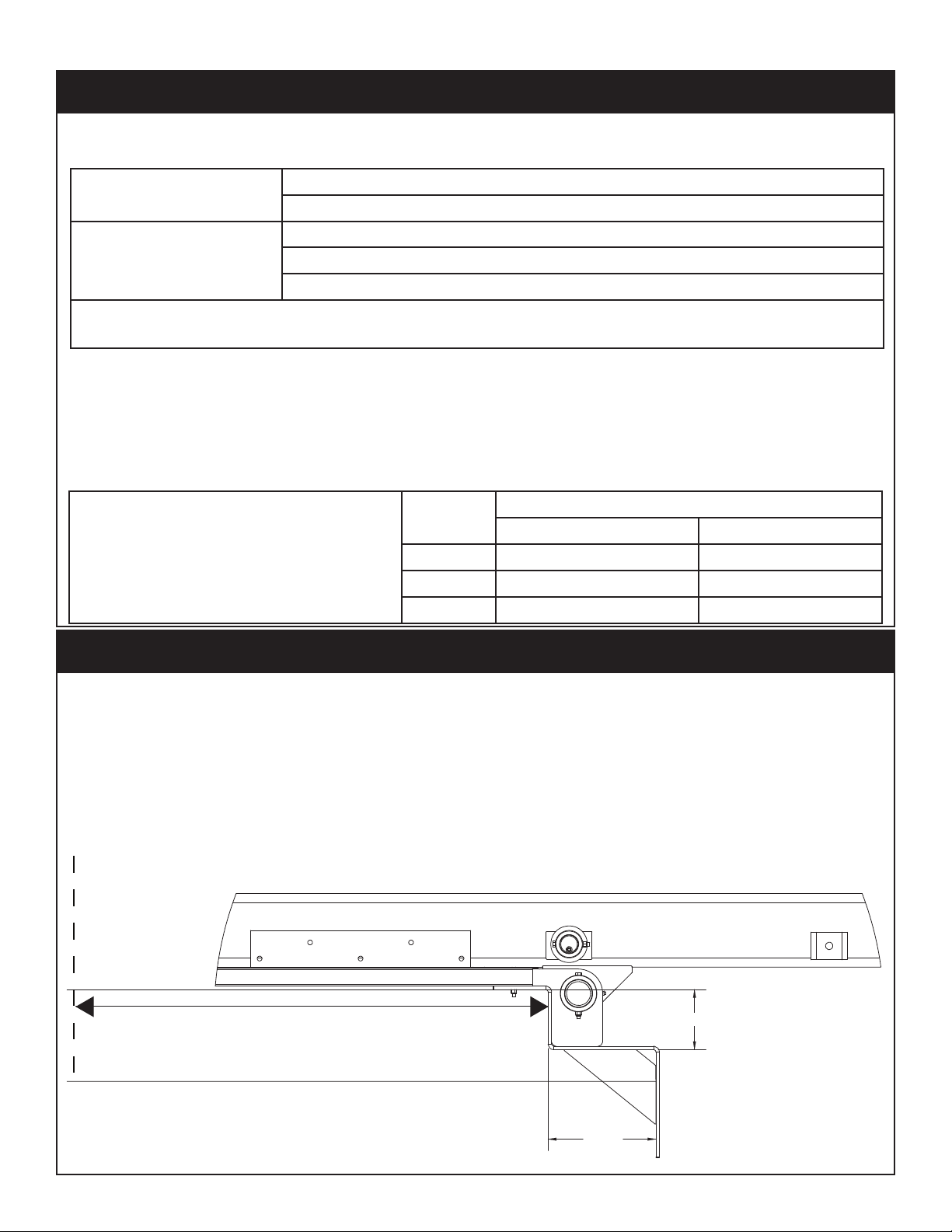
Container Subframe
PICKUP HOOK
SIDE VIEW
LEAD-IN-ROLLER
GROUND WHEEL
MIN. 6.00
MAX. 10.50
18.50MIN.
*SEE NOTE*
MAX. 24.00
MAX. 2.13
MAX. 3.63
MIN. 3.38
193.00
*LONG RAIL LENGTH*
TYPICAL REAR
GROUND WHEEL
GUIDE ROLLER
HOLDDOWN
2" X 6" STANDARD
STRUCTURAL TUBING
MAX. 3.63
MIN. 3.38
MAX. 41.00
FRONT OF LEAD-IN-ROLLER TO THE FRONT OF THE HOLDDOWN.
IF LONG RAIL LENGTH IS GREATER THAN OR EQUAL TO 18FT. AND LESS THAN
24FT, REAR HOLDDOWN DIMENSION IS 193.00 IN. PLUS 1 IN. MINUS 0 IN. FROM
FRONT VIEW
*NOTE*
IF LONG RAIL LENGTH IS GREATER THAN OR EQUAL TO 12FT. AND LESS THAN
18FT, REAR HOLDDOWN DIMENSION IS 147.50 IN. PLUS 1 IN. MINUS 0 IN. FROM
FRONT OF LEAD-IN-ROLLER TO THE FRONT OF THE HOLDDOWN.
NOTE:
ALL DIMENSIONS ARE IN ACCORDANCE WITH
ANSI Z245.60 TYPE "U" CONTAINER REQUIREMENTS
Specifications
Page 24

Stellar Cable Hoist Owner’s Manual
Page 25
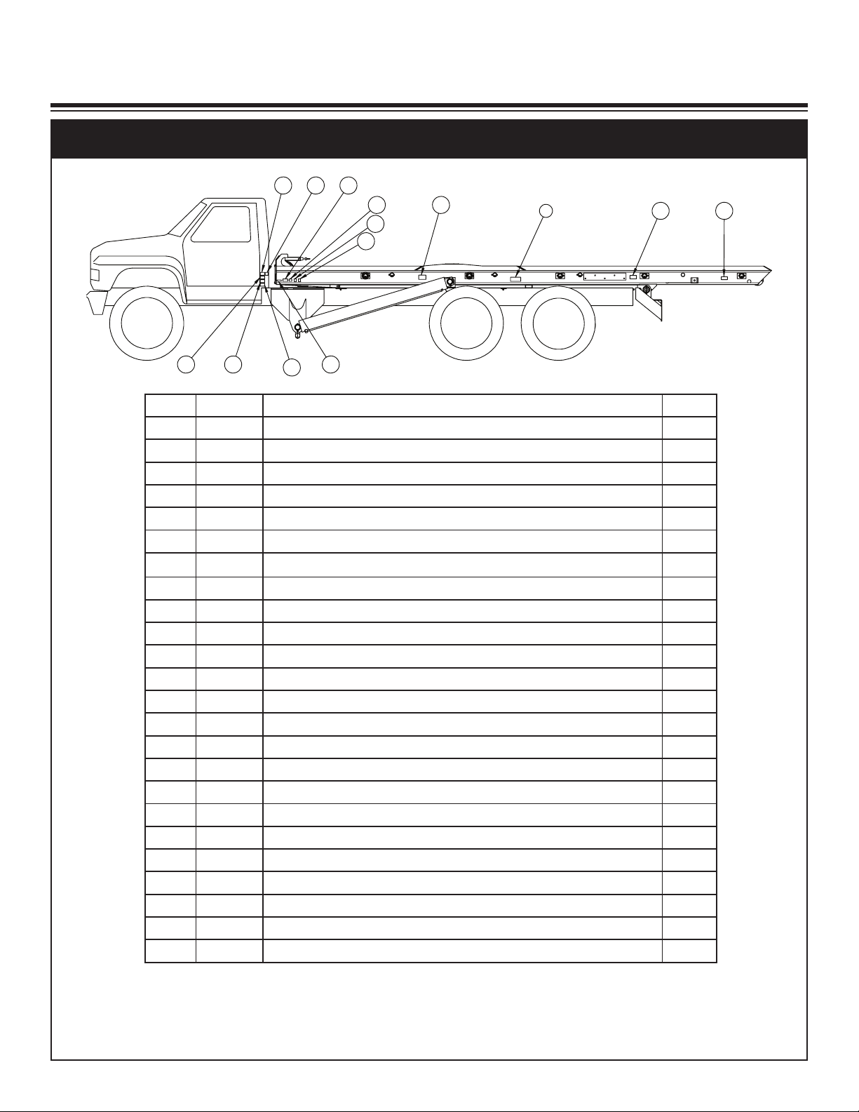
16
12
7
18
14
16
10
1117
1913
16
24
3
Item PN Description Qty.
1 45702 TAPE CONSPICUITY YELLOW 9.00 IN
a
2
2 45701 TAPE CONSPICUITY RED 9.00 IN
b
2
3 16094 DECAL STELLAR LOGO5.00X13.00REFLECT 2
4 46657 DECAL TAIL 2
5 45981 DECAL WINCH 2
6 46071 DECAL HOIST 2
7 45553 DECAL WARNING RAISED HOIST 2
8 45807 VALVE PLATE
d
c
c
c
c
f
f
e
e
e
e
1
9 45691 DECAL HOIST INSTRUCTIONS 1
10 45692 DECAL WARNING CONTAINER 2
11 45693 DECAL CAUTION OPERATION 1
12 45694 DECAL PROP INSTRUCTIONS 2
13 45695 DECAL WARNING UNEVEN GROUND 2
14 45696 DECAL DANGER POWER LINES HOIST 2
15 45697 DECAL CAUTION PTO SPEED 1
16 25627 DECAL CRUSH POINT 6
17 45698 DECAL WARNING CABLE 2
18 45557 DECAL DANGER STAND CLEAR 2
19 C5942 PLATE SERIAL # STELLAR TRUCKS 1
20 45699 DECAL ICC BUMPER REQUIREMENT 1
21 45906 DECAL HOIST UP 1
22 49546 TAPE CONSPICUITY RED/WHITE 38.00FT 1
23 49547 TAPE CONSPICUITY WHITE 4.00FT 1
24 35234 DECAL STELLAR MADE IN THE USA 1
a
ON FRONT OF REAR FENDER (NOT SHOWN)
b
ON BACK OF REAR FENDER (NOT SHOWN)
c
IN CAB (NOT SHOWN)
d
ON TOP OF HYD. RSRVR (NOT SHOWN)
e
QTY 1 IN CAB (NOT SHOWN)
f
SEE PAGE 38 FOR PLACEMENT (NOT SHOWN)
Chapter 5 - Decals
Decal Kit Placement
Decals
Note: See page 41 for Reflective Tape Placement.
Page 26
Stellar Cable Hoist Owner’s Manual
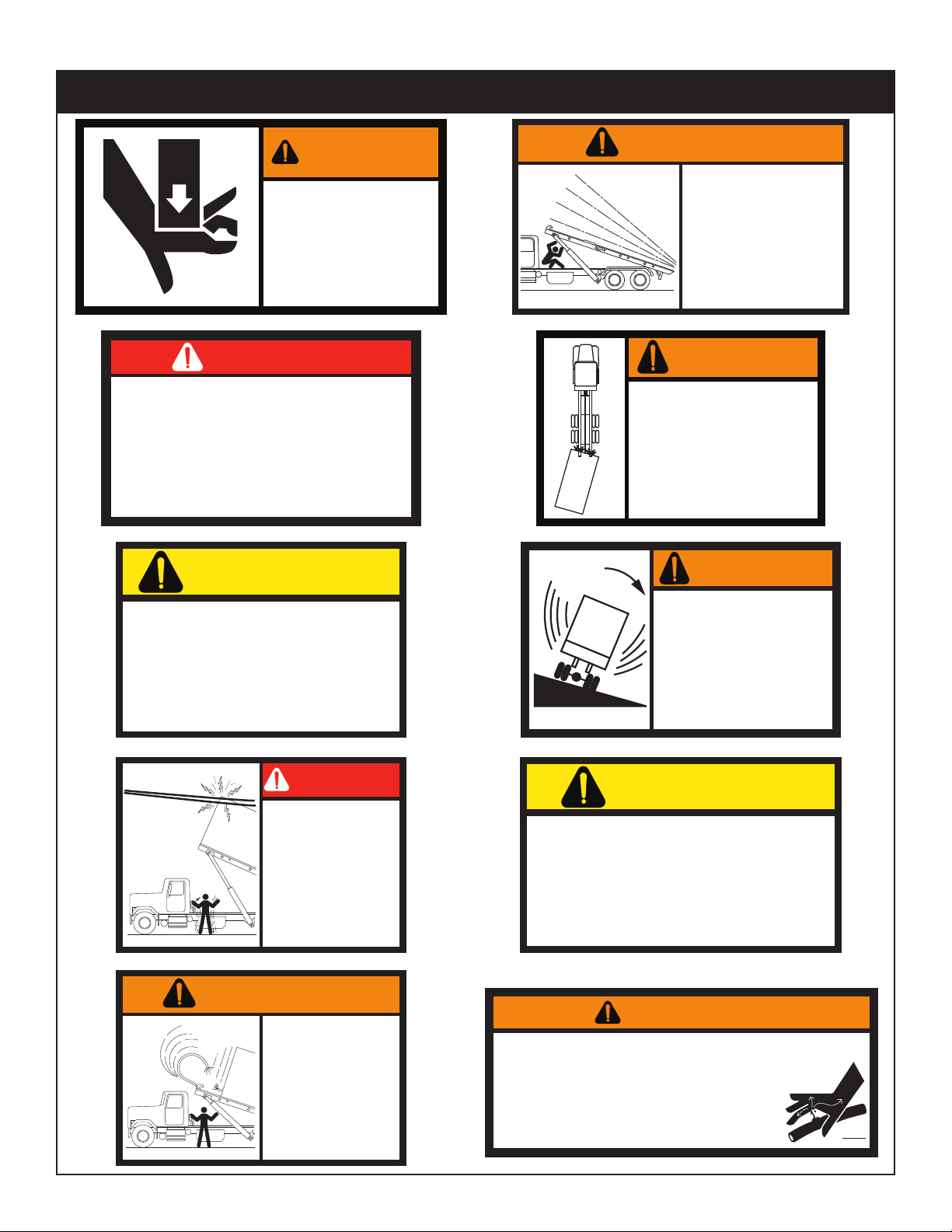
WARNING
CRUSHING HAZARD
Moving parts can
crush and cut.
Keep hands and
arms clear.
25627
DANGER
STAN D CLEAR
WHEN THIS UNIT IS IN OPERATION!
FAILURE TO DO SO COULD RESULT IN
SERIOUS PERSONAL INJURY.
45557
CAUTION
DO NOT ATT EMPT TO OPERATE
THIS EQUIPMENT WITHOUT PROPER TRAINING.
PERSONAL INJU RY AND EQU IPMENT DAMAGE
CAN OCCUR IF THIS EQUIPMENT IS USED IMPROPERLY.
REA D AN D UNDERSTAND THE OPERAT ION MANUAL.
45693
DANGER
BE AWARE OF POWER
LINES AND OVERHEAD
OBSTRUCTIONS.
CONTACT BY THE HOIST OR
CONTAINER COULD CAUSE
SERIOUS INJURY OR DEATH
TO THE OPERATOR AND
BYSTAN DERS.
45696
WARNING
45698
RAISE HOIST ABOVE THE TOP
OF THE TRUCK CAB BEFORE
LOADING OR UNLOADING A
CONTAI NER, UNLESS A CAB
GUARD IS INSTALLED.
CABLE FAILURE COULD RESULT
IN SERIOUS PERSONAL INJURY
AND EQUIPMENT DAMAGE.
WARNING
BEFORE WORKING AROUND A
RAISED HOIST, THE HOIST
MUST BE SUPPORTED BY THE
HOIST PROP.
(SEE HOIST PROP OPERATI NG
INSTRUCTIONS)
FAILURE TO DO SO COULD RESULT IN
SERIOUS INJURY OR DEATH.
IF THE HOIST PROPS CANNOT BE
USED, CONSULT THE MAINTENANCE
SECTION OF THE OPERATION MANUAL
FOR THE PROPER PRECAUTIONS.
45553
DO NOT ATTEMPT TO LOAD A CONTAINER
UNLESS THE HOIST AND CONTAINER ARE
CORRECTLY ALIGNED.
KEEP THE CONTAINER RAILS SAFELY
ENGAGED WITH THE HOIST RAILS AND
ROLLERS.
FAILURE TO DO SO COULD CAUSE THE
CONTAINER TO SLIDE OFF THE SIDE OF
THE HOIST OR JAM ON THE RAILS.
WARNING
45692
WARNING
DO NOT LOAD, UNLOAD OR
DUMP CONTAINER ON
UNEVEN GROUND.
A LOADED CONTAINER CREATES A TOP
HEAVY LOAD. USE CAUTION WHEN
DRIVING ON UNEVEN GROUND AND
TURNING CORNERS.
SERIOUS PERSONAL INJURY AND
EQUIPMENT DAMAGE COULD RESULT.
45695
CAUTION
45697
DO NOT EXCEED 1600 ENGINE
RPM WHEN OPERATING
POWER TAKE OFF!
Escaping fluid under pressure can penetrate the skin causing serious injury
or death. Relieve pressure before disconnecting hydraulic lines, tighten all
connections before applying pressure, and inspect all lines before
each use. See "Safety" section in operation manual for additional
information.
If an accident occurs, see a doctor immediately. Any fluid
injected into the skin must be surgically removed within a
few hours or gangrene may result.
45726
74-276
WARNING
Safety Decals of Note
Page 27
Chapter 6 - Installation
General Install Guidelines
Installation
Cable Hoist Mounting and Assembly
Study names and locations of the parts and
familiarize yourself with the Cable Hoist
before starting the assembly . Reading the
step-by-step instructions that follow will be
helpful.
Safety
Read all of the safety notations in the
assembly instructions for your protection.
Accidents can be prevented by recognizing the cause of an accident before it can
happen.
Assembly
Select an area for assembly that will be
large enough to accommodate the completed unit. The surface of the work area
should be as level as possible. Use the
proper hand tools to ensure proper bolt
tightness. Refer to the chart below for the
recommended torque values for different
sizes of bolts.
Recommended Torque Values in Foot
Pounds
For SAE GRADE 2 and GRADE 5 coarse
thread cap screws and bolts shown are
suggested maximum for fasteners, carrying
only the residue oil of the manufacturer.
Proper Bolt Use
Do not use these values if a different torque
value or tightening procedure is given for a
specific application. Torque values listed
are for general use only. Check tightness of
fasteners periodically.
Sheer bolts are designed to fail under predetermined loads. Always replace shear
bolts with identical grade.
Fasteners should be replaced with the
same or higher grade. If higher grade fas-
teners are used, these should only be tightened to the strength of the original.
Tighten plastic insert or crimped steel-type
lock nuts to approximately 110 percent of
the dry torque values shown in the chart
below, applied to the nut, not to the bolt
head. Tighten toothed or serrated-type
lock nuts to the full torque value.
Note: “Lubricated” means coated with a
lubricant such as engine oil, or fasteners
with phosphate and oil coatings. “Dry”
means plain or zinc plated without lubrication. Tighten lubricated bolts to approximately 80% of dry bolts.
Grade 8 Grade 9
Plated
Plain
25
44
70
105
155
220
375
605
910
(Ft-Lb)
18
33
52
80
115
160
280
455
680
965
1360
1780
2370
(Ft-Lb)
1290
1815
2380
3160
Plated
(Ft-Lb)
22
39
63
96
139
192
340
549
823
1167
1646
2158
2865
Size
(DIA-TPI)
5/16-18
3/8-16
7/16-14
1/2-13
9/16-12
5/8-11
3/4-10
7/8-9
1-8
1 1/8-7
1 1/4-7
1 3/8-6
1 1/2-6
Bolt DIA
(Inches)
0.3125
0.3750
0.4375
0.5000
0.5625
0.6250
0.7500
0.8750
1.000
1.1250
1.2500
1.3750
1.500
Grade 5
Plain
(Ft-Lb)
17
31
49
75
110
150
265
395
590
795
1120
1470
1950
Plated
(Ft-Lb)
13
23
37
57
82
115
200
295
445
595
840
1100
1460
Model Number
Know the model number of the Stellar
Cable Hoist being mounted. Use this model
number whenever referring to the assembly
or parts listing pages. The number is
stamped on the name plate which is located on the front frame member.
Right and Left sides can be established by
standing behind the truck frame and looking towards the front, or the direction of
travel.
Page 28
Stellar Cable Hoist Owner’s Manual
Minimum Axle Rating:
Front: 18,000 lbs.
Rear: 44,000 lbs. with walking beam type suspension
Frame Strength:
Total RBM per frame rail = 2,400,000 in-lbs. (both channels)
Section Modulus (minimum) = 32 in
3
for 36,000 PSI steel
Section Modulus (minimum) = 24 in
3
for 55,000 PSI steel
Important: If your truck chassis height exceeds the 45” dimension, or tire dimension is
greater than 102”, the O.R.X. or I.O.X. hoist should be considered.
Relocate the rear axles as required.
Stellar Autotarper must have 10”
to 12” unobstructed space behind
cab for installation.
Model
Cab to Trunnion
w/o Tarper With Tarper
SI60-174 174 Inches 180 Inches
SI60-182 182 Inches 188 Inches
SI60-194 194 Inches 200 Inches
6-9/16
FRAME RAIL
11-3/4
Cab Boundary
Refer to dimensional drawings on the following pages
for placement of step cut in relation to cab boundary.
Truck Chassis Specifications
See the illustrations on pages 15-17 at the front of this manual for specific details.
1. Thoroughly check the truck requirements to ensure proper clearance and frame
strength before mounting the hoist. Note: The rear cab boundary is the rearmost
unremovable protrusion behind the cab and above the chassis frame.
2. The CT, from the rear of the cab boundary to the center of the walking beam suspension, is shown in the table below:
Step 1: Truck Frame Cut-Off
Measure and mark the truck frame as shown below. Use the dimensional drawings on
the following pages to determine where to mark the first vertical cut on the frame rail.
Measure assembled hoist to be sure that adequate room is available behind truck cab;
between bumper and tires; and between fender and tires. This verifies that a measurement error has not been made either in the CT (Cab to Trunnion) or cut-off dimension.
After double checking your measurements, step-cut the truck frame as shown below.
Page 29
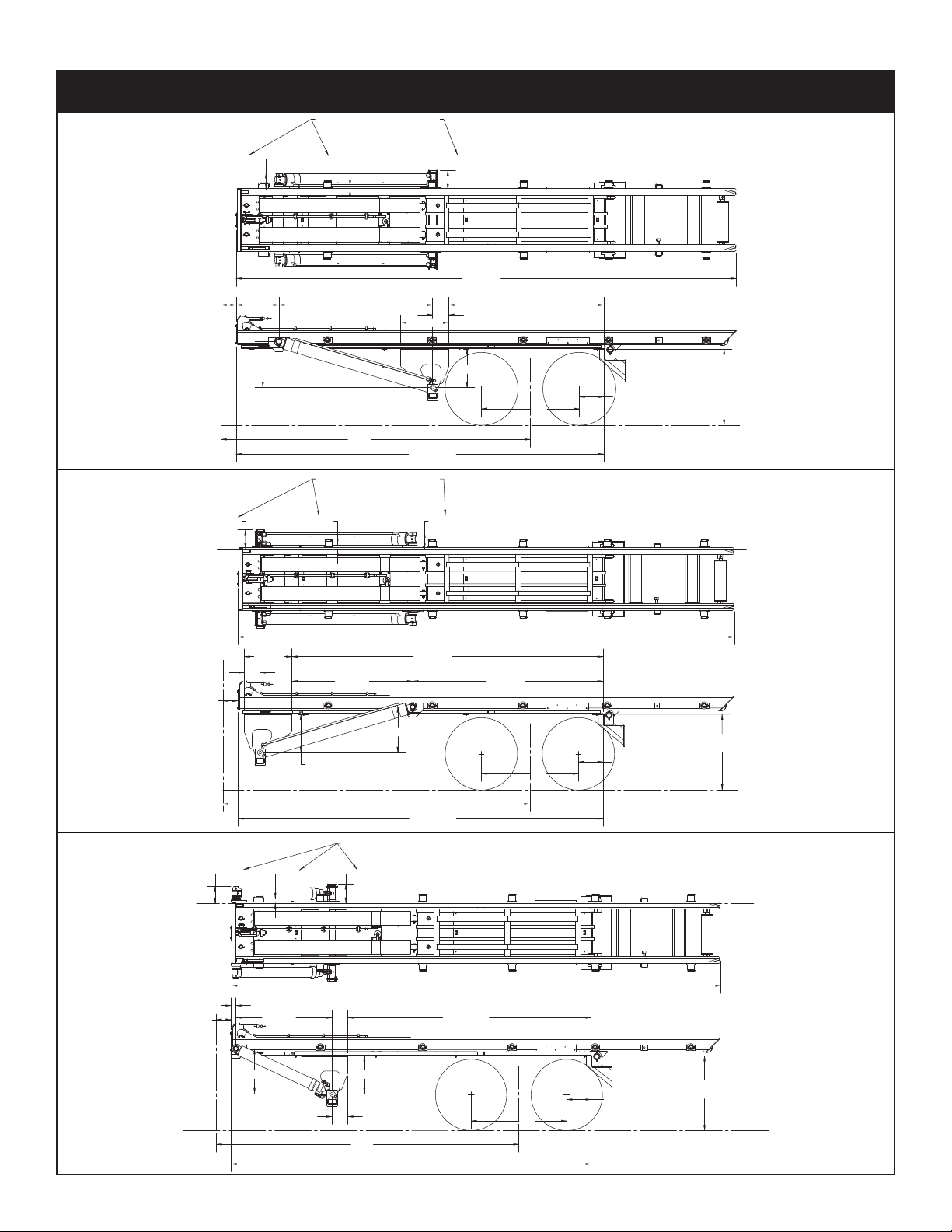
8 - 9/16
55
14
Rearmost Axle
To First Cut
43
Chassis Frame Height
174
C.T.
11
2 - 1/4
9 - 9/16
- 3/421
- 15/16
87
24
26 - 5/8
- 1/2
- 7/1686
9
206
25 - 13/16
281 - 1/4
Dimensions To Chassis Frame Rail
Forward Mount
Reverse Mount
Telescopic Mount
11 - 9/1692
- 1/4
8 - 9/16
55
14
Rearmost Axle
To First Cut
Chassis Frame Height
43
174
C.T.
Dimensions To Chassis Frame Rail
281 - 1/4
176
206 - 15/16
21 - 3/4
- 7/8107
68 - 7/8
9
26 - 5/8
- 3/4
25 - 13/16
112 - 9/169 - 9/16
8 - 9/16
C.T.
55
14
Rearmost Axle
to First Cut
174
43
Chassis Frame Height
Dimensions to Chassis Frame Rail
2 - 3/4
9
- 15/16139
- 3/421 - 13/1625
- 1/455
206 - 15/16
281 - 1/4
Dimensions: 174 Models
Installation
Page 30

Stellar Cable Hoist Owner’s Manual
Forward Mount
Reverse Mount
Telescopic Mount
8 - 9/16
182
C.T.
55
14
Rearmost Axle
to First Cut
43
Chassis Frame Height
9 - 9/16 2 - 1/4 11
21 - 3/4
32
87 - 1/2
- 5/8
9
26
- 1/286
- 13/1625
214 - 15/16
Dimensions to Chassis Frame Rail
289 - 1/4
8
- 9/16
43
Chassis Frame Height
55
14
Rearmost Axle
to First Cut
182
C.T.
11.00
9.56
2.22
- 5/8
- 3/4
86
- 1/2
26
107
9
214
- 7/8
- 15/16
- 3/4176
21
25 - 13/16
Dimensions to Chassis Frame Rail
289 - 1/4
9 - 9/16 112
- 9/16
6 - 7/16
43
Chassis Frame Height
55
14
Rearmost Axle
to First Cut
180
C.T.
289 - 3/8
Dimensions to Chassis Frame Rail
- 1/16
- 1/4
- 5/8
55
- 7/8
2
215
9
21
- 15/16
26
147
- 3/4
25 - 13/16
Dimensions: 182 Models
Page 31

Forward Mount
Reverse Mount
Telescopic Mount
9 - 9/16
2 - 1/4
11
8 - 9/16
43
Chassis Frame Height
Rearmost Axle
55
14
to First Cut
194
C.T.
Dimensions to Chassis Frame Rail
87
- 15/16
- 7/16
226
9
- 3/44421
86 - 1/2
25 - 13/16
301 - 1/4
11 2 - 1/4 9 - 9/16
8 - 9/16
43
Chassis Frame Height
55
14
Rearmost Axle
to First Cut
194
C.T.
301 - 1/4
Dimensions to Chassis Frame Rail
- 3/4
- 13/16
- 5/8
23
- 15/16
26
86 - 1/2
- 9/16
176
25
9
226
21 - 3/4
11
2 - 9/169 - 9/16
8 - 9/16
55
C.T.
194
14
Rearmost Axle
to First Cut
43
Chassis Frame Height
Dimensions to Chassis Frame Rail
301 - 1/4
- 13/16
148
26
55
- 3/4
21
226
- 15/16
25
9
- 3/16
- 5/852 - 1/8
Dimensions: 194 Models
Installation
Page 32

Stellar Cable Hoist Owner’s Manual
A
DETAIL A
SCALE 1 : 8
.38
(.25)
W=.38
TYP. (2)
.38
TYP. (2)
.38
6
.38
TYP. (2)
.38
.38
TYP. (2)
.38
TYP. (2)
1
.19
.19
TYP. (2)
.19
3
TYP. (2)
.19
3
TYP. (2)
ITEM
PART
DESCRIPTION
QTY.
1 45129
PLATE SIDE
1
Step 2: Mount Hoist
Note: Refer to the illustration on the previous pages.
A. Position the hoist sub-frame onto truck frame, aligning and squaring up with truck
frame, clamp and then heavily tack in place.
B. Continue to fully weld the hoist rear apron to the truck frame. Weld 100% 3/8” weld
both sides of truck frame to hoist sub-frame:
C. Weld the gussets onto the hoist apron:
Page 33

Installation
88.25±.13
DIMENSION WHEN INSTALLING.
ACTUAL RETRACTED DIMENSION IS 88"
Figure A
TRUCK FRAMETRUCK FRAME
TYPICAL BOLT HOLE PATTERN
MOUNTING KIT - BOLTED ON
11/16" DIAMETER DRILL
PN C5902
WASHER 0.63 SAE
FLAT YELLOW GR8
CAP SCR 0.63-11X2.50
HHGR8
PN C1026
PN 24868
NUT 0.63-11
HHGR8 NYLOC
0.25
TYP 2
0.25
TYP 4
0.25
TYP 2
Figure B
0.25
TYP. 4
0.19 1.00
TYP. 4
Step 3: Mount Lift Cylinders
A. Check frame for bolts, rivets, etc. and clearance required (Refer to the previous
pages) before placing the Lift Cylinder Weldment into place under the hoist sub-frame.
B. Install the cylinder weldment cross tube.
C. Install the Lift Cylinders and extend each cylinder rod 1/4”. Check the shaft to cylinder
dimension on both sides. Standard Lift Cylinders dimension should be 88 1/4” plus or
minus1/8”. Telescopic Cylinder dimension should be 61-1/4” plus or minus 1/8”. Be sure
to install proper cylinder shaft hardware so that Lift Cylinders do not interfere with truck
frame or bolts. The lift cylinders will precisely locate the lift cylinder weldments.
D. Clamp the Lift Cylinder Weldment in place and drill ten (10) 11/16” diameter holes as
per Figure B.
Page 34

Stellar Cable Hoist Owner’s Manual
FRONT
0.38 4-7.63
TYP 2
Figure C
Mount Lift Cylinders Continued...
E. Bolt the Lift Cylinder Weldment to the truck frame using the supplied hardware.
F. (FORWARD MOUNT ONLY) Weld the Lift
Cylinder Weldment to the sub-frame as
shown in Figure C. Remove any gap
between the weldment and sub-frame
before welding.
G. Make sure the cylinder cross tube is cen-
tered. Weld the cylinder cross tube. (See
Figure B)
NOTE: Do not weld to truck frame. Welding
anywhere on the truck frame in front
of the rear spring shackle will likely void the
truck manufacturers warranty.
H. Install the outside washers, collars, etc. to
secure Lift Cylinders at rod and butt end.
Refer to page 68 for mounting kit assembly
drawing.
Step 4: Hydraulic Reservoir Installation
Note: See Chassis Mounted Parts and Reservoir Tank Assembly Drawings for details
.
1. Assemble valve, hoses, etc. to tank before mounting tank. Label hoses per illustration.
2. Position and clamp the Tank Mounting Bracket approximately 22” behind the rear of
the cab boundary per illustration. Note: It may be necessary to relocate air tanks, fuel
tanks, battery cases or any other accessories mounted in the area. Check both sides
for clearance on hydraulic tank and toolbox mounting.
3. Drill six (6) 1/2” diameter holes as shown in illustration. Use six (6) 1/2 NC x 2-1/2”GD8
Cap Screws torqued to 80 ft. lbs. and six (6) 1/2 NC GD8 locknuts.
4. Install the Close Nipple, Ball Valve, and Hose Barb onto the Tank Assembly.
5. Remove the Tank Assembly and drill 3/8” diameter holes on the marks.
6. Re-Install the tank and tighten the set screws into the drilled holes. Tighten the jam nuts.
7. Note: Petro-Canada Hydrex 32 (ISO 32) hydraulic oil is recommended.
Page 35

5/8”NC x 2-1/2”
GD5 Cap Screw
Hoist
Sub-Frame
Sub-Frame
Clamp
Truck
Frame
Sub-Frame
Shim
Sub-Frame
Clamp
5/8” STD.
Flat Washer
5/8” NC
Lock Nut
Weld Weld
5/8” STD.
Flat Washer
POSITION CLAMP HERE
FOR REVERSE MOUNT MODELS
1
POSITION CLAMP HERE
FOR FORWARD MOUNT MODELS
FRAME RAIL
Step 5: Sub-Frame Front Clamp Installation
Before proceeding any further, it
is necessary to raise the hoist
and set it down on the hoist
props.
1. Position the L-shaped clamp
between the sub-frame and
truck frame as shown below.
2. Assemble the lower clamp
and two (2) shims with a
5/8NC x 2-1/2” GD. 5 Cap
Screw, two (2) Flat Washers
and Self Locking Nuts. Trim the
lower clamp as required to
clear the frame channel.
Note: Stair-step the shims so fillet welds can be applied.
3. Tighten the bolts to the specified torque and weld the
plates and shims in position.
4. Do not weld to truck frame.
Installation
Step 6: Hydraulic Plumbing Installation
Clean all hydraulic components and keep all hoses, tubes, valves, and fittings capped
until they are installed. Use pipe sealant on pipe thread joints only. (Do not use teflon
tape).
1. Install fittings and hoses as shown in parts illustration.
2. Note single stage Lift Cylinder plumbing and Telescopic Cylinder plumbing are different.
See hydraulics schematic/drawing for details.
Page 36

Stellar Cable Hoist Owner’s Manual
Flush
Mounting
Side
Mounting
Banked
Together
Step 7: Hydraulic Relief Pressure Setting
1. Locate the pressure gauge facing front of truck.
2. Loosen Jam Nut.
3. Using allen wrench, adjust to proper pressure. See
Chapter 4: Specifications for pressure specifications.
4. Tighten Jam Nut, holding adjustment screw in position.
5. Test unit for proper operation, readjust to correct
pressure if needed.
6. Retest unit checking leaks and proper operation.
Step 8: Cable Control Installation
The standard cable controls supplied with Stellar equipment are high-quality assembly
which seal out moisture, are corrosion protected, and engineered to minimize backlash
(lost motion). After the hoist and hydraulic tank are mounted to the truck chassis, the
remote cable controls may be installed.
Cable Control Mounting:
1. On the hydraulic control valve, remove the screws holding the spool cover plate.
Position the handle assembly on the valve face and install the screws provided with the
handle kit. Install the clevis pin and cotter pin.
2. Mount the valve to the underside of the mounting plate located on the top of the
hydraulic tank assembly with the handles sticking up through the rectangular cutout.
3. Position the control cable bulkhead plate on the top of the hydraulic tank assembly.
Install the control cable bulkhead plate with 1/2” cap screws and nuts, or weld. If necessary, temporarily assemble the threaded cable end to the bulkhead plate for proper
positioning with the valve handles.
4. Mount the cable controllers to the
control mount supplied. Other
mounting options are shown in the
following illustration (parts not supplied).
Important:
a. A good cable path is essential
for a properly operating system. Keep bends in the cable
path to a minimum and as
generous as possible. Under no circumstances should any bend be tighter than
an 8” radius.
b. Protect the cable from heat above 225ºF and avoid hot areas such as the
exhaust system, etc.
c. Protect the cable from physical damage such as pinching or crushing and do
not use cable supports which may crush or deform the cable.
d. Allow room for flexing where the cable is attached to moving parts of the equip-
ment so that the cable is neither kinked nor stretched.
Page 37

5. Choose a mounting location which is convenient and comfortable for the operator
Control Cable
Bulkhead Plate
Drill .375 DIA
hole through
handle if
hole is not
present.
Valve
1-1/2”
and provides adequate clearance for the control lever movement. Check the underside of the cab for reinforcement members, air lines, wiring harnesses, and linkages
before cutting into the floor. Be sure the location chosen allows the cable to be led
easily away from the control. Reversing control direction usually is not necessary. In
most cases, the direction of the lever movement for a given valve function can be
changed by switching the hydraulic lines at the valve. If this is not an option, control
operation can be changed simply by turning the cable controller 180º.
6. Cut a hole for the control cables to pass through.
7. If using the control mount provided, mark and drill four (4) 3/8” diameter holes for the
3/8” x 1-1/2” cap screws provided.
Cable Connections:
1. Remove the screw from
the cable controller
where the cable end
will install. Do not
remove the other
screws passing through
the cable control housing.
2. Screw the hex threaded cable end into the
cable controller end.
3. Install the control head
end of the cable into
the cable controller.
Reinstall the cable controller screw passing through the groove in the end of the cable
housing.
4. Check the control for free movement and correct valve control.
5. To connect the cable to the valve handle, start be removing the mounting nut from the
cable assembly. (Large nut in the photo above).
6. Install the threaded portion of the cable assembly through the bulkhead weldment and
replace the mounting nut.
7. Install the clevis provided to the cable
end. The cable end should be parallel
to the bulkhead weldment.
8. Located the clevis on the control valve
handle. If a hole is not provided in the
control valve handle for the clevis, drill a
.375” diameter hole through the valve
handle as illustrated. Install pin and
keeper included with clevis.
9. Do a final check of the controls for free
movement and correct valve control.
Installation
Cable Control Installation Continued...
Page 38

Stellar Cable Hoist Owner’s Manual
Hex. Slot
Spool
Centering Cups
Apply Removable
Threadlock Here.
Seal Retainer
Tighten the assembly by hand using
a 1/4” Hex. Wrench Max. Torque 45-50 in-lbs
Do not use an air gun.
Step 9: Pneumatic Control Installation
The pneumatic controller provided with the Stellar Cable Hoist are dual three-way regulating valves. Output of the controllers is proportional to the control lever position and is balanced against the force of an internal spring.
Pneumatic Actuator Installation:
The pneumatic actuator has been partially assembled and pre-lubricated for ease of
installation. The actuator does not have to be disassembled for installation.
1. Remove the valve from the hydraulic tank if previously installed.
2. Find a suitable area free of dust and dirt to attach the pneumatic actuators.
3. Set the hydraulic valve on its mounting base.
4. Determine which spools are to be pneumatically controlled.
5. From the valve assembly:
a. Remove and discard the 1/4” retainer screws
and the valve spring cover.
b. Retain the handle end of the spool. Using a
5/16” hex Allen wrench, remove and discard
the 3/8” shoulder bolt and washer from the
end of the valve spool exposed by the
removal of the valve spring cover. Note: It
may be necessary to give the hex Allen
wrench a sharp rap to break the socket head
screw loose.
c. Remove and discard the original centering spring. Keep the two original centering
cups and the sleeve for reuse.
d. Ensure the original seal retainer on the valve spool is properly seated.
6. Assemble the new centering spring (item 2)
supplied with the pneumatic actuator using
the original centering cups and sleeve as
shown.
7. Apply a small bead of removable thread lock
to the threads of the spool adapter (item 2).
Holding the spool on the opposing end, hand
tighten (torque 45-50 in-lbs) in the centering
spring assembly by inserting 1/4” hex wrench
through the rear fitting port into the end of the
piston (Item 13). Do not use an air gun. Make
certain that the spring assembly does not bind
on the centering cups.
8. Make certain the o-ring (item 15) is in place.
Secure the pneumatic actuator assembly to
the valve body using the four socket head
screws and lock washers (Items 4 & 5). Test for
proper alignment by turning the valve spool.
The spool should rotate freely.
9. Assemble the valve to the mounting plate on
the hydraulic tank. Test spool for free movement.
Page 39

Installation
Blue Winch/Cable In
Green Winch/Cable Out
Orange Hoist Raise/On
Yellow Hoist Down/Off
Red PTO
Black Exhaust
Silver Supply
Silver Aux In
White Aux Out
Pneumatic Control Installation Continued...
Pre-Assembled Pneumatic Control Tower Installation
1. Determine a suitable location which is in a comfortable location for the driver and not
in the way of the transmission lever.
2. Position the lower bolt holes so that the bolts will miss any cable, wires or structural mem-
bers in or under the cab floor.
3. Mark and drill the four (4) 3/8” diameter holes for the 3/8” x 1-1/2” cap screws supplied
for the tower.
4. Determine a location in the area between the mounting holes to run the air lines.
5. Drill a 2” to 3” diameter hole through the floor of the truck. Remove all burrs and sharp
edges. Line the hole with the grommet material supplied.
6. Using the washers on the underside of the floor, attach the tower to the floor with the
3/8” screws and lock nuts.
After the control tower has been mounted, the air lines can be routed. The air line tubing
is color coded as follows:
To remove an air line from a fitting, push the line in, hold the internal sleeve of the fitting,
then pull the air line out.
1. Press the air lines through the hole lined with grommet material in the floor.
2. Route the exhaust air line outside of the truck cab.
3. Determine a suitable route for the air lines to the control valve. Avoid sharp bends,
sharp edges, and heat sources.
4. Install supplied elbow fittings into pneumatic actuators on the valve bank.
5. Connect the air lines to the elbow fittings in the pneumatic actuators.
6. Bundle the air lines together and secure out of harms way.
A decal with an assortment of .94” diameter labels are provided with the owner’s manual.
These decal labels can be applied to the underside of the clear plastic caps to identify
the function of each pneumatic control handle. After the decals have been applied,
snap the clear covers into the handles.
Start-Up Procedure
1. Charge the air system of the truck. Check all lines for leakage.
2. Operate the controllers and check for correct hydraulic valve movement. Note: The
controllers pressurize the port toward which the handle is moved. If the function is to be
reversed, exchange the air lines at the controller or actuator.
3. After the correct connections have been made and the hoist has been completely
installed, engage the PTO to check the operation of the hoist.
Page 40

Stellar Cable Hoist Owner’s Manual
PN 46818
PINTLE BUMPER ASSEMBLY
HOIST APRON
PN 46822 GUSSET
SLIDE UNDER HOIST APRON
ON OUTSIDE OF FRAME RAILS
AND WELD SOLID
FRAME RAIL
1/4" FILLET WELD
1/4" FILLET WELD
1/4” FILLET WELD
4- ”
13
32
PINTLE BUMPER
INSTALLATION
5/8" GRADE 8
5/8"NC X 1-3/4" GRADE 8
HEX HEAD CAP SCREWS
FLAT WASHERS
5/8" GRADE 8
FLAT WASHERS
5/8"NC SELF
LOCKING NUTS
LIGHTED BUMPER
INSTALLATION
Step 10: Bumper Installation
Lighted Bumper Installation
1. Align the holes in the lighted bumper with
the holes in the hoist sub-frame apron.
2. Install six (6) 5/8NC x 1-3/4” GD.8 Cap
Screws, twelve (12) Flat Washers, and six (6)
Hex Nuts. Torque to specifications.
3. Install wiring harness P/N 38056 through the
access hole.
4. Install the bumper lights as shown on parts
pages 59-60.
5. Connect the female end of wiring harness
P/N 38056 to the male end of wiring harness
P/N 40310 as shown on page 42.
6. Check all light functions. Important: The
back-up alarm should sound when the
back-up lights are on.
Pintle Bumper Installation
1. Position the bumper weldment over the hoist apron and center.
2. Make sure bumper is level and tack weld into position.
3. Match drill all fender and pintle mounting holes through the hoist apron.
4. Weld bumper to apron per weld call-out shown.
5. Position and weld the reinforcement gussets as shown.
6. Check all light functions. Important: The back-up alarm should sound when the back-up lights
are on.
Page 41

Installation
23.50
24.00
WELD 0.31" FILLET AROUND
TO BOTTOM OF HOIST
LARGE BLOCK TO THE REAR HEAVY DUTY ICC BUMPER
Bumper Installation Continued...
I.C.C. Bumper Installation
1. Connect the bumper weldment to the hoist with two (2) 3/4NC x 4-1/2” Cap Screws, Spacers,
Flat Washers and Self-Locking Nuts. It may be necessary to use Flat Washers between the
bumper uprights and the hoist frame.
2. Connect the lower links between the pivot on the lighted bumper and the ICC bumper. Use a
3/4NC x 2-1/2” GD.5 Cap Screw, Spacer, Flat Washer and Self Locking Nut to attach each link to
the lighted bumper. Use a 3/4NC x 4-1/2” GD.5 Cap Screw, Spacer, Flat Washer, and Self
Locking Nut to connect each link to the ICC bumper.
3. Torque nuts to specifications.
4. The ICC Bumper should fold up against or near the tail of the hoist as the unit is raised to the fullup position. If the ICC Bumper does not fold correctly, it will be necessary to add flat washers
between the lighted bumper and the sub-frame apron. To tuck the ICC Bumper closer to the
hoist frame, the flat washers must be installed on the upper lighted bumper mounting bolts. If
the ICC contacts the hoist before the unit is completely raised, the flat washers should be
installed on the lower lighted bumper mounting bolts.
ICC Bumper Installation (I.O.X.)
1. This ICC bumper is mounted in the same manner as the OR or IO ICC Bumper.
Pintle ICC Bumper Installation (See Illustration on Next Page)
1. Modify PN 46818 Pintle Bumper by welding PN 51629 collars to ICC bumper brackets.
2. Match drill holes in ICC bumper brackets to holes in PN 51629 collars 1.06 DIA.
3. Drill one side of PN 45813 Flat Link to 1.06” DIA.
4. Bolt PN 45814 Standard ICC bumper to existing brackets on the sides of the hoist frame.
5. Swing up ICC Bumper and locate where PN 48159 Bushings will be welded. Weld bushing to the
under side of hoist frame on both sides. Make sure cross-drilled holes in bushings are on the outside of the hoist frame.
6. Swing bumper down and weld PN 51628 Stop to the top of the ICC Pivot Tube. (See Illustration)
7. Lock ICC Bumper in the down position using PN 45311 Pin and PN 45216 Lock Pin.
8. Bumper must be pinned down except when pulling a pup trailer. Pin bumper up when pup trailer is attached to eliminate any possible damage to bumper or trailer tongue.
Heavy Duty ICC Bumper Installation
Page 42

PN 31806
DUMP UP LIGHT KIT BUYERS SK10
BRACKET SHOWN
AS REFERENCE
Tighten Dump Up Light Kit to the bracket.
Installed
Note: See Electrical Schematic in the Hydraulic-Electrical Chapter for wiring diagram.
Locate bracket on hoist base.
Stellar Cable Hoist Owner’s Manual
Step 11: Hoist Up Light Installation
Page 43

Installation
Position fender to allow
for max air bag travel
and spring compression.
Position fender to allow
for max walking beam
travel.
Position fender to allow adequate
clearance between fender & hydraulic
cylinder in upright extended position.
0.25” Weld Around
(6 Places)
Rear Fender
Tube Weldment
Fender
Weldment
1/2NC x 2” Square
Head cone Point
Set Screw
1/2NC Hex Nut
5/8NC x 5” GRD5
Cap ScrewFender
Connector:
Weld into place with five (5) 1” welds after
fenders and bumpers have been installed.
Front
Fender
Tube Weldment
Front Fender
Tube Weldment
End Cap
5/8” Std. Flat Washer
Fender
Weldment
End
Cap
5/8NC Self Locking Nut
Gusset
Spacer
1” x 2.5” x 2.5”
Steel Tandem/Tri-Axle
Step 12a: Fender Installation - Steel Tandem/Tri-Axle
Page 44

Stellar Cable Hoist Owner’s Manual
Match drill fenders and attach
3/8” bolt, flat washers and locknut.
Weld front braces to
cylinder mounting plate.
Position fender to allow
for max walking beam travel.
Notch out if needed.
Position fender to allow
adequate clearance between
fender and hydraulic cylinder
in upright extended position.
Weld center support to sub-frame.
After fender has been located properly,
locate and weld fender support.
Weld rear fender
mounts to bumper.
Weld on end caps.
(8)
Plastic Tandem/Tri-Axle
Right Front
Fender Brace
Left Front
Fender Brace
Drill 1/2” hole for wire
harness - both sides.
1/2” diameter hole Both mounting weldments.
Wire Harnerss (2)
2” Rubber Grommet (2)
2” Beehive Sealed Light (2)
Step 12b: Fender Installation - Plastic Tandem/Tri-Axle
Step 13: Mid-Body Light Installation
Page 45

Step 14a: Removable Stop Installation
Slot for O.R. and I.O.
PN 47277
O.R. Removable
Stop
7.12”
3.25”
End of Torch
Cut Slot
1.44”
1.12”
PN 47276
I.O. Removable
Stop
3.25”
End of Torch
Cut Slot
Installation
Page 46

Stellar Cable Hoist Owner’s Manual
PN 45621
O.R. Fold Down Stop
47272
I.O. Fold Down Stop
Outside Face
of Hoist Frame
Outside Face
of Hoist Frame
End of Torch
Cut Slot
.38 Fillet Weld
(Weld Both Sides,
Do not Weld Ends)
End of Torch
Cut Slot
.38 Fillet Weld
Around
Step 14b: Intermediate Stop Installation
Page 47

Step 15: Reflective Tape Installation
PN 63907
(Both Sides - No Tarper)
PN 63907
(Both Sides - With Tarper)
Back
(All models)
60”
Install full width
ICC Bumper as shown.
NOTE:
Reflective tape locations and lengths
are for reference. Your reflective tape
location may differ due to equipment
options. Reflective tape to cover truck
chassis or hoist frame per ANSI Standard
Z245-1-1999
REF. ANSI Standard
Z245.1-1999
Z.2.16 Vehicle Conspicuity
6”
36”
12”
6”
24”
18”
54”
24
24”
6”
12”
18”
36”
Installation
Page 48

Stellar Cable Hoist Owner’s Manual
Page 49

Auxilary
Cylinder
Extender
Cylinder
Reeving
Cylinder
Control Valve
Reeving
Cylinder
Lift
Cylinder
Auxilary
F1 E1
E1 F1
EF
CD
AB
F
D
E
C
B
A
Ext. Tale
Reeving
Lift
Lift
Cylinder
Chapter 7 - Hydraulics - Electrical
Hydraulic Schematic
Hydraulics - Electrical
Page 50

Stellar Cable Hoist Owner’s Manual
Standard Cylinder Mount
Hydraulic Routing - Standard Lift Cylinder
Page 51

Hydraulic Routing - Telescopic Lift Cylinder
Telescopic Cylinder Mount
45585
Hydraulics - Electrical
Page 52

Stellar Cable Hoist Owner’s Manual
Reverse Cylinder Mount
Hydraulic Routing - Reverse Mount Lift Cylinder
Page 53

Hydraulics - Electrical
1.50
TYP. 2
4.00
TYP. 2
.19
TYP. 2
.75 6.19
NOTE: PN:45143 ALWAYS
WELDED ON STREET SIDE
.19
.19
Reverse Mount Lift Cylinder Mounting Kit - PN 56094
Part 1
Page 54

3
3
5
2
1
9
768
7
NOTE: CABLE HOIST
SHOWN AS REFERENCE
10
4
ITEM
PART
DESCRIPTION
QTY.
145585
FTG TEE JIC 12 JTX-S
2
264064
HOSE 0.75(471TC-06-39-12-12-12-
60)
2
364065
HOSE 0.75(471TC-06-39-12-12-12-
70)
2
4
45948
U BOLT 0.31X1.50X2.25 RD
4
5
45143PC
PLATE 0.25X3.00X5.75
1
6
3381PC
HOSE CLAMP BOLT ON 1210
CRANE
2
7
0343
WASHER 0.31 USS FLAT ZINC
10
8
C0927
CAP SCR 0.31-18X2.25 HHGR5
2
9
0342
NUT 0.31-18 HHGR5 NYLOC
2
10
46111
HOSE 0.75x39 JIC F KPAC
2
PN 56094
Stellar Cable Hoist Owner’s Manual
Reverse Mount Lift Cylinder Mounting Kit - PN 56094
Part 2
Page 55

Hydraulic Routing - Reeving Cylinder
Reeving Cylinder
Hydraulics - Electrical
Page 56

Stellar Cable Hoist Owner’s Manual
Tail Extension IOX Cylinder Mount
Hydraulic Routing - Tail Extension IOX Cylinder Mount
Page 57

Hydraulic Routing - Tail Extension ORX Cylinder Mount
Tail Extension ORX Cylinder Mount
Hydraulics - Electrical
Page 58

Stellar Cable Hoist Owner’s Manual
NOTE: GROUND THE
WHITE WIRES TO THE
BUMPER.
EXISTING TRUCK
WIRING HARNESS
LH, TURN, BRAKE, LIGHT
(YELLOW)
RH, TURN, BRAKE, LIGHT
(GREEN)
TAIL, CLEARANCE, LIGHT
(BROWN)
BACK-UP LIGHT
(BLACK)
GROUND
(WHITE)
GROUND
(WHITE)
PTO
GROUND
PTO
LIGHT
GROUND
TO FRAME
TRUCK CAB
HOIST UP
LIGHT
FUSE
Note: The Hoist Up Light will only
be activated when the iginition is hot.
It is recommended to tap into the
PTO light power source when wiring.
BLOCK
COLORED
WHITE
REMOTE
SWITCH
REAR CLEARANCE
(BROWN/WHITE)
BACK-UP ALARM
(WHITE/BLACK)
BACK-UP ALARM
(WHITE/BLACK)
BACK-UP ALARM
(WHITE/BLACK)
BACK-UP ALARM
(WHITE/BLACK)
RED CLEARANCE
(WHITE/BROWN)
RED CLEARANCE
(WHITE/BROWN)
TAG LIGHT
(BROWN)
TAG LIGHT
(BROWN)
TAG LIGHT
(BROWN)
LH TURN/
STOP
RED LIGHT
(WHITE/
BROWN/
YELLOW)
LH TURN/
STOP
RED LIGHT
(WHITE/
BROWN/
YELLOW)
BACKUP
WHITE LIGHT
(WHITE/
BLACK)
RH TURN/
STOP
RED LIGHT
(WHITE/
BROWN/
YELLOW)
RH TURN/
STOP
RED LIGHT
(WHITE/
BROWN/
YELLOW)
BACKUP
WHITE LIGHT
(WHITE/
BLACK)
TAG LIGHT
(BROWN)
MID-BODY CLEARANCE
2” AMBER RND LED
MID-BODY CLEARANCE
2” AMBER RND LED
PN 12516
JUMPER TO MID-BODY
CLEARANCE LIGHTS
PN 38056
PN 40310
Electrical Schematics
Page 59

Item PN Description
Qty.
2
SPOOL3SPOOL
1 46734 CONTROLLER STR NO LOCK WESCON KP60 2 3
2 45050 CONTROL MOUNT 2 SPOOL CONTROL 2 2
3 46658 CONTROL CABLE 108 IN WESCON KPAC 2 3
46713 CONTROL CABLE 156 IN WESCON KPAC 2 3
47284 CONTROL CABLE 252 IN WESCON KP60 2 3
4 46656 PLATE BULKHEAD CONTROL CABLE KP60 1 1
46291 CABLE CONN. KIT FOR V20 KPAC 2 3
5 CLEVIS (WITH 3/8” HOLE) 2 3
6PIN 23
7 COTTER PIN 2 3
Item PN Description
Qty.
2
SPOOL3SPOOL
45798 HANDLE HYDRAULIC KIT KPAC 2 3
8 VALVE HANDLE 2 3
9L
INK 23
10 COTTER PIN 6 9
11 LINK PLATE 2 3
12 PIN 2 3
13 HANDLE BRACKET 2 3
14 1/4NCX5/8” HEX SOCKET SCREW 4 6
15 0439 CAP SCR 0.25-20X4.00 HHGR5 3
C0916 CAP SCR 0.25-20X6.00 HHGR5 3
16 0333 NUT 0.25-20 HHGR5 NYLOC 3 3
17 46733 SCREW 0.38X1.50 THREAD CUTTING 3 3
Chapter 8 - Assembly Drawings
Cable Controls
Assembly Drawings
Page 60

Stellar Cable Hoist Owner’s Manual
Item PN Description Qty.
1 C1002 CAP SCR 0.50-13X6.00 HHGR5 3
2 C6106 NUT 0.50-13 HHGR5 NYLOC 1
3 2-Spool Valve Assembly Gresen Shown 1
3-Spool Valve Assembly Gresen 1
4 45159 AIR ACTUATOR (V42) 1/8-NPT KPAC 1
48161
TOWER ASM AIR CONTROL 1
6 47986 CONTROL TOWER ASM 1
7 0478 CAP SCR 0.25-20X0.50 HHGR5 12
8 0521 WASHER 0.25 LOCK 12
9 0533 NUT 0.25-20 HH 12
10 Cover 1
11 45040 CAP AIR CONTROL TOWER KPCC
(USED WHEN NOT EQUIPPED WITH ITEM 19)
1
12
47467 MOUNT PLATE AIR CONTROL KP60 1
13 47090 SCREW SELF TAP 0.25X0.75 HWHH 4
14 46733 SCREW 0.38X1.50 THREAD CUTTING 4
15 0346 WASHER 0.38 USS FLAT ZINC 4
Item PN Description Qty.
16 0523 WASHER 0.38 LOCK 4
17 0535 NUT 0.38-16 HHGR5 4
18 42399 JOYSTICK DELL D45-1226-99-32 1
19 *47471 PNEUMATIC CONTROLLER 1
20 #10NC x 1/2” Cross Recess Pan
Head Machine Scr
ew
4
21 PTO CAP INDICATOR LIGHT 1
2
2 AIR VALVE 1
23 #10 Flat Washer 4
24 #10 External Tooth Lock Washer 4
25 #10 Hex Nut 4
26 1/8 NPT Male - 1/4” Tube 90º Com -
pression Fitting
1
27 46301 TEE ADAPTER 0.25 AIR QUICK LOCK 1
28 3/8 NPT Male - 1/4” Tube Straight
Compr
ession Fitting
1
29 PRESSURE PROTECTION VALVE 1
30 1/4NPT Hex Nipple 1
31
Compression FItting 1/8NPT Male
- 1/4” Tube Straight
1
* USED WITH 3-SPOOL VALVE ASSEMBLY ONLY.
Air Controllers Assembly 1
Page 61

Assembly Drawings
.YTQNOITPIRCSEDTRAPMETI
145307 CONTROL TOWER ASM 2SECT AIR K-PAC 1
2 0345 CAP SCR 0.38-16X1.50 HHGR5 4
3 0346 WASHER 0.38 USS FLAT ZINC 4
4 0523 WASHER 0.38 LOCK 4
5 0535 NUT 0.38-16 HHGR5 4
645687 ELBOW ADAPTER MALE SWIVEL (NOT SHOWN) 4
745159 AIR ACTUATOR (V42) 1/8-NPT KPAC (NOT SHOWN) 2
2 Section Air
PN 45833
3 Section Air
PN 46638
2
3
4
1
5
CAB FLOOR
.YTQNOITPIRCSEDTRAPMETI
145244 CONTROL TOWER ASM 3SECT AIR K-PAC 1
20345 CAP SCR 0.38-16X1.50 HHGR5 4
30523 WASHER 0.38 LOCK 4
4 0346 WASHER 0.38 USS FLAT ZINC 4
50535 NUT 0.38-16 HHGR5 4
645159 AIR ACTUATOR (V42) 1/8-NPT KPAC (NOT SHOWN) 3
745687 ELBOW ADAPTER MALE SWIVEL (NOT SHOWN) 6
3
5
1
2
4
CAB FLOOR
Air Controllers Assembly 2
Page 62

Stellar Cable Hoist Owner’s Manual
16
29
44
28
48
38
31
11
2630
10
23
15
43
1340
414
19
32
17
9
1
36 35
33
22
25
41
6
74234
24
37
39
48
20
32
4
32
4
34
48
30
31
4
6
34
7
41
24
21
32
32
31
24
37
21
30
5
12
18
45
27
2
343
47
46
NOTE:
- DECALS MUST BE BELOW TOP OF ROLLERS
- ALL ROLLERS AND SHEAVES MUST MOVE FREELY
ITEM
PART
DESCRIPTION
QTY.
1 0335
CAP SCR 0.38-16X1.25 HHGR5
2
2 0345
CAP SCR 0.38-16X1.50 HHGR5
4
3 0346
WASHER 0.38 USS FLAT ZINC
12
4 0347
NUT 0.38-16 HHGR5 NYLOC
37
5 0351
CAP SCR 0.38-16X1.00 HHGR5
1
6 0352
WASHER 0.50 USS FLAT ZINC
4
7 0359
CAP SCR 0.50-13X1.50 HHGR5
4
8 0427
MACHY WASHER 2.00ID 10GA
10
9 0505
CAP SCR 0.50-13X3.50 HHGR5
2
10 0512
CAP SCR 0.63-11X4.50 HHGR5
2
11 0532
CAP SCR 0.38-16X3.75 HHGR5
10
12 0523
WASHER 0.38 LOCK
1
13 1589
MACHY WASHER 3.00ID 14GA
4
14
26168PC COLLAR RETAINING 3.01X4.00X1.00
2
15 2826
NUT 0.63-11 HHGR5 NYLOC
2
16 2828
NUT 0.75-10 HHGR5 NYLOC
4
17 8621
CLAMP HOSE/TUBE AG-3
8
18 42393
SPRING FLAT K PAC
1
19 45177
BASE CABLE HOIST SI60
1
20 45304
ROLLER 6.00 KP60 INSIDE
8
21 45373
ROLLER 4.00 OUTSIDE KP60
10
22 45523
WIRE ROPE CLIP, 1 In. (G-450), CROSBY,
1010239
4
23 45535
PIN 2.00X27.25 KP60 ROLLER SHAFT
1
24 45552
ROLL PIN 0.38X3.50
3
25 45556
CABLE ASM 0.88X71 FT 6X37 EXIWRC
1
26 4556
4
REAR ROLLER ASSEMBLY KP60
1
27 4558
3
STRAP WLDMT CYLINDER REEVING KP60
2
28 4559
6
HANDLE WLDMT LOCK STRAP KP60
1
29 4562
3
CAP SCR 0.75-10X4.50 HHGR5
4
30 4663
1
DUMP KP60 174 IO
1
31
C0949
CAP SCR 0.38-16X3.00 HHGR5
15
32
c1592
ZERK 1/8 NPT STRAIGHT
27
33
C4659
HOSE CLAMP #16 SS
1
34
C6106
NUT 0.50-13 HHGR5 NYLOC
6
35
45096PC
PROP WLDMNT
1
36
45579PC
FLAT CROSS MEMBER PROP KP60
1
37 4513
9
SHEAVE 10IN X .88 CABLE ASM KP60
3
38
45372PC
COLLAR RETAINING 3.00X2.03X.75
10
39
45584PC PLATE COVER FRONT KP60
1
40 0578
CAP SCR 0.38-16X5.00 HHGR5
2
41
45481ZP
VERTICAL SHEAVE SHAFT KPAC
2
42
45138ZP
PIN SHEAVE AND CABLE SHAFT KPAC
1
43
45560ZP
PIN WLDMT REAR HINGE KP60
2
44 4541
1
CABLE END 0.88IN CABLE
1
45 6021
9
CYLINDER ASM CABLE HOIST (174/182)
1
46 4559
3
TUBE ASM 0.75X176.00 JIC KP6024-462 YZ
1
47 4559
2
TUBE ASM 0.75X179.00 JIC KP6024-463 YZ
1
45556
CABLE ASM 0.88X71 FT 6X37 EXIWRC (174-182 Models)
1
45500
CABLE ASM 0.88X81 FT 6X37 EXIWRC (194 Models)
1
48
49
45358ZP
PIN INSIDE ROLLER W/ZERK KP60
8
ITEM
PART
DESCRIPTION
QTY.
49
Main Hoist Assembly
Page 63

7
8
1
2
10
11
12
9
5
4
3
3
6
15
15
10
14
9
13
10
17
16
18
ITEM
PART
DESCRIPTION
QTY.
1 45243
CYLINDER 7.00X80.00 KPAC
2
2 45114
REEVING SHEAVE WLDMT KP60
2
3 8621
CLAMP HOSE/TUBE AG-3
12
4 0346
WASHER 0.38 USS FLAT ZINC
6
5 0347
NUT 0.38-16 HHGR5 NYLOC
6
6 45551
BOLT CARRIAGE 0.38-16X3.00
6
7 19371
HOSE CLAMP 7.13-10.00 5416K43
4
8 18701
CLAMP PORT TUBE ZR518
4
9 45585
FTG TEE JIC 12 JTX-S
2
10
C4498 FTG ORB/JIC STRT CONNT 12-F5OX-S
4
11 58391
TUBE ASM 0.75X96.82 JIC YZ
1
12 58392
TUBE ASM 0.75X94.94 JIC YZ
1
13 58389
TUBE ASM 0.75X11.50 JIC YZ
1
14 58390
TUBE ASM 0.75X14.06 JIC YZ
1
15 45590
TUBE ASM 0.75X93.00 JIC 24-429 YZ
2
16 2828
NUT 0.75-10 HH NYLOC
2
17 45623
CAP SCR 0.75-10X4.50 HHGR5
2
18
c1592
ZERK 1/8 NPT STRAIGHT
2
PN 60219
7
8
1
2
10
17
18
9
5
4
3
3
6
13
13
10
12
9
11
10
15
14
16
ITEM
PART
DESCRIPTION
QTY.
145349
CYLINDER 7.00X80.00 KPAC
2
245114
REEVING SHEAVE WLDMT KP60
2
38621
CLAMP HOSE/TUBE AG-3
12
40346
WASHER 0.38 USS FLAT ZINC
6
50347
NUT 0.38-16 HHGR5 NYLOC
6
645551
BOLT CARRIAGE 0.38-16X3.00
6
719371
HOSE CLAMP 7.13-10.00 5416K43
4
818701
CLAMP PORT TUBE ZR518
4
945585
FTG TEE JIC 12 JTX-S
2
10
C4498 FTG ORB/JIC STRT CONNT 12-F5OX-S
4
11 58389
TUBE ASM 0.75X11.50 JIC YZ
1
12 58390
TUBE ASM 0.75X14.06 JIC YZ
1
13 45590
TUBE ASM 0.75X93.00 JIC 24-429 YZ
2
14 2828
NUT 0.75-10 HH NYLOC
2
15 45623
CAP SCR 0.75-10X4.50 HHGR5
2
16
c1592
ZERK 1/8 NPT STRAIGHT
2
17 60324
TUBE ASM 0.75X106.81 JIC YZ
1
18 60323
TUBE ASM 0.75X104.94 JIC YZ
1
PN 60221
Reeving Cylinder Assembly - PN 60219
174 and 182 Models
Assembly Drawings
Reeving Cylinder Assembly - PN 60221
194 Models
Page 64

Stellar Cable Hoist Owner’s Manual
Chassis Mounted Parts
Page 65

Item PN Description Qty.
1 45054 SUB-FRAME FRONT WELDMENT 1
2 45059 SUB-FRAME FRONT WELDMENT 1
3 46134 PLATE SUBFRAME EXTENDER CLAMP 2
4 46062 MOUNTING BRACKET RSRVR SI60 2
5 46063 TUBE RSRVR MOUNTING SI60 2
6 45600 MOUNT BRKT TRUCK FRAME LUG SI60 2
7 47089 NUT 0.63-18 HHGR5 NYLOC 2
8 C1038 WASHER 0.63 USS FLAT ZINC 2
9 45762 PLATE SUBFRAME CLAMP BTTM SI60 2
10 45761 PLATE SUBRAME SHIM SI60 4
11 45760 PLATE SUBFRAME CLAMP SI60 2
12 47088 CAP SCR 0.63-18X2.50 HHGR5 2
13 47531 PIN PIVOT 1
14 45144 PIN 2.50 KP60 DROP SHAFT 1
15 45758 FLAT 0.50X4.00X0.75 4
16 45757 TUBE 3.00X3.00X.19WX3.50 2
17 47852 WASHER FLAT 2.56IDX3.25ODX0.25 THCK 8
18 45756 COLLAR 2.51X3.25X1.50 W/HOLE 4
19 0507 CAP SCR 0.50-13X4.50 HHGR5 4
20 C6106 NUT 0.50-13 HHGR5 NYLOC 4
21 45597 HANDLE PROP SI60 2
Chassis Mounted Parts
Assembly Drawings
Page 66

Stellar Cable Hoist Owner’s Manual
11
1
10
8
7
4
9
2
4
5
3
12
6
NOTE: USE REAR HOLE
TO BOLT CYLINDER
PIN WLDMT
ITEM
PART
DESCRIPTION
QTY.
1
49997
TUBE 5.00X3.00X0.38WX56.00
1
2
49995ZP
PIN WLDMT CYL MNT CABLE75
2
3
0500
CAP SCR 0.50-13X1.75 HHGR5
2
4
C6106
NUT 0.50-13 HHGR5 NYLOC
4
5
0352
WASHER 0.50 USS FLAT ZINC
2
6
55262
CYLINDER ASM 6.00X72.00 LIFT CABLE75 MNT
2
7
45756PC
COLLAR 2.51X3.50X1.50 W/HOLE
2
8
1593
MACHY WASHER 2.50ID 10GA
4
9
0507
CAP SCR 0.50-13X4.50 HHGR5
2
10
52889PC
CYL MNT WLDMT SS SI75 HP OFFSET
1
11
52892PC
CYL MNT WLDMT SS SI75 HP
1
12 31680
FTG ST RUN TEE 12-R6X
2
PN 55261
0.25
TYP. 2
0.25
TYP. 4
0.25
TYP. 4
0.25
TYP. 2
0.19 1.00
TYP. 4
Mounting Kit (Forward Mount) - PN 55261
Page 67

Assembly Drawings
11
1
10
8
7
4
9
2
4
5
3
12
6
NOTE: USE REAR HOLE
TO BOLT CYLINDER
PIN WLDMT
PN 56094
ITEM
PART
DESCRIPTION
QTY.
1
49997
TUBE 5.00X3.00X0.38WX56.00
1
2
49995ZP
PIN WLDMT CYL MNT CABLE75
2
3
0500
CAP SCR 0.50-13X1.75 HHGR5
2
4
C6106
NUT 0.50-13 HHGR5 NYLOC
4
5
0352
WASHER 0.50 USS FLAT ZINC
2
6
55262
CYLINDER ASM 6.00X72.00 LIFT CABLE75 MNT
2
7
45756PC
COLLAR 2.51X3.50X1.50 W/HOLE
2
8
1593
MACHY WASHER 2.50ID 10GA
4
9
0507
CAP SCR 0.50-13X4.50 HHGR5
2
10
52889PC
CYL MNT WLDMT SS SI75 HP OFFSET
1
11
52892PC
CYL MNT WLDMT SS SI75 HP
1
12 31680
FTG ST RUN TEE 12-R6X
2
0.25
TYP. 2
0.25
TYP. 4
0.25
TYP. 4
0.25
TYP. 2
0.19 1.00
TYP. 4
Mounting Kit (Reverse Mount) - PN 56094
Page 68

Stellar Cable Hoist Owner’s Manual
11
1
10
6
8
7
4
9
2
4
53
12
13
ITEM
PART
DESCRIPTION
QTY.
1
49997
TUBE 5.00X3.00X0.38WX56.00
1
2
49995ZP
PIN WLDMT CYL MNT CABLE75
2
3
0500
CAP SCR 0.50-13X1.75 HHGR5
2
4
C6106
NUT 0.50-13 HHGR5 NYLOC
4
5
0352
WASHER 0.50 USS FLAT ZINC
2
6
51078
CYLINDER ASM 5.50X185.75 TELO KPAC
2
7
45756PC
COLLAR 2.51X3.50X1.50 W/HOLE
2
8
1593
MACHY WASHER 2.50ID 10GA
8
9
0507
CAP SCR 0.50-13X4.50 HHGR5
2
10
52889PC
CYL MNT WLDMT SS SI75 HP OFFSET
1
11
52892PC
CYL MNT WLDMT SS SI75 HP
1
12 31680
FTG ST RUN TEE 12-R6X
1
13 55320
FTG ST RUN TEE 16-R6X
1
PN 55265
Mounting Kit (Telescopic) - PN 55265
Page 69

truck frame, clamp to truck frame using shims if needed. Drill three (3) 5/8" holes through
cab guard and truck frame approx. 3" apart (both sides). Bolt cab guard to truck frame.
Adjust position on truck frame to protect window & back of cab. Square cab guard with
FRAME RAIL
ITEM PART DESCRIPTION QTY.
1 47262 CAB GUARD WLDMT KP60 1
247265 FLAT 0.25X2.00X10.50 2
347264CLAMP BAR CAB GUARD KP60 2
42826 NUT 0.63-11 HHGR5 NYLOC 8
52827 CAP SCR 0.63-11X4.00 HHGR5 2
6C0964 CAP SCR 0.63-11X3.50 HHGR5 6
7C1038 WASHER 0.63 USS FLAT ZINC 6
6
7
1
4
3
5
4
2
PN 47263
Cab Guard - PN 47263
Assembly Drawings
Page 70

Stellar Cable Hoist Owner’s Manual
7
7
5
4
4
6
2
2
12
10
3
1
8
9
13
ITEM
PART
DESCRIPTION
QTY.
1 46580
UBTB WLDMT OH 20X48X15
1
2
46578PC
UBTB MNT WLDMT 15.00D-KPAC
2
3 46577
DOOR OH 16.19X40.06 VECTOR SPT-KPAC
1
4 0352
WASHER 0.50 USS FLAT ZINC
8
5 0359
CAP SCR 0.50-13X1.50 HHGR5
4
6
C6106
NUT 0.50-13 HHGR5 NYLOC
4
7 46590
CAP SCR 0.50X1.50 SQ HD CP SS
2
8
22045
BRKT ROLLER MOUNT OH DOOR
2
9
4110
ROLLER OH DOOR UHMW
2
10 23763
LATCH ASM VECTOR SGL PT
1
11 4183
ANGLE UHMW RH 1.50X1.50X0.25X1.25
1
12 4167
ANGLE UHMW LH 1.50X1.50X0.25X1.25
1
13 16333
NUT 0.50-13 HH JAM NYLOC
2
PN 46579
Under Body Tool Box - PN 46579
Page 71

3
2
9
RETURN PORT FACING THIS SIDE
5
4
10
1
8
7
6
ITEM
PART
DESCRIPTION
QTY.
1 46130
RSRVR WLDMT 60GAL KP60
1
2 15463
THERMO SIGHT GAUGE
1
3 45075
FILTER K-PAC TANK TOP
1
4
C6353
WASHER 0.38 SAE FLAT YELLOW GR8
4
5
0335
CAP SCR 0.38-16X1.25 HHGR5
4
6 15464
TANK COVER
1
7
C4845
PLUG 0.75 NPT SQ HD BLK
1
8
C6327
FILTER STRAINER 35GAL TF-2030
1
9
57739
CAP FILL ASM W/3” NECK 1PSI
1
10 58396
GASKET RG-11 TANK TOP FILTER
1
PN 46133
Reservoir Assembly - PN 46133
Assembly Drawings
Page 72

Stellar Cable Hoist Owner’s Manual
PN 45710
1
4
2
10
3
26
12
13
27
8
6
21
7
5
16
11
12
15
14
15
19
17
18
13
25
24
ITEM
PART
DESCRIPTION
QTY
1
46133
RSRVR ASM 60GAL KP60
1
2
D1306
FTG ADAPT MSTR/FSTR 16-12 F5OG5
1
3
30541
FTG ADAPT 12-1/4 F5OG
1
4
9758
FTG ST TH-F PIPE EL 90 6805-20-20
1
5
C2282
FTG 1.25 NPT TO 1.25 BARB
1
6
D0652
ST EL 2.00 90 DEG STL
1
7
45831
HOSE 1.25X19.00 KP60
1
8
C4750
VALVE BALL 2.00
1
10 59841
VB 2-SECT VA20 KIT
1
11
C0954
CAP SCR 0.38-16X4.50 HHGR5
3
12 0346
WASHER 0.38 USS FLAT ZINC
7
13 0347
NUT 0.38-16 HHGR5 NYLOC
4
14 45802
FTG ADAPT MJIC/MORING 16-16 45 DEG
1
15
C4498 FTG ORB/JIC STRT CONNT 12-F5OX-S
4
16 8617
FTG HOSE BARB 1.25 90 DEG MNPT
1
17
C0953
CAP SCR 0.38-16X4.00 HHGR5
1
18
C6353 WASHER 0.38 SAE FLAT YELLOW GR8
1
19 6397
GAUGE OIL LF 2.5 0-5000 CBM
1
20
46063PC
TUBE RSRVR MOUNTING KP60
2
21 7285
NIPPLE 2.00X3.00 BLK
1
22
C1123
HOSE CLAMP 88 DB-20
2
23 16333
NUT 0.50-13 HH JAM NYLOC
6
24 46590
CAP SCR 0.50X1.50 SQ HD CP SS
6
25 c4819
HOSE CLAMP 2.00
2
26 17766
HOSE SUCT 2.00 10FT
1
27
C4730
FTG HOSE BARB 2.00
1
24
23
24
23
2 Section Valve Bank Reservoir - PN 45710
Page 73

PN 46642
8
7
10
2
12
13
23
4
6
26
28
1
12
11
5
3
14
21
9
16
15
17
20
19
18
27
24
25
2425
22
ITEM
PART
DESCRIPTION
QTY
1 46133
RSRVR ASM 60GAL KP60
1
2
9758
FTG ST TH-F PIPE EL 90 6805-20-20
1
3
C2282
FTG 1.25 NPT TO 1.25 BARB
1
4
D0652
ST EL 2.00 90 DEG STL
1
5
45831
HOSE 1.25X19.00 KP60
1
6
C4750
VALVE BALL 2.00
1
7
D1306
FTG ADAPT MSTR/FSTR 16-12 F5OG5
1
8
30541
FTG ADAPT 12-1/4 F5OG
1
10 59843
VB 3-SECT VA20 KIT
1
11
C0954
CAP SCR 0.38-16X4.50 HHGR5
3
12 0346
WASHER 0.38 USS FLAT ZINC
7
13 0347
NUT 0.38-16 HHGR5 NYLOC
4
14 8617
FTG HOSE BARB 1.25 90 DEG MNPT
1
15 45802
FTG ADAPT MJIC/MORING 16-16 45 DEG
1
16
D1189
FTG ST TH CONNECT JIC 8-12 F5OX
2
17
C4498 FTG ORB/JIC STRT CONNT 12-F5OX-S
4
18
C0953
CAP SCR 0.38-16X4.00 HHGR5
1
19
C6353 WASHER 0.38 SAE FLAT YELLOW GR8
1
20 6397
GAUGE OIL LF 2.5 0-5000 CBM
1
21
46063PC
TUBE RSRVR MOUNTING KP60
2
22
C1123
HOSE CLAMP 88 DB-20
2
23 7285
NIPPLE 2.00X3.00 BLK
1
24 46590
CAP SCR 0.50X1.50 SQ HD CP SS
6
25 16333
NUT 0.50-13 HH JAM NYLOC
6
26
C4730
FTG HOSE BARB 2.00
1
27 c4819
HOSE CLAMP 2.00
2
28 17766
HOSE SUCT 2.00 10FT
1
3 Section Valve Bank Reservoir - PN 46642
Assembly Drawings
Page 74

Stellar Cable Hoist Owner’s Manual
2
1
3
4
5
ITEM
PART
DESCRIPTION
QTY
1
46062PC
MOUNTING BRACKET RSRVR KP60
2
246063
TUBE RSRVR MOUNTING KP60
2
310662
CAP SCR 0.50-13X2.50 HHGR8
12
45468
NUT 0.50-13 HHGR8 NYLOC
12
5
D0790
WASHER 0.50 SAE FLAT YELLOW GR8
24
For Reservior
PN 45710
For Reservior
PN 46642
ITEM
PART
DESCRIPTION
QTY
1
46062PC
MOUNTING BRACKET RSRVR KP60
2
2 46063
TUBE RSRVR MOUNTING KP60
2
3 10662
CAP SCR 0.50-13X2.50 HHGR8
14
4 5468
NUT 0.50-13 HHGR8 NYLOC
14
5
D0790
WASHER 0.50 SAE FLAT YELLOW GR8
28
2
3
5
4
1
Reservoir Mounting Bracket for PN 45710
Page 75

14
20
17
10
8
9
18
13
9
19
12
11
11
15
4
3
16
12
19
3
1
6
5
2
7
12
19
ITEM
PART
DESCRIPTION
QTY.
1
0335
CAP SCR 0.38-16X1.25 HHGR5
8
2
0340
WASHER 0.25 FLAT
8
3
0346
WASHER 0.38 FLAT
16
4
0347
NUT 0.38-16 HH NYLOC
8
5
0480
CAP SCR 0.25-20X1.00 HHGR5
4
6
0533
NUT 0.25-20 HH
4
7
0654
NUT 0.25-20 WING
4
8
2320
LICENSE PLATE LIGHT ROUND 430 W
1
9
10334
GROMMET 4.00 ROUND LAMP (PETERSON)
7
10 11693
CAP SCR 0.63-11X1.75 HHGR8
6
11 13143 LIGHT STOP/TURN/TAIL 4 RND LED
4
12 13145
LIGHT CLEARANCE RED RND 2 LED
7
13 18742
BACKUP ALARM ACORN 97 DECIBAL
1
14 24868
NUT 0.63-11 HHGR8 NYLOCK ZY
6
15 27626
LIGHT BACKUP LED 62391
2
16
45039PC
PLATE MUD FLAP BACKING 43"FENDER KP
2
17 45812
BUMPER WLDMT STANDARD KP60
1
18
C0073
TERML 16-14 BLUE BUTT WATER TIGHT
2
19
C4862
GROMMET FOR 2 CLEARANCE 30700
7
20
C5902 WASHER 0.63 SAE FLAT YELLOW GR8
12
PN 45887
Standard Lighted Bumper - PN 45887
Assembly Drawings
Page 76

Stellar Cable Hoist Owner’s Manual
11
9
2
3
7
9
10
12
15
13
15
14
4
8
16
17
8
8
5
6
6
3
8
7
7
3
18
ITEM
PART
DESCRIPTION
QTY.
1 62293
BUMPER WLDMT 90K PINTLE TARPER
1
2
45039PC
PLATE MUD FLAP BACKING 43"FENDER KP
2
3 13145
LIGHT CLEARANCE RED RND 2 LED
7
4 2320
LICENSE PLATE LIGHT ROUND 430 W
1
5 27626
LIGHT BACKUP LED 62391
2
6 13143 LIGHT STOP/TURN/TAIL 4 RND LED 4
7
C4862
GROMMET FOR 2 CLEARANCE 30700
7
8 10334
GROMMET 4.00 ROUND LAMP
(PETERSON)
7
9 0346
WASHER 0.38 FLAT
16
10 0335
CAP SCR 0.38-16X1.25 HHGR5
8
11 0347
NUT 0.38-16 HH NYLOC
8
12 0480
CAP SCR 0.25-20X1.00 HHGR5
4
13 0533
NUT 0.25-20 HH
4
14 0654
NUT 0.25-20 WING
4
15 0340
WASHER 0.25 FLAT
8
16
C0073
TERML 16-14 BLUE BUTT WATER TIGHT
2
17 18742
BACKUP ALARM ACORN 97 DECIBAL
1
18 46822
GUSSET 11.50X10.00X.75 PINTLE BUMPER
2
PN 46818
Pintle Bumper - PN 46818
Page 77

5
4
6
2
1
3
7
4
7
4
ITEM
PART
DESCRIPTION
QTY.
1 53398
BUMPER WLDMT ICC WIDE
1
2
45813PC
PLATE LINK ICC BUMPER
2
3 45815
SPACER 1.25ODX0.75IDX2.16
4
4
C6219
WASHER 0.75 SAE FLAT YELLOW GR8
16
5
C0538
NUT 0.75-10 HHGR8 NYLOC
6
6 58681
CAP SCR 0.75-10X2.50 HHGR8
2
7 5841
CAP SCR 0.75-10X4.50 HHGR8
4
PN 53397
ICC Wide Bumper - PN 53397
Assembly Drawings
Page 78

Stellar Cable Hoist Owner’s Manual
1
2
3
5
4
ITEM
PART
DESCRIPTION
QTY.
1 46804
BUMPER WLDMT ICC HEAVY DUTY KPAC
1
2
46877PC
PIVOT BLOCK WLDMT ICC KP60
2
3 5223
NUT 1.25-7 HHGR5 NYLOC
2
4 46810
PIN SNAP LOCK 1.00 KPAC 60-406
2
5 46811
CAP SCR 1.25-7X5.50 HHGR5
2
PN 46809
22.00
21.51
(.31)
W=.47
TYP. 4
.31
TYP. 4
ICC Heavy Duty Bumper - PN 46809
Page 79

35.50
66.38
15.44
19.00
16.00
.25
TYP(2)
.19
TYP (2)
.25
TYP(2)
3
1
4
2
ITEM
PART
DESCRIPTION
QTY.
1
45572
TUBE 3.00X2.00X0.25WX66.00
1
2
43138
PLATE 0.19X2.63X1.63
2
3
45573
TUBE 3.00X2.00X0.25WX22.63
2
4
21447
TUBE 3.00X2.00X0.25WX14.00
2
PN 45574
22.00
.25
TYP. 4
THREE SIDES
OF TUBE
(.31)
W=.47
TYP. 4
ICC Bumper Weldment - PN 45574
Assembly Drawings
Page 80

Stellar Cable Hoist Owner’s Manual
13
15
17
8
18
16
5
19
7
20
2
10
4
36
12
9
14
11
9
6
3
3
ITEM
PART
DESCRIPTION
QTY.
1 48849
BUMPER WLDMT STANDARD KP60 NRW
ICC
1
2
27626
LIGHT BACKUP LED 62391
2
3
13145
LIGHT CLEARANCE RED RND 2 LED
7
4
13143 LIGHT STOP/TURN/TAIL 4 RND LED 4
5
10334
GROMMET 4.00 ROUND LAMP (PETERSON)
7
6
C4862
GROMMET FOR 2 CLEARANCE 30700
7
7
18742
BACKUP ALARM ACORN 97 DECIBAL
1
8
2320
LICENSE PLATE LIGHT ROUND 430 W
1
9
45039PC
PLATE MUD FLAP BACKING 43"FENDER KP
2
10 0346
WASHER 0.38 FLAT
16
11 0335
CAP SCR 0.38-16X1.25 HHGR5
8
12 0347
NUT 0.38-16 HH NYLOC
8
13
C5902 WASHER 0.63 SAE FLAT YELLOW GR8
12
14 24868
NUT 0.63-11 HHGR8 NYLOCK ZY
6
15 11693
CAP SCR 0.63-11X1.75 HHGR8
6
16 0480
CAP SCR 0.25-20X1.00 HHGR5
4
17 0533
NUT 0.25-20 HH
4
18 0654
NUT 0.25-20 WING
4
19 0340
WASHER 0.25 FLAT
8
20
C0073
TERML 16-14 BLUE BUTT WATER TIGHT
2
PN 48846
ICC Standard Narrow Bumper - PN 48848
Page 81

1
3
3
5
6
5
6
5
4
4
5
6
5
2
5
7
5
ITEM
PART
DESCRIPTION
QTY.
1 48847
BUMPER WLDMT ICC NARROW KPAC
1
2
45813PC
PLATE LINK ICC BUMPER
2
3 45815
SPACER 1.25ODX0.75IDX2.16
4
4 5841
CAP SCR 0.75-10X4.50 HHGR8
4
5
C6219
WASHER 0.75 SAE FLAT YELLOW GR8
18
6
C0538
NUT 0.75-10 HHGR8 NYLOC
6
7 58681
CAP SCR 0.75-10X2.50 HHGR8
2
PN 48846
ICC Narrow Bumper - PN 48846
Assembly Drawings
Page 82

Stellar Cable Hoist Owner’s Manual
5
7
6
2
1
3
4
ITEM
PART
DESCRIPTION
QTY.
1
62664PC BUMPER WLDMT ICC STANDARD EXT
1
2
45813PC
PLATE LINK ICC BUMPER
2
3
45815
SPACER 1.25ODX0.75IDX2.16
4
4
45623
CAP SCR 0.75-10X4.50 HHGR5
4
5
C0538
NUT 0.75-10 HHGR8 NYLOC
6
6
58681
CAP SCR 0.75-10X2.50 HHGR8
2
7
C6219 WASHER 0.75 SAE FLAT YELLOW GR8
18
PN 62663
ICC Extendable Bumper - PN 62663
Page 83

7
3
6
1
4
5
2
8
NOTE: MUD FLAPS ARE ONLY INCLUDED WITH A FACTORY INSTALLATION
ITEM
PART
DESCRIPTION
QTY.
1
46626
STD FEND WELDMENT-48"
2
2
45039PC
PLATE MUD FLAP BACKING 43"FENDER KP
2
3
46627PC
FENDER SUPPORT WELDMENT
4
4
0347
NUT 0.38-16 HH NYLOC
8
5
0351
CAP SCR 0.38-16X1.00 HHGR5
8
6
0537
NUT 0.50-13 HH
4
7
46590
CAP SCR 0.50X1.50 SQ HD CP SS
4
8
C4821
MUD FLAP 24.00X24.00 STELLAR
2
PN 46299
Tri-Axle Fenders - PN 46299
NOTE: Includes PN 46122 Tandem Fenders
Assembly Drawings
Page 84

Stellar Cable Hoist Owner’s Manual
4
9
1
11
12
2
13
8
6
10
75
3
15 16 16 17
14
ITEM
PART
DESCRIPTION
QTY.
1 46121
WLDMT FENDER STEEL TANDEM KP60
2
2
46120PC
TUBE REAR FENDER SUPPORT
1
3
46119PC
WLDMT TUBE FRONT FENDER
2
4
46117PC
TUBE FRONT FENDER SUPPORT
2
5 0537
NUT 0.50-13 HH
4
6 2826
NUT 0.63-11 HH NYLOC
3
7 46590
CAP SCR 0.50X1.50 SQ HD CP SS
4
8
47208PC
PLATE 1.00X2.50X2.50 SPACER KP60
3
9 47209
BRKT FENDER KP60
2
10 47210
FLAT 0.13X1.50X24.50 HR
2
11 47211
CAP 0.13X3.00X2.88 FENDER KP60
2
12
C0966
CAP SCR 0.63-11X5.00 HHGR5
3
13
C1038
WASHER 0.63 FLAT
3
14
46906PC
BRKT GANTRY MNT KPAC
2
15
C1026
CAP SCR 0.63-11X2.50 HHGR8
10
16
C5902 WASHER 0.63 SAE FLAT YELLOW GR8
20
17 24868
NUT 0.63-11 HHGR8 NYLOC
10
PN 46122
Tandem Fenders - PN 46122
Page 85

.19
TYP. 2
.25
TYP. 8
.25
TYP. 4
.19
TYP. 2
.25
TYP. 4
.25
TYP. 2
Tandem Fenders - PN 46122 Continued...
Assembly Drawings
Page 86

Stellar Cable Hoist Owner’s Manual
ITEM PART DESCRIPTION QTY.
63TALF 83.0 REHSAW64301
03COLYN HH 61-83.0 TUN74302
310682 CAP SCR 0.38-16X1.50 BTNHD SOCKT SS 24
445565PC
BRKT FENDER MNT CNTR KPAC TAND
POLY
2
545566PC
BRKT FENDER MNT REAR KPAC TAND
POLY
2
645567FENDER TANDEM HALF KPAC POLY 4
436.4X05.1X31.0 TALF865547
8 45569PC BRKT FENDER MNT FRRH KPAC TAND POLY 1
9 45570PC BRKT FENDER MNT FRLH KPAC TAND POLY 1
10 45571PC TUBE 2.00X2.00X0.25WX29.88 2
11 C0949 CAP SCR 0.38-16X3.00 HHGR5 6
6
7
3
2
1
1
10
8
4
5
9
2
1
11
Tandem Poly Fenders - PN 45795
Page 87

5
2
4
1
42
5
3
3
ITEM
PART
DESCRIPTION
QTY.
1
45891
FENDER TRI-AXLE MIDDLE POLY KPAC
1
2
45890
FENDER TRI-AXLE FRNT/REAR POLY KPAC
2
3
59596
FENDER TRI-AXLE TRIM PLATES POLY
4
4
45892
PLATE FORMED BRKT CNTR TRI POLY FENDER KPAC
(QTY 4 INCLUDED IN KIT 45892)
4
5
45892
PLATE FORMED BRKT TAPERED POLY FENDER KPAC
(QTY 4 INCLUDED IN KIT 45892)
4
PN 45893
Tri-Axle Poly Fenders - PN 45893
Assembly Drawings
Page 88

Stellar Cable Hoist Owner’s Manual
1
2
ITEM
PART
DESCRIPTION
QTY.
1 60132
CYLINDER 6.00X72.00 LIFT HOLLOW ROD
1
2
C4498 FTG ORB/JIC STRT CONNT 12-F5OX-S
2
PN 55262
51078
2
1
3
NOTE: SEAL KIT P/N 48967
.YTQNOITPIRCSEDTRAPMETI
1 45737CYLINDER 5.50X185.75 TELO KPAC1
2 46113 FTG 90DEG MSTR/MJIC 16-20C50X1
3 46114 FTG MJIC/MSTR 90 12-16 C5OX1
Standard Lift Cylinder - PN 55262
Telescopic Lift Cylinder - PN 51078
Page 89

NOTE: SEAL KIT P/N 45306
.YTQNOITPIRCSEDTRAPMETI
1 45243 CYLINDER 7.00X80.00 KPAC1
2C4498 FTG ORB/JIC STRT CONNT 12-F5OX-S2
2
1
2
51080
Standard Reeving Cylinder - PN 51080
1
2
2
NOTE: SEAL KIT P/N 45306
.YTQNOITPIRCSEDTRAPMETI
1 45349 CYLINDER 7.00X80.00 KPAC1
2C4498 FTG ORB/JIC STRT CONNT 12-F5OX-S2
51201
174 and 182 Models
Assembly Drawings
Long Reeving Cylinder - PN 51201
194 Models
Page 90

Stellar Cable Hoist Owner’s Manual
CYLINDER ASM 3.50X40.00 KP60 IOX
51202
2
2
1
NOTE: SEAL KIT P/N 51070
.YTQNOITPIRCSEDTRAPMETI
146153 CYLINDER 3.50X40.00 KP60 IOX 1
2 46680 FTG MJIC/MSTR 90 8 C5OX 2
.YTQNOITPIRCSEDTRAPMETI
145611 CYLINDER 3.50X80.00 KP60 ORX 1
24594 FTG ADAPT MSTR/MJIC 8 F5OX-S 1
346680FTG MJIC/MSTR 90 8 C5OX 1
1
2
3
NOTE: SEAL KIT P/N 51071
CYLINDER ASM 3.50X80.00 KP60 ORX
51203
Tail Extension Cylinder - PN 51202
IOX Models
Tail Extension Cylinder - PN 51203
ORX Models
Page 91

6
1
3
4
2
4
5
NOTE: RATCHET TIE DOWN
SHOWN AS REFERENCE.
ITEM
PART
DESCRIPTION
QTY.
1
45496
STRAP 3X36 W/LOOP KPAC
1
2
45497PC
STRAP HOOK (HOLD-DOWN) KPAC
1
3
C6106
NUT 0.50-13 HHGR5 NYLOC
1
4
0352
WASHER 0.50 USS FLAT ZINC
2
5
C1001
CAP SCR 0.50-13X5.50 HHGR5
1
6
45895
WINCH BAR STANDARD
1
PN 63150
Ratchet Strap Kit - PN 63150
Assembly Drawings
Page 92

Stellar Cable Hoist Owner’s Manual
1
4
3
2
5
ITEM
PART
DESCRIPTION
QTY.
1
42917PC
HOLD DOWN WELDMENT
2
2
0356
CAP SCR 0.63-11X1.50 HHGR8
10
3
0526
WASHER 0.63 LOCK
10
4
C5902 WASHER 0.63 SAE FLAT YELLOW GR8
10
5
45859
FLAT TAP HOLD DOWN KP60
2
DIM. A
DIM. B
.25
1
.25
1
TYP. (2)
.25
2-5.5
.25
2-5.5
TYP. (2)
PN 42918
LENGTH/MODEL
DIM. A
DIM. B
174
35.75"
182/194
43.75"
IO
5.50"
OR 8.00"
Bolted Hold Down (Optional) - PN 42918
Page 93

Chapter 9 - Replacement Parts
Hydraulic Components
Part number Description
15463 Thermo Sight gauge
45074 Breather cap - Fill neck
15464 Tank cover - Clean out
C6327 Filter strainer
45332 Filter element
45503 Relief valve
45343 Cylinder 6.00" x 72.00" Lift
45749 Cylinder seal kit (45343) 6.00 x 72.00
45737 Cylinder - Telescopic 5.50" x 185.75" Lift
48967 Cylinder seal kit (45737) 5.50" x 185.75"
45243 Cylinder - Standard Reeving model 174 & 182 SI60 7.00" X 80.00"
45306 Cylinder seal kit (45243 & 45349) 7.00" x 80.00" 174, 182, & 194
45349 Cylinder - Long Reeving model 194 SI60 7.00" X 80.00" Long
46153 Cylinder - Tail Extension SI60 IOX model hoists 3.50" x 40.00"
51070 Cylinder seal kit (46153) 3.50" x 40.00"
45611 Cylinder - Tail Extension SI60 ORX model hoists 3.50" x 80.00"
51071 Cylinder seal kit (45611) 3.50" x 80.00"
Cable Hoist Components
Part number Description
45372PC Collar retaining 2.75x2.03x0.75
0427 Machine Washer 2.00ID 10ga.
1589 Machine Washer 3.00ID 14ga.
C1592 Grease Zerk 1/8 NPT straight
45373 Roller 4.00" outside SI60
45564 Roller - Rear Assembly SI60
45304 Roller 6.00" SI60 Inside
45481 Shaft - Vertical sheave
45523 U-Bolt Clamp 0.88" SI60
46905 U-Bolt Clamp 1.00" SI75
45556 Cable asm - Reeving cylinders 0.88" x 71 ft
45500 Cable asm - Reeving cylinders 0.88" x 81 ft
45410 Cable end casting SI60
45411 Cable end - 0.88"
46604 Cable end - 1.00"
42393 Spring
45114 Reeving Sheave weldment SI60
46712 Reeving Sheave weldment SI75
45138 Pin sheave and cable shaft
45139 Sheave 10" - cable asm SI60
45583 Strap weldment cylinder reeving SI60
49565 U-Bolt 0.50" x 6.75"w x 7.88"
47277 Removable stop - OR model Cable hoists
47276 Removable stop - OR model Cable hoists
47272 Intermediate stop - IO Fold down stop
45621 Intermediate stop - OR Fold down stop
Chassis Mounted Components
Part number Description
45600 Mount Brkt - Truck frame lug SI60
47531 Pin - Pivot
45144 Pin - 2.50" drop shaft SI60
45756PC Collar 2.51x3.25x1.50 w/hole
Controller & Electrical Components
Part number Description
46734 Controller - Straight No Lock
42399 Controller - Joystick
47471 Controller - Pnuematic
49580 Controller - 2 section Pnuematic
45159 Air Actuator (V42)
45798 Handle kit - 2 section VB
D1810 Air Line for air controllers
45907 Switch - Remote SI60
45908 Light - Dump up
46658 Control Cable 108"
46713 Control Cable 156"
47284 Control Cable 252"
46291 Cable connection kit (V20)
Rear Bumper Components
Part number Description
13143 Light - Stop/Turn/Tail 4" Round LED
27626 Light - Back up LED
13145 Light - Clearance (Red) 2" Round LED
13144 Light - Clearance (Amber) 2" Round LED
2320 Light - License plate
18742 Back up Alarm
45813PC Flat link - ICC Bumper
45815PC Spacer 1.25"OD x 0.75"ID x 2.16"
46810 Pin snap lock - 1.00" ICC Heavy duty bumper
Under Body Tool Box Components
Part number Description
23759 Latch - Door
23764 Latch Gasket - Door
33914 Door roller asm for 1 side Includes 4110, 22045, 4166, 4659
4410 Roller OH door
22045 Bracket - Roller OH door
4166 Cap Screw - Shoulder 0.38"
4659 Nut - Center lock 0.38"
4183 Angle - UHMW RH
4167 Angle - UHMW LH
Fender Components
Part number Description
46626 Fender Weldment - Standard 48"
46121 Fender Weldment - Steel Tandem SI60
45567 Fender - Tandem Poly SI60 Half
45891 Fender - Tri-Axle Middle section Poly
45890 Fender - Tri-Axle Front & Rear sections Poly
C4821 Mud Flap 24.00" x 24.00" Stellar
Replacement Parts
Page 94

Limited Warranty Statement
Stellar Industries, Inc. (Stellar) warrants products designed and manufactured by Stellar to be free from defects in material and workmanship under
proper use and maintenance. Products must be installed and operated in accordance with Stellar’s written instructions and capacities. This warranty
shall cover the following:
Stellar Cranes, Stellar Hooklift Hoists, Stellar Cable Hoists, Stellar Container Carriers, Stellar Service Trucks, and Stellar X-Tra-Lift Systems:
Twelve (12) month warranty on parts from the date recorded by Stellar as the in-service date, not to extend beyond twenty-four (24) months from date
ofmanufacture,
Twelve (12) month repair labor from the date recorded by Stellar as the in-service date, not to extend beyond twenty-four (24) month from date of
manufacture, and
Thirty-six (36) month warranty on all Stellar Manufactured structural parts from the date recorded by Stellar as the in-service date, not to extend beyond
forty-eight (48) months from date of manufacture.
Stellar Tarper Systems:
Twelve (12) month warranty on parts from the date recorded by Stellar as the in-service date, not to extend beyond twenty-four (24) months from date
of manufacture and
Three (3) month repair labor from the date recorded by Stellar as the in-service date, not to extend beyond fifteen (15) month from date of
manufacture.
The in-service date will be derived from the completed warranty registration card. In the event a warranty registration card is not received by Stellar, the
factory ship date will be used.
Stellar’s obligation under this warranty is limited to, and the sole remedy for any such defect shall be, the repair and/or replacement (at Stellar’s option)
of the unaltered part and/or component in question. Stellar after-sales service personnel must be notified by telephone, fax, or letter of any warrantyapplicable damage within fourteen (14) days of its occurrence. If at all possible, Stellar will ship the replacement part within 24-hours of notification by
the most economical, yet expedient, means possible. Expedited freight delivery will be at the expense of the owner.
Warranty claims must be submitted and shall be processed in accordance with Stellar’s established warranty claim procedure. Stellar after-sales service
personnel must be contacted prior to any warranty claim. A return materials authorization (RMA) account number must be issued to the claiming party
prior to the return of any warranty parts. Parts returned without prior authorization will not be recognized for warranty consideration. All damaged parts
must be returned to Stellar freight prepaid; freight collect returns will be refused. Freight reimbursement of returned parts will be considered as part of
the warranty claim.
Warranty service will be performed by any Stellar new equipment distributor, or by any Stellar-recognized service center authorized to service the type
of product involved, or by the Stellar factory in the event of a direct sale. At the time of requesting warranty service, the owner must present evidence
of date of delivery of the product. The owner shall be obligated to pay for any overtime labor requested of the servicing company by the owner, any
field service call charges, and any towing and/or transportation charges associated with moving the equipment to the designated repair/service
provider.
All obligations of Stellar and its authorized dealers and service providers shall be voided if someone other than an authorized Stellar dealer provides
other than routine maintenance service without prior written approval from Stellar. In the case repair work is performed on a Stellar-manufactured
product, original Stellar parts must be used to keep the warranty in force. The warranty may also be voided if the product is modified or altered in any
way not approved, in writing, by Stellar.
The owner/operator is responsible for furnishing proof of the date of original purchase of the Stellar product in question. Warranty registration is the
ultimate responsibility of the owner and may be accomplished by the completion and return of the Stellar product registration card provided with the
product. If the owner is not sure of registration, he is encouraged to contact Stellar at the address below to confirm registration of the product in
question. This warranty covers only defective material and workmanship. It does not cover depreciation or damage caused by normal wear and tear,
accident, mishap, untrained operators, or improper or unintended use. The owner has the obligation of performing routine care and maintenance
duties as stated in Stellar’s written instructions, recommendations, and specifications. Any damage resulting from owner/operator failure to perform such
duties shall void the coverage of this warranty. The owner will pay the cost of labor and supplies associated with routine maintenance.
The only remedies the owner has in connection with the breach or performance of any warranty on the Stellar product specified are those set above.
In no event will Stellar, the Stellar distributor/dealer, or any company affiliated with Stellar be liable for business interruptions, costs of delay, or for any
special, indirect, incidental, or consequential costs or damages. Such costs may include, but are not limited to, loss of time, loss of revenue, loss of use,
wages, salaries, commissions, lodging, meals, towing, hydraulic fluid, or any other incidental cost.
All products purchased by Stellar from outside vendors shall be covered by the warranty offered by that respective manufacturer only. Stellar does not
participate in, or obligate itself to, any such warranty.
Stellar reserves the right to make changes in design or improvement upon its products without imposing upon itself the same upon its products
theretofore manufactured.
This warranty will apply to all Stellar Cranes, Stellar Hooklift Hoists, Stellar Cable Hoists, Stellar Container Carriers, Stellar Service Trucks, Stellar X-Tra-Lift
Systems, and Stellar Tarper Systems shipped from Stellar’s factory after January 1st, 2010. The warranty is for the use of the original owner only and is not
transferable without prior written permission from Stellar.
THIS WARRANTY IS EXPRESSLY IN LIEU OF ANY OTHER WARRANTIES, EXPRESS OR IMPLIED, INCLUDING ANY WARRANTY OF MERCHANTABILITY OR FITNESS FOR
A PARTICULAR PURPOSE. REMEDIES UNDER THIS WARRANTY ARE LIMITED TO THE PROVISION OF MATERIAL AND SERVICES, AS SPECIFIED HEREIN. STELLAR
INDUSTRIES, INC. IS NOT RESPONSIBLE FOR INCIDENTAL OR CONSEQUENTIAL DAMAGES.
Revision Date: February 2010
Document Number: 37040
Stellar Cable Hoist Owner’s Manual
 Loading...