

Page 1
ECEC32003200
4281842818
)
!$%%"!($$ '#&!$(#%$
Subject to Change without Notification.
© 2012 Stellar Industries, Inc.
Stellar Industries, Inc.
190 State Street
PO Box 169
Garner, IA 50438
800-321-3741
Fax: 641-923-2811
www.stellarindustries.com
Last Revision: 09/06/12
Page 2

EC3200 Manual Revisions
Date of Revision Description of Revision
Section Revised
Page 3

Table of Contents
Chapter 1 - Specifications . . . . . . . . . . . . . . . . . . . . . . . . . . 1
Capacity Chart - Decal PN 42817 . . . . . . . . . . . . . . . . . . 2
Chapter 2 - Installation . . . . . . . . . . . . . . . . . . . . . . . . . . . . . 3
Installation Overview . . . . . . . . . . . . . . . . . . . . . . . . . . . . . 4
Flatbed Body Reinforcement . . . . . . . . . . . . . . . . . . . . . . 5
EC3200 Mounting Detail . . . . . . . . . . . . . . . . . . . . . . . . . . 5
EC3200 Installation Drawing . . . . . . . . . . . . . . . . . . . . . . . 6
Hydraulic Kit - PN 42799. . . . . . . . . . . . . . . . . . . . . . . . . . . 7
Control Kit - PN 42804 . . . . . . . . . . . . . . . . . . . . . . . . . . . . 8
EC3200 Wiring Diagram (Two Battery) . . . . . . . . . . . . . . 9
EC3200 Wiring Diagram (One Battery) . . . . . . . . . . . . . 10
Valve Bank Drawing . . . . . . . . . . . . . . . . . . . . . . . . . . . . . . . 11
Stability Procedure. . . . . . . . . . . . . . . . . . . . . . . . . . . . . . 12
Stability Capacity Chart . . . . . . . . . . . . . . . . . . . . . . . . . 13
Decal Kit Placement - PN 42816 . . . . . . . . . . . . . . . . . . 14
Chapter 3 - Assembly Drawings. . . . . . . . . . . . . . . . . . . . . 15
Base Assembly - PN 42525 . . . . . . . . . . . . . . . . . . . . . . . 15
Base Assembly (Narrow Version) - PN 44613. . . . . . . . . 16
Mast Assembly - PN 42787 . . . . . . . . . . . . . . . . . . . . . . . 17
Main Boom Assembly - PN 42512. . . . . . . . . . . . . . . . . . 18
Extension Boom Assembly - PN 42520 . . . . . . . . . . . . . . 19
Cable & Hook Assembly - PN 42781 . . . . . . . . . . . . . . . 20
Radio Transmitter Assembly . . . . . . . . . . . . . . . . . . . . . . 21
Chapter 4 - Replacement Parts . . . . . . . . . . . . . . . . . . . . . 23
Table of Contents
Find a Dealer Near You:
http://www.stellarindustries.com/pages/dist/distsearch.htm
For Technical Questions, Information, Parts, or Warranty, Call Toll-Free at
800-321-3741
Hours: Monday - Friday, 8:00 a.m. - 5:00 p.m. CST
Or email at the following addresses:
Technical Questions, and Information service@stellarindustries.com
Order Parts parts@stellarindustries.com
Warranty Information warranty@stellarindustries.com
Page 4

EC3200 Owner’s Manual
This page intentionally left blank.
Page 5

Chapter 1 - Specifications
Model EC3200 Crane
SPECIFICATION SHEET
Crane Rating: 11,500 ft-lb (1.59 TM)
Standard Boom Length: 7’ (2.13 m) from CL of Crane
Boom Extension: 1st stage: Hydraulic 48" (121.9 cm)
2nd stage: Manual 48" (121.9 cm)
Maximum Horizontal Reach: 15’ (4.57 m) from CL of Crane
Maximum Vertical Lift: 16’ 2” (4.93 m)
(from crane base)
Boom Elevation: -5 to +80 degrees
Specifications
Stowed Height: 24” (61.0 cm)
(crane only)
Mounting Space Required: 18” x 15” (45.7 x 38.1 cm)
Approximate Crane Weight: 730 lbs (331 kg)
Controls: Radio control standard for all functions.
Winch Specifications
Rope Length: 65 ft (19.8 m)
Rope Diameter: 7/32" (.56 cm)
Line pull speed: 15 ft/min (4.6 m/min)
Max. single part line: 1600 lbs (725 kg)
Max. double part line: 3200 lbs (1450 kg)
Rotation: 410 degree power
(worm gear)
Lifting Capacities: 1625 lbs @ 7’ (737 kg @ 2.1 m)
905 lbs @ 11’ (410 kg @ 3.35 m)
640 lbs @ 15’ (290 kg @ 4.6 m)
Power Supply Required: 12 volt power unit
(2.0 gpm @ 2600 psi)
(7.57 lpm @ 179 bar)
*Subject to change without notification
Page 6
EC3200 Owner’s Manual
3’
.914 M
0’
6’
1.83 M
7’
2.13 M
11’
3.35 M
15’
4.57 M
0’
3’
.914 M
6’
1.83 M
9’
2.74 M
12’
3.66 M
15’
4.57 M
16’2”
4.92 M
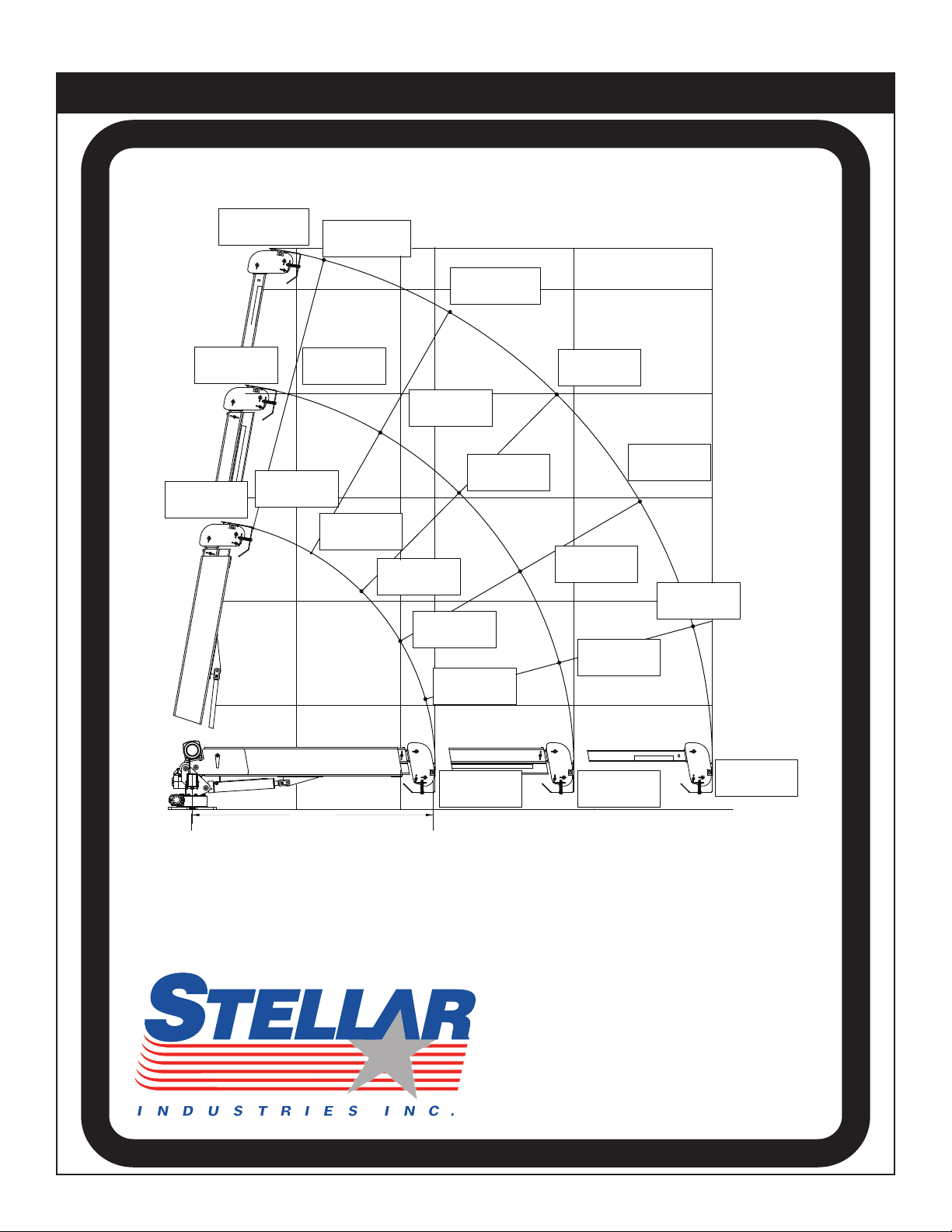
Reach in Feet/Meters
Capacity in Pounds/Kilograms
Weight of load handling devices are
part of the load lifted and must be
deducted from the capacity.
EC3200
PN 42817
Maximum 1 - part line capacity is
1600lbs (725kg). For greater loads,
use 2 - part line.
15º
30º
45º
60º
75º
80º
410 kg
905 lbs
1490 lbs
3200 lbs
1710 lbs
775 kg
3200 lbs
1450 kg
1450 kg
2415 lbs
862 kg
1095 kg
1900 lbs
3200 lbs
1450 kg
675 kg
1372 kg
1450 kg
3200 lbs
1450 kg
3200 lbs
973 kg
2145 lbs
703 KG
*1550 lbs
*3200 lbs
1450 kg
*3025 lbs
890 lbs
290 kg
640 lbs
550 kg
353 kg
780 lbs
492 kg
1085 lbs
404 kg
1215 lbs
1090 lbs
495 kg
83.69
®
710 kg
1565 lbs
Capacity Chart - Decal PN 42817
Page 7

Chapter 2 - Installation
Notice: Read this Page Before Installation of the Crane
Installation
General Installation
This chapter is designed to serve as a
general guide for the installation of a Stellar
EC3200 Crane on a Stellar Service Body.
Each installation is considered unique so
certain portions of this chapter may or may
not apply to your direct application. If a
question should arise during the installation
process, please contact Stellar Customer
Service at (800) 321 3741.
This crane is designed for use with a Stellar
Service Body installed on a vehicle that
meets the minimum chassis requirements of
the crane. It is the installer’s responsibility to
assure that the crane is mounted on a
platform that will support the maximum
crane rating of this crane.
Notice:
PTO and Pump installation instructions are
provided by the corresponding
manufacturers. For more information on
which PTO and Pump fit your application,
please contact your local Stellar Distributor
or Stellar Customer Service.
Important: When installing welder units to the service
bodies, it is highly recommended that a surge
protector is installed on the chassis batteries to protect
the crane radio receiver, wiring and other electronic
devices from an unexpected electrical spike or surge.
Failure to do so could result in extensive damage to
the service body and crane electrical circuit.
Installation Notice
According to Federal Law (49 cfr part 571),
each final-stage manufacturer shall
complete the vehicle in such a manner that
it conforms to the standards in effect on the
date of manufacture of the incomplete
vehicle, the date of final completion, or a
date between those two dates. This
requirement shall, however, be superseded
by any conflicting provisions of a standard
that applies by its terms to vehicles
manufactured in two or more stages.
Therefore, the installer of Stellar cranes and
bodies is considered one of the
manufacturers of the vehicle. As such a
manufacturer, the installer is responsible for
compliance with all applicable federal and
state regulations. They are required to
certify that the vehicle is in compliance with
the Federal Motor Vehicle Safety Standards
and other regulations issued under the
National Traffic and Motor Vehicle Safety
Act.
Please reference the Code of Federal
Regulations, title 49 - Transportation, Volume
5 (400-999), for further information, or visit
http://www.gpoaccess.gov/nara/index.html
for the full text of Code of Federal
Regulations.
Page 8
EC3200 Owner’s Manual
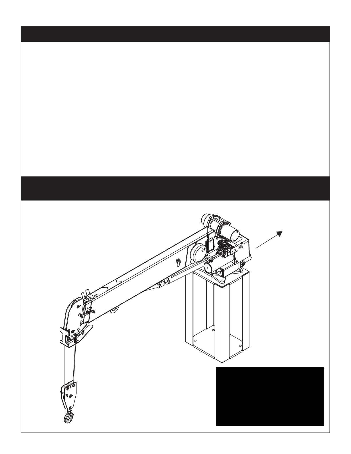
Front of Truck
Installation Overview
1. Determine that the mounting location for the EC3200 crane is at least 18” x 15” (45.7 x 38.1 cm).
2. Use the detail on the following page to drill .938” diameter holes into the mounting plate. Run tap on the
threads of the base to be sure they are clean.
3. Use a crane or lifting device capable of lifting the weight of the Stellar crane. The Stellar EC3200 weighs
approximately 800 lbs (360 kg). Note: cranes are shipped with rotation positioned at 180 degrees from
normal stowed travel position. This will allow for easy installation of the crane and permanent connection
of all hydraulic and electrical components prior to repositioning into the crane saddle.
4. Connect straps or chain from the lifting device to the main boom of the Stellar EC3200.
5. Use four (4)
6. Install a washer on each bolt.
7. Apply Loctite Thread locker #277 to the bolts.
8. Using the lifting device, lower the Stellar EC3200 just above the crane compartment and start the bolts.
Have someone assist in leveling the crane.
9. Secure the crane using the mounting hardware provided. Note: longer or shorter cap screws may be
required – recommended thread engagement into crane base is 0.75” – use grade 8, zinc plated cap
screws only.
10. Torque the cap screws to 454 ft-lbs.
11. Remove supporting crane.
12. Hook-up hydraulics and electrical using the schematics provided at the end of this chapter.
7
⁄8” x 1-3⁄4” #8 bolts and four (4) #8 7⁄8” flat washers.
Note: If questions should arise during any portion of this installation,
please contact Stellar Customer Service at (800) 321-3741.
WARNING!
The use of this crane on a
body not capable of handling
the loads imposed on it may
result in serious injury or
death.
Page 9
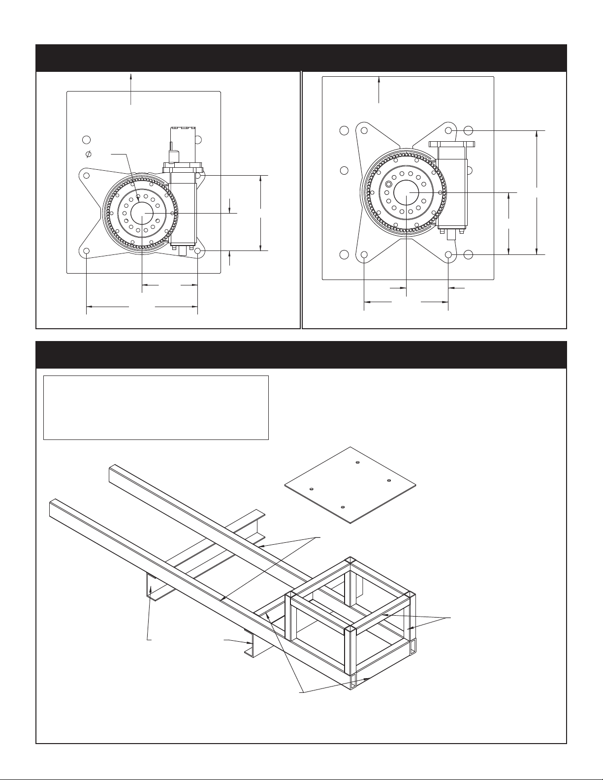
HOLE MOUNTING DETAIL
FRONT
7.38
5.00
10.00
14.75
3.00
EC3200 Mounting Detail
TUBE 4X2X0.38
TRUCK FRAME
TUBE 4X2X0.38
3/8 PLATE
TUBE 2X2X0.38(TYP 4)
HOLE MOUNTING DETAIL
FRONT
7.38
14.75
5.00
10.00
Installation
Standard
Flatbed Body Reinforcement
Narrow
Base
If it has been determined that the destination
body won’t support the crane with a fully
rated load, the body must be reinforced.
Use 1/4” fillet welds and an ASWS qualified
welder to proceed as shown in this drawing:
Note: Tubing must be
at least 4” x 2” x 0.38”
(Except where noted)
Page 10

EC3200 Owner’s Manual
IS PART OF THIS KIT
STABILITY DECAL P/N 16881
NOTE:
2
3
.YTQNOITPIRCSEDTRAPMETI
2 18041 WASHER 0.88 SAE FLAT YELLOW GR94
3 51377 CAP SCR 0.88-9X2.00 HHGR94
Stowed Position
EC3200 Installation Drawing
NOTICE!
Route hoses correctly to ensure
they do not become pinched or
crushed during installation.
Page 11

BOOM UP
BOOM DOWN
MAIN UP
ROTATI ON CCW
ROTATI ON CW
MAIN DOWN
EXT IN
EXT OUT
ROTATION CW
ROTATION CCW
ROTATION
2
05 43847
ITEM
01
02
03
04
42980
42800
PART No.
42983
42981
06
07
09
08
10
42982
42984
C1111
PN 42799
FTG ADAPT MSTR/FSTR 10-6 F5OG5
HOSE KIT 3315 CRANE (incl:2-11)
DESCRIPTION
HOSE-HYD .25 X 20
HOSE-HYD .25 X 22
HOSE-HYD .25 X 23
HOSE-HYD .25 X 19
HOSE-HYD .25 X 42
HOSE-HYD .25X 43
QTY
1ref
1
1ref
1ref
1ref
1ref
1ref
13
11
12
14
15
49315
D1291
C4922
3861
16
MAIN
EXTENSION RETRACT
EXTENSION EXTEND
EXT
FTG ADAPT 4-F5OLO-S
FTG ADAPT 4-6 F5OLO-S
FTG ML FM O'RING 90 DEG
SWITCH PRES OVERLD CD-11C-2900R/WD
1
4
8
1
02 06 07
12 12
03
12 12
12 12
04
05
12
10
12
10
13
14
11
11
11
11
Installation
Hydraulic Kit - PN 42799
Page 12

EC3200 Owner’s Manual
NOTE: P/N 47409 INCLUDES
HARNESS & WINCH CONTROLLER
7,8
9
POWER
GROUND
OPT1
OPT2
WINCH UP RELAY
1
WINCH DOWN
POWER 12 V
3
POWER UNIT SIGNAL
POWER 12 V
2
4,5,6
SWITCH
4,5,6
A2B
PRESSURE SWITCH
RADIO CNTRL ASM 5 FCTN ON/OFF
SWITCH PUSH BUTTON 9216-03
WIRE HARNESS 3315 MULTI FUNCTION VB
PART No.ITEM
42976
17771
42805
03
01
02
DESCRIPTION
COVER SWITCH EC3200
SWITCH MOM SPST 20A
CABLE SEAL 18-20 PACKARD 39000
CONNECT 2 PIN SHROUD PACKARD
CONTACT M TERM SHROUD 14-16 3103406 9756
8384
9752
05
04
47409
47410
08
07
WIRE HARNESS 3315 MULTI FUNCTION VB
FUSE HOLDER 46039
FUSE 250 AMP 4627611 36436
47092
3252310
09
12
QTY
1
1
1
4
4
2
1
1
1
1
1
MAIN
CONTACT
GROUND
PN 42804
7
6
8
5
A
109
4 3
11
2
12
1
87A
30
86
85
87
A
B
B
A
8
5
12
1
B
11
2
10
3
9
4
A
B
B
A
7
6
A
B
B
A
A
B
B
A
A
B
B
A
A
B
B
A
ROTCWROT
CCW
INNER
DOWN
INNER
UP
EXTINEXT
OUT
A
B
A
B
WINCH
DOWN
GROUND
WINCH
UP
REPLACEMENT CONTROLLER
STELLAR P/N 42821
B
A
B
A
B
A
C
Winch
Power
Unit
Control Kit - PN 42804
Page 13

+
-
FUSE 250 AMP
(STELLAR SUPPLIED)
UNDERHOOD
TRUCK BATTERY
MASTER
250 AMP
AUX BATTERY
-
+
CRANE
COMPARTMENT
CAB OR CRANE
10 AMP
POWER
SWITCH
START MOTOR
SOLENOID
GROUND POST
CRANE HARNESS
GROUND
GROUND
LOCATE AUX BATTERY AS
CLOSE TO CRANE AS POSSIBLE
GROUND
POWER
OPT1
OPT2
SWITCH
(NOT SUPPLIED)
POWER SOURCE FOR
RADIO REMOTE
Torque Spec
Large Nuts: 35 in-lbs
Small Nuts: 15 in-lbs
FUSE 250 AMP
(STELLAR SUPPLIED)
Recommended Wire Sizes:
EC3200 - #2
EC4000 - #2
EC5000 - #2
EC6000 - 1/0
EC3200 Wiring Diagram (Two Battery)
Installation
Page 14

EC3200 Owner’s Manual
+
-
FUSE 250 AMP
(STELLAR SUPPLIED)
UNDERHOOD
TRUCK BATTERY
CRANE
COMPARTMENT
CAB OR CRANE
10 A MP
POWER
SWITCH
START MOTOR
SOLENOID
GROUND POST
CRANE HARNESS
GROUND
GROUND
GROUND
POWER
OPT1
OPT2
POWER SOURCE FOR
RADIO REMOTE
Torque Spec
Large Nuts: 35 in-lbs
Small Nuts: 15 in-lbs
SAFETY BRAKE
87A
30
86
85
87
Note:
With a single battery configuration,
operating the crane when the truck
is not running will drain the truck battery.
Recommended Wire Sizes:
EC3200 - #2
EC4000 - #2
EC5000 - #2
EC6000 - 1/0
EC3200 Wiring Diagram (One Battery)
Page 15

ROT
CCW
ROT
CW
INNER
UP
INNER
DOWN
EXT
OUT
EXT
IN
Valve Bank Drawing
Installation
Page 16

EC3200 Owner’s Manual
Stability Procedure
Definition of Stability for the Stellar Telescopic Crane Products:
A truck is stable until the load cannot be lifted off the ground with the winch, without
tipping over the truck. Every Stellar crane installed must be tested for stability to
determine the actual load capacity of the final truck package. The actual test data
must be recorded and supplied with the truck at the time of in-service and should be kept
with the truck at all times. The following procedure will test the truck package for stability
and will provide a stability capacity chart. The load limit information shown on the
stability capacity chart is formulated on 85% tipping.
Set Up:
1. Locate the truck on a test course in position for loading and engage travel brakes.
2. Set stabilizers so that they make contact with firm, level footings.
3. Operate the crane under partial load to assure operator proficiency and proper
machine function.
EC3200 Stability Data
Max Horizontal Reach: 180” (From the center of rotation to boom tip)
Stability Test Weight: 755 lbs.
Test Procedure
1. Rotate the crane into Zone 1 position.
2. With the crane fully retracted and the boom horizontal, winch the test weight off the
ground. Note: Keep weight within six inches of the ground at all times.
3. Extend the boom outward until full extension has been reached or until the truck
becomes unstable (Again, use the winch to keep the weight within six inches of the
ground.)
4. If the boom goes full extension without becoming unstable, the crane is termed stable
for this zone and 100% can be written in the Zone 1 data box.
5. If the truck becomes unstable prior to going full extension, retract the boom until the
truck becomes stable and measure the horizontal reach in this position (center of
rotation to boom tip). This is the stable horizontal reach for this zone. Stable horizontal
reach divided by Maximum horizontal reach multiplied by 100 equals the percentage
of rated capacity for this zone. Use the following formula to determine the percentage
of rated capacity:
6. Record this number in the data box for Zone 1. This is the revised capacity due to
stability for this zone.
7. Repeat this procedure for each zone until the worksheet is completed.
8. This is the revised capacity based on stability of this package.
Page 17

STABILITY CAPACITY CHART
Stability Capacity Chart
Installation
Page 18

EC3200 Owner’s Manual
PART No.
DESCRIPTION
ITEM
QTYQTY
PART No.ITEM
DESCRIPTION
DECAL-ELECTROCUTION 2x2.75
DECAL-ELECTROCUTION 4.5x7.5
DECAL ASME/ANSI B30.22/B30.5
4190
*10
DECAL-DANGER
09
*08
*06
07
*05
*03
*04
02
01
C4540 DECAL-DANGER
DECAL CAPACITY
DECAL-ELECTROCUTION 5x13
DECAL IDENTIFICATION
15172
42818
42817
C4545
DECAL-DANGER
DECAL-ROTATE/GREASE
DECAL-DANGER
C4544
4186
9188
4189
15
14
*12
*13
*11
13819 DECAL-ANGLE INDICATOR SS
DECAL-DANGER O.R.
DECAL ANGLE INDICATOR CS
DECAL-DANGER MOVING O.R.C5918
C4795
13820
C1179
1
1
15171
25
DECAL GREASE WORM DRIVE BEARINGS
DECAL-STELLAR 4x9.5
DECAL HOISTING PERSONNEL
DECAL-CRANE STOWING
DECAL-TWO BLOCKING
DECAL-STELLAR 2x4.5
DECAL MANUAL EXT
DECAL-DIESEL
DECAL-SERVICE
1C0568
*20
2
*16
1
*17
4
*19
2
*18
12451
C5910
12452
C5911
1
*21
1
22
1
24
1
*23
4214
12300
C4541
2
1
1
3
1
1
1
1
DECAL VB CONTROL EC3200
*USE THESE DECALS WITH BODY PACKAGE
DECAL STELLAR MADE IN THE USA
DECAL SNATCH BLOCK CAP 3 TON
DECAL WARNING OVERLOAD DEVICE
DECAL WARNING MANUAL OVERRIDES
DECAL CAUTION STOW HOOK
35234
30
1
2
26
2
27
29
1
2
28
24712
25159
42819
28256
**31
**THESE DECALS NOT INCLUDED WITH THE DECAL KIT
42820
1
1
1
1
1
1
18472 DECAL MANUAL OPERATION 1
PN 42816
30
31
26
9
24
27
29
01
28
14,15
25
22
7
03
02
3030
2020
5050
6060
7070
4040
1010
00
D1196D1196
IndicatorIndicator
8080
AngleAngle
ECEC32003200
4281842818
Decal Kit Placement - PN 42816
Page 19

11
5
3
4
2
6
1
8
7
9
10
9
12
.YTQNOITPIRCSEDTRAPMETI
10023CE ESAB487241
241640BEARING SWING DRIVE 170-00058-1 1
13 MOTOR 80CC EC3200 YMPH-80-H2(R)-K-S-B62487
4 21151GASKET MOTOR 008-10056-1 1 ref
2HS 52.1X31-05.0 RCS PAC7031D5
6 30750 CAP SCR 0.50-13X3.50 HHGR813
10023CE GNIDILS POTS597247
318RG TALF 05.0 REHSAW0970D8
9D1345 FTG CPRSN 0.12NPT/0.25 TUBE2
10 D1810 TBE AIR SAEJ844 TYPE A .25 (RM)1
131.0 EPIP RELPUOC GTF6522C11
12 56589 ZERK 1/8 NPT STRAIGHT LONG THREAD 1
PN 42525
Chapter 3 - Assembly Drawings
Base Assembly - PN 42525
Assembly Drawings
Page 20

EC3200 Owner’s Manual
.YTQNOITPIRCSEDTRAPMETI
1
1
WORRAN 0023CE ESAB416441
3
241640BEARING SWING DRIVE 170-00058-1 1
4 21151GASKET MOTOR 008-10056-1 1 ref
5D1307 CAP SCR 0.50-13X1.25 SH2
6 30750 CAP SCR 0.50-13X3.50 HHGR813
10023CE GNIDILS POTS597247
318RG TALF 05.0 REHSAW0970D8
9D1345 FTG CPRSN 0.12NPT/0.25 TUBE2
10 D1810 TBE AIR SAEJ844 TYPE A .25 (RM)1
131.0 EPIP RELPUOC GTF6522C11
12 56589 ZERK 1/8 NPT STRAIGHT LONG THREAD 1
11
5
3
4
2
6
1
8
7
10
9
12
PN 44613
MOTOR 80CC EC3200 YMPH-80-H2(R)-K-S-B62487
Base Assembly (Narrow Version) - PN 44613
Page 21

9
*
10
4
3
5
12
3
2
13
8
11
1
6
7
MOUNTING HOLE
10
*
14
16 15
16
15
NOTE: WINCH CONTROLLER(P/N 42821)
SHOWN FOR REFERENCE
18
19
22
9
20
21
9
P/N 42798 MUST
GO IN THIS MAST
22
PN 42787
.YTQNOITPIRCSEDTRAPMETI
10023CE TSAM813241
242513 POWER UNIT 12V EC3200 1
342788 WASHER 0.44 SAE FLAT YELLOW GR8 8
442789 CAP SCR 0.44-14X2.25 HHGR8 ZY 7
520362 BUSHING IGUS GFI-1618-08 4
60345 CAP SCR 0.38-16X1.50 HHGR5 2
2TALF 83.0 REHSAW64307
80479 CAP SCR 0.25-20X0.75 HHGR5 2
6SS TALF 52.0 REHSAW7190D9
10 0478 CAP SCR 0.25-20X0.50 HHGR5 3
2TALF 52.0 REHSAW043011
12 43579 CAP SCR 0.44-14X2.75 MOD EC3200 1
13 47411 BRKT OVERRIDE BUTTON EC3200 1
1EPDH 0023CE REVOC5744441
15 0343 WASHER 0.31 USS FLAT ZINC 3
16 0420 CAP SCR 0.31-18X0.75 HHGR5 3
18 5870 WASHER 0.38 STAR EXTERNAL 1
19 0492 CAP SCR 0.38-16X0.75 HHGR5 1
20 51896 BRKT COVER EC CRANES 1
21 30659 NUT 0.25-20 HH NYLOC SS 1
22 C6021 CAP SCR 0.25-20X0.75 BTNHD SS 2
Mast Assembly - PN 42787
Assembly Drawings
Page 22

EC3200 Owner’s Manual
.YTQNOITPIRCSEDTRAPMETI
10023CE MOOB RENNI303241
2 41641WINCH DC2000 WARN 638991
10266 LEER DROC445113
3TALF 52.0 REHSAW04304
1LYNIV KLB 52.0 PMALC6065C5
6 43845 CAP SCR 0.25-20X0.38 HHGR52
1THGIARTS TPN 8/1 KREZ2951c7
8 42508 WEAR PAD 0.50X1.50X2.001
48RG TALF 05.0 REHSAW0970D9
10 13815PC PLATE ANGLE INDICATOR 2
11 C6106 NUT 0.50-13 HHGR5 NYLOC 2
261-8161-ISQ GNIHSUB960021
13 20362BUSHING IGUS GFI-1618-08 1
100.31X00.3 REDNILYC3052441
2T&D 83.6X00.1 NIPPZ5152451
16 9320 PIN CAP 0.44X1.75X0.19 SS6
1T&D 31.5X00.1 NIPPZ6152471
18 42517ZP PIN TEAR DROP 1.00X2.191
19 5591WASHER 0.31 SAE FLAT YELLOW GR81
20 21170 CAP SCR 0.31-18X1.00 HHGR81
21 0345 CAP SCR 0.38-16X1.50 HHGR54
2SS TALF 52.0 REHSAW7190D32
24 0479 CAP SCR 0.25-20X0.75 HHGR53
2KCOL 52.0 REHSAW125052
1LYNIV KLB 05.0 PMALC1800C62
27 C6353 WASHER 0.38 SAE FLAT YELLOW GR86
28 9843 CAP SCR 0.38-16X0.75 HHGR86
4
1
8
14
18
19
20
13
15
16
27
28
16
27
28
10
9
11
17
16
28
28
27
16
15
12
2
21
6
4
5
3
USE ALL HARDWARE, EXCEPT BOLTS.
7
23
24
25
26
MOUNTING HARDWARE WILL
BE PART OF THE WINCH PACKAGE.
24
PN 42512
Main Boom Assembly - PN 42512
Page 23

.YTQNOITPIRCSEDTRAPMETI
1 42311 EXT BOOM 1ST EC32001
100.84X05.1 REDNILYC705242
3D0790 WASHER 0.50 FLAT GR8 9
4 10172 CAP SCR 0.50-13X1.00 HHGR8 ZY1
5 42509 WEAR PAD 0.38X1.38X1.502
6 42312 EXT BOOM 2ND EC32001
7 42978PC FLAT BOOM STOP EC32001
200.4X36.0 HCTIH NIP779248
9 42317 SHEAVE EC3200 5.00 DIA .22R/1.00THK2
2RETTOC 05.2X57.0 NIPPZ4252401
11 0423 MACHY WASHER 0.75ID 10GA4
400.1X521. NIP RETTOC4287321
13 0507 CAP SCR 0.50-13X4.50 HHGR52
14 27710 SPRING ANTI 2 BLOCK SUMMIT2
15 C6106 NUT 0.50-13 HHGR5 NYLOC 3
16 0352 WASHER 0.50 USS FLAT ZINC2
17 35105 SWITCH LIMIT E1117-B9111-6C1
18 D0178 WASHER #10 SAE FLAT ZINC2
19 0505 CAP SCR 0.50-13X3.50 HHGR51
20 D0561 CAP SCR 0.25-20X0.50 BTNHD SS2
21 42505PC PLATE CRADDLE EC32001
22 43846 SCREW #10-24X0.38 SH SS2
PN 42520
2
3
4
8
1
6
5
5
7
20
12
11
9
10
11
12
17
18
22
15
3
14
3
21
16
15
3
13
19
16
8
Extension Boom Assembly - PN 42520
Assembly Drawings
Page 24

8
13
11
12
11
13
4
3
1
2
10
9
1
5
3
7
6
PN 42781
.YTQNOITPIRCSEDTRAPMETI
1 42523PC PLATE SNATCH BLOCK EC32002
2 42317 SHEAVE EC3200 5.00 DIA .22R/1.00THK1
3 0352 WASHER 0.50 USS FLAT ZINC6
4 5468 NUT 0.50-13 HHGR8 NYLOC 3
5 27810 SPACER 3315 SNATCH BLOCK UHMW2
6 16607PC SPACER 3315 SNATCH BLOCK1
7 47868 CAP SCR 0.50-13X2.75 HHGR83
8 42316 WIRE ROPE 7/32 7X19 GAC 65FT1
9 9263 PIN .38X3.00 QUICK RELEASE 1
1NOT 3-ENARC KOOH8106C01
11 0375MACHY WASHER 0.75ID 14GA2
1RETTOC 05.2X57.0 NIPPZ4252421
200.1X521. NIP RETTOC4287331
EC3200 Owner’s Manual
Cable & Hook Assembly - PN 42781
Page 25

.YTQNOITPIRCSEDTRAPMETI
1 20088 CONTROL HANDLE HOUSING 4 FCTN HET1
2 51830 CONTROL HANDLE FACE PLT 5 FCTN1
3 24385 GUARD RADIO SWITCH 4 FCTN1
4 50932 CONTROL HANDLE GRIP LESS TRIGGER HET H21
5 22600 SWITCH TOGGLE HET RADIO 630193005
6 35441 BATTERY TUBE AA HETRONIC RADIO1
7 16975 SWITCH E STOP ASM HETRONIC RADIO1
8 51831 DECAL CONTROL HANDLE 5 FCTN1
4
6
3
NOTE: 1) P/N'S 25999 & 24958 ARE OPTIONAL COVERS
FOR THE SWITCHES AND TRIGGER
1
2
7
5
8
Radio Transmitter Assembly
Assembly Drawings
Page 26

EC3200 Owner’s Manual
This page intentionally left blank.
Page 27

Chapter 4 - Replacement Parts
HYDRAULIC COMPONENTS
PART# DESCRIPTION
42840 HYDRAULIC SWING MOTOR
21151 GASKET - HYDRAULIC SWING MOTOR
42513 POWER UNIT 12V EC3200
44028 VALVE CARTRIDGE - POWER UNIT 12V #19012-D
44027 VALVE COIL - POWER UNIT 12V #1149 4-D
44029 MOTOR 12V - POWER UNIT #08111-1
44030 12V SOLENOID (12volt hydraulic system) #17757
44026 HYDRAULIC RESERVOIR - POWER UNIT 12V #14071
44025 FILL CAP - HYDRAULIC RESERVOIR
9803 C-BALANCE VA LVE
43892 SEAL KIT - MAIN LIFT CYLINDER
43893 SEAL KIT - EXTENSION CYLINDER
49315 PRESSURE SWITCH
42821 CONTROLLER SOLENOID
C2027 O'RING - # 4 FACE SEAL
C2028 O'RING - # 6 FACE SEAL
D1245 O'RING - # 4 SAE
D1246 O'RING - # 6 SAE
ASSEMBLY COMPONENTS
44375 WORM GEAR - ROTATION BEARING
44383 BEARING & SEAL KIT - ROTATION BEARING
44376 BEARING RETAINER - ROTATION BEARING
44377 ADAPTER HOUSING - HYDRAULIC MOTOR
20362 BUSHING 1.00" X 0.50"
0069 BUSHING 1.00" X 1.00"
42508 WEAR PAD 0.38" X 1.50" X 2.00"
42509 WEAR PAD 0.38" X 1.38" X 1.50"
42978 BOOM STOP FLAT
9320 PIN CAP 0.44" X 1.75" X 0.25" SS
C6353 WASHER 0.38 FLAT GR8
13573 CAP SCR. 0.38-16 X 1.00" GR8
0375 MACHINE WASHER -0.75" ID 14GA.
0423 MACHINE WASHER -0.75" ID 10GA.
42317 SHEAVE
42316 WIRE ROPE
42977 HITCH PIN 0.63" X 4.00"
9263 QUICK RELEASE PIN .38 X 3.00"
42505PC CRADLE PLATE
27710 SPRING ANTI-2-BLOCK
C6018 HOOK 3-TON
10709 SAFETY LATCH FOR 3 TON HOOK
C1592 GREASE ZERK
ELECTRICAL COMPONENTS
35105 LIMIT SWITCH
11544 CORD REEL
17771 PUSH BUTTON (12volt hydraulic system)
47410 MOMENTA RY SWITCH
41641 WINCH
28978 BOSCH RELAY
36436 FUSE 250 AMP
RADIO REMOTE COMPONENTS
42976 RADIO REMOTE SYSTEM
50932 HANDLE ASM
16975 E-STOP SWITCH
22600 TOGGLE SWITCH
20088 LOWER TRANSMITTER HOUSING
35441 BATTERY TUBE HOLDER
35916 BACK UP CORD
Replacement Parts
Page 28

Limited Warranty Statement
Stellar Industries, Inc. (Stellar) warrants products designed and manufactured by Stellar to be free from defects in material and workmanship under
proper use and maintenance. Products must be installed and operated in accordance with Stellar’s written instructions and capacities. This warranty
shall cover the following:
Stellar Cranes, Stellar Hooklift Hoists, Stellar Cable Hoists, Stellar Container Carriers, Stellar Service Trucks, and Stellar X-Tra-Lift Systems:
Twelve (12) month warranty on parts from the date recorded by Stellar as the in-service date, not to extend beyond twenty-four (24) months from date
ofmanufacture,
Twelve (12) month repair labor from the date recorded by Stellar as the in-service date, not to extend beyond twenty-four (24) month from date of
manufacture, and
Thirty-six (36) month warranty on all Stellar Manufactured structural parts from the date recorded by Stellar as the in-service date, not to extend beyond
forty-eight (48) months from date of manufacture.
Stellar Tarper Systems:
Twelve (12) month warranty on parts from the date recorded by Stellar as the in-service date, not to extend beyond twenty-four (24) months from date
of manufacture and
Three (3) month repair labor from the date recorded by Stellar as the in-service date, not to extend beyond fifteen (15) month from date of
manufacture.
The in-service date will be derived from the completed warranty registration card. In the event a warranty registration card is not received by Stellar, the
factory ship date will be used.
Stellar’s obligation under this warranty is limited to, and the sole remedy for any such defect shall be, the repair and/or replacement (at Stellar’s option)
of the unaltered part and/or component in question. Stellar after-sales service personnel must be notified by telephone, fax, or letter of any warrantyapplicable damage within fourteen (14) days of its occurrence. If at all possible, Stellar will ship the replacement part within 24-hours of notification by
the most economical, yet expedient, means possible. Expedited freight delivery will be at the expense of the owner.
Warranty claims must be submitted and shall be processed in accordance with Stellar’s established warranty claim procedure. Stellar after-sales service
personnel must be contacted prior to any warranty claim. A return materials authorization (RMA) account number must be issued to the claiming party
prior to the return of any warranty parts. Parts returned without prior authorization will not be recognized for warranty consideration. All damaged parts
must be returned to Stellar freight prepaid; freight collect returns will be refused. Freight reimbursement of returned parts will be considered as part of
the warranty claim.
Warranty service will be performed by any Stellar new equipment distributor, or by any Stellar-recognized service center authorized to service the type
of product involved, or by the Stellar factory in the event of a direct sale. At the time of requesting warranty service, the owner must present evidence
of date of delivery of the product. The owner shall be obligated to pay for any overtime labor requested of the servicing company by the owner, any
field service call charges, and any towing and/or transportation charges associated with moving the equipment to the designated repair/service
provider.
All obligations of Stellar and its authorized dealers and service providers shall be voided if someone other than an authorized Stellar dealer provides
other than routine maintenance service without prior written approval from Stellar. In the case repair work is performed on a Stellar-manufactured
product, original Stellar parts must be used to keep the warranty in force. The warranty may also be voided if the product is modified or altered in any
way not approved, in writing, by Stellar.
The owner/operator is responsible for furnishing proof of the date of original purchase of the Stellar product in question. Warranty registration is the
ultimate responsibility of the owner and may be accomplished by the completion and return of the Stellar product registration card provided with the
product. If the owner is not sure of registration, he is encouraged to contact Stellar at the address below to confirm registration of the product in
question. This warranty covers only defective material and workmanship. It does not cover depreciation or damage caused by normal wear and tear,
accident, mishap, untrained operators, or improper or unintended use. The owner has the obligation of performing routine care and maintenance
duties as stated in Stellar’s written instructions, recommendations, and specifications. Any damage resulting from owner/operator failure to perform such
duties shall void the coverage of this warranty. The owner will pay the cost of labor and supplies associated with routine maintenance.
The only remedies the owner has in connection with the breach or performance of any warranty on the Stellar product specified are those set above.
In no event will Stellar, the Stellar distributor/dealer, or any company affiliated with Stellar be liable for business interruptions, costs of delay, or for any
special, indirect, incidental, or consequential costs or damages. Such costs may include, but are not limited to, loss of time, loss of revenue, loss of use,
wages, salaries, commissions, lodging, meals, towing, hydraulic fluid, or any other incidental cost.
All products purchased by Stellar from outside vendors shall be covered by the warranty offered by that respective manufacturer only. Stellar does not
participate in, or obligate itself to, any such warranty.
Stellar reserves the right to make changes in design or improvement upon its products without imposing upon itself the same upon its products
theretofore manufactured.
This warranty will apply to all Stellar Cranes, Stellar Hooklift Hoists, Stellar Cable Hoists, Stellar Container Carriers, Stellar Service Trucks, Stellar X-Tra-Lift
Systems, and Stellar Tarper Systems shipped from Stellar’s factory after January 1st, 2010. The warranty is for the use of the original owner only and is not
transferable without prior written permission from Stellar.
THIS WARRANTY IS EXPRESSLY IN LIEU OF ANY OTHER WARRANTIES, EXPRESS OR IMPLIED, INCLUDING ANY WARRANTY OF MERCHANTABILITY OR FITNESS FOR
A PARTICULAR PURPOSE. REMEDIES UNDER THIS WARRANTY ARE LIMITED TO THE PROVISION OF MATERIAL AND SERVICES, AS SPECIFIED HEREIN. STELLAR
INDUSTRIES, INC. IS NOT RESPONSIBLE FOR INCIDENTAL OR CONSEQUENTIAL DAMAGES.
Revision Date: February 2010
Document Number: 37040
EC3200 Owner’s Manual
 Loading...