

Page 1
®
Owner’s Manual
Safety, Installation, Maintenance, and Operation
Model V230 Air Compressor
Subject to Change without Notification.
© 2006 American Eagle
American Eagle, Inc.
190 State Street
PO Box 169
Garner, IA 50438
800-392-3015
Fax: 641-923-4889
www.americaneagleacc.com
Manual Part No. 25687
Last Revision: 5/12/06
Page 2

Introduction
American Eagle Compressors are designed to
provide safe and dependable service for a
variety of operations. With proper use and
maintenance, American Eagle Compressors will
operate at peak performance for many years.
This manual contains information vital to the
safe use and efficient operation of this unit.
Following the information provided within this
manual can ensure the longevity of the
compressor. Carefully read and study the
operator’s manual before using the unit. Failure
to adhere to the instructions could result in
property damage or even serious bodily injury to
the operator or others close to the compressor.
A copy of this manual is provided with every
compressor and shall remain with the
compressor at all times. Information contained
within this manual does not cover all
maintenance, operating, or repair instructions
pertinent to all possible situations. This manual
is not binding. American Eagle reserves the
right to change, at any time, any or all of the
items, components, and parts deemed
necessary for product improvement or
commercial/production purposes. This right is
kept with no requirement or obligation for
immediate mandatory updating of this manual.
This product manual is not intended as a
training manual for beginners or unskilled
operators. This manual offers guidelines for
correct and safe usage of the compressor,
maintenance, and troubleshooting. If more
information is required or technical assistance is
needed, please contact AE Technical Support.
Some sections of this manual contain
information pertaining to all American Eagle
manufactured compressors and may or may not
apply to your specific model.
If this manual becomes damaged, misplaced, or
unreadable at any point, or if you feel that any
part of this manual is unclear or incorrect,
please contact AE Technical Support at 800321-3741 or email at
service@americaneagleacc.com
For Technical Questions, Information, Parts, or Warranty, Call Toll-Free at
800-321-3741
Hours: Monday - Friday, 8:00 a.m. - 5:00 p.m. CST
Or email at the following addresses:
Technical Questions, and Information service@americaneagleacc.com
Order Parts parts@americaneagleacc.com
Warranty Information warranty@americaneagleacc.com
V230 Manual
1
Page 3
Table of Contents
Safety Page 3
Specifications Page 4
Operation Page 5
Maintenance Page 6
Installation Page 7
Assembly Drawings Page 8
Replacement Parts Page 13
Troubleshooting Page 14
Warranty Page 16
V230 Manual
2
Page 4

Safety
This manual contains vital information for the safe use and efficient
operation of this unit. Carefully read the operators manual before
starting the unit. Failure to adhere to the instructions could result in
serious bodily injury or property damage.
The V230 Air Compressor will provide safe and
dependable service if operated according to
instructions. Read and understand the safety
precautions given in this manual and on the
decals attached to the shields. Failure to do so
can result in personal injury or equipment
damage.
Operators and maintenance personnel must
always comply with the safety precautions.
These precautions are given here for your
safety. Review them carefully before operating
the compressor and before performing
maintenance or repairs.
Supervising personnel should develop additional
precautions relating to the specific work area
and local safety regulations.
Precautions
Always wear safety equipment such as goggles,
ear plugs and head protection at all times when
operating the compressor.
Establish a training program for all operators to
ensure safe operation.
Do not operate the compressor unless
thoroughly trained or under the supervision of
an instructor.
Do not operate the compressor if it is damaged,
improperly adjusted or not completely or
properly assembled.
Never operate the compressor with any of the
guards removed. Do not attempt to adjust or
disable the compressors air pressure relief
valve. This valve limits the air pressure to 150
PSI.
The surface of the air compressor may reach
temperatures above 150 degrees. Touching
these surfaces during operation can cause
burns.
The air taken in by the air compressor must be
free of flammable fumes and vapors.
Do not inspect or clean the compressor while
the power source is connected. Accidental
engagement of the tool can cause serious
injury.
Before performing any maintenance on the
compressor, place a warning tag on the power
source or disconnect the belt from the
compressor clutch to prevent accidental startup
of the compressor.
V230 Manual
The compressor must be installed in a level
position to provide proper lubrication. Most air
compressor failure is caused by improper
lubrication.
Use and operate this air compressor only in full
compliance with all pertinent O.S.H.A.
requirements and all Federal, State and Local
codes or requirements
3
Page 5
9
1
1
1
31
01
4
1
8
1
0
2
6
7
9
21
5
61
5
1
7
1
1
4
3
2
8
12
01
21
11
31
3
1
2
6
5
4
3
1
9
8
7
41
21
11
31
01
5
1
Specifications
Compressor System Description
• Cast Iron Crankcase Casting • Heavy Ductile Iron Crankshaft
• Cast Aluminum Cylinder Heads • Micro-honed Connecting Rods
• High Temperature Precision Pistons • Tapered Roller Bearings
• Stainless Steel Reed Valves • Pressure Lubricated System
• Heavy Duty Journal Bushings • Oil Pressure Gauge
• Pulsation Manifold
General Information
• Model: V480
• Weight: 87 lbs.
• Displacement @ 1200 RPM: 44 CFM
• Delivery: 28 CFM @ 100 PSI
• Maximum Working Pressure: 155 PSI
• Oil Capacity: 1 Quart
• Cylinders: Four Cylinder(Single Stage)
• Pressure switch presets: Engage - 115 PSI
Disengage - 150 PSI
V230 Manual
4
Page 6
Operation
Each compressor is bench tested under load at the factory to ensure proper break-in and operation.
While it is not necessary to follow any break-in procedure, the following checks should be made
before putting the unit into service and periodically during use.
Before Start-Up
Check the oil level in the compressor with the dipstick on the unit. If oil is needed, use American
Eagle synthetic compressor oil (P/N C0087) or an equivalent synthetic oil. Note: There may be
oil left in the crankcase from the factory bench test. Overfilling may cause the compressor
to back blow oil. Always check the oil level and fill to the designated marking on the
dipstick before putting the unit into service.
Check the air intake filters on each head to make certain that they are clean and unobstructed.
Dirty air filters are a possible cause of reduced air output.
GENERAL INFORMATION
To use the compressor, start the engine and engage the system with the compressor toggle switch.
Through the pressure switch the system will now function automatically. Once engaged, adjust the
engine speed control to ensure that the compressor speed does not exceed 1300 RPM under load.
If questions arise during operation, please call our customer service department at (800) 321-3741
V230 Manual
5
Page 7

Maintenance
The following table is a list of routine maintenance items, including service intervals. Service
intervals are listed as hours, days, or weeks, whichever occurs first. American Eagle recommends
that these service intervals be followed.
Service Intervals
Maintenance operation Daily Weekly Monthly Hourly
Drain air tanks
Check crankcase oil level
Check fittings and airlines
Inspect clutch and belt
Inspect and clean air intake filters
Clean and operate safety valves
Inspect check valve
Inspect and clean compressor valves
Replace air filters 3
Tighten all fittings and fasteners 3
Check all electrical connections 3
Check compressor reed valves 250
Inspect and clean air check valve 250
CHANGE CRANKCASE OIL (see footnote below)
Under normal operating conditions, oil changes are required every 3 months. When operating in a
dirty environment, change the oil more frequently as your particular operating condition dictates.
6
USE
COMPRESSOR CRANKCASE CAPACITY IS TWO QUARTS.
AE SYNTHETIC COMPRESSOR OIL P/N C0087.
V230 Manual
6
Page 8

Installation
COMPONENT INSTALLATION
This section pertains to the installation of the air compressor, and other related items. The
instructions are intended as a guide to assist you with particular installation. These instructions will
provide only general information.
COMPRESSOR INSTALLATION:
Install compressor-mounting kit per manufacturer instructions. Set the compressor into place and
inspect for proper alignment. Readjust if necessary. Using four (4) cap screws, flat washers, and
nyloc nuts, secure the compressor in place. The compressor is air cooled, and must have a clean
supply of air. Adequate space must be provided for proper circulation of air.
Torque and Procedure Chart
Pulsation Chamber Assembly
Torque Value: 31 FT. LBS.
Procedure: See Head Installation Procedure Section
Head Assembly
Torque Value: 31 FT. LBS.
Assemble both heads on the cylinders with head bolts started only, not tight. Set pulsation chamber in place
between heads, making sure the “O” ring is in place in each head. Screw the (4) chamber mounting bolts down but
not tight. Snug (6) head bolts in each head to light torque. Tighten (4) chamber bolts to 31 Ft-lbs. torque. Tighten
(6) head bolts in each head to 31 Ft-lbs. torque, doing the (2) long center bolts first and the (4) short bolts last. After
five hours of use re-torque bolts to 31 Ft-lbs.
Cylinder Assembly
orque V
T
Procedure: After assembling cylinder over pistons and setting into place, tighten (6) cap screws finger tight. In a
criss-cross pattern, tighten bolts evenly so all bolts are hand snug.
20 Ft-lbs., checking each bolt twice. After five hours of use, re-torque bolts to 20 Ft-lbs.
Connecting Rod Assembly
orque Value: 18 FT. LBS.
T
Procedure: Assemble rod onto the crankshaft taking care to align the machined surfaces together and tighten cap
screws finger tight.
assembly of the cylinders.
alue: 20 FT
. LBS.
Again in a criss-cross pattern torque each bolt to
Tighten bolts until hand tight and torque to 18 Ft-lbs. Check twice the torque reading before final
V230 Manual
7
Page 9

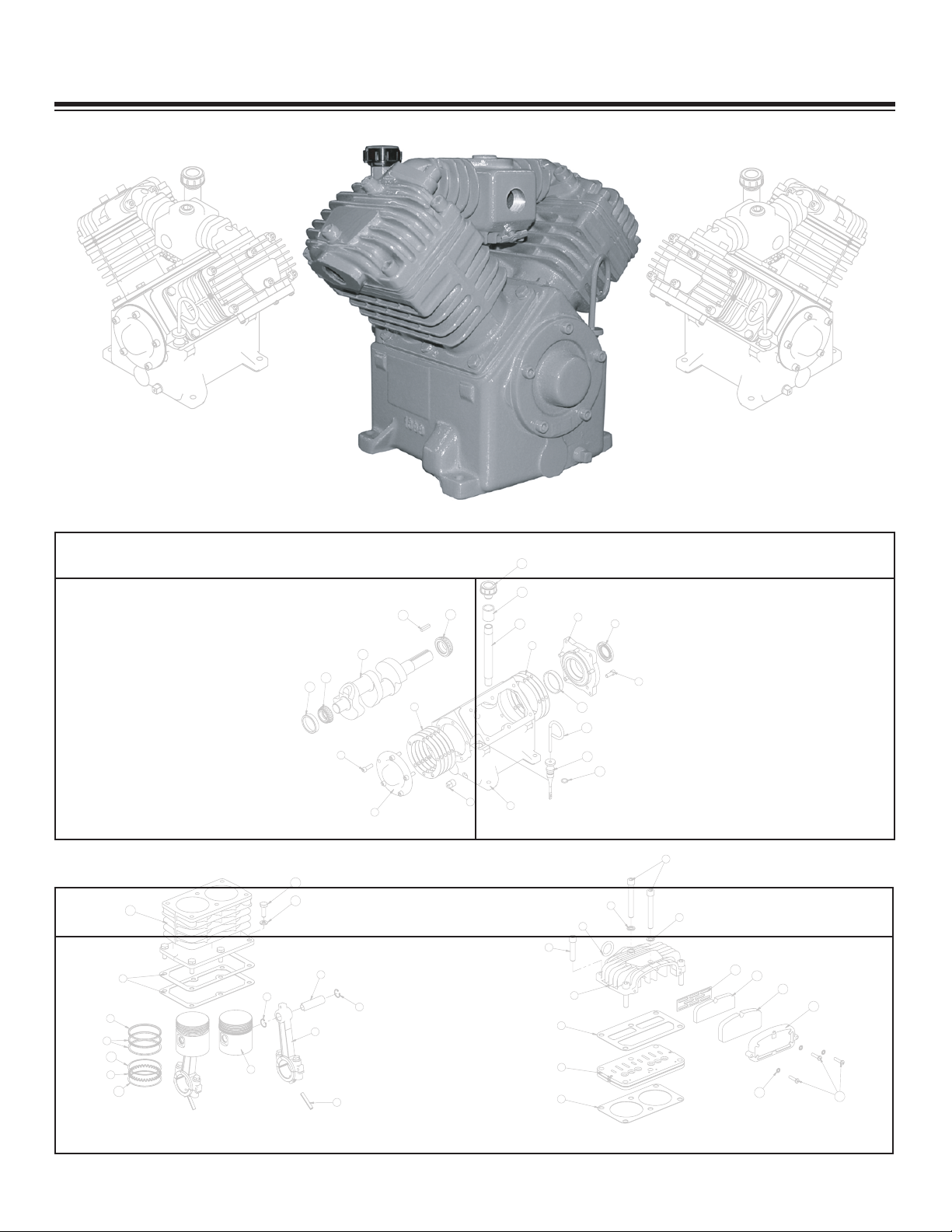
Assembly Drawings
9
1
1
1
3
1
0
1
4
1
8
1
0
2
6
7
9
21
5
6
1
51
71
1
4
3
2
8
1
2
.YTQNOITPIRCSEDTRAP
ME
TI
1032V ESAC KNARC168221
5
)510.
( 084V-REIRRAC GNIRAEB TEKSAG22852
1032V REIRRAC GNIRAEB738223
5CHS 00.1X81-13.0
WERCS
430
6
4
3TEKSAG
LP TNO
RF1726C
5
1
084V
TLP H
CTU
LC REIRRAC GNIRAEB
6285
6
1084V LAES GNIRAEB528
5
7
1GULP NIARD LIO5185
8
5HS 57.0X
81-1
3.0 RCS PAC3185
9
1S 032V TFAHSKNA
RC13822
01
1)01644L( PUC GN
IRA
EB4611C11
1)01076ML( PUC GNIRAEB3611C
21
1ENOC G
NIR
AEB558
0C
3
1
184076ML ENOC GNIRAEB6580C41
1
)063V/032V( KCI
TSP
ID93
822
5
1
1
0
84V KCEHC LIO KCITSPID ELDNAH68622
6
1
1211-GNIR'O1400
C
7
1
1YDOB REHTAERB2600C81
18YN TPN05. RSR
PC REHT
AERB868229
1
1KLB 05.0 REL
PUOC9295C
0
2
14/1 LEEHWYLF YEK7403212
CRANKCASE GROUP
Crankcase Group
V230 Manual
8
Page 10

01
2
1
11
6
5
2
6
3
4
8
3
1
1
9
7
3
1
.YTQNOITPIRCSEDTRAPMETI
G REDNILYC740
0C
12TEKSA
2032V DOR GNITCENNOC8262
22
2
0
5.1X52.0 NIP LL
OR196223
2DO 36.2 NOTSIP
81
02C4
2NIP NOTSIP9651C
5
N NIP NOTSIP GNIR PANS3726C6426-0005
2
REDIVI
D XE
LF 063V LIO GNIR630
6
7
4E
VOO
RG QS 063V NS
RP
C GNIR73
06
8
2NSRPC GNIR5600C9
1 063V REDNILYC5400C01
6KCOL 13.0 REHSAW225011
65RGH
H 00
.1X81-13.0 RCS PAC2290C21
4
LIAR GNIR 063V LIO GNIR763
63
31
CYLINDER GROUP
Cylinder Group
V230 Manual
9
Page 11

2
6
5
4
3
1
9
8
7
41
21
1
1
3
1
01
51
.YTQ
N
OITPIRCSE
DT
RA
P
MET
I
1S/O 032V C/A DAE
H
03061
4
T
LOB DAEH HS 57.1X61-83.0 R
CS PAC
6851C
2
1)SSARB( TLOB DH
GNOL R
EHS
AW
828
53
1LTS TLOB DH REH
SA
W0400C
4
2TLOB DAEH HS 00.3X61-83.0 RCS PAC2851C5
1
5
7-9009 NO
TIV
412
-GNIR'O1920C
6
1
063/03
2/34
1 ETAL
P EVLAV TEKSAG3400C7
1S/O MSA BUS ETALP EVLAV301428
1084/063/032/341 DAEH TEKSAG0130
C9
1
NEERCS RETLIF7920C01
1MAOF RETLIF6920C
1
1
1RENIATER RETLIF4920C21
1
MAOF R
ETLIF5170C3
1
3FN 88.0X23-01# WERCS0030C41
3RSRPC RATS 01# REHSAW5783251
HEAD GROUP
Head Group
3
4
2
1
.YT
Q
NOITPIRCS
EDT
RAPMETI
1EGRAHCSID 063V DLOFINAM17061
4TLOB KN
AT
NOITASLUP 00.1 X 44.06611C2
1KLB SC DH QS TPN 57.0 GULP00063
1084V-KCOC NIARD79754
MANIFOLD DISCHARGE
V230 Manual
10
Page 12

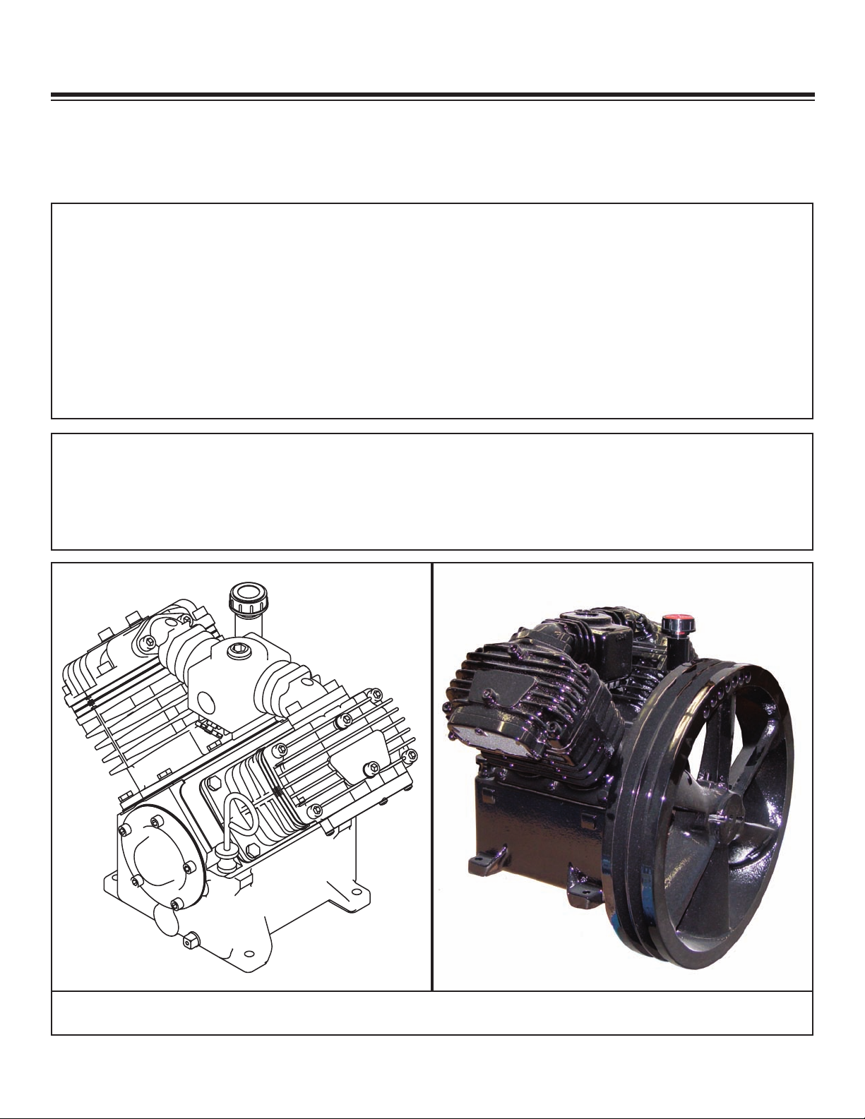
#5808
Aluminum Air Cooled
Imbedded Filter & 3/4”
Threaded NPT Discharge
#C1632
Aluminum Water Cooled
3/4” Threaded Inlet & 3/4”
Threaded NPT Discharge
#22996
Cast Iron Air Cooled
Imbedded Filter & 3/4”
Threaded NPT Discharge
with Head Unloader Ports
#C1631
Aluminum Water Cooled
Imbedded Filter & 3/4”
Threaded NPT Discharge
#15195
C
ast Iron Air Cooled
3/4” Threaded Intake Port
on Top of Head with
3/4” Discharge Port
#3897
Cast Iron Air Cooled
3/4” Threaded Inlet & 3/4”
Threaded NPT Discharge
#23039
Cast Iron Air Cooled
3/4” Threaded Inlet & 3/4“
Threaded NPT Discharge
with Head Unloader Ports
Head Options
V230 Manual
11
Page 13

P/N 23200
ITEM PART DESCRIPTION QTY. ITEM PART DESCRIPTION QTY.
1 22591 BODY HEAD UNLOADER CPRSR 1 6 0220 CAP SCR 0.25-20 X 1.50 HHGR5 5
2 22599 GASKET UNLOADER 1 7 22596 CAP SCR 0.38-16X4.00 SH HEAD BOLT 1
3 22593 PISTON HEAD UNLOADER CPRSR 2 8 C0040 WASHER HD BOLT STL 1
4 22598 O'RING 2-116 HEAD UNLOADER CPRSR 4 9 22597 SPRING PLUNGER PIN UNLOADER CPRSR 2
5 22592 COVER HEAD UNLOADER CPRSR 1 10 22594 PIN PLUNGER HEAD UNLOADER CPRSR 2
Optional Head Unloader
V230 Manual
12
Page 14

Replacement Parts
Overhaul Kit - P/N: 23346
Consisting of: Gasket Set (1)
Gasket Set Complete - P/N: 23668
Ring Set (1)
O-Ring (2)
Valve Plate (2)
Bearing Oil Seal (1)
Oil - 1 Qt
Inner Filter (2)
Outer Filter (2)
Ring Set Complete - P/N: C0069
Valve Plate Assembly - P/N: C0314
Consisting of: Valve Plate (1)
Top Head Gasket (1)
Bottom Head Gasket (1)
Crankshaft With Bearings:
Straight Shaft - P/N: 23689
Canister Filter - P/N: 22867
Call 800-321-3741 to Order
V230 Manual
13
Page 15

Troubleshooting
If symptoms of poor performance develop, the following chart can be used as a guide to investigate
and correct the problem. When diagnosing faults in operations of the air compressor, always check
that the hydraulic power source is supplying the correct hydraulic flow and pressure that is listed in
the compressor specification section of this manual.
Problem
Compressor runs hot
Compressor does not run
Compressor runs too slow
Compressor will not stop
Possible Cause
Check compressor rotation
Compressor reed valves
Dirty intake filter
Low oil Level
Check valve leaking
Air reservoir full
Hydraulic lines not connected
Couplers or hoses blocked
Air load against compressor
Hydraulic pump not working
Hydraulic motor not working
Check valve leaking
Compressor reed valves
Check for hose leaks
Hydraulic flow too low
Hydraulic motor worn
Power unit relief set too low
Hydraulic system too hot
Speed control not working
Air pressure switch set wrong
Leaking hoses or fittings
Solution
Check fittings on hydraulic motor
Inspect, clean or replace valves
Clean filter assembly
Level Add oil if needed
Disassemble, clean, and re-install
Drain and activate pressure switch
Connect lines
Locate and remove restriction
Relieve air pressure
Check flow and pressure settings
Inspect and repair
Disassemble, clean, and reinstall
Inspect, clean or replace valves
Tighten any hose fitting leaking
Check and reset flow
Replace with new motor
Readjust relief valve
Reservoir too small. Add cooler to system.
Check power supply and readjust
Check points and setting on switch
Tighten all fittings and hoses
Air output too low
(air pressure okay)
Compressor cycles
(air not being used)
Low compressor speed
Air filter dirty
Airlines leaking
Check valve plugged
Leaks in air line
Air pressure switch set wrong
Dirt in solenoid valve
V230 Manual
14
Refer to compressor too slow
Inspect and clean
Retighten hoses
Remove and clean check valve
ighten hoses and fittings
T
Check cut-in and cutout settings
Remove and clean
Page 16

Problem
Possible Cause
Solution
Air Output low
Air Pressure Low)
(
ir pressure too low
A
Air pressure too high
High crankcase oil
usage
Blowing oil from
crankcase breather
No lubricating oil
pressure
Dirty air filter
ntake reed valves malfunction
I
Insufficient torque on head bolts
ir pressure switch set wrong
A
Air line leak
Air consumption exceeds
Compressor capacity
Intake or exhaust valves damaged
Pressure switch not operating
Internal contamination
Pressure switch not adjusted
Oil level too high
Oil leaks
Piston rings worn or broken
Blown head gasket
Piston rings worn or broken
Oil level in crankcase too high
Hole in piston
Air lock in oil pump
No oil in crankcase
Pump suction blocked
Inspect and clean filter
If air back-flows from air filter, reed valve is faulty and
needs to be replaced.
Tighten bolts to required torque
eadjust high pressure setting
R
Inspect and tighten loose hoses
Check air demand for items using the air supply
Inspect and replace
Inspect and clean
Inspect and clean
Readjust to lower pressure
Check oil level and drain if needed
Inspect and repair gaskets or seals
Replace rings
Replace gasket
Replace rings
Check oil level and drain
Replace piston
Loosen oil gauge while compressor is running. When
oil begins to flow from fitting, tighten oil gauge.
Check oil level and add
Remove oil intake plug and inspect intake and screen.
Clean blockage.
V230 Manual
15
Page 17

Limited Warranty Statement
®
American Eagle warrants products designed and manufactured by Stellar to be free from defects in material and workmanship under proper use
and maintenance. Products must be installed and operated in accordance with Stellar’s written instructions and capacities. The warranty period
shall cover the following:
Twelve (12) month warranty on parts and
Twelve (12) month repair labor
The warranty period shall begin from the date recorded by American Eagle as the in-service date. This date will be derived from the completed
warranty registration card. In the event a warranty registration card is not received by American Eagle, the factory ship date will be used. New
compressors will be issued on all returns within 90 days of this factory ship date. After 90 days, American Eagle reserves the right to issue
remanufactured compressors. Regardless of in-service date, warranty coverage does not extend beyond twenty-four (24) months from date of
manufacture.
American Eagle’s obligation under this warranty is limited to, and the sole remedy for any such defect shall be, the repair and/or replacement (at
American Eagle’s option) of the unaltered part and/or component in question. American Eagle after-sales service personnel must be notified by
telephone, fax, or letter of any warranty-applicable damage within fourteen (14) days of its occurrence. If at all possible, American Eagle will ship
the replacement part within 24-hours of notification by the most economical, yet expedient, means possible. Expedited freight delivery will be at
the expense of the owner
.
Warranty claims must be submitted and shall be processed in accordance with American Eagle’s established warranty claim procedure. American
Eagle after-sales service personnel must be contacted prior to any warranty claim. A return materials authorization (RMA) account number must
be issued to the claiming party prior to the return of any warranty parts. Parts returned without prior authorization will not be recognized for
warranty consideration. All damaged parts must be returned to American Eagle freight prepaid; freight collect returns will be refused. Freight
reimbursement of returned parts will be considered as part of the warranty claim.
Warranty service will be performed by any American Eagle new equipment distributor, or by any American Eagle-recognized service center
authorized to service the type of product involved, or by the American Eagle factory in the event of a direct sale. At the time of requesting
warranty service, the owner must present evidence of date of delivery of the product.
The owner shall be obligated to pay for any overtime labor
requested of the servicing company by the owner, any field service call charges, and any towing and/or transportation charges associated with
moving the equipment to the designated repair/service provider
.
All obligations of American Eagle and its authorized dealers and service providers shall be voided if someone other than an authorized American
Eagle dealer provides other than routine maintenance service without prior written approval from
American Eagle. In the case repair work is
performed on a American Eagle-manufactured product, original American Eagle parts must be used to keep the warranty in force. The warranty
may also be voided if the product is modified or altered in any way not approved, in writing, by American Eagle.
The owner/operator is responsible for furnishing proof of the date of original purchase of the American Eagle product in question. Warranty
registration is the ultimate responsibility of the owner and may be accomplished by the completion and return of the American Eagle product
registration card provided with the product. If the owner is not sure of registration, he is encouraged to contact American Eagle at the address
below to confirm registration of the product in question. This warranty covers only defective material and workmanship. It does not cover
depreciation or damage caused by normal wear and tear
, accident, mishap, untrained operators, or improper or unintended use. The owner has
the obligation of performing routine care and maintenance duties as stated in American Eagle’s written instructions, recommendations, and
specifications. Any damage resulting from owner/operator failure to perform such duties shall void the coverage of this warranty. The owner will
pay the cost of labor and supplies associated with routine maintenance.
The only remedies the owner has in connection with the breach or performance of any warranty on the American Eagle product specified are
those set above. In no event will
American Eagle, the American Eagle distributor/dealer, or any company affiliated with American Eagle be liable
for business interruptions, costs of delay, or for any special, indirect, incidental, or consequential costs or damages. Such costs may include, but
are not limited to, loss of time, loss of revenue, loss of use, wages, salaries, commissions, lodging, meals, towing, hydraulic fluid, or any other
incidental cost.
All products purchased by
American Eagle does not participate in, or obligate itself to, any such warranty
American Eagle from outside vendors shall be covered by the warranty offered by that respective manufacturer only.
.
American Eagle reserves the right to make changes in design or improvement upon its products without imposing upon itself the same upon its
products theretofore manufactured.
This warranty will apply to all
American Eagle Drawer Sets and Compressed Air Systems shipped from American Eagle’s factory after July 1,
2005. The warranty is for the use of the original owner only and is not transferable without prior written permission from American Eagle.
THIS WARRANTY IS EXPRESSLY IN LIEU OF ANY OTHER WARRANTIES, EXPRESS OR IMPLIED, INCLUDING ANY WARRANTY OF
MERCHANTABILITY OR FITNESS FOR A PARTICULAR PURPOSE. REMEDIES UNDER THIS WARRANTY ARE LIMITED TO THE
PROVISION OF MATERIAL AND SERVICES, AS SPECIFIED HEREIN. AMERICAN EAGLE INDUSTRIES, INC. IS NOT RESPONSIBLE FOR
INCIDENTAL OR CONSEQUENTIAL DAMAGES.
Revision Date: March 2006 Document Number: 37042
Page 18

Page 19

 Loading...