

Page 1
®
Owner’s Manual
Safety, Installation, Maintenance, and Operation
Model SHD-66DD
Subject to Change without Notification.
© 2006 American Eagle
American Eagle, Inc.
190 State Street
PO Box 169
Garner, IA 50438
800-392-3015
Fax: 641-923-4889
www.americaneagleacc.com
Manual Part No. 37243
Last Revision: 7/09/07
Page 2
AE Compressor Manual Revisions
Date of Revision
September 19, 2006
Manuals Effected
SHD-66
Section Revised
Assembly Drawings
Description of Revision
Updated the Compressor
Assembly Drawing to reflect
engineering changes.
SHD-66DD Manual
Page 3

Introduction
American Eagle Compressors are designed to
provide safe and dependable service for a
variety of operations. With proper use and
maintenance, American Eagle Compressors will
operate at peak performance for many years.
This manual contains information vital to the
safe use and efficient operation of this unit.
Following the information provided within this
manual can ensure the longevity of the
compressor. Carefully read and study the
operator’s manual before using the unit. Failure
to adhere to the instructions could result in
property damage or even serious bodily injury to
the operator or others close to the compressor.
A copy of this manual is provided with every
compressor and shall remain with the
compressor at all times. Information contained
within this manual does not cover all
maintenance, operating, or repair instructions
pertinent to all possible situations. This manual
is not binding. American Eagle reserves the
right to change, at any time, any or all of the
items, components, and parts deemed
necessary for product improvement or
commercial/production purposes. This right is
kept with no requirement or obligation for
immediate mandatory updating of this manual.
This product manual is not intended as a
training manual for beginners or unskilled
operators. This manual offers guidelines for
correct and safe usage of the compressor,
maintenance, and troubleshooting. If more
information is required or technical assistance is
needed, please contact AE Technical Support.
Some sections of this manual contain
information pertaining to all American Eagle
manufactured compressors and may or may not
apply to your specific model.
If this manual becomes damaged, misplaced, or
unreadable at any point, or if you feel that any
part of this manual is unclear or incorrect,
please contact AE Technical Support at 800321-3741 or email at
service@americaneagleacc.com
For Technical Questions, Information, Parts, or Warranty, Call Toll-Free at
800-321-3741
Hours: Monday - Friday, 8:00 a.m. - 5:00 p.m. CST
Or email at the following addresses:
Technical Questions, and Information service@americaneagleacc.com
Order Parts parts@americaneagleacc.com
Warranty Information warranty@americaneagleacc.com
SHD-66DD Manual
1
Page 4
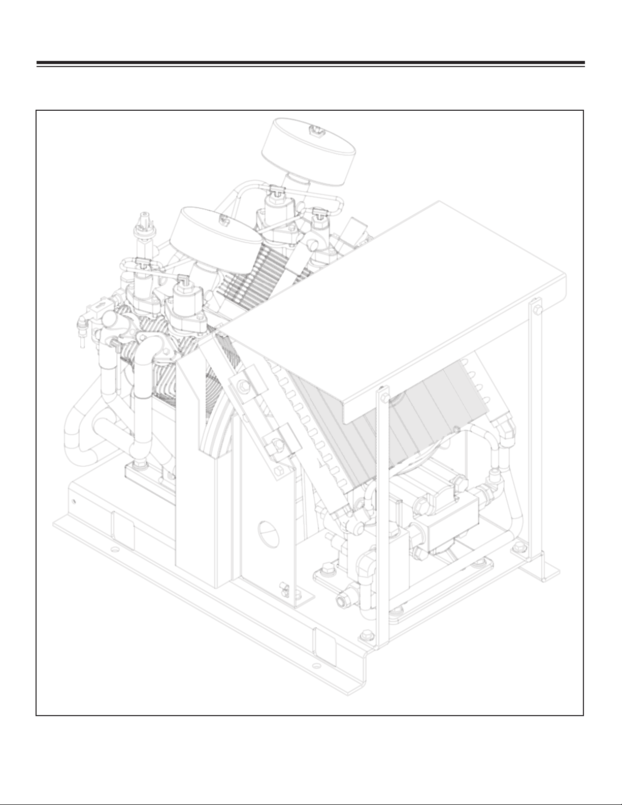
Table of Contents
Safety Page 3
Specifications Page 4
Operation Page 5
Head Unloading System Page 6
Maintenance Page 7
Installation Page 8
Assembly Drawings Page 13
Replacement Parts Page 18
Troubleshooting Page 19
Warranty Page 21
SHD-66DD Manual
2
Page 5

Safety
This manual contains vital information for the safe use and efficient
operation of this unit. Carefully read the operators manual before
starting the unit. Failure to adhere to the instructions could result in
serious bodily injury or property damage.
The SHD-66DD Hydraulic Air Compressor will
provide safe and dependable service if operated
according to instructions. Read and understand
the safety precautions given in this manual and
on the decals attached to the shields. Failure to
do so can result in personal injury or equipment
damage.
Operators and maintenance personnel must
always comply with the safety precautions.
These precautions are given here for your
safety. Review them carefully before operating
the compressor and before performing
maintenance or repairs.
Supervising personnel should develop additional
precautions relating to the specific work area
and local safety regulations.
Precautions
Always wear safety equipment such as goggles,
ear plugs and head protection at all times when
operating the compressor.
Do not inspect or clean the compressor while
the hydraulic power source is connected.
Accidental engagement of the tool can cause
serious injury.
Before performing any maintenance on the
compressor, place a warning tag on the
hydraulic power source or disconnect the hoses
from the compressor motor to prevent
accidental startup of the compressor.
Always connect hoses to the compressor before
energizing the hydraulic power source. Be sure
all hose connections are tight, both air and
hydraulic.
Establish a training program for all operators to
ensure safe operation.
Do not operate the compressor unless
thoroughly trained or under the supervision of
an instructor.
Do not operate the compressor if it is damaged,
improperly adjusted or not completely or
properly assembled.
Never operate the compressor with any of the
guards removed.
Do not attempt to adjust or disable the
compressors air pressure relief valve. This
valve limits the air pressure to 175 PSI.
The surface of the air compressor and the
plumbing between the compressor and the
cooler may reach temperatures above 150
degrees. Touching these surfaces during
operation can cause burns.
The air taken in by the air compressor must be
free of flammable fumes and vapors.
Compressor speed should not exceed 1000
RPM.
Use and operate this air compressor only in full
compliance with all pertinent O.S.H.A.
requirements and all Federal, State and Local
codes or requirements.
SHD-66DD Manual
3
Page 6
4
6
3
4
5
5573656
3
5
3
9
2
4
3
8
4
2
3
525
0
242
903
4
2
033
2
2
8
348
3
442
4
05850
4
254
3
Specifications
Drive System Description
• 16 GPM Hydraulic System • 2000 PSI System Pressure
• 2500 PSI Pressure Relief Setting • 12 VDC Solenoid Control Valve
• All Steel Plumbing W/ JIC Fittings • 165 Sq. In., 300 BTU Cooler
• 861 CFM, 12 Volt Cooler Fan • 6061 Aluminum Manifold
• Direct Drive Coupling • Air Pressure Control Valve
Compressor System Description
• Cast Iron Crankcase Casting • Tapered Roller Main Bearings
• Gasket-free Integrated Cylinder/Head • Heavy Ductile Iron Crankshaft
• Precision Balanced Flywheel • Pressure Relief Valves in interstage
and discharge
• Large Diameter Finned Inner Cooling Tubing • Splash Lubricated System
• Positive Acting Centrifugal Head Unloaders • Preset Pilot Control Valve
General Information
• Model: Champion R30D
• Weight: 425 lbs. (dry)
• Cylinders: Four Cylinder(Two Stage)
• Delivery: 46 CFM @ 175 PSI
• Maximum Working Pressure: 175 PSI
• Maximum Compressor Speed: 1000 RPM
• Dimensions: (w/o reservoir) 33.5”L x 23.5”W x 25.5”H
(w/ reservoir) 48.5”L x 23.5”W x 25.5”H
• Electrical: 12 VDC
• Crankcase Oil Capacity: 4 Quart
• Oil Reservoir Capacity: 16 Gallons
SHD-66DD Manual
4
Page 7

Operation
Each compressor is bench tested under load at the factory to ensure proper break-in and operation.
While it is not necessary to follow any break-in procedure, the following checks should be made
before putting the unit into service and periodically during use.
Before Start-Up
Inspect unit for any visible signs of damage.
Check the oil level in the compressor with the dipstick on the unit. If oil is needed, use American
Eagle synthetic compressor oil (P/N C0087) or an equivalent synthetic oil.
left in the crankcase from the factory bench test. Overfilling may cause the compressor to
back blow oil. Always check the oil level and fill to the designated marking on the dipstick
before putting the unit into service.
Check hoses (air and hydraulic) for weak or worn condition and make sure that all connections are
secure.
Check the air intake filters on each head to make certain that they are clean and unobstructed.
Dirty air filters are a possible cause of reduced air output.
Note: There may be oil
General Information
To use the compressor, start the vehicle engine
and engage the hydraulic system. The
compressor can now be activated using the
compressor switch. This energizes the hydraulic
solenoid sending oil to the hydraulic drive motor
and starts the compressor. Through the air
pressure switch and pilot valve, the system will
now function automatically. Once engaged,
adjust the engine speed control to ensure that
the compressor speed does not exceed 1000
RPM under load. Adjustment instructions are
provided with the speed control unit.
Air Pilot Valve Operation
(Head Unloading System)
When the hydraulic system is engaged the
compressor will pump air into the receiver until
the pressure reaches 175 psi.
air pilot valve senses the pressure in the
receiver and engages an intake valve hold-open
mechanism. The compressor will run free until
the pressure in the receiver falls below 145 psi
and the air pressure valve disengages the
intake valve hold-open mechanism to allow the
At this time the
compressor to pump air. See head unloading
system for detailed views and adjustment
instructions on the next page.
Operating Notes:
This reciprocating compressor must not be used
for breathing air. To do so will cause serious
injury whether air is supplied direct from the
compressor source or to breathing tanks for
later use. Any and all liabilities for damage or
loss due to injuries, death and/or property
damage, including consequential damages
stemming from the use of this compressor to
supply breathing air will be disclaimed by the
manufacturer.
The use of this compressor as a booster pump
and/or to compress a medium other than
atmospheric air is strictly non-approved and can
result in equipment damage and/or injury
approved uses will also void the warranty.
Never use plastic pipe or improperly rated
metal pipe. Improper piping materials can burst
and cause injury or property damage.
. Non-
SHD-66DD Manual
5
Page 8
Intake Valve
Hold-Open
Mechanism
(Route to Air Pilot Valve)
Head Unloading System
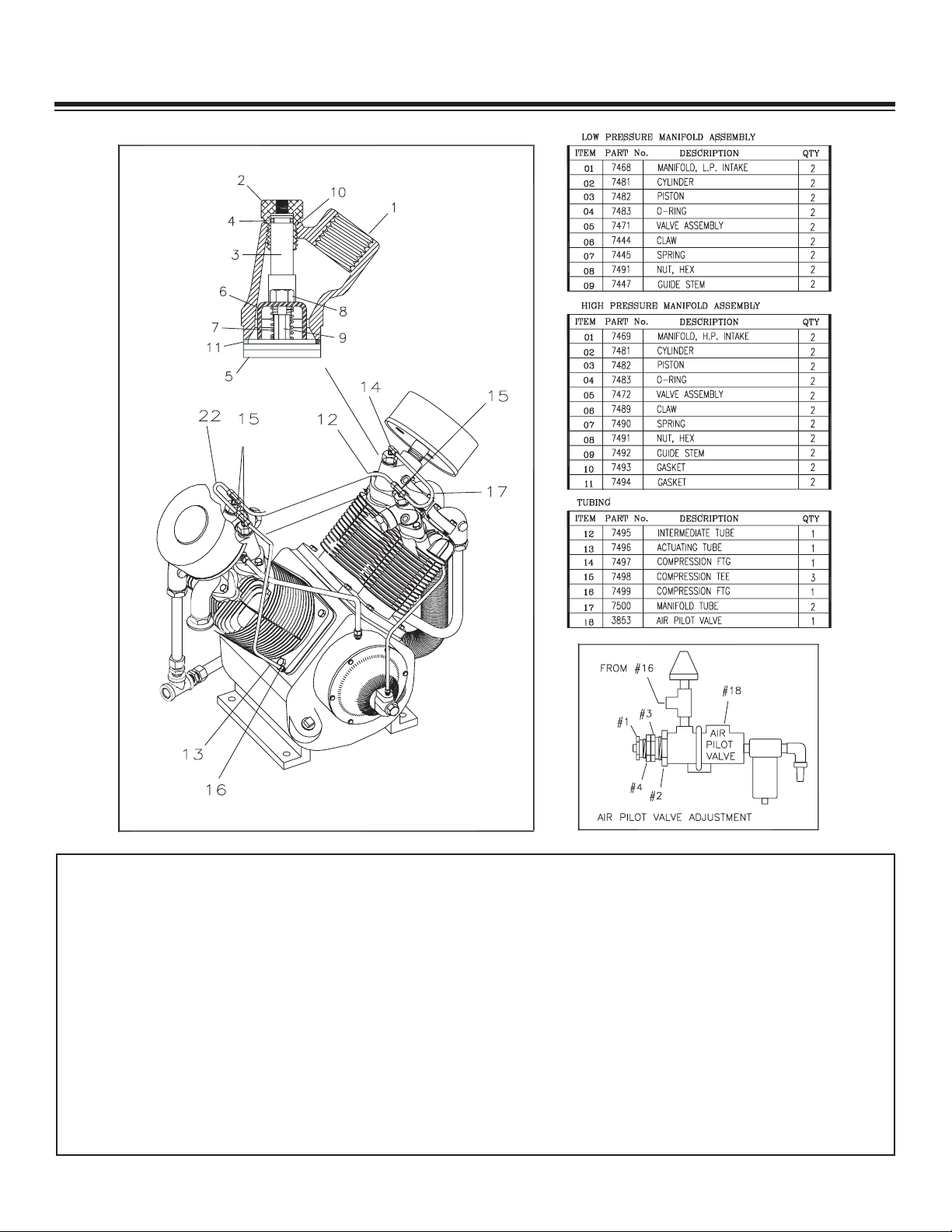
Air Pilot Valve Adjustment
(See Air Pilot Valve Adjustment Detail)
High Pressure Adjustment: Proceed with the following
while the compressor is running.
1.) Loosen locknut (4) and back off several turns. Do
not turn differential adjuster (3).
2.) Check reading on the tank pressure gauge. Set the
compressor maximum pressure at 175 psi. Over
pressurizing compressor will cause damage and
urn threaded cap (1) clockwise to
T
void warranty
increase pressure or counterclockwise to decrease
pressure.
After pressure is set, tighten locknut (4). Be careful
3.)
not to move the threaded cap (1).
.
Differential Pressure Adjustment: Proceed with the
following while the compressor is running.
1.) Loosen locknut (2) and back off several turns.
2.) Check reading on the tank pressure gauge. Set the
pressure to 30 psi differential (unload at 175 psi,
reload at 145 psi). Turn nut (3) clockwise to increase
differential pressure or counterclockwise to decrease
differential pressure.
3.) After pressure is set, tighten locknut (2). Be careful
not to move nut (3)
SHD-66DD Manual
6
Page 9

Maintenance
The following table is a list of routine maintenance items, including service intervals. Service
intervals are listed as hours, days, or weeks, whichever occurs first. American Eagle recommends
that these service intervals be followed. Before performing any maintenance function “Lock Out” or
“Tag Out” all sources of power. Be sure all air pressure in unit is relieved. Failure to do so may
result in injury or equipment damage.
Service Intervals
Maintenance operation Daily Weekly Monthly Hourly
Drain air tanks
Check crankcase oil level
Check fittings and airlines
Check hydraulic fluid level
Inspect and clean air intake filters
Clean and operate safety valves
Clean cooling fins on radiator
Inspect check valve
Inspect and clean compressor valves 6
Replace hydraulic filter 6
Replace air filters 3
Tighten all fittings and fasteners 3
Check all electrical connections 3
Inspect and clean air check valve 250
CHANGE CRANKCASE OIL (see footnote below)
Under normal operating conditions, oil changes are required every 3 months. When operating in a
dirty environment, change the oil more frequently as your particular operating condition dictates.
USE AE SYNTHETIC COMPRESSOR OIL P/N C0087.
COMPRESSOR CRANKCASE CAPACITY IS 4 QUARTS.
General preventative maintenance includes maintaining proper fluid level in both systems and the
general cleanliness of the equipment. Proper fluids according to the specifications are required.
SHD-66DD Manual
7
Page 10

Installation
Power
Source
Toggle
Switch
In Cab
Indicator
Light
In Cab
(Recommended)
Orange Wire To
Speed Control
Compressor
Pressure
Switch
Compressor
Cooling Fan
Solenoid
Valve
Fuse
Red
Black
Black
Blue
NO
C
N
C
COMPONENT INSTALLATION
This section pertains to the installation of the air compressor, PTO, pump and other related items.
The instructions are intended as a guide to assist you with particular installation. These instructions
will provide only general information.
Pump Assembly:
The pump assembly may either be installed
directly on the PTO or as an optional method,
may be driven by a driveline from the PTO.
Pump manufacturers provide specific installation
information for their products and should be
consulted if questions arise.
PTO Assembly:
Check with the PTO manufactures
representative for specific instructions regarding
your particular make, model, and year of
vehicle. As some trucks may require
modification of the transmission cross member
and the exhaust system, the manufacturer’s
instructions should be followed to insure proper
installation of the PTO.
Compressor Assembly:
Prepare the mounting location of the
compressor by locating and drilling four (4)
holes, 9/16” diameter as per the mounting
pattern of the air compressor base. Using four
(4) 1/2” x 1.50” GR-5 cap screws, 1/2” flat
washer, and 1/2” nyloc nut, secure the
compressor in place. The compressor is air
cooled, and must have a clean supply of cooling
air to the fan with minimum restrictions.
Adequate space must be provided for proper
circulation of air.
a toggle switch in a convenient location.
Connect one terminal to the compressor
pressure switch and the other terminal to a 12volt power supply. Add a 20 amp fuse between
the battery and switch. A third wire is required
from the air compressor pressure switch when
connecting the speed control into the system.
(See drawing below)
Electric speed control:
An optional electric or electronic speed control
must be used to maintain proper operating
speed of the air compressor. The engine speed
control will automatically increase from idle to a
preset speed when engaged and decrease
when disengaged. The electric speed control
(American Eagle P/N C0873) is used on most
gasoline engines. The electronic speed controls
are used only on Ford 6.0 and 7.3L diesel
engines. Proper installation instructions are
provided with each system.
Electrical Connections:
From the solenoid valve (located on the
hydraulic manifold) there are two (2) wires, red
and black, running to the compressor pressure
switch. Connect the black wire to the vehicle
frame or other suitable ground. The red wire
mounts to the pressure switch as shown. Install
SHD-66DD Manual
8
Page 11

1
-1/4” Hydraulic Suction Hose
Length as Required
Connect 1-1/4” Suction Hose
t
o 1-1/4” Barb Fitting.
N
ote: There are (2) Locations
t
hat you can Plumb the
Sunction Hose (Side and Bottom)
Stellar
S
upplied
R
eservoir
Motor Case Drain Routed to Hydraulic Reservoir
R
emove Shipping Cap to
Install Pressure Line
1
/2” High Pressure
Hydraulic Hose
L
ength as Required
H
ydraulic Pump
A
dapter as
Required to
F
it Your Pump
1-1/4” Barb/Adapter
t
o Fit You r Pump
See Detail A
See Detail B
1/4” Ho se
3/4” Hose
Air Line
To Air Tank
Check Valve
Air Sense Line
to Air Tank
Detail A
Detail B
NO
NC
C
Component Installation Continued...
Hydraulic System:
Installed on the compressor is a valve block assembly that controls the flow to the hydraulic
motor. To this block, a 1/2” high-pressure hose must be attached. This hose comes from the
hydraulic pumps pressure side. A 1-1/4” hydraulic suction hose must be installed from the
hydraulic reservoir to the hydraulic pump. (See drawing above) Note: For compressors
purchased without a reservoir a 3/4” minimum low-pressure return line is connected to the oil
cooler outlet and is routed to the oil reservoir. The case drain line from the hydraulic motor is
also routed to the oil reservoir. American Eagle recommends a sufficient sized reservoir be
provided which includes the proper suction and return filters. The cooler on the compressor is
designed and sized to cool the air compressor efficiently. An auxillary oil cooler is required
when additional hydraulically operated equipment are added to the hydraulic system. Pressure
on the return line exceeding 200 PSI can and will cause damage to the filter, cooler, and
components of the compressor hydraulic system.
Air System:
Two (2) airlines must be routed to the air tank for
proper installation. The main airline is routed from the
check valve to the air tank using a 3/4”(200psi) air
hose. This is the main delivery line and should be free
from all obstructions. A 3/4” line is routed from the air
pressure valve to the air tank. This line senses the
pressure in the tank and will engage and disengage
the compressor automatically.
SHD-66DD Manual
9
Page 12

PN 30533
PN 30532
Typical Hydraulic Circuit for Single Stage Pump with
Multiple Components
Typical Hydraulic Circuit for Tandum (Two Part) Pump with
Multiple Components
SHD-66DD Manual
10
Page 13

Typical Hydraulic Circuit for Compressor
COMPRESSOR
RETURN
PRESSURE
AUXILIARY
COOLER
SINGLE
HYDRAULIC
PUMP
SUCTION PORT
FILTER
FILTER SCREEN
HYDRAULIC
RESERVOIR
with Auxiliary Cooler
SHD-66DD Manual
11
Page 14

49
65
66
65
64
63
62
61
70
69
67
68
1
19
20
17
47
24
18
45
41
52
21
22
9
40
52
44
46
58
3
4
5
43
3
4
2
8
7
6
13
1
4
11
28
26
28
60
33
31
2
9
33
32
14
27
15
16
12
15
14
10
56
51
53
54
55
2
56
3
4
5
56
57
48
39
38
37
36
30 34
35
50
21
.YTQNOITPIRCSEDTRAPMETI
138525 BASE WLDMT SHD66DD ENCLOSURE 1
2 D1346 CPRSR CHMP R30DHU SPECIAL 1
3 D0790 WASHER 0.50 FLAT GR8 12
8KCOL 05.0 REHSA
W
525
0
4
50359 CAP SCR 0.50-13X1.50 HHGR5 8
6 D0792 COUPG 3/8 KW L150-1.75 1
7 D0793 COUPG SPIDER L150-U BLUE URETHANE 1
8 D0791 COUPG 1/4 KW L150-1.00 1
919645PC BRKT MOTOR MOUNT
19645 POWDERCOAT 1
10 D0786 BRKT WLDMT COOLER MNT LH SHD66DD 1
11 D0824 BRKT WLDMT COOLER MNT RH SHD66DD 1
1DD66DHS TFIL TKRB6580D21
4
K
COL 83
.0 REHSAW3250
31
14 0351 CAP SCR 0.38-16X1.00 HHGR5 12
8COLYN HH 61-83.0 TUN743051
1L
IO RELOOC921
1C
61
17 C3075 BLOCK AL CPRSR SHD 66 1
1GED 09 G
TF5
4
16C8
1
19 C4914 VALVE RELIEF CP-200-1-B-0-A-C 1
1DNLOS EVLAV3194C02
2N
O
5P
-21 GULP 57.0 GTF5106C
12
22 D1189 FTG ST TH CONNECT JIC 8-12 F5OX 1
23 D0613 SCREW SELF TAP #14X0.75 HWH SLOTTD 1
24 C4227 FTG MF/MSTR 90 8-12 C5OLO-S 1
.YTQNOITPIRCSE
DT
RAPMETI
1LYNIV KLB 52.0 PMALC6065C52
1LYNIV KLB 05.0 PM
AL
C
180
0C6
2
48RG TALF 83.0 REHSAW35
36C72
28 D1116 FTG STR THREAD ELBOW 45 DEG 2
29 d0840 FAN 12.00 PUSH 12 VOLT SPL 301003 1
30 4703 BRKT UNLOADER VALVE MNT SHD66DD 1
31 D0075 SCREW #6-32X2.75 RH HD MACHINE 2
2COLYN HH 23-6# TUN6700D23
33 5290 WASHER #8 SAE FLAT ZP 4
34 8277 FTG ST L 0.25 MNPT/0.125 FNPT SPL 1
1SBBOH SERP HCTIWS4680C53
36 20330 FTG 0.38-0.25 FF HEX NIPPLE 1
37 C5662 FILTER METAL BOWL 0.25 1
38 5418 ST EL 0.25 90 DEG BRASS 1
39 C2274 FTG HOSE BARB .25 HOSE X .25 MNPT 1
40 42029 MOTOR HYD M197A731QQDA17-32 3.45 1
41 C5549 FTG ORB/JIC STRT CONNT 12-F5OX-S 1
42 0501 CAP SCR 0.50-13X2.00 HHGR5 4
43 C6106 NUT 0.50-13 HHGR5 NYLOC 4
44 C4671 FTG 8-12 C50X JIC 90 DEG 1
45 D1081 TUBE ASM 0.75 BTTM CLR SHD66DD 1
46 D1079 TUBE ASM 0.50 PRES SHD66DD 1
1S-LNF8 PAC277274
48 D1254 CAP 0.38 PIPE HEX 5406-CAP-6 1
.YTQNOITPIRCSEDTRAPMETI
1
SSARB 5
7.0 RELPUOC9
56019
4
50 4581 NIPPLE 0.75X4.00 BRASS 1
51 D0847 BRKT 11.00 TWIST 45 DEG SHD66DD 1
52 10973 FTG ADAPT MSTR/FSTR 6410-12-12 2
53 16711 FTG 0.75-TEE BRASS 80101-12 1
54 D1264 FTG 0.75-CLOSE RED BRASS NIPPLE 1
55 5480 VALVE CHECK 0.75 STANDARD 1
56 20326 PLUG 0.25 NPT SQ HD BRASS 4
57 20458 NIPPLE 0.38X4.00 BRASS 1
58 D1431 FTG ADAPT ML O'RING 3/8 FM PIPE 1
59 D1263 FTG HOSE BARB 0.38 HOSE X 0.38 90DG 1
166DHS MSA DUORHS8258306
61 38527 PANEL GAUGE MNT SHD66 1
62 28855 HOUR METER 12VDC TST 180-1911 1
63 18611 SCREW #6-32X0.38 HH MACH SELF TAP 2
64 21649 GAUGE AIR SWICHGAGE PSB20PHL200 1
65 C6021 CAP SCR 0.25-20X0.75 BTNHD SS 8
66 19592 WASHER 0.25 FLAT NYLON 6
2TALF 52.0 REHSAW043076
68 0333 NUT 0.25-20 HHGR5 NYLOC 2
69 C6245 ELBOW 0.25 OD BRASS AIR 1
1S
SARB 31.0 RELPUOC1612207
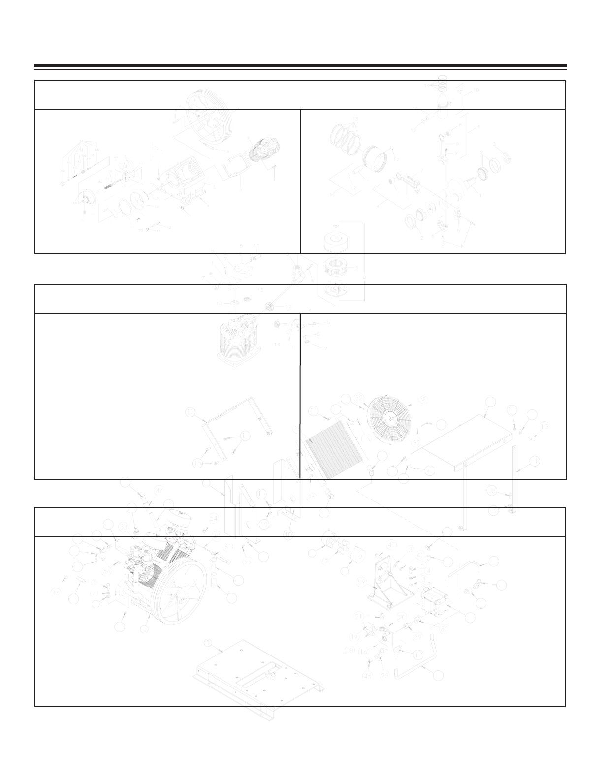
Assembly Drawings
Compressor Assembly
SHD-66DD Manual
12
Page 15

Crankcase, Flywheel, Cylinders, & Centrifugal Unloader
SHD-66DD Manual
13
Page 16

Crankshaft, Rod, & Piston
SHD-66DD Manual
14
Page 17

Valve, Manifold, & Filter
SHD-66DD Manual
15
Page 18

ITEM PART No. DESCRIPTION qty
1 7473 TUBE FITTING 1
2 7474 RELEASE VALVE TUBE W/FITTINGS (ITEMS 1&3) 1
3 7475 TUBE FITTING 1
4 7476 TUBE FITTING 1
5 7477 BREATHER TUBE W/FITTINGS (ITEMS 4&6) 1
6 7476 TUBE FITTING 1
7 7478 TUBE, DISCHARGE 1
8 D1873 INTERCOOLER TUBE W/FTGS RH 1
9 D1872 INTERCOOLER TUBE W/FTGS LH 1
10 5592 TUBE, DISCHARGE 1
11 5593 TUBE FITTING 2
12 7479 PIPE TEE 1
Tubing Assembly
SHD-66DD Manual
16
Page 19

Replacement Parts
HYDRAULIC COMPONENTS/DRIVE PARTS
ART# DESCRIPTION
P
C4914 Relief Valve
C4913 Solenoid Valve
10960 Hydraulic Motor
D0791 Coupling (Hyd Motor)
D0792 Coupling (Compressor)
D0793 Lovejoy Coupling (Blue Urethane
C1129 Oil Cooler
C3075 Aluminum Manifold Block
D1081 Tube Assembly .75 (Return)
D1079 Tube Assembly .50 (Pressure)
C6227 Hydraulic Oil Filter
ELECTRICAL/AIR PRESSURE COMPONENT
PART# DESCRIPTION
C0864 Pressure Switch (Hobbs)
3853 Pilot Valve 145/175 PSI
5480 Check Valve
D0840 Fan 12.00” Push 12 Volt
C5662 Filter Metal Bowl
AIR FILTER COMPONENTS
PART# DESCRIPTION
6073 Intake Filter Assembly
4559 Filter Element (Only)
CHAMPION COMPRESSOR COMPONENTS
PART# DESCRIPTION
D1346 Compressor R30
CENTRIFUGAL UNLOADER COMPONENTS
PART# DESCRIPTION
C0896
7417 Muffler Assembly Unloader
MANIFOLD/VAL
PART# DESCRIPTION
7471 Valve Assembly (Low Pressure Intake)
C0891
7472 Valve Assembly (High Pressure Intake)
C0894 Valve Assembly (High Pressure Exhaust)
4558
4557 Complete Valve Set W/Gaskets
32895 Valve Assembly Kit (Includes PN 7471 And 7472 Only)
ART# DESCRIPTION
P
Release Valve Assembly Kit
VE COMPONENT
Assembly (Low Pressure Exhaust)
alve
V
Complete V
TUBING COMPONENTS
alve Gasket Set
D1873 Intercooler Tube w/Fittings (Right Hand)
D1872 Intercooler Tube w/Fittings (Left Hand)
HYDRAULIC COMPONENTS/DRIVE PARTS
ART#
P
8825 SHD66 Compressor Service Kit
DESCRIPTION
(Includes
Air filters, Hyd Oil Filter
SHD-66DD Manual
17
, and Compressor Oil)
Page 20

Troubleshooting
If symptoms of poor performance develop, the following chart can be used as a guide to investigate
and correct the problem. When diagnosing faults in operations of the air compressor, always check
that the hydraulic power source is supplying the correct hydraulic flow and pressure that is listed in
the compressor specification section of this manual.
olution
Problem
Possible Cause
S
Compressor will not start:
Compressor runs slow or
slows down during
operation:
PTO not engaged.
Emergency brake off.
Blown fuse.
Loose or broken power/ground wire.
Compressor manifold solenoid will not
engage.
Loose air lines or hoses.
Hydraulic flow too low.
Hydraulic motor worn.
Hydraulic relief set too low.
Faulty compressor valves.
Pilot valve leaking air.
Centrifugal unloader valve leaking.
Engage PTO.
Fully engage parking brake.
Replace fuse.
Repair connection.
Repair wiring to coil.
Replace valve.
Tighten air lines and hose connections.
Check and reset flow.
Replace with new motor.
Readjust relief valve.
Clean or replace.
Replace pilot valve.
Remove the governor release valve cap, giving
access to the unloader pressure release valve
spring and ball - Clean thoroughly and
reassembly.
Compressor will lock up
after operating for a short
period:
Compressor runs hot:
Hydraulic oil temp high.
Hydraulic motor drive coupler loose.
Faulty hydraulic relief valve.
Faulty check valve.
Dirty after cooler or intercooler tubing.
Faulty compressor values.
Dirty intake muffler.
Low crankcase oil level.
SHD-66DD Manual
18
Hydraulic fluid low.
Hydraulic reservoir size incorrect.
Reposition and tighten coupler.
Remove relief valve, inspect o-rings and backup
seals or replace relief valve.
Clean or replace check valve.
Remove and clean.
Clean or replace valves.
Clean or replace.
Add compressor oil as needed.
Page 21

Problem
Possible Cause
Solution
Compressor will not shut
down:
Compressor continues to
build air during idle mode:
Compressor will not speed
up when compressor is
activated:
Air line or air hose leaks.
Misadjustment of pilot valve.
ilot valve leaking air
P
entrifugal unloader valve is leaking.
C
Moisture or rust contamination.
Faulty low pressure intake valve.
Leaking or misadjustment of the pilot
valve.
Air reservoir full.
Faulty pressure switch.
No 12 volt power to coil solenoid
valve located on hydraulic manifold.
Tighten air lines or hose connections.
Adjust valve per manual specifications.
lean or replace pilot valve.
C
ee “Compressor runs slowly” section.
S
Remove filter bowl. Fill with WD40 lubricant.
Open air tank valve. Run compressor for 10
minutes. Partially close air tank valve and cycle
compressor. Repeat as needed.
Clean or replace low pressure intake valves.
ighten or adjust valve per manual specs.
T
Drain air from reservoir.
Test for 12 volt power on both the “C” and “NC”
side of the terminals. If no power on “NC” side
of pressure switch, replace switch.
Check fuse. Check ground wires. Check
chassis emergency brake switch.
Engine RPM will not
increase when compressor
is activated:
Compressor cycles or runs
often:
Chassis engine RPM
continue to operate at high
speed when air receiver
reaches maximum capacity:
Loose wiring.
Faulty pressure switch.
Faulty speed control.
Faulty pressure switch.
Excessive water in air reservoir.
Pip lines leaking air.
Misadjustment of pilot valve.
Air leaking from pilot valve.
Check valve leaking.
Faulty pressure switch.
Pressure switch wiring.
Check wiring to : Solenoid valve, pressure
switch, ground wiring.
Replace pressure switch.
Check speed control wiring for loose or broken
connections. Check relay (For ECM operated
speed settings.)
Replace pressure switch.
Drain air reservoir.
Tighten or replace lines.
Adjust valve per manual specifications.
Clean, adjust, or replace.
Clean or replace.
Replace pressure switch.
Wires place on pressure switch incorrectly or
loose ground wire.
SHD-66DD Manual
19
Page 22

Limited Warranty Statement
®
American Eagle warrants products designed and manufactured by Stellar to be free from defects in material and workmanship under proper use
and maintenance. Products must be installed and operated in accordance with Stellar’s written instructions and capacities. The warranty period
shall cover the following:
Twelve (12) month warranty on parts and
Twelve (12) month repair labor
The warranty period shall begin from the date recorded by American Eagle as the in-service date. This date will be derived from the completed
warranty registration card. In the event a warranty registration card is not received by American Eagle, the factory ship date will be used. New
compressors will be issued on all returns within 90 days of this factory ship date. After 90 days, American Eagle reserves the right to issue
remanufactured compressors. Regardless of in-service date, warranty coverage does not extend beyond twenty-four (24) months from date of
manufacture.
American Eagle’s obligation under this warranty is limited to, and the sole remedy for any such defect shall be, the repair and/or replacement (at
American Eagle’s option) of the unaltered part and/or component in question. American Eagle after-sales service personnel must be notified by
telephone, fax, or letter of any warranty-applicable damage within fourteen (14) days of its occurrence. If at all possible, American Eagle will ship
the replacement part within 24-hours of notification by the most economical, yet expedient, means possible. Expedited freight delivery will be at
the expense of the owner
.
Warranty claims must be submitted and shall be processed in accordance with American Eagle’s established warranty claim procedure. American
Eagle after-sales service personnel must be contacted prior to any warranty claim. A return materials authorization (RMA) account number must
be issued to the claiming party prior to the return of any warranty parts. Parts returned without prior authorization will not be recognized for
warranty consideration. All damaged parts must be returned to American Eagle freight prepaid; freight collect returns will be refused. Freight
reimbursement of returned parts will be considered as part of the warranty claim.
Warranty service will be performed by any American Eagle new equipment distributor, or by any American Eagle-recognized service center
authorized to service the type of product involved, or by the American Eagle factory in the event of a direct sale. At the time of requesting
warranty service, the owner must present evidence of date of delivery of the product.
The owner shall be obligated to pay for any overtime labor
requested of the servicing company by the owner, any field service call charges, and any towing and/or transportation charges associated with
moving the equipment to the designated repair/service provider
.
All obligations of American Eagle and its authorized dealers and service providers shall be voided if someone other than an authorized American
Eagle dealer provides other than routine maintenance service without prior written approval from
American Eagle. In the case repair work is
performed on a American Eagle-manufactured product, original American Eagle parts must be used to keep the warranty in force. The warranty
may also be voided if the product is modified or altered in any way not approved, in writing, by American Eagle.
The owner/operator is responsible for furnishing proof of the date of original purchase of the American Eagle product in question. Warranty
registration is the ultimate responsibility of the owner and may be accomplished by the completion and return of the American Eagle product
registration card provided with the product. If the owner is not sure of registration, he is encouraged to contact American Eagle at the address
below to confirm registration of the product in question. This warranty covers only defective material and workmanship. It does not cover
depreciation or damage caused by normal wear and tear
, accident, mishap, untrained operators, or improper or unintended use. The owner has
the obligation of performing routine care and maintenance duties as stated in American Eagle’s written instructions, recommendations, and
specifications. Any damage resulting from owner/operator failure to perform such duties shall void the coverage of this warranty. The owner will
pay the cost of labor and supplies associated with routine maintenance.
The only remedies the owner has in connection with the breach or performance of any warranty on the American Eagle product specified are
those set above. In no event will
American Eagle, the American Eagle distributor/dealer, or any company affiliated with American Eagle be liable
for business interruptions, costs of delay, or for any special, indirect, incidental, or consequential costs or damages. Such costs may include, but
are not limited to, loss of time, loss of revenue, loss of use, wages, salaries, commissions, lodging, meals, towing, hydraulic fluid, or any other
incidental cost.
All products purchased by
American Eagle does not participate in, or obligate itself to, any such warranty
American Eagle from outside vendors shall be covered by the warranty offered by that respective manufacturer only.
.
American Eagle reserves the right to make changes in design or improvement upon its products without imposing upon itself the same upon its
products theretofore manufactured.
This warranty will apply to all
American Eagle Drawer Sets and Compressed Air Systems shipped from American Eagle’s factory after July 1,
2005. The warranty is for the use of the original owner only and is not transferable without prior written permission from American Eagle.
THIS WARRANTY IS EXPRESSLY IN LIEU OF ANY OTHER WARRANTIES, EXPRESS OR IMPLIED, INCLUDING ANY WARRANTY OF
MERCHANTABILITY OR FITNESS FOR A PARTICULAR PURPOSE. REMEDIES UNDER THIS WARRANTY ARE LIMITED TO THE
PROVISION OF MATERIAL AND SERVICES, AS SPECIFIED HEREIN. AMERICAN EAGLE INDUSTRIES, INC. IS NOT RESPONSIBLE FOR
INCIDENTAL OR CONSEQUENTIAL DAMAGES.
Revision Date: March 2006 Document Number: 37042
Page 23

Page 24

 Loading...