

Page 1
®
Owner’s Manual
Safety, Installation, Maintenance, and Operation
Model SHD-245
Subject to Change without Notification.
© 2007 American Eagle
American Eagle, Inc.
190 State Street
PO Box 169
Garner, IA 50438
800-392-3015
Fax: 641-923-4889
www.americaneagleacc.com
Manual Part No. 37244
Last Revision: 4/16/07
Page 2

Introduction
American Eagle Compressors are designed to
provide safe and dependable service for a
variety of operations. With proper use and
maintenance, American Eagle Compressors will
operate at peak performance for many years.
This manual contains information vital to the
safe use and efficient operation of this unit.
Following the information provided within this
manual can ensure the longevity of the
compressor. Carefully read and study the
operator’s manual before using the unit. Failure
to adhere to the instructions could result in
property damage or even serious bodily injury to
the operator or others close to the compressor.
A copy of this manual is provided with every
compressor and shall remain with the
compressor at all times. Information contained
within this manual does not cover all
maintenance, operating, or repair instructions
pertinent to all possible situations. This manual
is not binding. American Eagle reserves the
right to change, at any time, any or all of the
items, components, and parts deemed
necessary for product improvement or
commercial/production purposes. This right is
kept with no requirement or obligation for
immediate mandatory updating of this manual.
This product manual is not intended as a
training manual for beginners or unskilled
operators. This manual offers guidelines for
correct and safe usage of the compressor,
maintenance, and troubleshooting. If more
information is required or technical assistance is
needed, please contact AE Technical Support.
Some sections of this manual contain
information pertaining to all American Eagle
manufactured compressors and may or may not
apply to your specific model.
If this manual becomes damaged, misplaced, or
unreadable at any point, or if you feel that any
part of this manual is unclear or incorrect,
please contact AE Technical Support at 800321-3741 or email at
service@americaneagleacc.com
For Technical Questions, Information, Parts, or Warranty, Call Toll-Free at
800-321-3741
Hours: Monday - Friday, 8:00 a.m. - 5:00 p.m. CST
Or email at the following addresses:
Technical Questions, and Information service@americaneagleacc.com
Order Parts parts@americaneagleacc.com
Warranty Information warranty@americaneagleacc.com
SHD-245 Manual
1
Page 3
Table of Contents
Safety Page 3
Specifications Page 4
Operation Page 5
Head Unloading System Page 6
Maintenance Page 7
Installation Page 8
Assembly Drawings Page 12
Replacement Parts Page 17
Troubleshooting Page 18
Warranty Page 20
SHD-245 Manual
2
Page 4

Safety
This manual contains vital information for the safe use and efficient
operation of this unit. Carefully read the operators manual before
starting the unit. Failure to adhere to the instructions could result in
serious bodily injury or property damage.
The SHD-245 Hydraulic Air Compressor will
provide safe and dependable service if operated
according to instructions. Read and understand
the safety precautions given in this manual and
on the decals attached to the shields. Failure to
do so can result in personal injury or equipment
damage.
Operators and maintenance personnel must
always comply with the safety precautions.
These precautions are given here for your
safety. Review them carefully before operating
the compressor and before performing
maintenance or repairs.
Supervising personnel should develop additional
precautions relating to the specific work area
and local safety regulations.
Precautions
Always wear safety equipment such as goggles,
ear plugs and head protection at all times when
operating the compressor.
Do not inspect or clean the compressor while
the hydraulic power source is connected.
Accidental engagement of the tool can cause
serious injury.
Before performing any maintenance on the
compressor, place a warning tag on the
hydraulic power source or disconnect the hoses
from the compressor motor to prevent
accidental startup of the compressor.
Always connect hoses to the compressor before
energizing the hydraulic power source. Be sure
all hose connections are tight, both air and
hydraulic.
Establish a training program for all operators to
ensure safe operation.
Do not operate the compressor unless
thoroughly trained or under the supervision of
an instructor.
Do not operate the compressor if it is damaged,
improperly adjusted or not completely or
properly assembled.
Never operate the compressor with any of the
guards removed.
Do not attempt to adjust or disable the
compressors air pressure relief valve. This
valve limits the air pressure to 175 PSI.
The surface of the air compressor and the
plumbing between the compressor and the
cooler may reach temperatures above 150
degrees. Touching these surfaces during
operation can cause burns.
The air taken in by the air compressor must be
free of flammable fumes and vapors.
Compressor speed should not exceed 1000
RPM.
Use and operate this air compressor only in full
compliance with all pertinent O.S.H.A.
requirements and all Federal, State and Local
codes or requirements.
SHD-245 Manual
3
Page 5
9
2
Specifications
Drive System Description
• 24 GPM Hydraulic System • 2000 PSI System Pressure
• 2500 PSI Pressure Relief Setting • 12 VDC Solenoid Control Valve
• All Steel Plumbing W/ JIC Fittings • 6061 Aluminum Manifold
• 861 CFM, 12 Volt Cooler Fan • Air Pressure Control Valve
Compressor System Description
• Cast Iron Crankcase Casting
• Gasket-free Integrated Cylinder/Head • Heavy Ductile Iron Crankshaft
• Precision Balanced Flywheel • Pressure Relief Valves in Interstage
• Large Diameter Finned Inner Cooling Tubing • Pressure Lubricated System
• Positive Acting Centrifugal Head Unloaders • Preset Pilot Control Valve
• Tapered Roller Main Bearings
and Discharge
General Information
• Model: Champion R70
• Weight: 900 lbs. (dry)
• Delivery: 110 CFM @ 175 PSI
• Maximum Working Pressure: 175 PSI
• Dimensions: 42”L x 27.5”W x 31”H
• Electrical: 12 VDC @ 10 amp
• Crankcase Oil Capacity: 5 Quart
• Cylinders: Four Cylinder(Single Stage)
• Maximum Compressor Speed: 1000 RPM
SHD-245 Manual
4
Page 6

Operation
Each compressor is bench tested under load at the factory to ensure proper break-in and operation.
While it is not necessary to follow any break-in procedure, the following checks should be made
before putting the unit into service and periodically during use.
Before Start-Up
Inspect unit for any visible signs of damage.
Check the oil level in the compressor with the dipstick on the unit. If oil is needed, use American
Eagle synthetic compressor oil (P/N C0087) or an equivalent synthetic oil.
left in the crankcase from the factory bench test. Overfilling may cause the compressor to
back blow oil. Always check the oil level and fill to the designated marking on the dipstick
before putting the unit into service.
Check hoses (air and hydraulic) for weak or worn condition and make sure that all connections are
secure.
Check the air intake filters on each head to make certain that they are clean and unobstructed.
Dirty air filters are a possible cause of reduced air output.
Note: There may be oil
General Information
To use the compressor, start the vehicle engine
and engage the hydraulic system. The
compressor can now be activated using the
compressor switch. This energizes the hydraulic
solenoid sending oil to the hydraulic drive motor
and starts the compressor. Through the air
pressure switch and pilot valve, the system will
now function automatically
adjust the engine speed control to ensure that
the compressor speed does not exceed 1000
RPM under load. Adjustment instructions are
provided with the speed control unit.
Air Pilot Valve Operation (Head Unloading
System)
When the hydraulic system is engaged the
compressor will pump air into the receiver until
the pressure reaches 175 psi. At this time the
air pilot valve senses the pressure in the
receiver and engages an intake valve hold-open
mechanism. The compressor will run free until
the pressure in the receiver falls below 145 psi
and the air pressure valve disengages the
intake valve hold-open mechanism to allow the
. Once engaged,
compressor to pump air. See head unloading
system for detailed views and adjustment
instructions the following page.
Operating Notes
This reciprocating compressor must not be used
for breathing air. To do so will cause serious
injury whether air is supplied direct from the
compressor source or to breathing tanks for
later use. Any and all liabilities for damage or
loss due to injuries, death and/or property
damage, including consequential damages
stemming from the use of this compressor to
supply breathing air will be disclaimed by the
manufacturer.
The use of this compressor as a booster pump
and/or to compress a medium other than
atmospheric air is strictly non-approved and can
result in equipment damage and/or injury. Nonapproved uses will also void the warranty.
Never use plastic pipe or improperly rated metal
pipe. Improper piping materials can burst and
cause injury or property damage.
SHD-245 Manual
5
Page 7
3
/16" WHEN PISTON IS UP
ITEM PART DESCRIPTION QTY. ITEM PART DESCRIPTION QTY.
1 26804 LOW PRESSURE INTAKE MANIFOLD R70 2 9 0521 WASHER 0.25 LOCK 12
1A 26807 HIGH PRESSURE INTAKE MANIFOLD R70 2 10 7493 GASKET UNLOADER VALVE R70 2
2 7481 CYLINDER UNLOADER VALVE R70 4 11 26821 ACTUATING TUBE R70 1
3 26812 UNLOADER PISTON R70 4 12 26822 MANIFOLD TUBE RB/LB R70 1
4 7483 O'RING UNLOADER VALVE R70 4 13 26823 INTERMEDIATE TUBE R70 1
5 13924 PISTON ROD LP UNLOADER VALVE R70 2 14 7475 TUBE FTG R70 2
5A 13925 PISTON ROD HP UNLOADER VALVE R70 2 15 7498 CPRSN TEE R70 3
6 4567 CLAW UNLOADER VALVE LP R70 2 16 C5568 UNLOADER VALVE CONRADER 1
6A 13921 CLAW UNLOADER VALVE HP R70 2 17 26824 COMPRESSION FITTING R70 1
7 13922 SPRING UNLOADER VALVE LP R70 2 18 C6064 U BOLT 0.25X1.25X2.25 1
7A 13923 SPRING UNLOADER VALVE HP R70 2 19 13735 UNLOADER VALVE ASM LP R70 2
8 1056 NUT 0.25-28 HH 8 20 13736 UNLOADER VALVE ASM HP R70 2
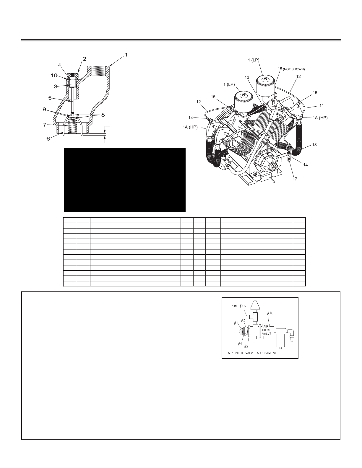
Head Unloading System
CAUTION
When re-installing head unloader the
actuating claw (Ref. No. 6) protrudes 3/16”
below the bottom of the manifold (Ref. No.
1) as shown. Claw must be position so that
it will enter three slots in the compressor
valve. Failure to follow this procedure will
result in an inoperative head unloader.
Air Pilot Valve Adjustment
(See Air Pilot Valve Adjustment Detail)
High Pressure Adjustment: Proceed with the following
while the compressor is running.
1.) Loosen locknut (4) and back off several turns. Do
not turn dif
2.) Check reading on the tank pressure gauge. Set the
compressor maximum pressure at 175 psi. Over
pressurizing compressor will cause damage and void
warranty. Turn threaded cap (1) clockwise to increase
pressure or counterclockwise to decrease pressure.
3.) After pressure is set, tighten locknut
4.) Be careful not to move the threaded cap (1).
Differential Pressure Adjustment: Proceed with the
following while the compressor is running.
ferential adjuster (3).
1.) Loosen locknut (2) and back of
2.) Check reading on the tank pressure gauge. Set the
pressure to 30 psi dif
at 145 psi). Turn nut (3) clockwise to increase
differential pressure or counterclockwise to decrease
dif
3.) After pressure is set, tighten locknut (2). Be careful
not to move nut (3)
SHD-245 Manual
6
ferential (unload at 175 psi, reload
ferential pressure.
f several turns.
Page 8

Maintenance
The following table is a list of routine maintenance items, including service intervals. Service
intervals are listed as hours, days, or weeks, whichever occurs first. American Eagle recommends
that these service intervals be followed. Before performing any maintenance function “Lock Out” or
“Tag Out” all sources of power. Be sure all air pressure in unit is relieved. Failure to do so may
result in injury or equipment damage.
Service Intervals
Maintenance operation Daily Weekly Monthly Hourly
Drain air tanks
Check crankcase oil level
Check fittings and airlines
Check hydraulic fluid level
Inspect and clean air intake filters
Clean and operate safety valves
Clean cooling fins on radiator
Inspect check valve
Inspect and clean compressor valves 6
Replace hydraulic filter 6
Replace air filters 3
Tighten all fittings and fasteners 3
Check all electrical connections 3
Inspect and clean air check valve 250
CHANGE CRANKCASE OIL (see footnote below)
Under normal operating conditions, oil changes are required every 3 months. When operating in a
dirty environment, change the oil more frequently as your particular operating condition dictates.
USE AE SYNTHETIC COMPRESSOR OIL P/N C0087.
COMPRESSOR CRANKCASE CAPACITY IS 5 QUARTS.
General preventative maintenance includes maintaining proper fluid level in both systems and the
general cleanliness of the equipment. Proper fluids according to the specifications are required.
SHD-245 Manual
7
Page 9

Installation
Power
Source
Toggle
Switch
In Cab
Indicator
Light
In Cab
(Recommended)
O
range Wire To
Speed Control
Compressor
Pressure
Switch
Compressor
Cooling Fan
Solenoid
Valve
Fuse
Red
Black
Black
Blue
NO
C
NC
COMPONENT INSTALLATION
This section pertains to the installation of the air compressor, PTO, pump and other related items.
The instructions are intended as a guide to assist you with particular installation. These instructions
will provide only general information.
Pump Assembly:
The pump assembly may either be installed
directly on the PTO or as an optional method,
may be driven by a driveline from the PTO.
Pump manufacturers provide specific installation
information for their products and should be
consulted if questions arise.
PTO Assembly:
Check with the PTO manufactures
representative for specific instructions regarding
your particular make, model, and year of
vehicle. As some trucks may require
modification of the transmission cross member
and the exhaust system, the manufacturer’s
instructions should be followed to insure proper
installation of the PTO.
Compressor Assembly:
Prepare the mounting location of the
compressor by locating and drilling four (4)
holes, 9/16” diameter as per the mounting
pattern of the air compressor base. Using four
(4) 1/2” x 1.50 GR-5 cap screws,1/2” flat
washer, and 1/2” nyloc nut, secure the
compressor in place. The compressor is air
cooled, and must have a clean supply of cooling
air to the fan with minimum restrictions.
Adequate space must be provided for proper
circulation of air.
a toggle switch in a convenient location.
Connect one terminal to the compressor
pressure switch and the other terminal to a 12volt power supply. Add a 20 amp fuse between
the battery and switch. A third wire is required
from the air compressor pressure switch when
connecting the speed control into the system.
(See drawing below)
Electric speed control:
An optional electric or electronic speed control
must be used to maintain proper operating
speed of the air compressor. The engine speed
control will automatically increase from idle to a
preset speed when engaged and decrease
when disengaged. The electric speed control
(American Eagle P/N C0873) is used on most
gasoline engines. The electronic speed controls
are used only on Ford 6.0 and 7.3L diesel
engines. Proper installation instructions are
provided with each system.
Electrical Connections:
From the solenoid valve (located on the
hydraulic manifold) there are two (2) wires, red
and black, running to the compressor pressure
switch. Connect the black wire to the vehicle
frame or other suitable ground. The red wire
mounts to the pressure switch as shown. Install
SHD-245 Manual
8
Page 10

3/4" RETURN LINE
T
O RESERVOIR
M
OTOR CASE DRAIN
ROUTED TO HYDRAULIC
R
ESERVOIR
3/4" HIGH PRESSURE
HYDRAULIC HOSE
L
ENGTH AS REQUIRED
NC
C
NO
DETAIL A
DETAIL B
1/4" HOSE
AIR SENSE LINE
TO AIR TANK
CHECK VALVE MUST
BE PLACED
BETWEEN AIR
DELIVERY LINE AND
TANK
SEE DETAIL A
SEE DETAIL B
Component Installation Continued...
Hydraulic System:
Installed on the compressor is a valve block assembly that controls the flow to the hydraulic
motor. To this block, a 3/4” high-pressure hose and a 3/4” return line must be attached. (See
drawing above) Note: The case drain line from the hydraulic motor is also routed to the oil
reservoir
the proper suction and return filters. The cooler on the compressor is designed and sized to
cool the air compressor efficiently. An auxillary oil cooler is required when additional
hydraulically operated equipment are added to the hydraulic system. Pressure on the return
line exceeding 200 PSI can and will cause damage to the filter, cooler, and components of the
compressor hydraulic system.
. American Eagle recommends a sufficient sized reservoir be provided which includes
Air System:
Two (2) airlines must be routed to the air tank for
proper installation. The main airline is routed from
the check valve to the air tank using a 3/4”(200psi)
air hose. This is the main delivery line and should
be free from all obstructions. A 1/4” line is routed
from the air pressure valve to the air tank. This line
senses the pressure in the tank and will engage
and disengage the compressor automatically.
SHD-245 Manual
9
Page 11

PN 30533
PN 30532
Typical Hydraulic Circuit for Single Stage Pump with
Multiple Components
Typical Hydraulic Circuit for Tandum (Two Part) Pump with
Multiple Components
SHD-245 Manual
10
Page 12

Typical Hydraulic Circuit for Compressor
COMPRESSOR
RETURN
PRESSURE
AUXILIARY
COOLER
SINGLE
HYDRAULIC
PUMP
SUCTION PORT
FILTER
FILTER SCREEN
HYDRAULIC
RESERVOIR
with Auxiliary Cooler
SHD-245 Manual
11
Page 13

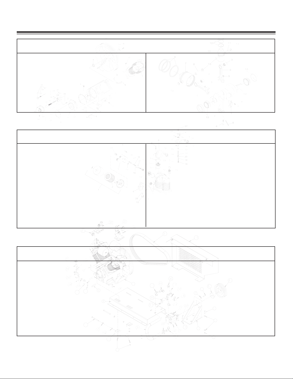
Assembly Drawings
8
04
91
7
1
3
2
02
2
5
2
6
2
5
4
2
72
82
93
03
9
1
33
7
43
6
23
13
53
51
7
4
6
3
8
61
8
1
8
7
5
1
0
1
3
1
5
1
1
1
21
41
6
7
12
22
5
3
6
3
73
83
7
1
4
.Y
TQNOITPIRCSEDT
RAPMET
I
1TM POT 07R/
04R TM
DLW ESAB246
01
1
1ROSSERPMOC UH-A07R N
O
I
PMAHC9801C
2
1RSRPC TNUOM ROTOM DYH TKRB9710B3
123-51AZLPS137A0003
M
D
YH ROTOM07544
25RGHH 05.2X31-05.0 RCS PAC20505
2
1
COL
YN 5R
GHH 31-05.0 TUN6016C6
228RG TALF 05
.0 REH
SAW0970D7
015RGHH 00.2X31-05.0 RCS PAC10508
1SSARB 00.4X83.0
ELPPIN65402
9
166 DHS RSRPC LA KCOLB5703C01
1
D
NLOS EVLAV3194C11
1
C-A-0-B-1-002-PC FEILER EVLAV4194C21
1N
O5P-21 GULP 5
7.0 GT
F51
06C
31
1
S
-XO5F-2
1 TNNO
C TR
TS C
IJ/BRO G
TF9455C41
.YTQNOITPIRCSEDT
RAPMET
I
321-02-1064 RTSM/BRAB 09 GTF2900251
1K
S49 B3 EVOORG 3 EVAEHS YELLUP3031D
6
1
2SSARB GED 09 52.1 LE TS36402
71
100.1 G
NIHSUB8816C
81
1)3-09PBR OCYAD( SETAG 09B3 TLEB652991
2RSRPC 07R TFEL EKATNI8671102
1LLE LM 52.0 GT
F8095C
12
1TPNM 52. X ESOH 83. BRAB ESOH GTF5722C22
2
SSARB DH
QS TPN 52.1
GULP52822
32
1DD66DHS TNM EVLAV REDAOLNU TKRB307442
1LPS TPNF 521.0/TPNM 52.0 L TS GTF77285
2
1SBBOH SERP HCT
IWS4680C
62
1ELPPIN XEH FF 52.0-83.0 GTF0330272
152.0 LW
OB LA
TEM RETLIF2665C82
.YTQNOITPIRCSEDTRAPMETI
1SSARB GED
09 5
2.0 LE TS8145
92
1TPNM 52. X ESOH 52.
B
R
AB ESOH GTF4722C03
100.03X52.1 NOITCUS ESOH6746213
2TMDLW RSRP
C REN
ETHGIT ELGN
A3480B23
25RG DAERHT LLA 00.6X31-05.0 RCS PAC796833
2HH 31-05.0 TUN735043
202-BD 88 PMALC ESOH3211C53
1S-LCR ISP 571/541 TOLIP EVLAV358363
152.2X52.1X5
2.0 TL
OB
U4606C73
2SSARB DH QS TPN 52.0 GULP6230283
1S-OLO5C 21-8 09 RTSM/FM GTF869
5C93
1542-DHS TIK REVOC7008204
Compressor Assembly
SHD-245 Manual
12
Page 14

ITEMPART DESCRIPTION QTY. ITEMPART DESCRIPTION QTY.
1 26490 CRANKCASE R-70 1 21 26782 CAP SCR 0.44-20X1.25 HHGR5 4
2 20326 PLUG 0.25 NPT SQ HD BRASS 1 22 26783 CAP SCR 0.44-20X1.00 HHGR5 2
3 26491 OIL SEAL R70 1 23 26778 GOVERNOR BAFFLE PLATE R70 1
4 C4845 PLUG 0.75 NPT SQ HD BLK 1 24 6096 SPINDLE GOV WEIGHT R30/R70 1
5 20456 NIPPLE 0.38X4.00 BRASS 1 25 6097 GOVERNOR WEIGHT R30/R70 2
6 D1254 CAP 0.38 PIPE HEX 5406-6 1 26 6098 PIN GOV WEIGHT R30/R70 2
7 4561 OIL LEVEL GAUGE RE714 1 27 0524 WASHER 0.44 LOCK 1
8 26493 CYLINDER FLANGE GASKET R70 2 28 26782 CAP SCR 0.44-20X1.25 HHGR5 1
9 26494 CYLINDER R70 2 29 0343 WASHER 0.31 USS FLAT ZINC 1
10 0359 CAP SCR 0.50-13X1.50 HHGR5 12 30 7414 SPRING GOV MAIN R30/R70 1
11 26495 FLYWHEEL R70 1 31 7415 SLEEVE SPRING R30/R70 1
12 26780 MACHINERY KEY R70 1 32 6094 GASKET GOV HSG COVER R30/R70 1
13 26496 FLYWHEEL RETAINER WASHER R70 1 33 26779 GOVERNOR HOUSING COVER R70 1
14 26781 CAP SCR 0.44-20X2.00 HHGR5 1 34 17246 MUFFLER ASM UNLOADER R15/R70 1
15 26497 GOVERNOR HOUSING GASKET R70 1 35 26784 CAP SCR #10-32X0.63 HHGR5 6
16 26498 GASKET 0.031 R70 1 36 C089
6
VALVE KIT REL 1
17 26499 GASKET 0.015 R70 1 37 7419 PLUNGER RELEASE VALVE R30/R70 1
18 26500 GASKET 0.010 R70 1 38 7423 BALL RELEASE VALVE R30/R70 1
19 26776 GASKET 0.006 R70 1 39 7424 SPRING RELEASE VALVE R30/R70 1
20 26777 GOVERNOR HOUSING R70 1 40 17248 BODY RELEASE VALVE R15/R70 1
Crankcase, Flywheel, Cylinders, & Centrifugal Unloader
SHD-245 Manual
13
Page 15

ITEM PART DESCRIPTION QTY. ITEM PART DESCRIPTION QTY.
1 26785 LP CONNECTING ROD ASM R70 2 10 26794 HP PRESSURE PISTON W/PIN R70 2
2 26786 HP CONNECTING ROD ASM R70 2 11 26795 HP PRESSURE PISTON PIN R70 2
3 26787 PISTON PIN BEARING R70 4 12 26796 HP PRESSURE PISTON RING SET R
7
2
4 26788 CONNECTING ROD BOLT R70 8 13 26797 PISTON PIN RETAINING RING R70 8
5 26789 CONNECTING ROD NUT R70 8 14 26798 CRANKSHAFT R70 1
6 26790 OIL DIPPER HP ONLY R70 2 15 26799 MAIN BEARING R70 2
7 26791 LP PISTON W/PIN R70 2 16 26800 PUMP RING SET R70 1
8 26792 LP PISTON PIN R70 2 17 26801 LP PISTON ASM R70 2
9 26793 LP PISTON PIN RING SET R70 2 18 26802 HP PISTON ASM R70 2
Crankshaft, Rod, & Piston
SHD-245 Manual
14
Page 16

ITEM PART DESCRIPTION QTY. ITEM PART DESCRIPTION QTY.
126803 FILTER ASM R70 2 16 13923 SPRING UNLOADER VALVE HP R70 2
24562 FILTER ELEMENT R70 2 17 13922 SPRING UNLOADER VALVE LP R70 2
326804 LOW PRESSURE INTAKE MANIFOLD R70 2 18 1056 NUT 0.25-28 HH 8
426805 HIGH PRESSURE EXHAUST MANIFOLD R70 2 19 0521 WASHER 0.25 LOCK 8
526806 LOW PRESSURE EXHAUST MANIFOLD R70 2 20 13921 CLAW UNLOADER VALVE HP R70 2
626807 HIGH PRESSURE INTAKE MANIFOLD R70 2 21 4567 CLAW UNLOADER VALVE LP R70 2
7 C1182 VALVE PRESS RELIEF CHAMP 2 22 13925 PISTON ROD HP UNLOADER VALVE R70 2
80494 CAP SCR 0.44-14X2.00 HHGR5 16 23 13924 PISTON ROD LP UNLOADER VALVE R70 2
926808 LOW PRESSURE VALVE GASKET R70 6 24 26812 UNLOADER PISTON R70 4
10 26809 HIGH PRESSURE VALVE GASKET R70 8 25 7483 O'RING UNLOADER VALVE R70 4
11 13731 VALVE ASM LP INTAKE R70 2 26 7493 GASKET UNLOADER VALVE R70 2
12 13734 VALVE ASM HP EXHAUST R70 2 27 7481 CYLINDER UNLOADER VALVE R70 4
13 13733 VALVE ASM HP INTAKE R70 2 28 26811 COMPRESSION FERRULE R70 6
14 13732 VALVE ASM LP EXHAUST R70 2 29 4565 VALVE SET W/GASKETS (R70) Z614 1
15 26810 COMPRESSION NUT R70 6 30 4566 GASKET SET VALVE Z615 1
Valve, Manifold, & Filter
SHD-245 Manual
15
Page 17

ITEM PART DESCRIPTION QTY. ITEM PART DESCRIPTION QTY.
1 26813 BREATHER TUBE 0.38X20.00 W/FITTINGS R70 1 9 26817 RIGHT DISCHARGE TUBE W/FITTINGS R70 1
27476TUBE FTG R70 2 10 26818 LEFT DISCHARGE TUBE W/FITTINGS R70 1
3 26814 UNLOADER VALVE TUBE W/FITTINGS R70 1 11 26819 TEE DISCHARGE TUBE R70 1
47473TUBE FTG R70 1 12 26810 COMPRESSION NUT R70 4
5 26815 INTERCOOLER TUBE W/FITTING LB R70 1 13 26811 COMPRESSION FERRULE R70 1
6 26816 INTERCOOLER TUBE W/FITTING RB R70 1 14 C1183 VALVE PRESS RELIEF CHAMP PO9704A 1
7 26810 COMPRESSION NUT R70 4 15 26820 STRAIGHT COMPRESSION FITTING R70 1
8 26811 COMPRESSION FERRULE R70 4
Tubing Assembly
SHD-245 Manual
16
Page 18

Replacement Parts
HYDRAULIC COMPONENTS/DRIVE PARTS
PART# DESCRIPTION
C4914 Relief Valve
C4913 Solenoid Valve
570 Hydraulic Motor
4
C6188 Bushing 1.00” Pulley
D1303 Sheave Pulley
9256 Belt 3B90 Gates
26476 Suction Line (Motor to Hydraulic Manifold)
C3075 Aluminum Manifold Block
C6225 Hydraulic Oil Filter
ELECTRICAL/AIR PRESSURE COMPONENT
PART# DESCRIPTION
C0864 Pressure Switch (Hobbs)
3853 Pilot Valve 145/175 PSI
C5662 Filter Metal Bowl
AIR FILTER COMPONENTS/SERVICE KIT
PART# DESCRIPTION
26803 Filter Assembly R70
4562 Filter Element (Only)
32893 SHD245 Service Kit
(Includes Air Filters, Hyd Oil Filter, Compressor Oil)
CHAMPION COMPRESSOR COMPONENTS
PART# DESCRIPTION
C1089 Compressor R70
CENTRIFUGAL UNLOADER COMPONENTS
PART# DESCRIPTION
C0896 Release Valve Assembly Kit
17246 Muffler Assembly W/Unloader
MANIFOLD/VALVE COMPONENT
ART#
P
13731 Valve Assembly (Low Pressure Intake)
13732 Valve Assembly (Low Pressure Exhaust)
13733 V
13734 Valve Assembly (Height Pressure Exhaust)
4566 Complete Valve Gasket Set
4565 Complete Valve Set W/Gaskets
7481 Cylinder - Unloader Valve
7493 Gasket - Unloader Valve
C1182 Pressure Relief Valve
ART#
P
DESCRIPTION
alve Assembly (High Pressure Intake)
TUBING COMPONENTS
DESCRIPTION
26815 Intercooler Tube w/Fittings (Left Bank)
26816 Intercooler Tube w/Fittings (Right Bank)
C1183 Pressure Relief Valve
SHD-245 Manual
17
Page 19

Troubleshooting
If symptoms of poor performance develop, the following chart can be used as a guide to investigate
and correct the problem. When diagnosing faults in operations of the air compressor, always check
that the hydraulic power source is supplying the correct hydraulic flow and pressure that is listed in
the compressor specification section of this manual.
olution
Problem
Possible Cause
S
Compressor will not start:
Compressor runs slow or
slows down during
operation:
PTO not engaged.
Emergency brake off.
Blown fuse.
Loose or broken power/ground wire.
Compressor manifold solenoid will not
engage.
Loose air lines or hoses.
Hydraulic flow too low.
Hydraulic motor worn.
Hydraulic relief set too low.
Faulty compressor valves.
Pilot valve leaking air.
Centrifugal unloader valve leaking.
Engage PTO.
Fully engage parking brake.
Replace fuse.
Repair connection.
Repair wiring to coil.
Replace valve.
Tighten air lines and hose connections.
Check and reset flow.
Replace with new motor.
Readjust relief valve.
Clean or replace.
Replace pilot valve.
Remove the governor release valve cap, giving
access to the unloader pressure release valve
spring and ball - Clean thoroughly and
reassembly.
Compressor will lock up
after operating for a short
period:
Compressor runs hot:
Hydraulic oil temp high.
Hydraulic motor drive coupler loose.
Faulty hydraulic relief valve.
Faulty check valve.
Dirty after cooler or intercooler tubing.
Faulty compressor values.
Dirty intake muffler.
Low crankcase oil level.
SHD-245 Manual
18
Hydraulic fluid low.
Hydraulic reservoir size incorrect.
Reposition and tighten coupler.
Remove relief valve, inspect o-rings and backup
seals or replace relief valve.
Clean or replace check valve.
Remove and clean.
Clean or replace valves.
Clean or replace.
Add compressor oil as needed.
Page 20

Problem
Possible Cause
Solution
Compressor will not shut
down:
Compressor continues to
build air during idle mode:
Compressor will not speed
up when compressor is
activated:
Air line or air hose leaks.
Misadjustment of pilot valve.
ilot valve leaking air
P
entrifugal unloader valve is leaking.
C
Moisture or rust contamination.
Faulty low pressure intake valve.
Leaking or misadjustment of the pilot
valve.
Air reservoir full.
Faulty pressure switch.
No 12 volt power to coil solenoid
valve located on hydraulic manifold.
Tighten air lines or hose connections.
Adjust valve per manual specifications.
lean or replace pilot valve.
C
ee “Compressor runs slowly” section.
S
Remove filter bowl. Fill with WD40 lubricant.
Open air tank valve. Run compressor for 10
minutes. Partially close air tank valve and cycle
compressor. Repeat as needed.
Clean or replace low pressure intake valves.
ighten or adjust valve per manual specs.
T
Drain air from reservoir.
Test for 12 volt power on both the “C” and “NC”
side of the terminals. If no power on “NC” side
of pressure switch, replace switch.
Check fuse. Check ground wires. Check
chassis emergency brake switch.
Engine RPM will not
increase when compressor
is activated:
Compressor cycles or runs
often:
Chassis engine RPM
continue to operate at high
speed when air receiver
reaches maximum capacity:
Loose wiring.
Faulty pressure switch.
Faulty speed control.
Faulty pressure switch.
Excessive water in air reservoir.
Pip lines leaking air.
Misadjustment of pilot valve.
Air leaking from pilot valve.
Check valve leaking.
Faulty pressure switch.
Pressure switch wiring.
Check wiring to : Solenoid valve, pressure
switch, ground wiring.
Replace pressure switch.
Check speed control wiring for loose or broken
connections. Check relay (For ECM operated
speed settings.)
Replace pressure switch.
Drain air reservoir.
Tighten or replace lines.
Adjust valve per manual specifications.
Clean, adjust, or replace.
Clean or replace.
Replace pressure switch.
Wires place on pressure switch incorrectly or
loose ground wire.
SHD-245 Manual
19
Page 21

Limited Warranty Statement
®
American Eagle warrants products designed and manufactured by Stellar to be free from defects in material and workmanship under proper use
and maintenance. Products must be installed and operated in accordance with Stellar’s written instructions and capacities. The warranty period
shall cover the following:
Twelve (12) month warranty on parts and
Twelve (12) month repair labor
The warranty period shall begin from the date recorded by American Eagle as the in-service date. This date will be derived from the completed
warranty registration card. In the event a warranty registration card is not received by American Eagle, the factory ship date will be used. New
compressors will be issued on all returns within 90 days of this factory ship date. After 90 days, American Eagle reserves the right to issue
remanufactured compressors. Regardless of in-service date, warranty coverage does not extend beyond twenty-four (24) months from date of
manufacture.
American Eagle’s obligation under this warranty is limited to, and the sole remedy for any such defect shall be, the repair and/or replacement (at
American Eagle’s option) of the unaltered part and/or component in question. American Eagle after-sales service personnel must be notified by
telephone, fax, or letter of any warranty-applicable damage within fourteen (14) days of its occurrence. If at all possible, American Eagle will ship
the replacement part within 24-hours of notification by the most economical, yet expedient, means possible. Expedited freight delivery will be at
the expense of the owner
.
Warranty claims must be submitted and shall be processed in accordance with American Eagle’s established warranty claim procedure. American
Eagle after-sales service personnel must be contacted prior to any warranty claim. A return materials authorization (RMA) account number must
be issued to the claiming party prior to the return of any warranty parts. Parts returned without prior authorization will not be recognized for
warranty consideration. All damaged parts must be returned to American Eagle freight prepaid; freight collect returns will be refused. Freight
reimbursement of returned parts will be considered as part of the warranty claim.
Warranty service will be performed by any American Eagle new equipment distributor, or by any American Eagle-recognized service center
authorized to service the type of product involved, or by the American Eagle factory in the event of a direct sale. At the time of requesting
warranty service, the owner must present evidence of date of delivery of the product.
The owner shall be obligated to pay for any overtime labor
requested of the servicing company by the owner, any field service call charges, and any towing and/or transportation charges associated with
moving the equipment to the designated repair/service provider
.
All obligations of American Eagle and its authorized dealers and service providers shall be voided if someone other than an authorized American
Eagle dealer provides other than routine maintenance service without prior written approval from
American Eagle. In the case repair work is
performed on a American Eagle-manufactured product, original American Eagle parts must be used to keep the warranty in force. The warranty
may also be voided if the product is modified or altered in any way not approved, in writing, by American Eagle.
The owner/operator is responsible for furnishing proof of the date of original purchase of the American Eagle product in question. Warranty
registration is the ultimate responsibility of the owner and may be accomplished by the completion and return of the American Eagle product
registration card provided with the product. If the owner is not sure of registration, he is encouraged to contact American Eagle at the address
below to confirm registration of the product in question. This warranty covers only defective material and workmanship. It does not cover
depreciation or damage caused by normal wear and tear
, accident, mishap, untrained operators, or improper or unintended use. The owner has
the obligation of performing routine care and maintenance duties as stated in American Eagle’s written instructions, recommendations, and
specifications. Any damage resulting from owner/operator failure to perform such duties shall void the coverage of this warranty. The owner will
pay the cost of labor and supplies associated with routine maintenance.
The only remedies the owner has in connection with the breach or performance of any warranty on the American Eagle product specified are
those set above. In no event will
American Eagle, the American Eagle distributor/dealer, or any company affiliated with American Eagle be liable
for business interruptions, costs of delay, or for any special, indirect, incidental, or consequential costs or damages. Such costs may include, but
are not limited to, loss of time, loss of revenue, loss of use, wages, salaries, commissions, lodging, meals, towing, hydraulic fluid, or any other
incidental cost.
All products purchased by
American Eagle does not participate in, or obligate itself to, any such warranty
American Eagle from outside vendors shall be covered by the warranty offered by that respective manufacturer only.
.
American Eagle reserves the right to make changes in design or improvement upon its products without imposing upon itself the same upon its
products theretofore manufactured.
This warranty will apply to all
American Eagle Drawer Sets and Compressed Air Systems shipped from American Eagle’s factory after July 1,
2005. The warranty is for the use of the original owner only and is not transferable without prior written permission from American Eagle.
THIS WARRANTY IS EXPRESSLY IN LIEU OF ANY OTHER WARRANTIES, EXPRESS OR IMPLIED, INCLUDING ANY WARRANTY OF
MERCHANTABILITY OR FITNESS FOR A PARTICULAR PURPOSE. REMEDIES UNDER THIS WARRANTY ARE LIMITED TO THE
PROVISION OF MATERIAL AND SERVICES, AS SPECIFIED HEREIN. AMERICAN EAGLE INDUSTRIES, INC. IS NOT RESPONSIBLE FOR
INCIDENTAL OR CONSEQUENTIAL DAMAGES.
Revision Date: March 2006 Document Number: 37042
Page 22

Page 23

 Loading...