

Page 1
OWNER’S MANUAL
Safety, Installation, Maintenance, and Operation
9000 Articulating Crane
Subject to Change without Notification.
© 2007 Stellar Industries, Inc.
Stellar Industries, Inc.
190 State Street
PO Box 169
Garner, IA 50438
800-321-3741
Fax: 641-923-2811
www.stellarindustries.com
Manual Part No. 37811
Last Revision: 4/30/07
Page 2

9000 Manual Revisions
Date of Revision Description of RevisionSection Revised
Page 3

Table of Contents i
Table of Contents
Introduction . . . . . . . . . . . . . . . . . . . . . . . . . . . . . . . . . . . . . . . . . . . ii
Chapter 1 - Safety . . . . . . . . . . . . . . . . . . . . . . . . . . . . . . . . . . . . . 1
Chapter 2 - Operation . . . . . . . . . . . . . . . . . . . . . . . . . . . . . . . . . . 3
Unit Operation Overview . . . . . . . . . . . . . . . . . . . . . . . . . . . . . 3
Radio Remote Operation . . . . . . . . . . . . . . . . . . . . . . . . . . . . . 4
Crane Precautions. . . . . . . . . . . . . . . . . . . . . . . . . . . . . . . . . . . 5
Manual Operation. . . . . . . . . . . . . . . . . . . . . . . . . . . . . . . . . . . 4
Hook Precautions. . . . . . . . . . . . . . . . . . . . . . . . . . . . . . . . . . . . 5
Crane Transport . . . . . . . . . . . . . . . . . . . . . . . . . . . . . . . . . . . . . 5
Operator Information . . . . . . . . . . . . . . . . . . . . . . . . . . . . . . . . 6
Chapter 3 - Maintenance . . . . . . . . . . . . . . . . . . . . . . . . . . . . . . . 7
Lubrication Recommendations . . . . . . . . . . . . . . . . . . . . . . . . 9
Torque Data Chart. . . . . . . . . . . . . . . . . . . . . . . . . . . . . . . . . . 10
Inspection Checklist . . . . . . . . . . . . . . . . . . . . . . . . . . . . . . . . 11
Daily Inspection . . . . . . . . . . . . . . . . . . . . . . . . . . . . . . . . . . 12
Monthly Inspection . . . . . . . . . . . . . . . . . . . . . . . . . . . . . . . 13
Quarterly Inspection . . . . . . . . . . . . . . . . . . . . . . . . . . . . . . 14
Annual Inspection . . . . . . . . . . . . . . . . . . . . . . . . . . . . . . . . 16
Inspection Notes . . . . . . . . . . . . . . . . . . . . . . . . . . . . . . . . .
Chapter 4 - Specifications . . . . . . . . . . . . . . . . . . . . . . . . . . . . . 19
Capacity Chart - Decal PN 29559. . . . . . . . . . . . . . . . . . . . . 20
Chapter 5 - Decals. . . . . . . . . . . . . . . . . . . . . . . . . . . . . . . . . . . . 21
Decals of Note . . . . . . . . . . . . . . . . . . . . . . . . . . . . . . . . . . . . . 21
Crane Cover Decals . . . . . . . . . . . . . . . . . . . . . . . . . . . . . . . . 22
Crane Base Decals . . . . . . . . . . . . . . . . . . . . . . . . . . . . . . . . . 23
Outrigger Decals . . . . . . . . . . . . . . . . . . . . . . . . . . . . . . . . . . . 24
Decal Kit Placement Kit 30488 . . . . . . . . . . . . . . . . . . . . . . . . 25
Chapter 6 - Installation . . . . . . . . . . . . . . . . . . . . . . . . . . . . . . . . 27
General Installation . . . . . . . . . . . . . . . . . . . . . . . . . . . . . . . . . 27
Installation Notice . . . . . . . . . . . . . . . . . . . . . . . . . . . . . . . . . . 27
Installation Overview . . . . . . . . . . . . . . . . . . . . . . . . . . . . . . . . 27
Chapter 7 - Assembly Drawings. . . . . . . . . . . . . . . . . . . . . . . . . 29
Base Assembly - PN 29349 . . . . . . . . . . . . . . . . . . . . . . . . . . . 29
Mast Assembly - PN 29350 . . . . . . . . . . . . . . . . . . . . . . . . . . . 30
Main Boom Assembly - PN 29354. . . . . . . . . . . . . . . . . . . . . . 31
Extension Boom Assembly - PN 29359 . . . . . . . . . . . . . . . . . . 32
Chapter 8 - Hydraulics - Electrical. . . . . . . . . . . . . . . . . . . . . . . 33
Control Kit - PN 29556 . . . . . . . . . . . . . . . . . . . . . . . . . . . . . . . 34
Hydraulic Kit - PN 29557
Chapter 9 - Replacement Parts . . . . . . . . . . . . . . . . . . . . . . . . . 37
Chapter 10 - Troubleshooting
Omnex Diagnostics and Troubleshooting
Warrany Information. . . . . . . . . . . . . . . . . . . . . . . . . . . . . . . . . . . 47
. . . . . . . . . . . . . . . . . . . . . . . . . . . . .
. . . . . . . . . . . . . . . . . . . . . . . . . . .
. . . . . . . . . . . . . . . 41
17
35
39
Page 4

ii 9000 Owner’s Manual
Introduction
Stellar Cranes are designed to provide safe
and dependable service for a variety of
operations. With proper use and
maintenance, these cranes will operate at
peak performance for many years.
To promote this longevity, carefully study the
information contained in this manual before
putting the equipment into service. Though
it is not intended to be a training manual for
beginners, this manual should provide solid
guidelines for the safe and proper usage of
the crane.
Once you feel comfortable with the
material contained in this manual, strive to
exercise your knowledge as you safely
operate and maintain the crane. This
process is vital to the proper use of the unit.
A few notes on this manual:
A copy of this manual is provided with every
crane and shall remain with the crane at all
times. Information contained within this
manual does not cover all maintenance,
operating, or repair instructions pertinent to
all possible situations.
Please be aware that some sections of this
manual contain information pertaining to
Stellar manufactured cranes in general and
may or may not apply to your specific
model.
This manual is not binding. Stellar Industries,
Inc. reserves the right to change, at any
time, any or all of the items, components,
and parts deemed necessary for product
improvement or commercial/production
purposes. This right is kept with no
requirement or obligation for immediate
mandatory updating of this manual.
In closing:
If more information is required or technical
assistance is needed, or if you feel that any
part of this manual is unclear or incorrect,
please contact the Stellar Customer Service
Department by phone at 800-321-3741 or
email at service@stellarindustries.com.
ATTENTION
Failure to adhere to the
instructions could result in
property damage or even serious
bodily injury to the operator or
others close to the crane.
For Technical Questions, Information, Parts, or Warranty, Call Toll-Free at
800-321-3741
Hours: Monday - Friday, 8:00 a.m. - 5:00 p.m. CST
Or email at the following addresses:
Technical Questions, and Information service@stellarindustries.com
Order Parts parts@stellarindustries.com
Warranty Information warranty@stellarindustries.com
Page 5

Chapter 1 - Safety
Safety 1
Please Read the Following Carefully! This portion of
the manual contains information regarding all
Stellar manufactured cranes. Some items
contained within this chapter may not apply to your
specific equipment.
Safety should be the number one thought on every
operator’s mind. Three factors should exist for safe
operation: a qualified operator, well-maintained
equipment, and the proper use of this equipment.
The following information should be read and
understood completely by everyone working with
or near the crane before putting the unit into
operation.
Please take note that Stellar Industries, Inc. is not
liable for accidents incurred by the crane because
of non-fulfillment from the operator’s side of current
rules, laws, and regulations.
GENERAL
It is the responsibility of the owner to instruct the
operator in the safe operation of your equipment
and to provide the operator with properly
maintained equipment.
Trainees or untrained persons shall be under the
direct supervision of qualified persons.
Do not operate equipment under the adverse
influence of alcohol, drugs, or medication.
Do not use controls and hoses as handholds. These
parts move and cannot provide stable support.
Never allow anyone to ride the crane hook or load.
MAINTENANCE SAFETY
Never modify or alter any of the equipment, whether
mechanical, electrical, or hydraulic, without explicit
approval from Stellar Industries.
Do not perform any maintenance or repair work on
the crane unless authorized and trained to do so.
Release system pressure before attempting to make
any adjustments or repairs.
Do not attempt service or r
engaged.
Failure to correctly plumb and wire the crane can
cause a malfunction and damage to the crane
and/or operator.
Decals are considered safety equipment. They must
be maintained, as would other safety devices. Do
not remove any Decals. Replace any Decals that
are missing, damaged, or not legible.
The safety instruction plates, notices, load charts and
any other sticker applied to the crane or service
body must be kept legible and in good condition. If
necessary, replace them.
epair when the PTO is
PERSONAL SAFETY
Keep clear of all moving parts.
Always wear the prescribed personal safety devices.
Always wear approved accident-prevention clothing
such as: protective helmets, anti-slip shoes with steel
toes, protective gloves, anti-noise headphones,
protective glasses, and reflective jackets with
breathing apparatus. Consult your employer
regarding current safety regulations and accidentprevention equipment.
Do not wear rings, wristwatch, jewelry, loose-fitting or
hanging clothing such as ties, torn garments, scarves,
unbuttoned jackets or unzipped overalls, which could
get caught up in the moving parts of the crane.
Keep a first-aid box and a fir
available on the truck. Regularly check to make sur
e extinguisher is fully char
the fir
kit is stocked.
e extinguisher r
ged and the first-aid
eadily
STABILITY
Know the crane components and their capabilities
and limitations. Overloading the crane may result in
serious injury to self and others, and damage to the
equipment and immediate surroundings.
Never exceed manufacturer’s load ratings. These
ratings ar
mechanical, and structural design rather than
stability.
The supporting surface under the service truck must
be able to support the weight of the machine and its
load. Use outrigger pads if necessary.
Park the vehicle on level ground and extend the
outriggers fully out and then down.
Keep feet and legs clear when lowering outrigger
jacks.
e
Never operate the crane without making sur
outriggers are positioned on stable, flat ground.
e based on the machine’s hydraulic,
e the
Page 6
2 9000 Owner’s Manual
Set the parking brake and disengage the drive axle
efore attempting a lift.
b
LOAD SAFETY
Operate the crane in compliance with the load
capacity chart at all times. Know the weight of the
oad being lifted. Do not rely on the overload device
l
to determine maximum rated loads.
Never use a sling bar or anything larger than the
hook throat that could prevent the hook latch from
closing. This would negate the safety feature.
Do not apply side loads to the booms.
Do not leave a crane load suspended or
unattended.
Do not walk under suspended loads.
Do not position any load over a person nor should
any person be permitted to place him or herself
under a load.
Do not use the boom or the winch to drag a load.
Crane Controls
1. Be familiar with the sequence and operation of
the crane controls.
Do not use the crane boom to push downward onto
anything.
ELECTROCUTION
Allow extra space for swaying power lines in windy
conditions.
Keep a minimum of ten feet between any portion of
the crane and an electrical line. Add an additional
12" for every additional 30,000 Volts or less.
Remember - Death or serious injury can occur when
working near power lines or during electrical storms.
Use a signal person when operating near electrical
sources.
ENVIRONMENT
Do not operate the crane during electrical storms.
eme cold, allow adequate time to war
In extr
truck befor
engine and over speed the hydraulic pumps as
permanent damage to the pumps may occur.
Follow the vehicle owner’s manual regar
operating the vehicle in such adverse conditions.
e engaging the PTO. Do not r
m the
ev the truck
ding
2. Each individual crane function should have
control function decals. Replace them
immediately if they are missing or illegible.
3. Keep hands, feet and control levers free from
mud, grease and oil.
4. Be familiar with the remote control and how it
operates before attempting to lift a load.
5. Be prepared before beginning operation of the
crane:
• All protective guards must be in place.
• Be aware of the surroundings: low branches,
power lines, unstable ground.
e all safety devices provided are in
Be sur
•
place and in good operating condition.
ed for all situations. Keep fir
epar
Be pr
•
extinguisher and first aid kit near.
egular maintenance has been
• Be sur
• Visually inspect all aspects of the crane for
• Check for fluid leaks.
• Make sure the outriggers are down and stable.
e all r
med.
for
per
physical damage.
e
In dusty work ar
keep dust and sand out of the moving parts of the
machinery.
In high humidity work ar
possible and well lubricated.
eas, every ef
fort must be taken to
eas, keep parts as dry as
ATTENTION
Stellar Industries, Inc. is not liable for
accidents incurred by the crane
because of the operator’s non-fulfillment
of current rules, laws and regulations
Page 7

Chapter 2 - Operation
Operation 3
This chapter contains information regarding the
operation of Stellar manufactured articulating
cranes. Please study the following pages to ensure
your familiarity with the operation process. This
understanding is vital to the safe and efficient
operation of the crane.
Job-Site Set-Up
Thoroughly plan the lift before positioning the vehicle.
Consider the following:
1. The vehicle should be positioned in an area free
from overhead obstructions to eliminate the need
for repositioning.
2. Position the vehicle so that it is impossible for any
portion of the equipment to come within the
minimum required safe distance of any power line.
Maintain a clearance of at least 10 feet between
any part of the crane, load line, or load, and any
electrical line or apparatus carrying up to 50,000
volts. One foot additional clearance is required for
every additional 30,000 volts or less. Remember to
allow for winds that cause power lines to sway. It is
recommended that a signal person be used when
the vehicle is set-up near power lines.
3. The vehicle should also be positioned on a firm
and level surface that will provide adequate
support for the outrigger loading. Use extreme
caution when setting up near overhanging banks
or excavations.
4. The parking brake must be set on the vehicle and
the drive axle disengaged before performing a
crane operation.
5. The outriggers must be extended to stabilize the
truck before beginning operation.
NOTICE
The parking brake must be fully engaged
in order to operate any Stellar
Equipment.
1. Engage the PTO
A. Engage the parking
brake.
B. Place the transmission in
the Neutral position.
C. Make certain the PTO
switch is in the ‘off’
position.
D. Start the vehicle engine.
E. Depress the clutch on manual
transmission vehicles.
F. Engage the PTO switch for cable and air type
shifters. Turn on the dash switch for electrical
operated style. Consult vehicle owner’s manual
for location and operation of OEM style in-dash
PTO switch.
Slowly release the clutch on a manual
G.
transmission vehicle.
H. Allow a few moments to warm the hydraulic
system oil. In cold weather, it is especially
important to let the system run for a few minutes
before operating.
2. Turn on Power to Crane
Activate power to the crane and outriggers. The
power switch is located on the control panel in the
vehicle cab.
3. Position Outriggers
Once the PTO is engaged, extend the outriggers
using the control levers or switches marked
‘outrigger’. These may be located on the crane
base or in the compartment under the crane.
4.Operate Crane
A. Turn on necessary power to the crane.
B. Activate toggle switch for desired crane function.
D. Activate the variable speed trigger to control the
ed function.
desir
E. When operation is complete, stor
in a safe, dry location.
5. Store Outriggers
Retract outriggers using the control levers or
switches marked ‘outrigger’.
PTO Switch
emote handle
e r
Unit Operation Overview
1. Engage the PTO
2. Turn on Power to Crane
3. Position Outriggers
4. Operate Crane
5. Store Outriggers
6. Turn Off Power to Crane
7. Disengage the PTO
6. Turn Off Power to Crane
Deactivate power to crane and outriggers.
7. Disengage the PTO
A. On manual transmission vehicles, depress the
clutch pedal completely.
B. Disengage the PTO switch.
C. If vehicle is a manual transmission, release the
clutch pedal gradually.
Page 8
4 9000 Owner’s Manual
EXTENSION
FLOW
E
XTENSION
C
ONTROL
P
USH
P
ULL
INNER
I
NNER
OUTER
O
UTER
DOWN
UP
ROT
C
W
C
LOSE
TM ROT
TM ROT
T
M
OPEN
TM
CCW
CW
C
CW
ROT
OUT
I
N
DOWN
U
P
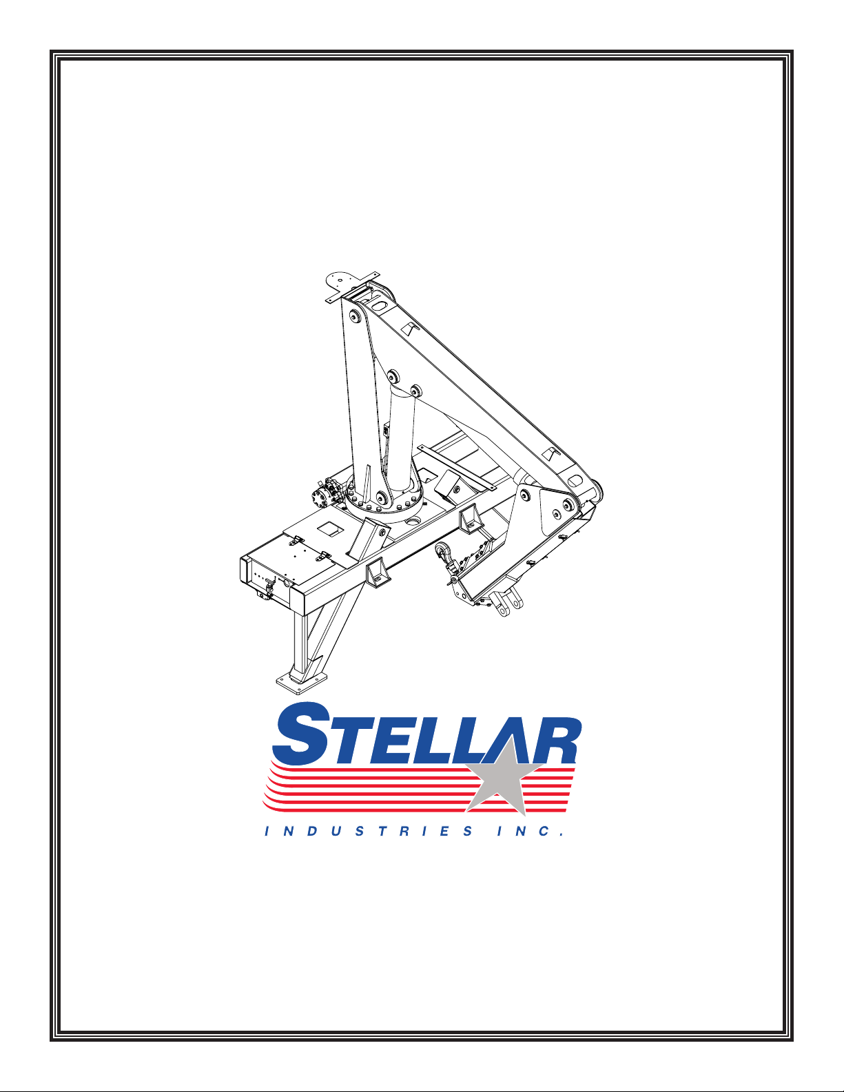
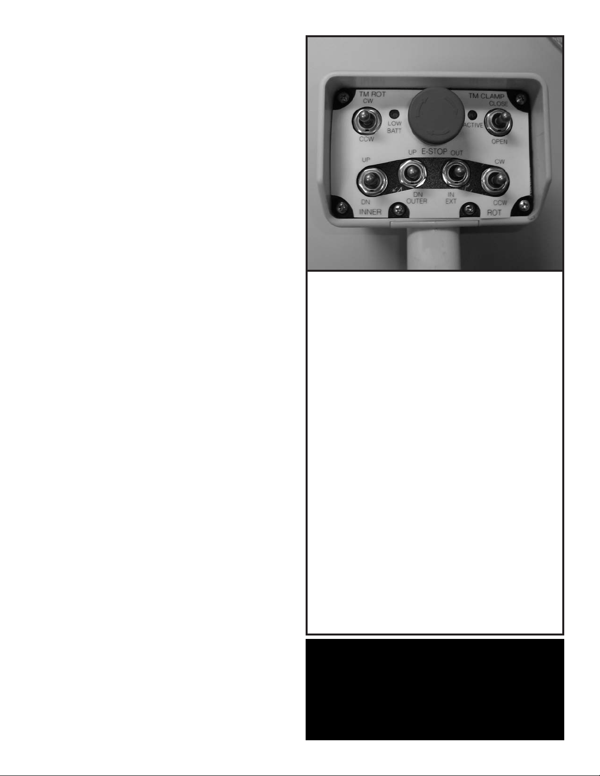
Radio Remote Operation
The crane is operated by a radio contr
which operates an electronic valve bank. The
controller (as shown above) operates the following
functions:
ol system
Manual Operation
In case of radio failure, the crane can be
operated using manual overrides located
on the valve bank.
Main Boom Up and Down
Outer Boom Up and Down
Extension Boom In and Out
Rotation Clockwise and Counter-Clockwise
TireMan Clockwise and Counter-Clockwise
TireMan Open and Close
To operate the crane, activate the desired toggle
switch. The crane will not function until the trigger
on the remote handle is activated. The crane
speed will change as the trigger is pulled or
eleased.
r
Note: If the crane does not operate, check the
batteries located in the r
eplace if necessary.
r
Note About Battery Condition
The batteries included with this equipment may be
emote handle and
rechargeable. To keep rechargeable batteries in
optimal working condition, follow these simple
guidelines:
1. Keep battery away from moisture. Store in a
2. Do not store or carry battery so that metal
cool, dry location.
objects can contact exposed metal end. Keep
battery cap on when not in use.
3.
4.
The batteries should be recharged when they
fail to pr
Never attempt to open the battery for any
oduce suf
ficient power
.
reason.
Valve Manual Override Operation
1. Activate Flow Control:
Turn override screw on flow control out.
2. Operate Solenoids:
Unlatch then push or pull to operate.
3. Deactivate Flow Control:
n override screw on flow control in.
ur
T
4. Have Unit Serviced.
Page 9
Operation 5
Crane Precautions
1. Movement of the control levers should be
slow and smooth to meter oil flow for safe
operation. Avoid jerky and sudden
movements.
2. The crane controls should be clearly marked
with decals. If these are missing or
illegible,replace immediately. (See Chapter
5: Decals)
3. Lift load slightly off the ground to check the
safety of the cargo. Do not use stability to
determine the safety. Consult the capacity
charts and strictly adhere to them.
4. Be constantly aware of the boom position
when operating the controls.
5. The boom tip should be centered directly
over the load before making the lift to avoid
swinging.
6. Do not drag loads with the crane.
7. Do not attempt to lift fixed loads.
8. Do not load boom in a sideways dir
9. Know the weight of the rigging and load to
avoid overloading the crane.
10. Do not extend or rotate a load over
anyone.
11. Wear protective gear such as hard hat,
safety glasses, steel-toed boots, and gloves.
ection.
Crane Transport
Before transporting the crane, do the following:
1. The crane must be in the stored position.
2. Outriggers must be securely stowed and not
extended horizontally or vertically.
3. Hook and sheave assemblies must be
securely fastened to prevent swinging.
4. All loose accessories, tools, and remote
controls must be securely stored in their
respective compartments or fasteners.
5. The PTO must be disengaged.
6. The parking brake must not be released
until all of the above procedures are
completed.
7. Do not drive the carrier vehicle while a load
is present on the hook.
8. Do not drive the carrier vehicle with less
than proper tire inflation.
9. Do not drive the carrier vehicle in areas
e the vertical clearance is unknown.
wher
10. Do not allow personnel to ride on the
equipment during transport.
Hook Precautions
1. Hooks are designed and manufactured to lift
specific loads. The specified rated load of a
hook applies to loads held uniformly in direct
tension and does not take into account
shock loads, hook tip loading, side loading,
bending, torsional, or related loads.
2. Do not attempt to lift a load that is larger
than the load rating of the hook.
Never use a hook’s yield point as an
3.
indicator of its capacity.
4. Do not use a hook to lift personnel.
5. Know the rated load of the hook in use.
6. Never weld attachments to a finished hook
in field applications. This will alter and
oy the design pr
destr
material.
7. Keep fingers, hands, body, and loose
clothing from between the hook and the
load.
void shock loading.
8. A
Inspect the hook r
9.
and maintain it in safe operating condition.
operties of the hook
egularly for excessive wear
The crane MUST be in the stored position before transporting.
Page 10

6 9000 Owner’s Manual
Operator Information
OPERATOR REQUIREMENTS
1. Operation is limited to the following
people:
A. Designated individual.
B. Trainees under direct supervision
of the designated individual.
C. Test or maintenance individual.
D. Crane Inspector.
2. Operators must meet the following
physical qualifications:
A. Vision of at least 20/30 Snellen in
one eye and 20/50 in the other,
with or without corrective lenses.
B. Ability to distinguish colors if color
ferentiation is required.
dif
C. Adequate hearing, with or
without a hearing aid.
D. No physical or emotional defects
that may create a hazar
operator or others.
E. Normal depth perception and
coordination.
3. In addition to the physical qualifications,
Operators must:
A. Demonstrate the ability to
understand all decals, the
owner’s manual, and any other
information requir
operation of the crane.
B. Be able to demonstrate the ability
to safely control the crane.
C. Know all safety regulations.
D. Be responsible for maintenance
requirements.
E. Understand and be fully capable
of implementing all emergency
procedures.
F. Understand the operating
procedures as outlined by this
manual, ANSI B30.5, and
Federal/State Laws.
ed for safe
d to the
OPERATOR CONDUCT
1. Operators will not engage in any
operation that would cause them to divert
attention away from the operation of the
crane.
2. Operators are responsible for all
operations under their direct control.
3. Operators will not leave a suspended
load unattended.
4. Operators will be familiar with the
equipment and the maintenance required
for proper care.
HANDLING THE LOAD
1. Size of the load:
Do not load the crane beyond
A.
the rated capacity.
It is the responsibility of the
B.
operator to know the weight of
the handled load.
2. Attaching the load:
A. Attach the load to the hook by
means of slings or other approved
devices.
B. Do not wrap the hoist rope
around the load.
3. Moving the load:
A. Make certain that the crane is
level and properly blocked.
B. Ensure that the load is secure and
balanced within the sling before
moving it.
C. Be sur
before moving the load. Use
stabilizer pads to ensure the
proper distribution of weight.
D. Do not drag the load sideways.
E. Make sure the hook is brought
over the load to minimize
swinging.
F. No suspended load should pass
over a person.
G. Avoid sudden starts and stops
when moving a load.
e that the crane is stable
Page 11

Chapter 3 - Maintenance
Maintenance 7
WARNING - Read the Following before
performing any maintenance on the
crane.
1. Only authorized service personnel are
to perform maintenance on the crane.
2. Disengage the PTO before any service
or repair is performed.
3. Do not disconnect hydraulic hoses
while there is still pressure in those
components.
4. Before disconnecting hydraulic
components, place the boom on the
ground or have it supported, shut off the
engine, release any air pressure on the
hydraulic reservoir, and move pedals
and control levers r
their operating positions to relieve all
pressures.
5. Keep the crane and service body
clean and fr
and dirt to prevent slippery conditions.
6. Perform all safety and maintenance
checks before each period of use.
7. Replace parts with Stellar Industries, Inc.
approved parts only.
8. Immediately repair or have repaired
any components found to be
inadequate.
Maintenance Procedures
1. Position the crane where it will be out of
the way of other operations or vehicles in
the area.
2. Be sure boom is lowered to the ground or
otherwise secured from dropping.
3. Place all controls in the off position and
secure operating features from
inadvertent motion.
4. Disconnect power source.
5. Relieve hydraulic oil pressure from all
hydraulic circuits before loosening or
removing hydraulic components.
6. Label or tag parts when disassembling.
ee from grease build-up, oil
epeatedly through
Daily Inspection
Daily Inspection should occur each day
before the crane is put into use. Each day,
inspect the crane for all of the following:
1. Hydraulic oil level.
2. Loose parts or damage to structures or
weld.
3. Cylinder movement due to leakage.
4. Hoses and gearboxes for evidence of oil
leaks.
5. Controls, including hand throttle for
malfunction or adjustment.
6. Truck hand brake operation.
7. All securing hardware such as cotter pins,
snap rings, hairpins, and pin keepers for
proper installation.
8. All safety covers for proper installation.
9. Cylinder holding valves for proper
operation.
10. Wire rope for broken wires, extensive
wear, distortion, and heat damage.
Periodic Inspection
Periodic Inspection should occur while the
crane is in use. For the duration of the
usage, inspect the crane for all of the
following:
1. Loose bolts and fasteners.
2. All pins, bearings, shafts, and gears for
wear, cracks, or distortion to include all
pivots, outriggers, sheave pins, and
bearings.
3. Hydraulic systems for proper operating
essure.
pr
4. Main frame mount bolts.
5. Cylinders for:
A. Damaged rods.
B. Dented barrels.
C. Drift from oil leaking internally.
D. Leaks at rod seals or holding valves.
6. PTO drive line system for proper
alignment, lubrication, and tightness.
7. Hydraulic hose and tubing for evidence of
damage such as blistering, crushing, or
abrasion.
Page 12

8 9000 Owner’s Manual
Weekly Inspection
Weekly Inspection should occur at the
beginning of every work week. Each week,
inspect the crane for all of the following:
1. Lubrication of points required by
lubrication chart located in this chapter.
2. Proper operation of load hook safety
latch.
3. Presence of this owner’s manual.
Monthly Inspection
Monthly Inspection should occur at the
beginning of every work month. Each
month, inspect the crane for all of the
following:
1. Frame bolt tightness - turn barrel nuts and
mounting bolts during the first month of
operation on new machines and then
quarterly thereafter.
2. Cylinders and valves for leaks.
3. Lubrication.
4. Load hook for cracks or having more than
15 percent normal throat opening or 10
degrees twist.
5. Structural members for bends, cracks, or
broken members.
6. All welds for breaks and cracks.
7. All pins and keepers for proper installation.
8. All control, safety, and capacity placards
for readability and secure attachment.
9. Inspect all electrical wires and
connections for worn, cut, or deteriorated
insulation and bare wire. Replace or
repair wires as required.
10. Tightness of all boom wear, pad-retaining
bolts.
Cleanliness
An important item in preserving the
long life of the crane is keeping
dirt, grime, and corrosive material
out of the working parts.
Thoroughly wash the crane
periodically.
Service
The following general suggestions should
be helpful in analyzing and servicing your
crane. Using the following systematic
approach should be helpful in finding and
fixing problems:
1. Determine the problem.
2. List and record possible causes.
3. Devise checks.
4. Conduct checks in a logical order to
determine the cause.
5. Consider the remaining service life of
components against the cost of parts
and labor necessary to replace them.
6. Make the necessary repair.
7. Recheck to ensure that nothing has
been overlooked.
8. Functionally test the new part in its
system.
Inspection Checklist
For a more detailed outline of scheduled
inspection points, refer to the Stellar
Inspection Checklist at the end of this
chapter. This list is an excellent guide for the
inspection tasks that will help maintain the
quality of your Stellar product. Feel free to
photocopy the checklist as needed.
ATTENTION
Every six (6) months, remove
the hydraulic pump from the
PTO and lubricate the splines
using Chelsea Lubricant
#379831 or Stellar PN 20885.
Failure to lubricate shaft
splines will cause damage to
the PTO and Hydraulic pump.
Page 13

Lubrication Recommendations
Component Location Recommendation
Engine Crankcase Apply Manufacturer’s
Recommendations
9Maintenance 9
Hydraulic System
Below –5*F
-5*F to 90*F
Above 90*F
Open Gears Hand Precision XL3 Moly EP 2 (NLGI 2 grease
Bearings, grease
(including turntable bearing
inner race)
Worm Drive Gearbox Gearbox Precision Synthetic EP 00 (NLGI 00)
Planetary Gearbox
(including winch)
Reservoir
Petro-Canada Arctic MV 15 (ISO 22)
Petro-Canada HYDREX 32 (ISO 32)
Petro-Canada HYDREX 46 (ISO 46)
with moly)
Gun Precision XL EP 2 (NLGI 2)
Gearbox Traxon Synthetic 75W-90 (API GL-5)
Wear Pad Lubrication Spray Gearshield NC
Compressor Fluids
Reciprocating Single Stage
Reciprocating Double Stage
Screw
-15˚F to 86˚F
-23˚F to 100˚F
32˚F to 113˚F
Crankcase
Crankcase
Crankcase
Compro 100 (ISO 100)
Compro 100 (ISO 100)
Compr
Compr
Compro XL-S 68 (ISO68)
o XL-S 32 (ISO 32)
o XL-S 46 (ISO46)
Greasing the Crane
Lubricate all grease gun points with
Extreme Pressure Grease - Stellar P/N: 22059.
Page 14
10 9000 Owner’s Manual
Holding Valve Inspection Procedure
The cylinders are equipped with holding
valves that prevent sudden movement of
the cylinder rods in the event of a hydraulic
hose or hydraulic component failure. The
valve is checked in the following manner:
1. Identify the cylinder in question.
2. Identify the holding valves and the
cylinder direction in question.
a. Cylinder Extend.
b. Cylinder Retract.
3. Place the machine so that the cylinder
will be located in the appropriate testing
position.
4. Pick the load (Do not exceed capacity,
rated or stability).
5. Disengage hydraulics.
6. Operate crane functions.
A. If the cylinder creeps (lowering the
load), replace the holding valve.
B. If the cylinder does not creep (load
stays suspended), the valve is
operational.
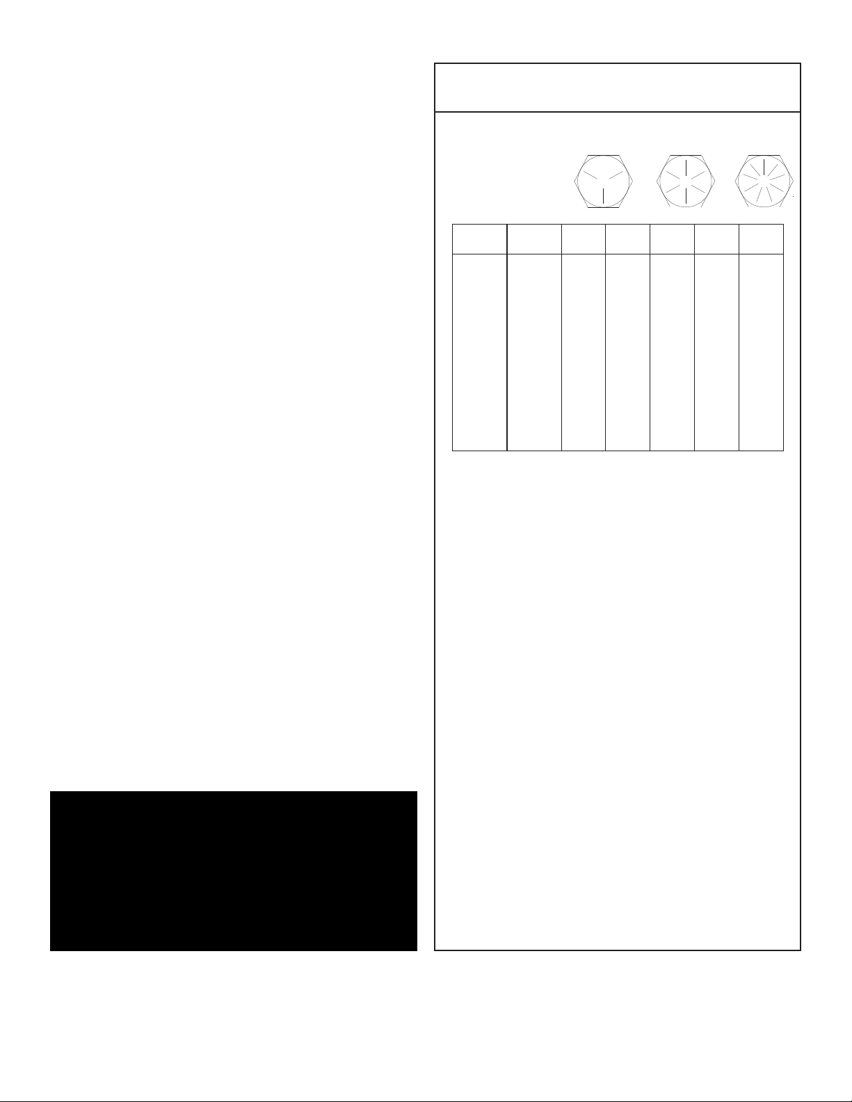
Torque Data Chart
Grade 5
Plated
Size
DIA-TPI)
(
/16-18
5
3/8-16
7/16-14
1/2-13
9/16-12
5/8-11
3/4-10
7/8-9
1-8
1 1/8-7
1 1/4-7
1 3/8-6
1 1/2-6
Bolt DIA
Inches)
(
.3125
0
0.3750
0.4375
0.5000
0.5625
0.6250
0.7500
0.8750
1.000
1.1250
1.2500
1.3750
1.500
Plain
Ft-Lb)
(
7
1
31
49
75
110
150
265
395
590
795
1120
1470
1950
Ft-Lb)
(
1
23
37
57
82
115
200
295
445
595
840
110
1460
When using the torque data in the charts
above, the following rules should be
observed.
Grade 8
Plated
Plain
Ft-Lb)
(
3
5
2
44
70
105
155
220
375
605
910
1290
1815
2380
3160
Ft-Lb)
(
8
1
33
52
80
115
160
280
455
680
965
1360
1780
2370
Grade 9
Plated
Ft-Lb)
(
2
39
63
96
139
192
340
549
823
1167
1646
2158
2865
2
Gear-Bearing Bolt Maintenance
Anytime a gear-bearing bolt is removed, it
must be replaced with a new bolt of the
identical grade and size. Once a bolt has
been torqued to 75% of its proof load and
then removed, the torque coefficient may
no longer be the same as when the bolt was
new thus giving indeterminate damp loads
after torquing.
Warning!
Failure to replace gear-bearing
bolts may result in bolt failure due
to metal fatigue causing serious
injury or even death.
1. Bolt manufacturer’s particular
specifications should be consulted when
provided.
2. Flat washers of equal strength must be
used.
3. All torque measurements are given in
foot-pounds. To convert to inch-pounds,
multiply by 12.
4. Torque values specified are for bolts with
residual oils or no special lubricants
applied. If special lubricants of high stress
ability, such as Never-Seez compound
graphite and oil, molybdenum disulphite,
colloidal copper or white lead are
applied, multiply the tor
que values in the
charts by the factor .90. The use of Loctite
does not affect the tor
que values listed
above.
5. Torque values for socket-head capscrews
are the same as for Grade 8 capscrews.
Page 15
Inspection Checklist
Maintenance 11
Use of this checklist is subject to terms of the
Stellar Warranty information. Additional copies of
this checklist can be obtained by contacting
Stellar Customer Service at (800) 321-3741.
Owner/Company:
Contact Person:
Crane Make/Model:
Crane Serial:
Type of Inspection (check one)
Daily (if deficiency found)
Monthly
Date Inspected:
Hour Meter Reading:
Inspected by: (
Signature of Inspector:
print)
Quarterly
Annual
Type of Inspection Information
Daily and monthly inspections are to be performed by a “designated” person, who has
been selected by the employer or the employer’s representative as being competent to
perform specific duties.
Quarterly and annual inspections are to be performed by a “qualified” person who, by
possession of a recognized degree in an applicable field or certificate of professional
standing, or who, by extensive knowledge, training and experience has successfully
demonstrated the ability to solve or resolve problems related to the subject matter and
work.
One hour of normal crane operation assumes 20 complete cycles per hour
exceeds 20 cycles per hour, inspection frequency should be increased accordingly.
Consult the Stellar Owner’s Manual for additional inspection items.
Before inspecting and operating the crane, make certain that t he crane is set up away
from power lines and leveled with outriggers fully extended.
Daily (D): Before each day of operation, those items with a (D) must be inspected. This
inspection need not be recorded unless a deficiency is found.
Monthly (M): Monthly inspections or 100 hours of normal operation (which ever comes
first) includes all daily and monthly inspection items plus items designated with a (Q). This
inspection must be recorded.
Quarterly (Q): Every three months or 300 hours of normal operation (which ever comes
first) includes all daily and monthly inspection items plus items designated with an (M).
This inspection must be recorded.
Annual (A): Each year or 1200 hours of normal operation (which ever comes first) includes
all items on this form which encompasses daily, monthly, and quarterly inspections plus
those items designated by (A). this inspection must be recorded.
. If operation
Page 16

12 9000 Owner’s Manual
Daily Inspection
Frequency
D
D
D
D
D
D
D
D
D
D
D
Key
Decals
Controls
Station
Hydsystem
Hook
Rope
Pins
General
Operation
Remote Ctrls
Electrical
Inspection Description
All load charts, safety & warning Decals, & control Decals are present and
egible.
l
Check all safety devices for proper operation.
Control mechanisms for proper operation of all functions, leaks, & cracks.
Control mechanisms for proper operation of all functions, leaks, & cracks.
Hydraulic system (hoses, tubes, & fittings) for leakage & proper oil level.
Presence & proper operation of hook safety latches.
Proper reeving of wire rope on sheaves & winch drum.
Proper engagement of all connecting pins & pin retaining devices.
Overall observation of crane for damage or missing parts, cracked welds &
presence of safety covers.
During operation, observe crane for abnormal performance, unusual wear.
If observed, discontinue use & determine cause & severity of hazard.
Operate remote control devices to check for proper operation.
Operate all lights, alarms, etc. to check for proper operation.
Status
D
D
D
Anti 2-Blocking
Operation Aid
Operation Aid
Operate anti 2-blocking device to check for proper operation.
Check presence of boom angle indicator.
Check overload device for proper operation.
Page 17

Monthly Inspection
Maintenance 13
Frequency
M
M
M
M
M
M
M
M
M
M
M
M
Key
Daily
Cylinders
Valves
Valves
Valves
General
Electrical
Structure
Welds
Pins
Hardware
Wear Pads
Inspection Description
All Daily Inspections.
Visual inspection of cylinders for leakage at rod, fittings, & welds. Damage
to rod & case.
Holding valves for proper operation.
Control valve for leaks at fittings & between sections.
Control valve linkages for wear, smoothness of operation & tightness of
fasteners. Relief valve for proper pressure settings.
Bent, broken or significantly rusted/corroded parts.
Electrical systems for presence of dirt, moisture & frayed wires.
All structural members for damage.
All welds for breaks & cracks.
All pins for proper installation & condition.
All bolts, fasteners & retaining rings for tightness, wear & corrosion.
Condition of wear pads.
Status
M
M
M
M
M
M
M
M
M
M
Pump & Motor
PTO
Hyd Fluid
Hyd Lines
Hook
Rope
Manual
Chassis
Chassis
Station
Hydraulic pumps & motors for leakage at fittings, seals & between sections.
Check tightness of mounting bolts.
Transmission/PTO for leakage, abnormal vibration & noise, alignment &
mounting bolt torque.
Quality of hydraulic fluid and for presence of water.
Hoses & tubes for leakage, abrasion damage, blistering, cracking,
deterioration, fitting leakage, & secured properly.
Load hook for abnormal throat distance, twist, wear, & cracks.
Condition of load line.
Presence of operator's manuals with the unit.
Tire wear and air pressure.
Working backup alarm.
Fire extinguisher at cab or machinery housing.
Page 18

14 9000 Owner’s Manual
Quarterly Inspection
Frequency
Q
Q
Q
Q
Q
Key
Daily
Monthly
Rotation Sys
Hardware
Structure
Inspection Description
All daily inspections.
All monthly inspections.
Rotation bearing for proper torque of all mounting bolts.
Base mounting bolts for proper torque.
All structural members for deformation, cracks, & corrosion.
Base
Outrigger beams & legs
Mast
Inner boom
Outer boom
Extension(s)
Jib boom
Status
Q
Hardware
Jib extension(s)
Other
Other
Pins, bearings, shafts, gears, rollers, & locking devices for wear, cracks,
corrosion, & distortion.
Inner boom pivot pin(s) & retainer(s)
Outer boom pivot pin(s) & retainer(s)
Inner boom cylinder pin(s) & retainer(s)
Outer boom cylinder pin(s) & retainer(s)
Extension cylinder pin(s) & retainer(s)
Jib boom pin(s) & retainer(s)
Jib cylinder pin(s) & retainer(s)
Jib extension cylinder pin(s) & retainer(s)
Boom tip attachments
Other
Other
Page 19

Quarterly Inspection Continued...
Maintenance 15
Frequency
Q
Q
Q
Key
Hyd Lines
Pumps&Motors
Valves
Inspection Description
Hoses, fittings, & tubing for proper routing, leakage, blistering, deformation,
excessive abrasion.
&
Pressure line(s) from pump to control valve
Return line(s) from control valve to reservoir
Suction line(s) from reservoir to pump
Pressure line(s) from control valve to each function
Load holding valve pipe(s) and hose(s)
Other
Pumps and motors for loose bolts/fasteners, leaks, noise, vibration, loss of
performance, heating and excess pressure.
Winch motor(s)
Rotation motor(s)
Other
Hydraulic valves for cracks, spool return to neutral, sticking spools, relief
valve failure.
Main control valve
Status
Q
Q
Q
Cylinders
Winch
Hyd Filter
Load holding valve(s)
Outrigger or auxiliary control valve(s)
Other
Hydraulic cylinders for drifting & leakage. Rods for nicks, scores, & dents.
Castor damage. Case & rod ends for damage & abnormal wear.
Outrigger cylinder(s)
Inner boom cylinder(s)
Outer boom cylinder(s)
Extension cylinder(s)
Rotation cylinder(s)
Jib lift cylinder(s)
Jib extension cylinder(s)
Other
Winch, sheaves, & drums for damage, abnormal wear, abrasion, & other
egularities.
irr
Hydraulic filters for r
eplacement per maintenance schedule.
Page 20

16 9000 Owner’s Manual
Annual Inspection
Frequency
A
A
A
A
A
A
A
A
A
A
A
A
Key
Daily
Monthly
Quarterly
Hyd System
Controls
Valves
Valves
Rotation Sys
Lubrication
Hardware
Wear Pads
Loadline
Inspection Description
All daily inspection items.
All monthly inspection items.
All quarterly inspection items.
Hydraulic fluid change per maintenance schedule.
Control valve calibration for correct pressures & relief valve settings.
Safety valve calibration for correct pressures & relief valve settings
Valves for failure to maintain correct settings.
Rotation drive system for proper backlash clearance & abnormal wear,
deformation, & cracks.
Gear oil change in rotation drive system per maintenance schedule.
Check tightness of all fasteners and bolts.
Wear pads for excessive wear.
Loadline for proper attachment to drum.
Status
A
A
A
Historic Data
Historic Data
Historic Data
Monthly inspection records.
Maintenance records.
Repair and modification records.
Page 21

Inspection Notes
Maintenance 17
Page 22

18 9000 Owner’s Manual
Page 23

Chapter 4 - Specifications
Model 9000 Crane
SPECIFICATION SHEET
Crane Rating: 90,000 ft-lbs (12.44 ton meters)
Standard Boom Length: 12’ 11” (3.94 m) from CL of Crane
Boom Extension: Hydraulic 37" (94 cm)
Maximum Horizontal Reach: 16’ (4.87 m) from CL of Crane
Maximum Vertical Lift: 22’ (6.71 m)
(From Truck Frame)
Cylinder Specifications
Inner Lift Cylinder: 6” (15.24 cm) bore with integral
pilot operated counterbalance valves.
Outer Lift Cylinder: 5” (12.70 cm) bore with integral
pilot operated counterbalance valves.
1
Extension Cylinder: 3
⁄2” (8.89 cm) bore with integral
pilot operated counterbalance valves.
19Specifications 19
Rotation: 290 degree power
(Worm Gear Drive)
Lifting Capacities: 9,000 lbs @ 10’ (4080 kg @ 3.03 m)
6,950 lbs @ 12’11” (3150 kg @ 3.94 m)
5,625 lbs @ 16’ (2550 kg @ 4.87 m)
Power Supply Requir
Controls: Proportional Radio Controls standard
for all functions.
Stowed Height: 75” (190.5 cm)
(Above Truck Frame)
Mounting Space Required: 32” (81.3 cm)
oximate Shipping Weight: 4,200 lbs (1590 kg)
Appr
ed: PTO & Pump
(8.0 gpm @ 3000 psi)
(30.3 lpm @ 206 bars)
Page 24

20 9000 Owner’s Manual
10’
3.05m
16’
4.87m
12’11”
3.94m
10’
3.05m
16’
4.87m
12’11”
3.94m
10’
3.05m
25’4”
7.72m
22’6”
6.86m
CAPACITY
CHART
9000 lbs
4080 kg
6950 lbs
3150 kg
5625 lbs
2550 kg
0’
0m
TRUCK
GROUND
0’
0m
190 STATE STREET GARNER, IA 50438
PHONE: (800) 321-3741 FAX: (641) 923-2812
9000
Capacity Chart - Decal PN 29559
Page 25

Chapter 5 - Decals
Decals of Note
21Decals 21
Crane Base Decals
Crane Outrigger Decals
Page 26

22 9000 Owner’s Manual
Crane Cover Decals
Electrocution Hazard Decal
Location: Crane Base
Function: T
the hazard associated with contact or proximity to electrical lines, the
possible consequences should the hazard occur and how to avoid the
hazard. PN: 4187
o inform the operator and other personnel in the work area of
Crane Base Decals
Operation Hazard Decal
Location: Crane Base
Function: T
personnel in the work area of the hazard
associated with improper maintenance and
unauthorized modifications, the possible
consequences should the hazard occur, and
how to avoid the hazard.
PN: 4190
o inform the operator and other
Operation Hazard Decal
Location: Crane Base
Function: To inform the operator of the
need for proper training, familiarity with
safe operating pr
possible consequences without training.
PN: C4540
ocedur
es and , the
Page 27

Crane Base Decals
23Decals 23
Operation Hazard Decal
Location: Crane Base
Function: To inform the operator of the need for
proper training, familiarity with safe operating
procedures, and the possible consequences of
operation without training.
PN: C4544
Operation Hazard Decal
Location: Crane Base
Function: To inform the operator of the hazard
associated with overloading the crane, the
possible consequences should the hazard
occur, and how to avoid the hazard.
PN: 4189
Electrocution Hazard Decal
Location: Crane
Function: T
the hazard associated with contact or proximity to electrical lines, the
possible consequences should the hazar
hazar
PN: C1179
o infor
d.
m the operator and other personnel in the work ar
d occur and how to avoid the
ea of
Page 28

24 9000 Owner’s Manual
Outrigger Decals
Foot Crushing Hazard Decal
Location: Outrigger Leg
Function: To inform the operator and other
personnel in the work area of the hazard
associated with the operation of the outriggers,
the possible consequences should the hazard
occur, and how to avoid the hazard.
PN: C4795
Moving Boom Hazard Decal
Location: Crane Base
Function: To inform the operator and other
personnel in the work area of the hazard
associated with a moving boom, especially while
stowing and unfolding the crane, the possible
consequences should the hazard occur, and how
to avoid the hazard.
Moving Outrigger Hazard Decal
Location: Outrigger Leg
Function: T
associated with outrigger operation, the possible
consequences should the hazard occur, and how
to avoid the hazard
PN: C5918
o inform the operator of the hazard
.
Crane Outrigger Decals
Page 29

25Decals 25
(USE WITH BODY PACKAGE)
DECAL-AL IGNMENT
DECAL-ELECTROCUTION 3.25x7.5
PART No.
02
ITEM
01 4188
4187
DESCRIPTION
1
1
QTY
THESE DECALS NOT SHOWN
15
DECAL-ELECTROCUTION 4.5x7.5
DECAL-S TELLAR APPROVED ATTACHMT
DECAL-DANGER MOVING O.R.
DECAL-DANGER
DECAL-DANGER
DECAL-DANGER
DECAL-ELECTROCUTION 2x2.75
DECAL-DANGER STOWING
DECAL-DANGER O.R.
DECAL-ELECTROCUTION 5x13
DECAL-DANGER
C4545
C4540
C454405
03
04
C454108
06
07 4189
4186
C4795
C591811
09104190
C1179
16973
14
12
13
DECAL ASME/ANSI B30.22/B30.5
DECAL WORM GEAR LUBRICATION
15172
9188
1
4
1
2
1
1
2
1
2
1
1
2
2
DECAL-OR PANEL
DECAL-I DENTIFICATION
DECAL-S ERVICE
DECAL-CAPACITY
DECAL-D IESEL FUEL ONLY
DECAL-S TELLAR 2x4.5
DECAL-F LOOD LIGHT
DECAL-S TELLAR 4x9.5
21 29559
18 C0568
C5911
C5910
17
16
20
19 4305
4214
24
22
23
DECAL CRANE OUTRIGGER
DECAL GREASE WORM DRIVE BEARINGS
4158
15171
13036
25 30487
2
2
3
1
1
1
1
1
1
2
TOP OF COVER
26
26 28841 DECAL OMNEX RADIO OPERATION 1
35234*27 DECAL STELLAR MADE IN THE USA 1
*THESE DECAL NOT INCLUDED WITH THE DECAL KIT
12
21
7
4
9
5
2
24
22
23
20
15
14
8
11
10
25
13
E-stop
Opt
Ext
Boom
Winch
S
tart/
Rot
S
top
E
ng
27
Compressor
Speed Control
i
n
out
d
n
updnup
ccw
c
w
S
top
Start
PN 30488
Decal Kit Placement Kit 30488
Page 30

26 9000 Owner’s Manual
Page 31

Chapter 6 - Installation
Notice: Read this Page Before Installation of the Crane
27Installation 27
General Installation
This chapter is designed to serve as a general guide
for the installation of a Stellar 9000 Articulating Crane
on a Stellar Service Body. Each installation is
considered unique so certain portions of this chapter
may or may not apply to your direct application. If a
question should arise during the installation process,
please contact Stellar Customer Service at (800) 321
3741.
This crane is designed for use with a Stellar Service
Body installed on a vehicle that meets the minimum
chassis requirements of the crane. Check with Stellar
Industries before installing this crane on a body other
than a Stellar Service Body.
WARNING!
The use of this crane on a body not
capable of handling the loads imposed on
it may result in serious injury or death.
Notice:
PTO and Pump installation instructions are provided
by the corresponding manufacturers. For more
information on which PTO and Pump fit your
application, please contact your local Stellar
Distributor or Stellar Customer Service.
Installation Notice
According to Federal Law (49 cfr part 571), each
final-stage manufacturer shall complete the vehicle
in such a manner that it conforms to the standards in
effect on the date of manufacture of the incomplete
vehicle, the date of final completion, or a date
between those two dates. This requirement shall,
however, be superseded by any conflicting provisions
of a standard that applies by its terms to vehicles
manufactured in two or more stages.
Therefore, the installer of Stellar cranes and bodies is
considered one of the manufacturers of the vehicle.
As such a manufacturer, the installer is responsible for
compliance with all applicable federal and state
regulations. They are required to certify that the
vehicle is in compliance with the Federal Motor
Vehicle Safety Standards and other regulations issued
under the National Traffic and Motor Vehicle Safety
Act.
Please reference the Code of Federal Regulations,
title 49 - Transportation, Volume 5 (400-999), for further
information, or visit
http://www.gpoaccess.gov/nara/index.html for the
full text of Code of Federal Regulations.
Installation Overview
Installation Guidelines (For more detail,
please contact Stellar Customer Service)
Locate mounting brackets and clamp to
1.
chassis 1” (min) from rear of cab (or desired
location).
2. Set crane on chassis and check for
interferences.
3. Using mounting bracket as a guide, mark holes
to be drilled into truck frame.
4. Remove mounting brackets and drill holes.
5. Mount brackets using 3/4” Grade 8 bolts, flast
washers, and nyloc nuts.
6. Lower crane onto mounting brackets.
7. Mount crane using 1” Grade 8 bolt, flat
washers, and nyloc nuts.
8. Connect pressure and return lines per
hydraulic kit.
9. Connect (+12V) Power and ground wires inside
crane box.
10. Check reservoir for oil and fill if necessary
1. Operate crane several cycles.
1
.
Install Kit (PN 32307)
Page 32

28 9000 Owner’s Manual
Page 33

35
NOTE: ATTACH (2) 14" LONG
PIECES OF WEATHERSTRIP,
P/N 17162, TO COVER P/N 30005
21
4
1
11
39
3
4
14
37
15
1
7
8
2
40
9
6
5
12
13
16
17
23
2
2
24
20
25
18
24
25
42
26
25
19
22
27
28
27
29
30
33
32
34
36
10
31
.YTQNOITPIRCSEDTRAPMETI
10009 ESA
B
448821
2C6219 WASHER 0.75 SAE FLAT YELLOW GR8 20
3D1312 CAP SCR 0.63-11X3.50 HHGR8 2
2
COL
YN HH 11-36
.0 TUN62
82
4
205
.52X00
.2 REDNILY
C
37
70D5
2
0006 SS GEL REGGIRTUO71846
205.6X00.1 NIP69737
40
01-0027 DI 00.1 GNIR PANS01108
252.3X00
.1 NIP21
94
9
4
L
ANRE
TNI 00.1 GNIR PA
NS57830
1
11 D1295 CAP SCR 0.50-13X1.50 SH GR5 4
12 10974 VB 2 SECT W/PB VDM6-4-4-YE-HP 1
13 C0927 CAP SCR 0.31-18X2.25 HHGR5 2
4
C
NIZ TALF SSU 13
.0 REHSA
W343
0
41
15 26766 GUARD TTB 6000 GP BEARING 1
16 0484 CAP SCR 0.31-18 X 0.50 HHGR5 4
10009 ESAB REVOC5000371
2HSULF SS EGN
IH10
06C
81
1
C
NIZ )T( REBB
UR HCTAL6184C
91
1LABICE
D 79. MRALA
PUKCA
B5400D
0
2
21 D0896 CAP SCR #10-24X0.75 FHSH SS 3
5SS COLYN HH 42-01# TUN
65
94C22
.Y
TQNOITPIRCS
ED
TRA
PMETI
23 D1711 CAP SCR #10-24X0.50 BTNHD SS 2
24 C6021 CAP SCR 0.25-20X0.75 BTNHD SS 10
21COLYN 5RGHH 02-52.0 T
UN
3330
5
2
26 D0528 CAP SCR 0.25-20X1.25 BTNHD SS 2
27 D1345 FTG CPRSN 0.12NPT/0.25 TUBE 2
28 D1810 TBE AIR SAEJ844 TYPE A .25 (28") 1
131.0 EPIP RELPUOC GTF6522C92
1
THGIARTS TPN 8/1 KRE
Z
2951c
0
3
1REBBUR 00.1 PMALC326713
32 30489 CAP CORDED BACKUP OMNEX 1
33 18611 SCREW #6-32X0.38 HH MACH SELF TAP 1
2TNALS REGGIRTUO MSA PAC0940343
35 30494 VB 6 SECT ELECT W/PROP STERLING 8 GPM 1
36 C0954 CAP SCR 0.38-16X4.50 HHGR5 2
2TALF 83.0 REHSAW643073
2COLYN HH 61-83.0 TUN7430
8
3
10009 EVIRD GNIWS GNIRAEB1923393
40 5841 CAP SCR 0.75-10X4.50 HHGR8 ZY 20
41 33941 MOTOR 9000, WHITE 500260C3120DEAAA 1
PN 29349
Chapter 7 - Assembly Drawings
Base Assembly - PN 29349
Note: Outrigger Cylinder
uses Stellar Seal Kit P/N 1099
29Assembly Drawings 29
Page 34

30 9000 Owner’s Manual
10
8
2
6
7
12
4
3
5
12
7
2
8
12
8
7
2
2
6
7
8
12
9
11
?
.Y
T
QNOITPIRCSEDTRA
P
ME
TI
1
0009 TSAM1
8
9721
20635 BUSHING 40DXR32 GARLOCK 4
3 C6219 WASHER 0.75 SAE FLAT YELLOW GR8 18
44974 CAP SCR 0.75-10X2.50 HHGR8 ZY 18
529352 CYLINDER ASM 6.00X28.63 1
2
T
&D 52.31
X
0
5.2 NI
P
0
37
96
78377 PIN CAP 0.56X3.50X.25 4
8D0790 WASHER 0.50 FLAT GR8 4
10
0
09
P
M
ALC E
SOH
9
00
0
39
2
K
COL 83
.0
RE
HS
AW32500
1
11 C0944 CAP SCR 0.38-16X1.75 HHGR5 2
12 10172 CAP SCR 0.50-13X1.00 HHGR8 ZY 4
PN 29350
Mast Assembly - PN 29350
Note: Main Lift Cylinder uses
Stellar Seal Kit P/N 38971
Page 35

12
10
9
1
8
3
6
7
11
5
2
4
10
11
3
12
.YTQNOITPIRCSEDTRAPMETI
10009 MOOB RENNI663821
229356 CYLINDER ASM 5.00X30.00 1
30635 BUSHING 40DXR32 GARLOCK 4
44381 BUSHING 32DXR32 2.00X2.00 GARLOCK 2
54380 BUSHING 32DXR24 2.00X1.50 GARLOCK 2
1T&D 31.01X05.2 ,NIP853926
1T&D 91.01X00.2 NIP90797
252.X05.3X65.0 P
AC
NI
P
773
8
8
252.X00.3X65.0 PAC NIP54159
48
RG TALF
05.0
REHSA
W0970
D0
1
11 10172 CAP SCR 0.50-13X1.00 HHGR8 ZY 4
2THGIARTS TPN 8/1 KREZ2951c21
PN 29354
Main Boom Assembly - PN 29354
31Assembly Drawings 31
Note: Secondary Cylinder
uses Stellar Seal Kit P/N 38680
Page 36

32 9000 Owner’s Manual
3
7
7
6
1
8
1
7
16
5
1
9
8
20
11
4
12
19
2
1
0
13
14
12
6
20
6
20
12
6
7
6
3
15
21
22
.YTQ
N
OITPIRCSEDTR
AP
METI
10009 MOOB RETUO5738
21
10009 MOOB TXE1329
22
39435 WEAR PAD 1.44X3.00 RND NYLATRON 6
100.73X05.3 REDNILYC063924
6
0
0
09 DAP RAEW REVOC155925
6D0790 WASHER 0.50 FLAT GR8 32
710666 CAP SCR 0.50-13X1.25 HHGR8 24
84380 BUSHING 32DXR24 2.00X1.50 GARLOCK 4
1T&D 31.21X00.2 NIP2400
29
2T&D 83.01X00.
2 NIP3400
201
1T&D 36.5X00.2 NIP2559211
8
5
2.X00.3X65.0 PAC N
IP541
521
13 26762 HOOK 7 TON SWIVEL CROSBY 1028632 1
1
31
.5X5
2.1 HCTIH N
IP2
91541
15 28496 COLLAR 1.28x1.75x1.00 2
16 8622 CLAMP HOSE/TUBE AG-2 4
17 0343 WASHER 0.31 USS FLAT ZINC 4
4COLYN HH
81-1
3.0 TUN24308
1
19 30483 WEAR PAD 0.34X3.00 RND 2
20 10172 CAP SCR 0.50-13X1.00 HHGR8 ZY 8
21 0249 BUSHING BPC-2022-20 1.25X1.25 3
22 c1592 ZERK 1/8 NPT STRAIGHT 1
PN 29359
Extension Boom Assembly - PN 29359
Note: Extension Cylinder uses
Stellar Seal Kit P/N 38679
Page 37

Chapter 8 - Hydraulics - Electrical
Do not rely on the hydraulic fluid to support
WARNING!
Please read the following section before
performing any work on the
hydraulic/electrical system of your crane.
This section contains vital safety information
and maintenance guidlines for your crane.
If questions should arise, please contact
Stellar Customer Service at 800-321-3741
Never modify or alter any of the equipment,
whether mechanical, electrical, or hydraulic,
without Stellar Industries’ approval.
Release system pressure before attempting to
make adjustments or repairs.
Do not attempt service or repair when PTO is
engaged.
Disassemble and assemble hydraulic
components on a clean surface.
the boom or crane.
Contaminants in a hydraulic system affect
operation and will result in serious damage to
the system components. Dirty hydraulic
systems are a major cause of component
failures.
If evidence of foreign particles is found in the
hydraulic system, flush the system.
When installing metal hydraulic tubes, tighten
all bolts finger tight. Then , in order, tighten the
bolts at the rigid end, the adjustable end, and
the mounting brackets. After tubes are
mounted, install the hoses. Connect both
ends of the hose with all bolts finger tight.
Position the hose so it does not rub the
machine or another hose and has a minimum
of bending and twisting. Tighten bolts in both
couplings.
33Hydraulics - Electrical 33
Clean all metal parts in a nonflammable
cleaning fluid. Then lubricate all components
to aid in assembly.
Hydraulic fluid expands when heated. This
raises the pressure in an unventilated tank.
Release the tank pressure before removing the
cap completely. Failure to do so may cause
the oil to shoot out of the tank very rapidly and
cause severe burns.
Warning! If hydraulic fluid escapes, the boom
or crane can fall immediately. Make sur
ound or blocking is supporting the boom
gr
before performing any maintenance or repair.
e the
Due to manufacturing methods, there is a
natural curvature to a hydraulic hose. The
hose should be installed so any bend is with
this curvature.
Page 38

34 9000 Owner’s Manual
PN 29556
Control Kit - PN 29556
Page 39

PN 29557
Hydraulic Kit - PN 29557
35Hydraulics - Electrical 35
Page 40

36 9000 Owner’s Manual
Page 41

Chapter 9 - Replacement Parts
37Replacement Parts 37
HYDRAULIC SYSTEM COMPONENTS
ART#DESCRIPTION
P
397OIL PRESSURE GAUGE
6
4960FLOW VALVE (PROPORTIONAL)
2
5369SEAL KIT (FLOW VALVE)
2
5367RELIEF VALVE
2
25368 SEAL KIT (RELIEF VALVE)
31077 SOLENOID VALVE (TANDEM)
31526 SEAL KIT (TANDEM SOLENOID VALVE)
25370 COIL (FLOW VALVE AND SOLENOID VALVES)
4587 PRESSURE SWITCH (OVERLOAD)
3941HYDRAULIC SWING MOTOR
3
2027O RING (#4 FACE SEAL) (HYDRAULIC FITTINGS)
C
2028O RING (#6 FACE SEAL) (HYDRAULIC FITTINGS)
C
2029O RING (#8 FA
C
2223O RING (#10 FACE SEAL) (HYDRAULIC FITTINGS)
3
1245O RING (#4 SAE PORT SIDE) (HYDRAULIC FITTINGS)
D
D1246 O RING (#6 SAE PORT
1247O RING (#8 SAE PORT SIDE) (HYDRAULIC FITTINGS)
D
1248O RING (#10 SAE PORT SIDE) (HYDRAULIC FITTINGS)
D
1099 SEAL KIT (OUTRIGGER CYLINDER)
38971 SEAL KIT (MAIN LIFT CYLINDER)
38680 SEAL KIT (SECONDARY CYLINDER)
38679 SEAL KIT (EXTENSION CYLINDER)
16154 MANIFOLD ASSEMBLY (MAIN AND SECONDARY CYLINDERS)
9803 COUNTERBALANCE VALVE (CYLINDERS)
29353 TUBE ASSEMBLY (MAIN LIFT CYLINDER)
29357 TUBE ASSEMBLY (SECONDARY CYLINDER)
13554 QUICK COUPLER-HYDRAULIC 0.38 FEMALE
13555 QUICK COUPLER-HYDRUALIC 0.38 MALE
13556 QUICK COUPLER-HYDRAULIC 0.50 FEMALE
13557 QUICK COUPLER-HYDRAULIC 0.50 MALE
CE SEAL) (HYDRAULIC FITTINGS)
SIDE) (HYDRAULIC FITTINGS)
ASSEMBLY COMPONENT PARTS
PART# DESCRIPTION
#0635 BUSHING 2.50" X 2.00"
4381 BUSHING 2.00" X 2.00"
4380 BUSHING 2.00" X 1.50"
#0249 BUSHING 1.25" X 1.25"
8377 PIN CAP 0.56" X 3.50" x 0.25"
5145 PIN CAP 0.56" X 3.00" x 0.25"
10172 CAP SCREW 0.50-13 X 1.00" GRADE 8
D0790 WASHER .50 SAE FLAT GRADE 8
C1592 GREASE ZERK 1/8 NPT STRAIGHT
9435 WEAR P
30483 WEAR PAD 0.34" X 3.00" ROUND
26762 HOOK 7-TON
5192 HITCH PIN 1.25" X 5.13"
28496 COLLAR - HOOK
38676 SAFETY LA
C6001 HINGE (VALVE BANK COVER)
C4816 LATCH RUBBER (VALVE BANK COVER)
#0110 SNAP RING 1.00" ID
#0108 SNAP RING 2.00" ID
30009 HOSE CLAMP (CRANE MAST)
8622 HOSE CLAMP (SECONDAR
AD 1.34" X 3.00" ROUND
TCH
Y)
LECTRICAL COMPONENTS
E
ART#DESCRIPTION
P
1661TOGGLE SWITCH (OMNEX RADIO REMOTE)
3
35433 E-STOP SWITCH (OMNEX RADIO REMOTE)
1662HANDLE / TRIGGER ASM (OMNEX RADIO REMOTE)
3
28832 CABLE BACK UP (OMNEX RADIO REMOTE)
1663BATTERY COVER (OMNEX RADIO REMOTE)
3
D0045 ALARM (OVERLOAD)
8837TRANSMITTER (OMNEX RADIO SYSTEM)
2
28836 RECEIVER (OMNEX RADIO SYSTEM)
COMPRESSOR COMPONENTS (SHD66 OPTIONAL)
ART#DESCRIPTION
P
3853 PILOT VALVE 145/175 PSI
4913SOLENOID VALVE (SHD66 COMPRESSOR)
C
C4914 PRESSURE RELIEF V
C0864 AIR PRESSURE SWITCH -HOBBS (SHD66 COMPRESSOR)
471LOW PRESSURE INTA
7
7472 HIGH PRESSURE INTAKE VALVE ASSEMBLY (SHD66 COMPRESSOR)
ALVE (SHD66 COMPRESSOR)
KE VALVE ASSEMBLY (SHD66 COMPRESSOR)
SERVICE KITS / FILTERS / LUBRICATION
ART#DESCRIPTION
P
4559 AIR FILTER (SHD66 COMPRESSOR)
C6227 HYDRAULIC RETURN FILTER (CRANE / COMPRESSOR)
37864 SERVICE KIT (CRANE / COMPRESSOR)
4460 MOLUBE GREASE-EXTERNAL GEAR TEETH FOR SWING GEAR BEARINGS)
C0087 SYNTHETIC COMPRESSOR OIL ( 1 QT )
MISCELLANEOUS COMPONENTS
PART# DESCRIPTION
12341 FLOOD LIGHTS (CRANE AND BODY)
5033 STROBE LIGHT (CRANE AND BODY)
Call 800-321-3741 to Order
Page 42

38 9000 Owner’s Manual
Page 43

Chapter 10 - Troubleshooting
This chapter will list a number of potential problems that may occur while
operating the crane. Most problems are easily solved using the solutions
portion of this chapter. If problems persist, please contact Customer Service
at Stellar Industries 1-800-321-3741.
Problem: Crane will not operate.
Solutions:
• Make sure that the parking brake is
engaged.
• Make sure that the PTO is engaged.
• Make sure that there is 12V power going
to the radio receiver. If there is no power
going to the receiver, trace back to the
power source and check for a blown fuse
or loose ground connection. Refer to
radio remote troubleshooting guide at the
end of this chapter.
Make sure that the transmitter batteries
•
are fully charged. (Rechargeable
batteries are good for 11 months or 200
charges)
• Make sure that the hydraulic pump is
operating at its rated flow or GPMs.
Check the flow by using the flow meter to
determine the GPMs. It is possible that the
hydraulic pump is getting weak. If this is
suspected, contact Stellar Customer
Service.
Problem: Crane will operate manually but
will not operate electrically.
Solutions:
• Make sure that there is 12V power going
to the radio receiver. If there is no power
going to the r
power source and check for a blown fuse
or loose ground connection. Refer to
radio remote troubleshooting guide at the
end of this chapter.
• Make sure that the parking brake is
engaged.
• Make sure that the parking brake switch is
working pr
brake switch by performing a continuity
test. If the switch is defective, simply
replace it.
eceiver, trace back to the
operly. Check the parking
Problem: Not all crane functions operate
using the radio remote transmitter or crane
operates intermittently.
Solutions:
• Make sure that the toggle switch is
working properly. If the switch is
defective, simply replace it.
• Make sure that there is power going from
the valve bank coil solenoid or to the
function that will not operate. If no power
is going to the coil solenoid, check wiring
connections on wire harness plug
connector for broken wires, loose
connection or poor crimp. If power is
going to the solenoid valve, it may not be
opening to allow hydraulic oil to the
function that is not operating. Remove
stem valve, thoroughly clean, lubricate,
and reinstall valve. Do not over tighten. If
the valve will not close, simply replace it.
Problem: Two functions operate at the same
time while only toggling one function.
Solutions:
Make sure that the solenoid valves
•
manual override sleeves are all in the
center position.
• Determine the function that is operating
on its own. Check to see if there is power
going to the solenoid valve fr
function that should not be operating. If
voltage is present at the solenoid valve
without operating the function, the toggle
switch has failed and is stuck in the “on”
function. If no voltage is present, the
solenoid valve may be partially open.
Remove the stem valve, thoroughly
clean, lubricate, and reinstall the valve.
Do not over tighten. If valve will not close,
simply replace it.
om a
39Troubleshooting 39
Page 44

40 9000 Owner’s Manual
Problem: Crane only operates at full speed.
Solutions:
• Check to see if there is 12V power
constantly going to the proportional
valve. If 12 volts are showing up at the
proportional valve without pulling on the
transmitter trigger, the handle/trigger
assembly may be defective. If 8 volts are
showing at the proportional valve, it is
possible that the valve is stuck open and
will not close. Remove the valve, clean it
thoroughly and reinstall. Do not over
tighten. If the problem persists, replace
the proportional valve.
• Check to see if the manual override on
the proportional valve is turned out. Turn
the manual override on the flow valve in.
Problem: Crane operates slowly.
Solutions:
• Make sure that the crane is receiving the
recommended GPMs to operate.
• Check the level of hydraulic fluid in the
reservoir. Add fluid as needed.
Check to see if the valve bank orifice is
•
plugged. If so, replace the orifice. Call
Stellar Customer Service for instructions.
• Make sure the proportional valve is
receiving 12V power when fully engaging
the transmitter trigger. If there is not 12V
power while pulling the trigger
loose connections inside the transmitter or
replace the handle trigger assembly. If
the proportional valve is receiving 12 volts,
loosen the solenoid holding nut and
check to see if the solenoid coil is
magnetizing. If no polarity is present,
replace the coil. If coil is magnetizing,
remove the stem valve, thoroughly clean,
lubricate, and reinstall the valve.
, check for
Problem: Cylinder drifts outward or
downward.
Solutions:
• Check to see if there is air in the hydraulic
system. Operate all cylinders connected
to the hydraulic system. Start with the
extension cylinder, then operate the main
boom, winch, rotation, and ending with
the hydraulic outriggers, if installed. When
operating, extend each cylinder halfway
out, retract all the way in, and then
extend until the cylinder rod is at the end
of its stroke. Operate cylinders slowly so
air is pushed thru the system to the
reservoir. Repeat this cycle 2-3 times.
• Make sure the holding valves are
operating properly. Remove, clean, and
then inspect each holding valve. When
removing a holding valve, always relieve
the pressure inside the cylinder by
loosening jam nut of the holding valve
and turning set screw inward/clockwise.
Count the number of turns until the set
screw is seated. When reinstalling the
holding valve, make sure the valve is r
by turning the set screw the number of
turns it took to relieve the pressure. Finish
by tightening the jam nut.
• Check the cylinder rod for scratches. If a
scratch is located on the cylinder rod,
hydraulic fluid can pass thru and cause a
loss of pressure. Replace cylinder rod or
cylinder.
• Check to see if the piston seals are
damaged. If they show signs of damage,
install a new cylinder seal kit.
eset
If problems persist, please contact
Stellar Customer Service at:
1-800-321-3741
Page 45

Omnex Diagnostics and Troubleshooting
Tether connection detected
Low battery. Unit will run approximately 10 hours after Battery light starts flashing.
Flashing rapidly for 10 seconds indicates a transmitter failure.
Normal Operation
The Active light will flash several times per second, indicating that the transmitter is sending
signals to the receiver. The Active light will remain on momentarily whenever a function
changes
On Power Up
Release the E-Stop button within 10 seconds to power up the transmitter, or the unit will
power down.
Normal Operation
The transmitter is in Download Mode.
On Power Up
Press and release the E-Stop button within 10 seconds to power up the transmitter, or the
unit will power down.
Stuck switch detected. Ensure that all switches are in a centered position. The transmitter
will not power up when a function is ON.
On Power Down
Unit is still powered. Check for stuck switches, as the transmitter will not power down when a
function is ON. Alternating flash means that the transmitter is in Calibration Mode.
Flash Legend
S
olid
S
low
Flash
F
ast
Flash
Red Yellow
Yellow
Yellow
Yellow
Yellow
Yellow
Yellow
Yellow
Red
Red
Red
Red
ocumented in this section is a portion of the Omnex Installation/Configuration
D
Manual for the T150 Transmitter and R160 Receiver.
T150 Transmitter Diagnostics
41Troubleshooting 41
Page 46

42 9000 Owner’s Manual
Normal Operation
Transmitter is OFF
I
f the transmitter is off, the receiver is operating properly.
Transmitter is ON
When the transmitter is turned on, the Link light (fast flashing) and E-Stop (GREEN) indicates the receiver is
operating properly
Transmitter is in Operation
When a function is activated on the transmitter, the Fault light will turn on GREEN. This indicates the
receiver is operating properly
Transmitter is OFF
When a latched function is activated then the transmitter is turned off, the Fault light will stay on GREEN. If the
system was intentionally designed this way, the receiver is operating properly, if not call for service.
ESTOP
FAULT LINK
STATUS
E
STOP
F
AULT LINK
S
TATUS
Indicator Lights Description Solution
Transmitter is ON
The reason is the transmitter is not
communicating with the receiver.
Refer to Trouble Shooting Chart #3 for solutions
Transmitter is ON
A low battery condition has been detected.
To detect intermittent conditions caused by poor or corroded
ground or power circuits, the GREEN light will continue to flash for
30 seconds after the condition has been removed.
Transmitter is ON
An internal fault with the E-Stop has
been
detected.
Inspect E-Stop wiring for short circuit. Disconnect E-Stop wire as
close to the receiver output as possible. If the Status light changes to:
•
GREEN, a short occurs after disconnection point.
•
Stays flashing RED, send it in for service .
Transmitter is ON
A short to ground or excessive current
draw on an output. It is most likely
caused by a wiring fault.
Ensure transmitter is functioning properly, check status of each output
connection: Press each function button and observe Fault Light.
•
If GREEN, everything is OK.
•
If RED, there is a short in that connection.
Transmitter is ON
The E-Stop output has been connected
with one of the other outputs
Follow the wire and check for connections with other wires, disconnect to see if condition clears. If not, call for service.
Transmitter is OFF
A wiring short to the battery has been
detected.
Refer to Trouble Shooting Chart #1 for solutions
Transmitter is OFF
The receiver has detected an internal
fault.
Refer to Trouble Shooting Chart #1 for solutions
Transmitter is OFF
Blown fuse detected.
Refer to Page 8 for instructions on how to open the receiver case to
access fuse. Check wiring for shorts or bare spots. If fuses continue to blow, call for service.
Transmitter is ON
A setup failure has occurred.
Either hold the Setup button for 5 seconds to return to Setup mode or
cycle power to return to the normal operating mode.
Transmitter is OFF
The receiver is powered incorrectly.
Most likely cause of this condition is that an output wire or the E-Stop
wire has been connected to the power supply while the power wire is
disconnected from the power supply.
Trouble Indicators
Note: In some cases, the indicator lights will be different depending on whether the transmitter is on or off. Please note the transmitter status in the
“Description” column for each case.
ESTOP
FAULT LINK
STATUS
ESTOP
FAULT LINK
STATUS
ESTOP
FAULT LINK
STATUS
ESTOP
F
AULT LINK
STATUS
ESTOP
FAULT LINK
STATUS
ESTOP
FAULT LINK
STATUS
E
STOP
FAULT LINK
S
TATUS
ESTOP
FAULT LINK
STATUS
ESTOP
FAULT LINK
STATUS
ESTOP
FAULT LINK
STATUS
ESTOP
FAULT LINK
STATUS
ESTOP
FAULT LINK
STATUS
RED RED GREEN
G
REEN GREEN GREEN
G
REEN GREENGREEN GREEN
R
ED REDGREEN GREEN
RED RED GREEN
R
ED GREEN RED
GREEN RED GREEN RED
GREEN RED GREEN RED
RED RED RED RED
RED RED RED ALT
RED RED RED
RED RED RED
GREEN RED RED
GREEN GREEN GREEN
Flash Legend
Solid
Slow
F
lash
Fast
F
lash
R160 Receiver Diagnostics
Page 47

Start
Initial Condition:
Turn transmitter off (all lights are off—press the
E-Stop button)
C
ycle power to receiver (turn off and back on)
What is the state
of the lights on
t
he receiver?
O
K state:
Status—GREEN
Link—RED
Fault—OFF
E
-Stop—RED
Note: If there is a short to ground on
an output, it is not indicated at this
stage. To test for short to ground,
refer to the “*Fault Light is RED*”
procedure at the bottom of this page
and follow the instructions.
Problem state:
Status—RED
Go to Chart 2
What is the
state of the E-
Stop light ?
OK state:
E-Stop—RED
Problem state:
E-Stop— Flashing
RED
Is the Status
light flashing
RED?
Fuse is blown, change fuse
1. Inspect wiring looking for short circuits (e.g. bare wires)
2. If problem re-occurs, call for service.
YES
NO
Inspect E-Stop wiring looking for short circuits (e.g. bare
wires)
Disconnect the E-Stop output as close to the
receiver output as possible.
If the Status light changes to:
•
GREEN, there is a short is the wiring after the disconnection point.
•
Stays flashing RED, call for service .
What is the
state of the
Fault light ?
Fault Light is
OFF
Fault Light is
Flashing RED
*Fault Light is
RED*
Call for service.
There is a short to supply.
1. Disconnect A & B connectors from receiver and check all
outputs for power (e.g. bare wires, improper connections)
make the correct adjustments
2. Call for service.
There is a short to ground.
Note: This should only occur when the transmitter is on and a
function button is pressed. In this case the Status light will be
GREEN and will turn RED at the same time as the Fault light.
Go to Chart 2 to test the transmitter. If the transmitter is functioning properly, proceed to check the status of each of the output connections:
Press each of the function buttons and observe the Fault Light.
If the light turn GREEN, everything is OK.
If the Light turns RED, there is a short in that connection.
Test the Receiver—R160
Problem state:
Status—flashing
GREEN & RED
The system is wired incorrectly.
Most likely cause is one of the input/output wires has been
connected to the power source.
R160 Receiver Troubleshooting
43Troubleshooting 43
Page 48

44 9000 Owner’s Manual
What is the state of
the lights?
Active light is flashing
rapidly and Battery
light flashing slowly
Low Battery—Change Batteries
Note: Low batteries will last approximately 10 hours once the Low Battery
light begins to flash.
Replace batteries by next shift.
Battery light flashes
for 10 seconds then
all lights are OFF
Press and release E-Stop if the condition
persists, then either there is a faulty EStop or transmitter failure—call for service
Test the Transmitter—T150
Turn off the receiver
Ensure there are good batteries in the transmitter
Turn on the transmitter
OK state:
Active light—steady for
about 3 seconds then
goes to fast flash.
Battery light—OFF
E-Stop light—OFF
Go to Chart 3
Activate a
function
Does the Active
light go to solid
YELLOW?
YES
Either the switch/trigger is
defective or the switch/trigger
connection to the circuit board
is broken.
Call for service
Complete the following steps in order:
1. Check battery orientation
2. Clean battery contacts
3. Check or Replace batteries
4. Call for service
Stuck switch:
1. Return all switches to neutral (OFF)
position
2. Toggle the switch a few times
3. Call for service
No light comes on
at any time
Both the Active light
and the Battery light
flash at the same time
NO
The transmitter is in Calibration mode
1. Turn unit OFF, then turn back ON
2. If condition persists, call for service.
Battery light and
Active light flash
alternately.
T150 Transmitter Troubleshooting
Page 49

Testing the Transmitter / Receiver Communication
W
hat is the status of
t
he lights of both the
transmitter and
receiver?
Transmitter:
Active light is flashing
Receiver:
Status—GREEN
Link—Flashing GREEN
F
ault—OFF
E-Stop—GREEN
Transmitter:
Active light is flashing
Receiver:
Status—GREEN
Link—RED
Fault—OFF
E-Stop—RED
There is no link between the
transmitter and receiver
Do you have a
matched set? (i.e. the
transmitter and re-
ceiver should have
identical ID codes
YES
NO
Was the transmitter
accidentally swapped
with another one on
the job site?
Search the job site for
the correct transmitter.
POSSIBLY
Transmitter and receiver
should be working properly.
The problem may rest with
the machine instead of the
radio system
Call for service
Was it found?
Turn on the transmitter
to check if the units
function correctly. If
not, proceed to Chart 1
NO
YES
The transmitter
code may need to
be re-downloaded
to the receiver
NO
!!Caution!!
Note: Before you proceed with the Download ID procedure located on Page 8, great
care and caution must be adhered to.
If by accident, the transmitters have been switched with another unit, by downloading the
ID code to a new receiver, it is possible for the transmitter to operate 2 units at the same
time (if the original receiver unit is still on the job site). Therefore it must be
certain that the transmitter / receiver pair are the correct set.
Secondly, once the download procedure is completed, ensure all other units on the job
site are stopped. Test the operation of the newly configured set to ensure no other
machines on the site work with the same transmitter.
Once you are certain that the transmitter / receiver pair are a unique set, continue
normal operations.
Call for service.
R160 Receiver/T150 Transmitter Troubleshooting
45Troubleshooting 45
Page 50

46 9000 Owner’s Manual
Reprogramming the System Considerations
Potential reprogramming issues
If testing of the receiver and transmitter both yield positive results (Chart 1 & 2), then the transmitter and receiver will
both go into Download/Calibration mode.
Possible issues will arise during Step 4, the download phase of reprogramming. In this case there are 2 symptoms to
look for:
1. The Link light on the receiver will not turn GREEN when the power switch is toggled on the transmitter to download
2. The receiver will “time out” indicating that it didn’t receive a signal from the transmitter within the 30 seconds from
the time the receiver was put into Setup Mode.
If all indications appear normal during the download phase, test the link by turning on the transmitter (note: the transmitter shuts off after transmitting the ID code in Step 4)
1. If the Link light on the receiver doesn’t turn GREEN, the receiver didn’t receive all of the information that was sent
from the transmitter.
Possible Solutions
1. Try the Reprogramming steps again
2. If this doesn’t correct the problem, send both the transmitter and receiver in for service.
Note: you could try to determine whether the fault lies with the transmitter or receiver by completing the Reprogramming procedure with a different transmitter. If this step works, then the fault lies with the original transmitter. If not,
the fault may lie with the receiver.
!!Caution!!
Note: Before attempting reprogramming with another transmitter, understand that re-
programming the receiver with another transmitter, could result in two receivers on the
job site responding to the one transmitter. If the original transmitter was sent in for
repair, disconnect the receiver (disconnect connector A) to continue using the machine
without remote capability and without fear of inadvertently operating the machine with
the other transmitter.
Connector A
Reprogramming Tips:
1. Use a pointy instrument to depress the Setup button on the receiver (i.e. a pen) as the button is relatively small
2. Follow each step as laid out in the procedure
3. Never lay the receiver circuit board down on anything metallic (there are contact points on the back which could contact the metal and damage the receiver)
Reprogramming Troubleshooting
Page 51

Limited Warranty Statement
Stellar Industries, Inc. (Stellar) warrants products designed and manufactured by Stellar to be free from defects in material and workmanship
under proper use and maintenance. Products must be installed and operated in accordance with Stellar’s written instructions and capacities. The
warranty period shall cover the following:
Twelve (12) month warranty on parts from the date recorded by Stellar as the in-service date, not to extend beyond twenty-four (24) months from
date of manufacture,
Twelve (12) month repair labor from the date recorded by Stellar as the in-service date, not to extend beyond twenty-four (24) month from date of
manufacture, and
Thirty-six (36) month warranty on all Stellar Crane and Hooklift structural parts from the date recorded by Stellar as the in-service date, not to
extend beyond forty-eight (48) months from date of manufacture.
The in-service date will be derived from the completed warranty registration card. In the event a warranty registration card is not received by
Stellar, the factory ship date will be used.
Stellar’s obligation under this warranty is limited to, and the sole remedy for any such defect shall be, the repair and/or replacement (at Stellar’s
option) of the unaltered part and/or component in question. Stellar after-sales service personnel must be notified by telephone, fax, or letter of
any warranty-applicable damage within fourteen (14) days of its occurrence. If at all possible, Stellar will ship the replacement part within 24hours of notification by the most economical, yet expedient, means possible. Expedited freight delivery will be at the expense of the owner.
Warranty claims must be submitted and shall be processed in accordance with Stellar’s established warranty claim procedure. Stellar after-sales
service personnel must be contacted prior to any warranty claim. A return materials authorization (RMA) account number must be issued to the
claiming party prior to the return of any warranty parts. Parts returned without prior authorization will not be recognized for warranty consideration.
All damaged parts must be returned to Stellar freight prepaid; freight collect returns will be refused. Freight reimbursement of returned parts will
be considered as part of the warranty claim.
Warranty service will be performed by any Stellar new equipment distributor, or by any Stellar-recognized service center authorized to service the
type of product involved, or by the Stellar factory in the event of a direct sale. At the time of requesting warranty service, the owner must present
evidence of date of delivery of the product. The owner shall be obligated to pay for any overtime labor requested of the servicing company by the
owner, any field service call charges, and any towing and/or transportation charges associated with moving the equipment to the designated
repair/service provider.
All obligations of Stellar and its authorized dealers and service providers shall be voided if someone other than an authorized Stellar dealer
provides other than routine maintenance service without prior written approval from Stellar. In the case repair work is performed on a Stellarmanufactured product, original Stellar parts must be used to keep the warranty in force. The warranty may also be voided if the product is
modified or altered in any way not approved, in writing, by Stellar.
The owner/operator is responsible for furnishing proof of the date of original purchase of the Stellar product in question. Warranty registration is
the ultimate responsibility of the owner and may be accomplished by the completion and return of the Stellar product registration card provided
with the product. If the owner is not sure of registration, he is encouraged to contact Stellar at the address below to confirm registration of the
product in question. This warranty covers only defective material and workmanship. It does not cover depreciation or damage caused by normal
wear and tear, accident, mishap, untrained operators, or improper or unintended use. The owner has the obligation of performing routine care
and maintenance duties as stated in Stellar’s written instructions, recommendations, and specifications. Any damage resulting from
owner/operator failure to perform such duties shall void the coverage of this warranty. The owner will pay the cost of labor and supplies
associated with routine maintenance.
The only remedies the owner has in connection with the breach or performance of any warranty on the Stellar product specified are those set
above. In no event will Stellar, the Stellar distributor/dealer, or any company affiliated with Stellar be liable for business interruptions, costs of
delay, or for any special, indirect, incidental, or consequential costs or damages. Such costs may include, but are not limited to, loss of time, loss
of revenue, loss of use, wages, salaries, commissions, lodging, meals, towing, hydraulic fluid, or any other incidental cost.
All products purchased by Stellar from outside vendors shall be covered by the warranty offered by that respective manufacturer only. Stellar
does not participate in, or obligate itself to, any such warranty.
Stellar reserves the right to make changes in design or improvement upon its products without imposing upon itself the same upon its products
theretofore manufactured.
This warranty will apply to all Stellar Hooklifts, Stellar Service Trucks, & Truck-mounted Cranes shipped from Stellar’s factory after July 1, 2005.
The warranty is for the use of the original owner only and is not transferable without prior written permission from Stellar.
THIS WARRANTY IS EXPRESSLY IN LIEU OF ANY OTHER WARRANTIES, EXPRESS OR IMPLIED, INCLUDING ANY WARRANTY OF
MERCHANTABILITY OR FITNESS FOR A PARTICULAR PURPOSE. REMEDIES UNDER THIS WARRANTY ARE LIMITED TO THE
PROVISION OF MATERIAL AND SERVICES, AS SPECIFIED HEREIN. STELLAR INDUSTRIES, INC. IS NOT RESPONSIBLE FOR
INCIDENTAL OR CONSEQUENTIAL DAMAGES.
Revision Date: February 2007 Document Number: 37040
 Loading...